US5123420A - Method and apparatus for processing heart rate traces in a fetal monitor - Google Patents
Method and apparatus for processing heart rate traces in a fetal monitorDownload PDFInfo
- Publication number
- US5123420A US5123420AUS07/676,853US67685391AUS5123420AUS 5123420 AUS5123420 AUS 5123420AUS 67685391 AUS67685391 AUS 67685391AUS 5123420 AUS5123420 AUS 5123420A
- Authority
- US
- United States
- Prior art keywords
- signal
- fetus
- limit
- fetal heart
- signals
- Prior art date
- Legal status (The legal status is an assumption and is not a legal conclusion. Google has not performed a legal analysis and makes no representation as to the accuracy of the status listed.)
- Expired - Lifetime
Links
- 230000001605fetal effectEffects0.000titleclaimsabstractdescription46
- 238000000034methodMethods0.000titleclaimsdescription59
- 238000012545processingMethods0.000titleclaimsdescription11
- 210000003754fetusAnatomy0.000claimsabstractdescription97
- 230000003044adaptive effectEffects0.000claimsabstractdescription26
- 210000002458fetal heartAnatomy0.000claimsdescription83
- 238000002604ultrasonographyMethods0.000claimsdescription45
- 230000008774maternal effectEffects0.000claimsdescription34
- 238000005314correlation functionMethods0.000claimsdescription22
- 230000004044responseEffects0.000claimsdescription11
- 238000012935AveragingMethods0.000claimsdescription8
- 238000004364calculation methodMethods0.000claimsdescription4
- 238000001514detection methodMethods0.000description12
- 238000010586diagramMethods0.000description9
- 230000000694effectsEffects0.000description7
- 210000004761scalpAnatomy0.000description6
- 210000004291uterusAnatomy0.000description5
- 230000008859changeEffects0.000description3
- 238000005259measurementMethods0.000description3
- 230000000737periodic effectEffects0.000description3
- 230000035935pregnancyEffects0.000description3
- 238000005070samplingMethods0.000description3
- 210000000702aorta abdominalAnatomy0.000description2
- QVGXLLKOCUKJST-UHFFFAOYSA-Natomic oxygenChemical compound[O]QVGXLLKOCUKJST-UHFFFAOYSA-N0.000description2
- 230000007423decreaseEffects0.000description2
- 210000003709heart valveAnatomy0.000description2
- 238000003780insertionMethods0.000description2
- 230000037431insertionEffects0.000description2
- 239000012528membraneSubstances0.000description2
- 230000003287optical effectEffects0.000description2
- 229910052760oxygenInorganic materials0.000description2
- 239000001301oxygenSubstances0.000description2
- 210000002826placentaAnatomy0.000description2
- 239000000523sampleSubstances0.000description2
- 210000001015abdomenAnatomy0.000description1
- 230000003187abdominal effectEffects0.000description1
- 238000013459approachMethods0.000description1
- 210000000988bone and boneAnatomy0.000description1
- 230000003247decreasing effectEffects0.000description1
- 238000003745diagnosisMethods0.000description1
- 210000002615epidermisAnatomy0.000description1
- 230000007246mechanismEffects0.000description1
- 238000012986modificationMethods0.000description1
- 230000004048modificationEffects0.000description1
- 238000012544monitoring processMethods0.000description1
- 238000005457optimizationMethods0.000description1
- 238000007781pre-processingMethods0.000description1
- 238000000718qrs complexMethods0.000description1
- 210000003491skinAnatomy0.000description1
- 230000036962time dependentEffects0.000description1
Images


Classifications
- A—HUMAN NECESSITIES
- A61—MEDICAL OR VETERINARY SCIENCE; HYGIENE
- A61B—DIAGNOSIS; SURGERY; IDENTIFICATION
- A61B8/00—Diagnosis using ultrasonic, sonic or infrasonic waves
- A61B8/08—Clinical applications
- A61B8/0866—Clinical applications involving foetal diagnosis; pre-natal or peri-natal diagnosis of the baby
- A—HUMAN NECESSITIES
- A61—MEDICAL OR VETERINARY SCIENCE; HYGIENE
- A61B—DIAGNOSIS; SURGERY; IDENTIFICATION
- A61B5/00—Measuring for diagnostic purposes; Identification of persons
- A61B5/02—Detecting, measuring or recording for evaluating the cardiovascular system, e.g. pulse, heart rate, blood pressure or blood flow
- A61B5/024—Measuring pulse rate or heart rate
- A61B5/02411—Measuring pulse rate or heart rate of foetuses
- A—HUMAN NECESSITIES
- A61—MEDICAL OR VETERINARY SCIENCE; HYGIENE
- A61B—DIAGNOSIS; SURGERY; IDENTIFICATION
- A61B5/00—Measuring for diagnostic purposes; Identification of persons
- A61B5/24—Detecting, measuring or recording bioelectric or biomagnetic signals of the body or parts thereof
- A61B5/316—Modalities, i.e. specific diagnostic methods
- A61B5/318—Heart-related electrical modalities, e.g. electrocardiography [ECG]
- A61B5/344—Foetal cardiography
- A—HUMAN NECESSITIES
- A61—MEDICAL OR VETERINARY SCIENCE; HYGIENE
- A61B—DIAGNOSIS; SURGERY; IDENTIFICATION
- A61B5/00—Measuring for diagnostic purposes; Identification of persons
- A61B5/43—Detecting, measuring or recording for evaluating the reproductive systems
- A61B5/4306—Detecting, measuring or recording for evaluating the reproductive systems for evaluating the female reproductive systems, e.g. gynaecological evaluations
- A61B5/4343—Pregnancy and labour monitoring, e.g. for labour onset detection
- A61B5/4362—Assessing foetal parameters
- A—HUMAN NECESSITIES
- A61—MEDICAL OR VETERINARY SCIENCE; HYGIENE
- A61B—DIAGNOSIS; SURGERY; IDENTIFICATION
- A61B8/00—Diagnosis using ultrasonic, sonic or infrasonic waves
- A61B8/02—Measuring pulse or heart rate
Definitions
- the present inventiongenerally relates to methods and apparatuses for determining the heart rate of a fetus.
- the present inventionmore particularly relates to methods and apparatuses for processing signals indicative of two or more heart rates (e.g., of two fetuses or one fetus and its mother) to discriminate the respective beat-to-beat heart rates of the fetus(es).
- fetal beat-to-beat heart rateand uterus activity
- FHRfetal heart rate
- uterus activitytoco
- Monitors measuring and recording both parametersare called "fetal monitors” or “cardiotocographs” (CTG monitors).
- a so-called fetal scalp electrodemay be applied to the fetal skin.
- These electrodesare usually spiral electrodes which are screwed into the fetal epidermis. See e.g., U.S. Pat. No. 3,827,428.
- Such direct electrodesallow very accurate measurements due to excellent signal quality.
- Such internal or direct measurementcan only be used after rupture of the membranes.
- indirect methodsPrior to that point in time (in particular during gestation), indirect methods must be used. These indirect measurements are performed abdominally, e.g. by listening to the fetal heart sound or by measuring the Doppler shift of an ultrasound wave reflected by the moving parts of the fetal heart, particularly the heart walls and the heart valves.
- Neither the electrocardiogram, received ultrasound signal, or any other signal indicative of the fetal heart rateis of major diagnostic importance. What is in fact required to assess the fetal condition is the beat-to-beat heart rate. This means that heart beats must be detected in the above signals and the heart rate calculated as the inverse of the time interval between two consecutive beats. The detection of heartbeats and, in particular, the precise determination of the point in time when a beat occurs are difficult tasks.
- ultrasound signalsare used, many fetal monitors use an autocorrelation technique to detect heartbeats.
- An autocorrelation signalhas a peak that provides an indication of the period of the autocorrelated signal itself.
- the autocorrelation techniquedoes not produce absolutely accurate values for the time interval between two heartbeats, due to the complexity of the received ultrasound signal. That is, even in the case of a silent heart rate, the heart rate trace produced by means of the autocorrelation technique will contain jitter (high-frequency components). This is also true if techniques other than autocorrelation are used; even a direct electrocardiogram obtained by means of a spiral electrode may contain jitter, particularly if the heart rate is high and the sampling rate low (e.g. 200 Hz).
- a further problem encountered in fetal monitoringis to ensure that in fact the fetal heart rate and not the maternal heart rate is recorded.
- a fetal monitorrecords the maternal heart rate instead of the fetal one. For example, if an electrocardiogram signal is derived by means of a fetal scalp electrode and the fetus is dead, then the maternal ECG, and therefore the maternal heart rate, may erroneously be measured. The problem is even more serious when the heart rate is derived from an ultrasound signal. If the ultrasound transducer is not precisely focused on the fetal heart, other periodic signals from the mother, e.g. originating from the placenta or the maternal abdominal aorta, may be recorded.
- an autocorrelation techniquemay particularly happen if an autocorrelation technique is used, as this technique tends to lock on a particular signal once detected; i.e., if the algorithm erroneously triggers on the maternal heart rate instead of the fetal heart rate, it will lock on the maternal rate. It is also possible that, due to labor or movement of the fetus, the fetal heart will move away from the ultrasound beam.
- the erroneous recording of the maternal heart rate trace instead of the fetal heart trace ratemay cause false diagnosis or other dangerous consequences.
- a nurse or doctormay measure the maternal rate manually and compare it with an acoustic signal, written recording or optical heart rate indication generated by the fetal monitor. This requires the presence of a clinical person, and is therefore seldom done.
- Another methodis to record the heart rate traces of the fetus and the mother and compare the traces. This method has the same disadvantage, i.e., it requires supervision.
- fetal heart ratesmay be confused with the maternal heart rate, but also an interchange between the two fetal heart rate traces is possible; e.g., the heart rate trace of the first fetus may be recorded twice instead of the respective heart rate traces of the first and second fetuses.
- An object of the present inventionis to provide methods and apparatuses for determining the fetal heart rate that generate a reliable warning signal if a heart rate trace originating from the same subject is recorded twice (and thus another heart rate trace of interest is missed).
- a further object of the present inventionis to provide methods and apparatuses, for determining the fetal heart rate, that need no manual supervision. The latter point is of particular importance as it has been observed that, due to a shortage of qualified personnel, manual counter-checks are not made on a regular basis in obstetrical care units.
- a method, in accordance with the invention, for determining the heart rate of a fetuscomprises the steps of obtaining a first signal indicative of fetal heart beats of a first fetus and a second signal indicative of fetal heart beats of second fetus and/or maternal heart beats of the mother, comparing the first signal with the second signal and producing a third signal indicative of the coincidence between the first and second signals, comparing the third signal to a limit, and generating a warning signal if the third signal bears a predefined relation to the limit.
- the limitmay be either a predefined limit or an adaptive limit.
- the first signalmay be either directly or indirectly compared with the second signal.
- the methodmay also include detecting crossings of the first signal with the second signal, counting the number of crossings, producing a count indicative of the number of crossings, and generating a warning signal if the number of crossings exceeds the limit.
- the method in this embodimentmay also comprise the step of reducing the count by a predetermined factor in either predetermined or adaptive time intervals.
- the number of crossingsmay be counted over either predefined or adaptive time intervals.
- the methodmay also include the steps of comparing the third signal to a second limit, generating the warning signal if the number of crossings exceeds the higher of the limits, and stopping the generation of the warning signal if the number of crossings falls below the lower of the limits.
- the methodmay further include the steps of computing the difference between the first signal and the second signal and comparing the absolute value of the difference against the limit.
- This embodimentmay also include the steps of summing absolute values of the differences between the first and second signals taken at a plurality of instances, and reducing the sum by a predetermined factor. In this case the warning signal is generated if the sum falls below the limit.
- the summay be reduced by the predetermined factor in either adaptive or predetermined time intervals.
- the methodfurther comprises the steps of summing absolute values of the differences between the first and second signals during either an adaptive of predetermined time window. In this case the warning signal is generated if the sum falls below the limit.
- the first and second signalsare cross-correlated with each other to produce a correlation function, and the warning signal is generated if the correlation function exceeds the limit.
- This embodimentmay also include the steps of comparing the correlation function with a second limit, generating the warning signal if the correlation function exceeds the higher of the limits, and stopping the generation of the warning signal if the correlation function falls below the lower of the limits.
- the present inventionalso encompasses a method for determining the respective fetal heart rates of two fetuses.
- This methodcomprises the steps of obtaining a first signal indicative of fetal heart beats of a first fetus and a second signal indicative of fetal heart beats of a second fetus, processing one of the first and second signals with an adaptive filter with variable filter coefficients to obtain an output signal, comparing the output signal with the other of the first and second signals and generating a difference signal based upon the comparison, adapting the filter coefficients so that the difference signal is minimized, and generating a warning signal if a sum of one or more of the filter coefficients bears a predefined relation to a limit.
- a further method provided by the present invention for determining the respective fetal heart rates of two fetusescomprises the steps of obtaining a first signal indicative of fetal heart beats of a first fetus and a second signal indicative of fetal heart beats of a second fetus, cross correlating the first and second signals with each other to produce a correlation function, and generating a warning signal if the correlation function exceeds a limit.
- the first signal in any of the foregoing methodsis most preferably derived from an ultrasound signal.
- the methodmay also further include focusing the ultrasound signal in response to the warning signal.
- the present inventionalso encompasses apparatuses for carrying out the foregoing methods.
- One example of such an apparatusincludes difference calculation means for calculating the difference between the first and second signals, means for determining the sign of the difference and means for counting the number of sign changes.
- This embodimentmay also include averaging means for averaging the number of sign changes.
- the averaging meansmay comprise, e.g., means for computing either an exponential average or a moving average.
- Another embodiment of the inventionfurther comprises means for obtaining an alternate signal indicative of heart beats of at least one of the first and second fetuses, and switching means for switching to a different combination of the first, second and alternate signals in response to the warning signal.
- the apparatusmay also include hysteresis means for avoiding jitter in the warning signal.
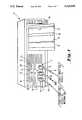
- FIG. 1depicts a perspective view of a fetal monitor.
- FIG. 2is a block diagram of an apparatus for performing coincidence detection in accordance with the present invention.
- FIG. 3is a flowchart outlining the operation of the apparatus of FIG. 2.
- FIG. 4depicts timing diagrams of two heart rate traces, an intermediate sign counting variable and the coincidence indicator of the apparatus of FIG. 2.
- FIG. 5depicts a print-out of a fetal monitor illustrating coincidence detection.
- FIG. 6is a block diagram of a second apparatus for performing coincidence detection in accordance with the present invention.
- FIG. 7is a flowchart outlining the operation of the apparatus of FIG. 6.
- FIG. 8depicts a third apparatus for performing coincidence detection in accordance with the present invention.
- FIG. 9is a flowchart outlining the operation of the apparatus of FIG. 8.
- FIG. 10is a block diagram of an adaptive filter.
- FIG. 1depicts a fetal monitor used to monitor the heart rate of a fetus during pregnancy and labor, and to record uterus (or labor) activity. Simultaneous assessment of the fetal heart rate and uterus activity allows a precise determination of the fetal condition.
- Fetal monitor 1comprises three jacks 2, 3, 4 for the insertion of appropriate connectors 5, 6, 7. These connectors are linked via cables 8, 9, 10 to corresponding transducers (not shown here). Jack 3 is an inlet for the toco (uterus activity) transducer. Although this is an important parameter for the assessment of the fetal condition, it is not a subject of the present invention and is therefore not discussed in detail herein.
- the signal measured via the toco channelis recorded on a thermal printer which is built into the monitor 1. Paper 11 is used by the thermal printer to record the parameter traces.
- the toco recordingis denoted as 12. Further, the measured toco value is optically indicated by means of display 13, a combination of 7-segment displays.
- Jack 4is an inlet for the fetal heart activity signal.
- Two different connectors 7may be used.
- a fetal scalp electrodeAfter rupture of the membrane (during second-stage labor and birth) a fetal scalp electrode, which is applied intravaginally, may be used. Although this method (called “direct ECG”) yields excellent results, it cannot be used in pre-birth applications and during pregnancy.
- another transducernamely an ultrasound (US) transducer.
- the ultrasound transduceremits bursts of high-frequency ultrasound waves and receives the ultrasound signals reflected by the maternal or fetal tissue and bones. The frequency of the reflected ultrasound waves is shifted with respect to their original frequency due to the Doppler effect.
- a demodulator with subsequent filtersis used to obtain the Doppler signal.
- Peaks in the Doppler signalare indicative of a fetal heart beat; however, since the Doppler signal is usually quite noisy, additional measures must be taken to facilitate detection of a peak.
- the fetal monitor depicted in FIG. 1uses an autocorrelation mechanism therefor.
- the fetal heart rateis calculated as the inverse of the time interval between two successive heart beats. This is an important feature of the fetal monitor since the beat-to-beat heart rate provides valuable diagnostic information.
- the detected fetal heart rateis displayed by means of a 7-segment display 14 and recorded on the thermal printer as heart rate trace 15.
- Backlighting modules 16, 17 and 18indicate the quality of the signal used for fetal heart rate detection.
- Module 16is a red module, module 17 a yellow module and module 18 a green module. As long as the received signal is of good quality, green module 18 is on. When the signal is of worse quality, i.e. heartbeat detection becomes questionable, yellow module 17 is switched on, and green module 18 is switched off. When no fetal beat-to-beat heart rate trace can be recorded, red module 16 indicates poor signal quality.
- Jack 7may also provide a maternal electrocardiogram signal obtained, e.g., by ECG electrodes, a plethysmographic transducer or the like. If this signal is provided, the maternal heart rate trace is also recorded as trace 19. The maternal heart rate may be calculated from beat to beat, but it may also be calculated over longer time intervals.
- Fetal monitor 1further provides a third jack 2 for the insertion of a corresponding connector 5.
- the latteris connected via cable 8 with a second fetal transducer, namely a second fetal scalp electrode or a second ultrasound Doppler transducer.
- These transducersare used in the case of twins to obtain a fetal beat-to-beat heart rate trace of the second fetus. If a second fetal transducer is connected, the beat-to-beat heart rate of the second fetus is recorded as trace 19 instead of the maternal heart rate trace.
- a display 20indicates the value of the second fetal heart rate and backlighting modules 21, 22 and 23 indicate the quality of the second fetal signal.
- the fetal monitoris not limited to recording only two heart rate traces on the internal printer, but may also record three or more heart rate traces, e.g., if signals indicative of the heart beats of a first fetus, a second fetus and the mother are fed to the monitor.
- Other components of fetal monitor 1, such as the power-on button 24,are well known and therefore are not discussed herein.
- the fetal monitor 1is able to compare two heart rate traces and provide a warning whenever coincidence between the heart rate traces is detected.
- This important clinical informationindicates that, e.g., two transducers are inadvertently focused on the same fetal heart or a fetal transducer is detecting signals originating from the maternal placenta or the maternal abdominal aorta.
- coincidence between the corresponding heart rate tracesis an indication that both transducers are recording the maternal heart rate and that the fetal heart is not being monitored; thus a dangerous condition, such as insufficient oxygen supply to the fetus, would not be detected.
- Another situation where the maternal heart trace is recorded instead of fetal heart traceis when the ultrasound Doppler signal contains a Weak component due to the fetal heart and strong components due to the mother. In such cases an autocorrelation algorithm will take the maternal heart rate. Even if the fetal signal becomes stronger, the autocorrelation algorithm tends to stay locked on the maternal signal.
- Fetal monitor 1is able to detect coincidence between the fetal and the maternal heart rate signals. Further, if a second fetal transducer is connected, coincidence checks are made between the second fetal heart rate trace and the maternal heart rate trace, and also between the first fetal heart rate trace and the second fetal heart rate trace. The appropriate backlighting modules are switched to red whenever coincidence is detected. In addition, a warning item is printed on the recorder (as explained below with reference to FIG. 5). Furthermore, a warning signal is fed to a system connector (not shown in FIG. 1) so that a central station connected to the fetal monitor may record it. An acoustic alarm or the like may also be generated.
- FIG. 2is a block diagram of a first embodiment of an apparatus for providing coincidence detection.
- Two heart rate signals HR1 and HR2are fed to a summing circuit 25.
- HR1is fed to a positive input terminal and HR2 to a negative input terminal of summing circuit 25; thus the summing circuit generates a difference signal on line 26.
- Heart rate signals HR1 and HR2may be any combination of the heart rate traces of a first fetus, a second fetus and the mother.
- the difference signal 26is fed to a signum generator 27.
- the signum generatordetermines the sign of the difference signal according to the following equation: ##EQU1## wherein d is the difference signal at the input of the signum generator and s is the signum signal on line 28, i.e., the output of the signum generator.
- signum generator 27is designed to count sign changes, i.e., crossings of the two heart rates. It is understood that the operation of the signum generator could also be defined in a different manner, e.g., as ##EQU2## wherein n is the index number of the samples.
- a further possibilityis to count a difference of zero as a sign change (provided the previous difference has not also been zero) and to determine whether the difference signal continues to move in the same direction (in which case no further sign change is recorded). It is also possible to count every difference of zero as a sign change. This is particularly useful if the two heart rate signals contain little or no jitter.
- the signum signal on line 28is fed to an integrator 29.
- the integratorserves two different functions: first, it integrates (sums) the sign changes; second, it ensures that the integral or the sum of the sign changes does not increase without limitation (i.e., its output decreases slightly if no further sign changes occur). There are two basic ways to implement the second function. The first is to calculate the integral from a finite lower limit which moves with the current point in time to an upper limit which equals the current point in time.
- comparator 31The output of integrator 29 is fed via line 30 to a comparator 31.
- the function of the comparatoris to compare the output of integrator 29 with a predefined or adaptive limit and to generate a warning signal at its output line 32 if the integrated signal exceeds a certain limit, i.e., if sign changes of a significant frequency have been observed.
- comparator 31provides a hysteresis function which is explained in more detail below with reference to FIG. 3.
- the warning signal on line 32may be fed to any appropriate warning means, e.g., means for providing an optical or acoustic alarm, means for providing an annotation on a printer or recorder, or means for adjusting the ultrasound beam when an adjustable ultrasound Doppler transducer is used, e.g., when a transducer with controllable depth selection is used.
- warning meanse.g., means for providing an optical or acoustic alarm, means for providing an annotation on a printer or recorder, or means for adjusting the ultrasound beam when an adjustable ultrasound Doppler transducer is used, e.g., when a transducer with controllable depth selection is used.
- a special property of the heart rate tracesis used for the detection of coincidence between two heart rates, namely that the traces contain a high-frequency component, or "jitter.”
- This jitteris due to both physiological causes and the signal processing algorithm used in the fetal monitor.
- the extent of the Doppler signal representing the movement of the fetal heart walls and heart valvesis quite long, so that its start and end points cannot be determined precisely in time. This leads to inaccurate beat-to-beat heart rates, and therefore to a jitter signal superimposed on the heart rate trace.
- the heart rateis high, and the sampling frequency is in the range of 200 Hz or less, the QRS complexes in the direct electrocardiogram cannot be precisely defined in time, thus causing jitter.
- the present inventionmakes use of the jitter in the heart rate trace.
- heart rate traces originating from the same personcomprise a significant number of crossings, i.e., sign changes, of the difference signal; therefore, the frequency of sign changes of the difference signal is an indication of coincidence.
- the jitteris not sufficient to trigger the signum generator sufficiently frequently, e.g., in the case of a silent heart rate trace or if one heart rate has a constant offset, an artificial jitter signal can be superimposed on one or both of the heart rate traces. Further optimization can be obtained by additional filters, delay elements for the compensation of different processing times and variation of tolerance windows.
- FIG. 3which explains how the individual components of FIG. 2 operate or, if a microprocessor-based system is used, describes the operation of a subroutine executed periodically.
- Heart rate traces HR1 and HR2are obtained from a fetus and the mother. If twins are monitored, these could also be heart rate traces from a first fetus and a second fetus, or from a second fetus and the mother. If signals from two fetuses and a mother are processed, the subroutine in FIG. 3 is executed for all possible combinations of these signals, i.e., fetus 1/mother, fetus 1/fetus 2 and fetus 2/mother.
- the fetal heart rate tracesare beat-to-beat heart rates; the maternal heart rate may be a beat-to-beat heart rate or a heart rate calculated on the basis of a longer time constant.
- step 34The signum function calculated in step 34 is then compared with the sign of the previous difference (step 35). If the signs are equal, operation proceeds to step 36. If not, a variable SIG -- COUNT is increased by a constant C1 (step 37).
- step 36the variable SIG -- COUNT, which is indicative of the frequency of the sign changes, is reduced in accordance with a predetermined factor C2.
- a predetermined factor C2an exponential average of SIG -- COUNT is taken, although a moving average can be used as well.
- SIG -- COUNTThe calculated value of SIG -- COUNT is then compared with a first limit L1 (step 38). If SIG -- COUNT exceeds this limit, a coincidence indicator COIN(n), which operates as a warning signal, is set to 1 (step 39) and operation stops (step 40).
- step 41If SIG -- COUNT has not exceeded limit L1, it is further checked against a second, lower limit L1-C3 (step 41). If the second limit is exceeded, i.e., the value of SIG -- COUNT is between the upper and the lower limits, a further check is made to see whether the warning signal COIN(n-1) is set (step 42). If so, the warning signal is kept in its "true” state in order to avoid jitter of the warning signal caused by a minimal decrease of SIG -- COUNT, i.e, COIN(n) is set to 1 (step 39). Note that steps 41 and 42 implement the hysteresis function mentioned above.
- variable SIG -- COUNTdoes not exceed either of the limits, or if only the lower limit is exceeded without a warning signal having been generated during the previous cycle, coincidence warning signal COIN(n) is set to zero (step 43), and execution stops.
- the operation of the coincidence detector described in FIGS. 2 and 3will now be explained with reference to the exemplary traces depicted in FIG. 4.
- the upper diagramdepicts two beat-to-beat heart rate traces originating from two fetuses.
- the horizontal axisdenotes the time.
- the next diagramdepicts the trace 45 of variable SIG -- COUNT.
- the upper limit L1has been set to 6 and the lower limit L1-C3 has been set to 4.
- the values of SIG -- COUNTare real numbers in the example, however integers are preferable if a microcomputer is used.
- the diagram at the bottom of FIG. 4depicts the trace 48 of the coincidence warning signal COIN over time.
- a first time periodt 0 ⁇ t ⁇ t 1
- SIG -- COUNTis increasing, it has not yet reached the limit L1 and therefore no warning signal is generated.
- the value of the SIG -- COUNTreturns to the lower limit and then exceeds the upper limit again, the warning signal remains on. This is caused by the hysteresis function provided by the comparator, which prevents the warning signal from being switched on and off too frequently.
- FIG. 5depicts an exemplary printout on the thermal printer of a fetal monitor. Whenever a significant number of crossings of the two heart rate traces 48, 49 has been detected, a question mark is printed (references numbers 50a, 50b, 50c) to indicate possible coincidence.
- FIG. 6Another embodiment of the present invention is shown in FIG. 6.
- the two heart rate traces HR1 and HR2are fed to a summing circuit 51 which calculates the difference between the two heart rate traces.
- the signal on line 52is fed to an absolute value generator 53, which simply converts a negative sign of the difference into a positive sign.
- the signalis then fed via line 54 to an integrator 55 and then via line 56 to a comparison circuit 57, thus generating an output signal on line 58.
- Integrator 55 and comparison circuit 57are similar to elements 29 and 31 in FIG. 2.
- the major difference between the circuits depicted in FIGS. 2 and 6is that, in the environment of FIG. 6, an absolute value generator is used instead of a signum generator.
- the circuit of FIG. 6actually calculates the area between the two heart rate traces.
- the heart rate traces fed to the circuit of FIG. 6are pre-filtered, or averaged, to avoid errors caused by jitter.
- this flowchartrepresents a subroutine which is executed on a periodic basis.
- Step 59Operation starts at label "START," reference numeral 59.
- Variable h(n)is then calculated as the absolute value of the difference between heart rate traces HR1 and HR2 (step 60).
- Operationthen proceeds to step 61, in which a sliding average is calculated over c samples (see equation (4)).
- Step 62depicts an alternative embodiment wherein an exponential average is calculated, i.e., step 61 could be replaced by step 62.
- Steps 63, 64 and 65implement a hysteresis function. Reference is made to the corresponding steps 38, 41 and 42 of FIG. 3. Depending on the result of these comparisons, the coincidence warning signal is either set to 0 (step 66) or 1 (step 67). Operation stops at step 68.
- FIGS. 8 and 9A further embodiment of the invention is depicted in FIGS. 8 and 9.
- the two heart rate traces HR1, HR2are fed to a cross-correlator 69.
- the amplitude of the output of the cross-correlator on line 70is fed to a comparison circuit 71, which generates an output on line 72.
- the output of the cross-correlatorprovides an indication of the correlation between the two heart rate signals. That is, the higher the amplitude of the cross-correlation signal, the higher the correlation (or coincidence) between the two heart rate signals.
- FIG. 8depicts only a typical example of how cross-correlation may be used to detect coincidence between the heart rate signals.
- Other embodimentsmay be used as well; e.g., the raw (unprocessed) signals received from ultrasound transducers or ECG probes could be directly fed to a cross-correlation circuit, without heart rate generation or other pre-processing.
- this solutionsaves processing time, it requires a considerably higher sampling frequency and therefore a faster cross-correlator.
- FIG. 9This flowchart represents operation of corresponding analog or digital circuitry, or the operation of a microprocessor. In the latter case, the microprocessor executes the associated subroutine on a periodic basis.
- a cross-correlationis performed between the two time-dependent heart rate traces HR1(t) and HR2(t) in accordance with the equation shown at step 74. It should be noted that this equation represents the operation of an ideal cross-correlator. Actual cross-correlators do not take the integral from negative to positive infinity; they use the sum instead of the integral and the summing limits are finite values.
- the result of the cross-correlationis a function X(t) the amplitude of which is indicative of the correlation or coincidence between the two incoming signals.
- the correlation signal X(t)is then compared with upper and lower limits (L1 and L1-C1) to implement a hysteresis function (steps 75 to 77).
- the coincidence warning signalis then either set to 0 (step 78) or 1 (step 79). Operation stops at step 80.
- FIG. 10depicts a block diagram of an adaptive filter used for coincidence detection.
- the digitized samples of a first ultrasound signal X(n)are fed to the filter with a multiplicity of delay circuits 81, 82 and 83 (the dotted line between elements 82 and 83 indicates that there might be further delay circuits).
- the signalis fed, via amplifiers 84 to 87 with adjustable (adaptive) gain, to a summing point 88.
- the difference between the sum of all these signals and the second heart rate trace Y(n)is calculated at element 89, thus generating a signal e(n).
- the weighting factors (or gain) h 0 , h 1 , h 2 . . . h n-1 of the variable amplifiersare controlled in accordance with e(n).
- the output s(n) of the digital filteris given by ##EQU5## with x(n) being the first ultrasound signal and h 0 . . . h n-1 being the variable filter coefficients.
- x(n)being the first ultrasound signal
- h 0 . . . h n-1being the variable filter coefficients.
- the filter coefficientscan be calculated by the following recursion formula:
- kis a constant selected on the basis of the particular application.
- the filter coefficientsare periodically optimized so that the output of the filter approaches the second ultrasound signal; i.e., so that the difference signal e(n) is minimized. If the two ultrasound signals are approximately equal, the filter coefficients become stable and may be used to determine the phase between the two ultrasound signals. If the ultrasound signals are equal, the phase is constant. Therefore the filter coefficients can be used to determine whether the two ultrasound signals are coincident. The final determination can be made in a comparison circuit as described in the previous examples.
- the adaptive filter methodyields the best results when the two ultrasound signals comprise little jitter.
- the embodiment depicted in FIG. 10is particularly useful if raw (unprocessed) ultrasound signals are evaluated; however the heart rate traces could be processed in the same or a similar manner.
- Another embodiment of the inventionuses the difference or the absolute value of the difference between the two heart rate traces to determine coincidence.
- This differencemay be compared with the predefined or adaptive limit and may also comprise a hysteresis function. This method is particularly useful when direct electrocardiograms are processed.
- Ultrasound transducers with adjustable, or adaptive, characteristicsare already available on the market.
- the ultrasound transducermay be able to search, on an automatic basis, for the correct depth where the fetal heart can be found.
- a transducer of this kindis described in European patent application EP-A-204 192. If such an automatic ultrasound transducer is used, the warning signal may advantageously be used to start a new search cycle, i.e., to search for another physiological object.
Landscapes
- Health & Medical Sciences (AREA)
- Life Sciences & Earth Sciences (AREA)
- Molecular Biology (AREA)
- Heart & Thoracic Surgery (AREA)
- Biophysics (AREA)
- Veterinary Medicine (AREA)
- Pathology (AREA)
- Public Health (AREA)
- Engineering & Computer Science (AREA)
- Animal Behavior & Ethology (AREA)
- Surgery (AREA)
- Medical Informatics (AREA)
- Physics & Mathematics (AREA)
- Cardiology (AREA)
- Biomedical Technology (AREA)
- General Health & Medical Sciences (AREA)
- Gynecology & Obstetrics (AREA)
- Pregnancy & Childbirth (AREA)
- Radiology & Medical Imaging (AREA)
- Nuclear Medicine, Radiotherapy & Molecular Imaging (AREA)
- Physiology (AREA)
- Pediatric Medicine (AREA)
- Reproductive Health (AREA)
- Ultra Sonic Daignosis Equipment (AREA)
- Measuring Pulse, Heart Rate, Blood Pressure Or Blood Flow (AREA)
Abstract
Description
e(n)=s(n)-y(n) (7)
h.sub.i (n+1)=h.sub.i (n)+2k*e(n)*x(n-i) (8)
Claims (47)
Priority Applications (1)
| Application Number | Priority Date | Filing Date | Title |
|---|---|---|---|
| US07/676,853US5123420A (en) | 1991-03-25 | 1991-03-25 | Method and apparatus for processing heart rate traces in a fetal monitor |
Applications Claiming Priority (1)
| Application Number | Priority Date | Filing Date | Title |
|---|---|---|---|
| US07/676,853US5123420A (en) | 1991-03-25 | 1991-03-25 | Method and apparatus for processing heart rate traces in a fetal monitor |
Publications (1)
| Publication Number | Publication Date |
|---|---|
| US5123420Atrue US5123420A (en) | 1992-06-23 |
Family
ID=24716292
Family Applications (1)
| Application Number | Title | Priority Date | Filing Date |
|---|---|---|---|
| US07/676,853Expired - LifetimeUS5123420A (en) | 1991-03-25 | 1991-03-25 | Method and apparatus for processing heart rate traces in a fetal monitor |
Country Status (1)
| Country | Link |
|---|---|
| US (1) | US5123420A (en) |
Cited By (62)
| Publication number | Priority date | Publication date | Assignee | Title |
|---|---|---|---|---|
| US5265616A (en)* | 1991-11-13 | 1993-11-30 | Fukuda Denshi Kabushiki Kaisha | Biological information processing and automatically displaying apparatus |
| US5442940A (en)* | 1991-10-24 | 1995-08-22 | Hewlett-Packard Company | Apparatus and method for evaluating the fetal condition |
| US5529073A (en)* | 1992-05-21 | 1996-06-25 | Hewlett-Packard Company | Method and apparatus for recording physiologic signals |
| DE19524092A1 (en)* | 1995-07-01 | 1997-01-02 | Hewlett Packard Gmbh | Data compression applied to cardiograph signals |
| US5666959A (en)* | 1995-08-30 | 1997-09-16 | British Technology Group Limited | Fetal heart rate monitoring |
| US5810740A (en)* | 1995-11-13 | 1998-09-22 | Heart Rhythm Technologies, Inc. | System and method for analyzing electrogram waveforms |
| US5817035A (en)* | 1994-11-24 | 1998-10-06 | The Institute Of Respiratory Medicine Ltd. | Biophysical foetal monitor |
| USD407159S (en) | 1998-04-30 | 1999-03-23 | Anne-Marie Roberg | Pre-natal heartbeat monitor |
| EP0904727A1 (en) | 1998-06-05 | 1999-03-31 | Hewlett-Packard Company | Pulse rate and heart rate coincidence detection for pulse oximetry |
| US6024701A (en)* | 1998-08-27 | 2000-02-15 | T.A.O. Medical Technologies Ltd. | Method of and system for estimating placenta and fetus well being using system identification techniques |
| US6115624A (en)* | 1997-07-30 | 2000-09-05 | Genesis Technologies, Inc. | Multiparameter fetal monitoring device |
| US6340346B1 (en) | 1999-11-26 | 2002-01-22 | T.A.O. Medical Technologies Ltd. | Method and system for system identification of physiological systems |
| US20030158466A1 (en)* | 1997-01-27 | 2003-08-21 | Lynn Lawrence A. | Microprocessor system for the analysis of physiologic and financial datasets |
| US6662043B1 (en)* | 2000-08-03 | 2003-12-09 | Ge Marquette Medical Systems, Inc. | Heart beat coincidence detection |
| US6751498B1 (en) | 1999-03-15 | 2004-06-15 | The Johns Hopkins University | Apparatus and method for non-invasive, passive fetal heart monitoring |
| US20040230126A1 (en)* | 2002-12-05 | 2004-11-18 | Welch Allyn, Inc. | ECG monitoring apparatus with incorporated printer |
| US20050113708A1 (en)* | 2003-07-18 | 2005-05-26 | Roland Priemer | Extraction of heart sound of fetus from heart sound information that comprises plurality of mixtures of plurality of heart sounds of plurality of fetuses |
| US20050203352A1 (en)* | 2004-03-08 | 2005-09-15 | Ammar Al-Ali | Physiological parameter system |
| US20050277841A1 (en)* | 2004-06-10 | 2005-12-15 | Adnan Shennib | Disposable fetal monitor patch |
| US20060030782A1 (en)* | 2004-08-05 | 2006-02-09 | Adnan Shennib | Heart disease detection patch |
| US20060030781A1 (en)* | 2004-08-05 | 2006-02-09 | Adnan Shennib | Emergency heart sensor patch |
| US20060155206A1 (en)* | 1997-01-27 | 2006-07-13 | Lynn Lawrence A | System and method for sound and oximetry integration |
| US20060155207A1 (en)* | 1997-01-27 | 2006-07-13 | Lynn Lawrence A | System and method for detection of incomplete reciprocation |
| US20060264767A1 (en)* | 2005-05-17 | 2006-11-23 | Cardiovu, Inc. | Programmable ECG sensor patch |
| US20060270938A1 (en)* | 2005-05-31 | 2006-11-30 | Ge Medical Systems Global Technology Company, Llc | Ultrasound diagnostic apparatus and ultrasound diagnostic method |
| US20070027396A1 (en)* | 2005-07-26 | 2007-02-01 | American University of Sharajah | Separating mixed signals |
| US20070129639A1 (en)* | 2004-01-11 | 2007-06-07 | Hongxuan Zhang | Methods and analysis for cardiac ischemia detection |
| US20070191728A1 (en)* | 2006-02-10 | 2007-08-16 | Adnan Shennib | Intrapartum monitor patch |
| US20070255184A1 (en)* | 2006-02-10 | 2007-11-01 | Adnan Shennib | Disposable labor detection patch |
| US20070270701A1 (en)* | 2006-05-02 | 2007-11-22 | Orenstein Nicholas P | Configuration for phonography cardio heart monitoring |
| US20070276251A1 (en)* | 2006-05-02 | 2007-11-29 | Orenstein Nicholas P | Transducers with acoustic impedance matching for passive cardio monitoring |
| WO2009013701A3 (en)* | 2007-07-24 | 2009-06-25 | Philips Intellectual Property | Method of monitoring a fetal heart rate |
| US7593765B2 (en) | 2006-05-02 | 2009-09-22 | Lono Medical Systems, Llc | Fetal heart monitoring |
| US20090240126A1 (en)* | 2008-03-24 | 2009-09-24 | Nellcor Puritan Bennett Llc | Method And System For Classification of Photo-Plethysmographically Detected Respiratory Effort |
| US20090247837A1 (en)* | 2008-03-27 | 2009-10-01 | Nellcor Puritan Bennett Llc | System And Method For Diagnosing Sleep Apnea |
| GB2458791A (en)* | 2008-03-29 | 2009-10-07 | K2 Medical Systems Ltd | Signal Analyser for Use in Displaying Information Related to Physiological Parameters |
| US20100022903A1 (en)* | 2008-07-28 | 2010-01-28 | Sitzman David A | System and method for signal quality indication and false alarm reduction in ecg monitoring systems |
| US20100063366A1 (en)* | 2008-09-10 | 2010-03-11 | James Ochs | System And Method For Detecting Ventilatory Instability |
| US20100168528A1 (en)* | 2008-12-29 | 2010-07-01 | Mark Evans | Identifying the level of fetal risk during labor |
| US20100191117A1 (en)* | 2009-01-29 | 2010-07-29 | The General Electric Company | Method and Device for Controlling Transmission Power of an Active Transducer |
| US20100191118A1 (en)* | 2009-01-29 | 2010-07-29 | The General Electric Company | System and Method for Measuring the Instantaneous Period of a Quasi-Periodic Signal |
| US7818050B2 (en) | 2006-05-02 | 2010-10-19 | Lono Medical Systems, Llc | Passive phonography heart monitor |
| CN102499640A (en)* | 2011-10-26 | 2012-06-20 | 深圳市理邦精密仪器股份有限公司 | Generation method and system of digital fetal monitoring bar chart |
| US8275553B2 (en) | 2008-02-19 | 2012-09-25 | Nellcor Puritan Bennett Llc | System and method for evaluating physiological parameter data |
| US8666467B2 (en) | 2001-05-17 | 2014-03-04 | Lawrence A. Lynn | System and method for SPO2 instability detection and quantification |
| US8666481B2 (en) | 2009-02-27 | 2014-03-04 | Analogic Corporation | Fetal movement monitor |
| US8728001B2 (en) | 2006-02-10 | 2014-05-20 | Lawrence A. Lynn | Nasal capnographic pressure monitoring system |
| WO2015005796A1 (en)* | 2013-07-12 | 2015-01-15 | Laerdal Global Health As | Fetal heart rate monitoring assembly |
| US9031793B2 (en) | 2001-05-17 | 2015-05-12 | Lawrence A. Lynn | Centralized hospital monitoring system for automatically detecting upper airway instability and for preventing and aborting adverse drug reactions |
| US9042952B2 (en) | 1997-01-27 | 2015-05-26 | Lawrence A. Lynn | System and method for automatic detection of a plurality of SPO2 time series pattern types |
| US9053222B2 (en) | 2002-05-17 | 2015-06-09 | Lawrence A. Lynn | Patient safety processor |
| CN105138823A (en)* | 2015-07-28 | 2015-12-09 | 中国科学院电子学研究所 | Method for detecting quality of physiological signal based on self-correlation function |
| US9468378B2 (en) | 1997-01-27 | 2016-10-18 | Lawrence A. Lynn | Airway instability detection system and method |
| US20160367214A1 (en)* | 2015-06-17 | 2016-12-22 | Laerdal Medical As | Fetal heart rate monitoring assembly |
| WO2017046070A1 (en)* | 2015-09-15 | 2017-03-23 | Koninklijke Philips N.V. | Device and method for determining fetal heart rate |
| US20180055382A1 (en)* | 2016-08-23 | 2018-03-01 | Covidien Lp | Automatic estimation of pulse deficit |
| US11224375B2 (en) | 2017-02-28 | 2022-01-18 | Mayo Foundation For Medical Education And Research | Systems and methods for fetal monitoring |
| US11266375B2 (en) | 2015-09-15 | 2022-03-08 | Koninklijke Philips N.V. | Device and method for determining fetal heart rate |
| US11559276B2 (en) | 2018-05-02 | 2023-01-24 | Koninklijke Philips N.V. | Systems and methods for ultrasound screening |
| CN116211345A (en)* | 2021-12-03 | 2023-06-06 | 深圳市理邦精密仪器股份有限公司 | Integrated fetal heart rate Doppler |
| US11786169B2 (en) | 2016-11-21 | 2023-10-17 | Mark Evans | System, apparatus, and method for monitoring and assessing the level of fetal risk during labor |
| US12315639B2 (en) | 2019-08-01 | 2025-05-27 | Mark Evans | Methods and apparatus for reducing the risk, and identifying the existence, of neurological injury to a human fetus during and before labor |
Citations (9)
| Publication number | Priority date | Publication date | Assignee | Title |
|---|---|---|---|---|
| US3827428A (en)* | 1971-01-20 | 1974-08-06 | R Hon | Bipolar electrode structure for monitoring fetal heartbeat and the like |
| US4038536A (en)* | 1976-03-29 | 1977-07-26 | Rockwell International Corporation | Adaptive recursive least mean square error filter |
| US4519396A (en)* | 1979-03-30 | 1985-05-28 | American Home Products Corporation (Del.) | Fetal heart rate monitor apparatus and method for combining electrically and mechanically derived cardiographic signals |
| US4537200A (en)* | 1983-07-07 | 1985-08-27 | The Board Of Trustees Of The Leland Stanford Junior University | ECG enhancement by adaptive cancellation of electrosurgical interference |
| US4569356A (en)* | 1984-11-05 | 1986-02-11 | Nihon Kohden Corporation | Method and apparatus for detecting fetal heart rate by autocorrelation |
| US4751931A (en)* | 1986-09-22 | 1988-06-21 | Allegheny-Singer Research Institute | Method and apparatus for determining his-purkinje activity |
| US4781200A (en)* | 1985-10-04 | 1988-11-01 | Baker Donald A | Ambulatory non-invasive automatic fetal monitoring system |
| US4793361A (en)* | 1987-03-13 | 1988-12-27 | Cardiac Pacemakers, Inc. | Dual channel P-wave detection in surface electrocardiographs |
| US4898179A (en)* | 1985-06-17 | 1990-02-06 | Vladimir Sirota | Device for detecting, monitoring, displaying and recording of material and fetal vital signs and permitting communication between a woman and her fetus |
- 1991
- 1991-03-25USUS07/676,853patent/US5123420A/ennot_activeExpired - Lifetime
Patent Citations (9)
| Publication number | Priority date | Publication date | Assignee | Title |
|---|---|---|---|---|
| US3827428A (en)* | 1971-01-20 | 1974-08-06 | R Hon | Bipolar electrode structure for monitoring fetal heartbeat and the like |
| US4038536A (en)* | 1976-03-29 | 1977-07-26 | Rockwell International Corporation | Adaptive recursive least mean square error filter |
| US4519396A (en)* | 1979-03-30 | 1985-05-28 | American Home Products Corporation (Del.) | Fetal heart rate monitor apparatus and method for combining electrically and mechanically derived cardiographic signals |
| US4537200A (en)* | 1983-07-07 | 1985-08-27 | The Board Of Trustees Of The Leland Stanford Junior University | ECG enhancement by adaptive cancellation of electrosurgical interference |
| US4569356A (en)* | 1984-11-05 | 1986-02-11 | Nihon Kohden Corporation | Method and apparatus for detecting fetal heart rate by autocorrelation |
| US4898179A (en)* | 1985-06-17 | 1990-02-06 | Vladimir Sirota | Device for detecting, monitoring, displaying and recording of material and fetal vital signs and permitting communication between a woman and her fetus |
| US4781200A (en)* | 1985-10-04 | 1988-11-01 | Baker Donald A | Ambulatory non-invasive automatic fetal monitoring system |
| US4751931A (en)* | 1986-09-22 | 1988-06-21 | Allegheny-Singer Research Institute | Method and apparatus for determining his-purkinje activity |
| US4793361A (en)* | 1987-03-13 | 1988-12-27 | Cardiac Pacemakers, Inc. | Dual channel P-wave detection in surface electrocardiographs |
Cited By (103)
| Publication number | Priority date | Publication date | Assignee | Title |
|---|---|---|---|---|
| US5442940A (en)* | 1991-10-24 | 1995-08-22 | Hewlett-Packard Company | Apparatus and method for evaluating the fetal condition |
| US5265616A (en)* | 1991-11-13 | 1993-11-30 | Fukuda Denshi Kabushiki Kaisha | Biological information processing and automatically displaying apparatus |
| US5529073A (en)* | 1992-05-21 | 1996-06-25 | Hewlett-Packard Company | Method and apparatus for recording physiologic signals |
| US20070149860A1 (en)* | 1992-08-19 | 2007-06-28 | Lynn Lawrence A | Microprocessor system for the analysis of physiologic and financial datasets |
| US8152732B2 (en) | 1992-08-19 | 2012-04-10 | Lynn Lawrence A | Microprocessor system for the analysis of physiologic and financial datasets |
| US5817035A (en)* | 1994-11-24 | 1998-10-06 | The Institute Of Respiratory Medicine Ltd. | Biophysical foetal monitor |
| DE19524092A1 (en)* | 1995-07-01 | 1997-01-02 | Hewlett Packard Gmbh | Data compression applied to cardiograph signals |
| US5724032A (en)* | 1995-07-01 | 1998-03-03 | Hewlett-Packard Company | Method and apparatus for compressing and displaying digital data, particularly the heart rate of fetal monitors |
| US5666959A (en)* | 1995-08-30 | 1997-09-16 | British Technology Group Limited | Fetal heart rate monitoring |
| US5810740A (en)* | 1995-11-13 | 1998-09-22 | Heart Rhythm Technologies, Inc. | System and method for analyzing electrogram waveforms |
| US8187201B2 (en) | 1997-01-27 | 2012-05-29 | Lynn Lawrence A | System and method for applying continuous positive airway pressure |
| US7758503B2 (en) | 1997-01-27 | 2010-07-20 | Lynn Lawrence A | Microprocessor system for the analysis of physiologic and financial datasets |
| US8241213B2 (en) | 1997-01-27 | 2012-08-14 | Lynn Lawrence A | Microprocessor system for the analysis of physiologic datasets |
| US20030158466A1 (en)* | 1997-01-27 | 2003-08-21 | Lynn Lawrence A. | Microprocessor system for the analysis of physiologic and financial datasets |
| US9042952B2 (en) | 1997-01-27 | 2015-05-26 | Lawrence A. Lynn | System and method for automatic detection of a plurality of SPO2 time series pattern types |
| US9468378B2 (en) | 1997-01-27 | 2016-10-18 | Lawrence A. Lynn | Airway instability detection system and method |
| US20060155206A1 (en)* | 1997-01-27 | 2006-07-13 | Lynn Lawrence A | System and method for sound and oximetry integration |
| US20060276695A9 (en)* | 1997-01-27 | 2006-12-07 | Lynn Lawrence A | Microprocessor system for the analysis of physiologic and financial datasets |
| US20060155207A1 (en)* | 1997-01-27 | 2006-07-13 | Lynn Lawrence A | System and method for detection of incomplete reciprocation |
| US6115624A (en)* | 1997-07-30 | 2000-09-05 | Genesis Technologies, Inc. | Multiparameter fetal monitoring device |
| USD407159S (en) | 1998-04-30 | 1999-03-23 | Anne-Marie Roberg | Pre-natal heartbeat monitor |
| US6178343B1 (en) | 1998-06-05 | 2001-01-23 | Hewlett Packard Company | Pulse rate and heart rate coincidence detection for pulse oximetry |
| EP0904727A1 (en) | 1998-06-05 | 1999-03-31 | Hewlett-Packard Company | Pulse rate and heart rate coincidence detection for pulse oximetry |
| US6024701A (en)* | 1998-08-27 | 2000-02-15 | T.A.O. Medical Technologies Ltd. | Method of and system for estimating placenta and fetus well being using system identification techniques |
| US6751498B1 (en) | 1999-03-15 | 2004-06-15 | The Johns Hopkins University | Apparatus and method for non-invasive, passive fetal heart monitoring |
| US6340346B1 (en) | 1999-11-26 | 2002-01-22 | T.A.O. Medical Technologies Ltd. | Method and system for system identification of physiological systems |
| US10058269B2 (en) | 2000-07-28 | 2018-08-28 | Lawrence A. Lynn | Monitoring system for identifying an end-exhalation carbon dioxide value of enhanced clinical utility |
| US8932227B2 (en) | 2000-07-28 | 2015-01-13 | Lawrence A. Lynn | System and method for CO2 and oximetry integration |
| DE10137891B4 (en)* | 2000-08-03 | 2014-07-10 | Ge Marquette Medical Systems, Inc. | Heartbeat coincidence detection |
| US6662043B1 (en)* | 2000-08-03 | 2003-12-09 | Ge Marquette Medical Systems, Inc. | Heart beat coincidence detection |
| US9031793B2 (en) | 2001-05-17 | 2015-05-12 | Lawrence A. Lynn | Centralized hospital monitoring system for automatically detecting upper airway instability and for preventing and aborting adverse drug reactions |
| US8666467B2 (en) | 2001-05-17 | 2014-03-04 | Lawrence A. Lynn | System and method for SPO2 instability detection and quantification |
| US8862196B2 (en) | 2001-05-17 | 2014-10-14 | Lawrence A. Lynn | System and method for automatic detection of a plurality of SP02 time series pattern types |
| US11439321B2 (en) | 2001-05-17 | 2022-09-13 | Lawrence A. Lynn | Monitoring system for identifying an end-exhalation carbon dioxide value of enhanced clinical utility |
| US9053222B2 (en) | 2002-05-17 | 2015-06-09 | Lawrence A. Lynn | Patient safety processor |
| US20040230126A1 (en)* | 2002-12-05 | 2004-11-18 | Welch Allyn, Inc. | ECG monitoring apparatus with incorporated printer |
| US20050113708A1 (en)* | 2003-07-18 | 2005-05-26 | Roland Priemer | Extraction of heart sound of fetus from heart sound information that comprises plurality of mixtures of plurality of heart sounds of plurality of fetuses |
| US7435224B2 (en)* | 2003-07-18 | 2008-10-14 | The Board Of Trustees Of The University Of Illinois | Extraction of heart sound of fetus from heart sound information that comprises plurality of mixtures of plurality of heart sounds of plurality of fetuses |
| US20090036789A1 (en)* | 2003-07-18 | 2009-02-05 | Roland Priemer | Extraction of heart sound of fetus from heart sound information that comprises plurality of mixtures of plurality of heart sounds of plurality of fetuses |
| US20070129639A1 (en)* | 2004-01-11 | 2007-06-07 | Hongxuan Zhang | Methods and analysis for cardiac ischemia detection |
| US7415297B2 (en)* | 2004-03-08 | 2008-08-19 | Masimo Corporation | Physiological parameter system |
| US20080300471A1 (en)* | 2004-03-08 | 2008-12-04 | Masimo Corporation | Physiological parameter system |
| US11937949B2 (en) | 2004-03-08 | 2024-03-26 | Masimo Corporation | Physiological parameter system |
| US8721542B2 (en)* | 2004-03-08 | 2014-05-13 | Masimo Corporation | Physiological parameter system |
| US10098591B2 (en) | 2004-03-08 | 2018-10-16 | Masimo Corporation | Physiological parameter system |
| US20050203352A1 (en)* | 2004-03-08 | 2005-09-15 | Ammar Al-Ali | Physiological parameter system |
| US20050277841A1 (en)* | 2004-06-10 | 2005-12-15 | Adnan Shennib | Disposable fetal monitor patch |
| US20060030781A1 (en)* | 2004-08-05 | 2006-02-09 | Adnan Shennib | Emergency heart sensor patch |
| US20060030782A1 (en)* | 2004-08-05 | 2006-02-09 | Adnan Shennib | Heart disease detection patch |
| US20060264767A1 (en)* | 2005-05-17 | 2006-11-23 | Cardiovu, Inc. | Programmable ECG sensor patch |
| US8688189B2 (en) | 2005-05-17 | 2014-04-01 | Adnan Shennib | Programmable ECG sensor patch |
| US20060270938A1 (en)* | 2005-05-31 | 2006-11-30 | Ge Medical Systems Global Technology Company, Llc | Ultrasound diagnostic apparatus and ultrasound diagnostic method |
| US20070027396A1 (en)* | 2005-07-26 | 2007-02-01 | American University of Sharajah | Separating mixed signals |
| US7474915B2 (en) | 2005-07-26 | 2009-01-06 | American University Of Sharjah And Arab Science And Technology Foundation | Separating mixed signals containing a distorted signal |
| US20070191728A1 (en)* | 2006-02-10 | 2007-08-16 | Adnan Shennib | Intrapartum monitor patch |
| US20070255184A1 (en)* | 2006-02-10 | 2007-11-01 | Adnan Shennib | Disposable labor detection patch |
| US8728001B2 (en) | 2006-02-10 | 2014-05-20 | Lawrence A. Lynn | Nasal capnographic pressure monitoring system |
| US7818050B2 (en) | 2006-05-02 | 2010-10-19 | Lono Medical Systems, Llc | Passive phonography heart monitor |
| US20070270701A1 (en)* | 2006-05-02 | 2007-11-22 | Orenstein Nicholas P | Configuration for phonography cardio heart monitoring |
| US20070276251A1 (en)* | 2006-05-02 | 2007-11-29 | Orenstein Nicholas P | Transducers with acoustic impedance matching for passive cardio monitoring |
| US7539534B2 (en) | 2006-05-02 | 2009-05-26 | Lono Medical Systems, Llc | Configuration for phonography cardio heart monitoring |
| US7593765B2 (en) | 2006-05-02 | 2009-09-22 | Lono Medical Systems, Llc | Fetal heart monitoring |
| WO2009013701A3 (en)* | 2007-07-24 | 2009-06-25 | Philips Intellectual Property | Method of monitoring a fetal heart rate |
| US20100168596A1 (en)* | 2007-07-24 | 2010-07-01 | Koninklijke Philips Electronics N.V. | Method of monitoring a fetal heart rate |
| US9610060B2 (en) | 2007-07-24 | 2017-04-04 | Koninklijke Philips N.V. | Method of monitoring a fetal heart rate |
| US8781753B2 (en) | 2008-02-19 | 2014-07-15 | Covidien Lp | System and method for evaluating physiological parameter data |
| US8275553B2 (en) | 2008-02-19 | 2012-09-25 | Nellcor Puritan Bennett Llc | System and method for evaluating physiological parameter data |
| US10532170B2 (en) | 2008-03-24 | 2020-01-14 | Covidien Lp | Method and system for classification of photo-plethysmographically detected respiratory effort |
| US20090240126A1 (en)* | 2008-03-24 | 2009-09-24 | Nellcor Puritan Bennett Llc | Method And System For Classification of Photo-Plethysmographically Detected Respiratory Effort |
| US8365730B2 (en) | 2008-03-24 | 2013-02-05 | Covidien Lp | Method and system for classification of photo-plethysmographically detected respiratory effort |
| US9044558B2 (en) | 2008-03-24 | 2015-06-02 | Covidien Lp | Method and system for classification of photo-plethysmographically detected respiratory effort |
| US20090247837A1 (en)* | 2008-03-27 | 2009-10-01 | Nellcor Puritan Bennett Llc | System And Method For Diagnosing Sleep Apnea |
| US20110161277A1 (en)* | 2008-03-29 | 2011-06-30 | K2 Medical Systems Ltd. | Signal analyser |
| GB2458791A (en)* | 2008-03-29 | 2009-10-07 | K2 Medical Systems Ltd | Signal Analyser for Use in Displaying Information Related to Physiological Parameters |
| US8751434B2 (en) | 2008-03-29 | 2014-06-10 | K2 Medical Systems Limited | Signal analyser |
| GB2458791B (en)* | 2008-03-29 | 2013-07-03 | K2 Medical Systems Ltd | Signal analyser |
| US20100022903A1 (en)* | 2008-07-28 | 2010-01-28 | Sitzman David A | System and method for signal quality indication and false alarm reduction in ecg monitoring systems |
| US8805482B2 (en)* | 2008-07-28 | 2014-08-12 | General Electric Conpany | System and method for signal quality indication and false alarm reduction in ECG monitoring systems |
| US20100063366A1 (en)* | 2008-09-10 | 2010-03-11 | James Ochs | System And Method For Detecting Ventilatory Instability |
| US8398555B2 (en) | 2008-09-10 | 2013-03-19 | Covidien Lp | System and method for detecting ventilatory instability |
| US9131860B2 (en) | 2008-12-29 | 2015-09-15 | Mark Evans | Identifying the level of fetal risk during labor |
| US20100168528A1 (en)* | 2008-12-29 | 2010-07-01 | Mark Evans | Identifying the level of fetal risk during labor |
| US20100191117A1 (en)* | 2009-01-29 | 2010-07-29 | The General Electric Company | Method and Device for Controlling Transmission Power of an Active Transducer |
| US20100191118A1 (en)* | 2009-01-29 | 2010-07-29 | The General Electric Company | System and Method for Measuring the Instantaneous Period of a Quasi-Periodic Signal |
| US8491481B2 (en) | 2009-01-29 | 2013-07-23 | General Electric Company | System and method for measuring the instantaneous period of a quasi-periodic signal |
| US8439842B2 (en) | 2009-01-29 | 2013-05-14 | General Electric Company | Method and device for controlling transmission power of an active transducer |
| US8666481B2 (en) | 2009-02-27 | 2014-03-04 | Analogic Corporation | Fetal movement monitor |
| CN102499640A (en)* | 2011-10-26 | 2012-06-20 | 深圳市理邦精密仪器股份有限公司 | Generation method and system of digital fetal monitoring bar chart |
| WO2015005796A1 (en)* | 2013-07-12 | 2015-01-15 | Laerdal Global Health As | Fetal heart rate monitoring assembly |
| US20160367214A1 (en)* | 2015-06-17 | 2016-12-22 | Laerdal Medical As | Fetal heart rate monitoring assembly |
| CN105138823B (en)* | 2015-07-28 | 2017-12-08 | 中国科学院电子学研究所 | A kind of physiological signal quality determining method based on auto-correlation function |
| CN105138823A (en)* | 2015-07-28 | 2015-12-09 | 中国科学院电子学研究所 | Method for detecting quality of physiological signal based on self-correlation function |
| WO2017046070A1 (en)* | 2015-09-15 | 2017-03-23 | Koninklijke Philips N.V. | Device and method for determining fetal heart rate |
| US11382598B2 (en) | 2015-09-15 | 2022-07-12 | Koninklijke Philips N.V. | Device and method for determining fetal heart rate |
| US11266375B2 (en) | 2015-09-15 | 2022-03-08 | Koninklijke Philips N.V. | Device and method for determining fetal heart rate |
| US10463261B2 (en)* | 2016-08-23 | 2019-11-05 | Covidien Lp | Automatic estimation of pulse deficit |
| US20180055382A1 (en)* | 2016-08-23 | 2018-03-01 | Covidien Lp | Automatic estimation of pulse deficit |
| US11786169B2 (en) | 2016-11-21 | 2023-10-17 | Mark Evans | System, apparatus, and method for monitoring and assessing the level of fetal risk during labor |
| US11224375B2 (en) | 2017-02-28 | 2022-01-18 | Mayo Foundation For Medical Education And Research | Systems and methods for fetal monitoring |
| US12251228B2 (en) | 2017-02-28 | 2025-03-18 | Mayo Foundation For Medical Education And Research | Systems and methods for fetal monitoring |
| US11559276B2 (en) | 2018-05-02 | 2023-01-24 | Koninklijke Philips N.V. | Systems and methods for ultrasound screening |
| US12315639B2 (en) | 2019-08-01 | 2025-05-27 | Mark Evans | Methods and apparatus for reducing the risk, and identifying the existence, of neurological injury to a human fetus during and before labor |
| CN116211345A (en)* | 2021-12-03 | 2023-06-06 | 深圳市理邦精密仪器股份有限公司 | Integrated fetal heart rate Doppler |
Similar Documents
| Publication | Publication Date | Title |
|---|---|---|
| US5123420A (en) | Method and apparatus for processing heart rate traces in a fetal monitor | |
| Kovács et al. | A rule-based phonocardiographic method for long-term fetal heart rate monitoring | |
| Jezewski et al. | Determination of fetal heart rate from abdominal signals: evaluation of beat-to-beat accuracy in relation to the direct fetal electrocardiogram | |
| US4951680A (en) | Fetal monitoring during labor | |
| EP1952760B1 (en) | Apparatus and method for detecting a foetal heart rate | |
| US3978856A (en) | Heart beat waveform monitoring apparatus | |
| CN103313662B (en) | System, the stethoscope of the risk of instruction coronary artery disease | |
| EP1941832B1 (en) | Fetal surveillance | |
| EP1852058B1 (en) | Fetus movement monitoring system and fetus movement information collecting device | |
| US20050119583A1 (en) | Heart monitor | |
| US8483810B2 (en) | Apparatus and method for monitoring fetus in maternal body | |
| JP2007532207A (en) | Non-invasive measurement method for the second heart sound component | |
| US6616608B2 (en) | Periodic-physical-information measuring apparatus | |
| US7899523B2 (en) | Frequency processing of an RR series in an analogue cardiac signal | |
| CA1067198A (en) | Blood pressure and pulse rate measuring apparatus | |
| US7160250B2 (en) | Method and equipment for analyzing biological signals representing intracranial and blood pressure fluctuations | |
| RU2387370C2 (en) | Device of non-invasive diagnostics of fetus cardiac activity and methods of its application | |
| CN109009058A (en) | A kind of fetal rhythm monitoring method | |
| RU2353290C2 (en) | Pre-delivery fetal diagnostic unit | |
| Amrutha et al. | Comparison of envelope detection and signal normalization methods for foetal heart rate extraction from foetal heart sound | |
| Jezewski et al. | A new approach to cardiotocographic fetal monitoring based on analysis of bioelectrical signals | |
| JP3314521B2 (en) | Heart rate variability waveform analysis method and apparatus | |
| RU2226982C2 (en) | Method and device for diagnosing fetus condition during pregnancy period | |
| JPH0622322Y2 (en) | Fetal monitor | |
| Frigo et al. | Robust Baseline Measurement for Reliable Fetal Heart Rate Evaluation |
Legal Events
| Date | Code | Title | Description |
|---|---|---|---|
| AS | Assignment | Owner name:HEWLETT-PACKARD COMPANY, A CA CORP., CALIFORNIA Free format text:ASSIGNMENT OF ASSIGNORS INTEREST.;ASSIGNOR:HEWLETT-PACKARD GMBH, A CORP. OF THE FED. REP. OF GERMANY;REEL/FRAME:005741/0968 Effective date:19910320 | |
| STCF | Information on status: patent grant | Free format text:PATENTED CASE | |
| CC | Certificate of correction | ||
| FEPP | Fee payment procedure | Free format text:PAYOR NUMBER ASSIGNED (ORIGINAL EVENT CODE: ASPN); ENTITY STATUS OF PATENT OWNER: LARGE ENTITY | |
| FPAY | Fee payment | Year of fee payment:4 | |
| FPAY | Fee payment | Year of fee payment:8 | |
| AS | Assignment | Owner name:HEWLETT-PACKARD COMPANY, A DELAWARE CORPORATION, C Free format text:MERGER;ASSIGNOR:HEWLETT-PACKARD COMPANY, A CALIFORNIA CORPORATION;REEL/FRAME:010841/0649 Effective date:19980520 | |
| AS | Assignment | Owner name:AGILENT TECHNOLOGIES INC., CALIFORNIA Free format text:ASSIGNMENT OF ASSIGNORS INTEREST;ASSIGNOR:HEWLETT-PACKARD COMPANY, A DELAWARE CORPORATION;REEL/FRAME:010901/0336 Effective date:20000520 | |
| FPAY | Fee payment | Year of fee payment:12 | |
| AS | Assignment | Owner name:KONINKLIJKE PHILIPS ELECTRONICS N V, NETHERLANDS Free format text:ASSIGNMENT OF ASSIGNORS INTEREST;ASSIGNOR:AGILENT TECHNOLOGIES, INC.;REEL/FRAME:022835/0572 Effective date:20090610 |