US5123008A - Single frequency time division duplex transceiver - Google Patents
Single frequency time division duplex transceiverDownload PDFInfo
- Publication number
- US5123008A US5123008AUS07/322,059US32205989AUS5123008AUS 5123008 AUS5123008 AUS 5123008AUS 32205989 AUS32205989 AUS 32205989AUS 5123008 AUS5123008 AUS 5123008A
- Authority
- US
- United States
- Prior art keywords
- frequency
- oscillator
- output
- mixer
- transmit
- Prior art date
- Legal status (The legal status is an assumption and is not a legal conclusion. Google has not performed a legal analysis and makes no representation as to the accuracy of the status listed.)
- Expired - Lifetime
Links
Images
Classifications
- H—ELECTRICITY
- H04—ELECTRIC COMMUNICATION TECHNIQUE
- H04B—TRANSMISSION
- H04B1/00—Details of transmission systems, not covered by a single one of groups H04B3/00 - H04B13/00; Details of transmission systems not characterised by the medium used for transmission
- H04B1/38—Transceivers, i.e. devices in which transmitter and receiver form a structural unit and in which at least one part is used for functions of transmitting and receiving
- H04B1/40—Circuits
- H04B1/54—Circuits using the same frequency for two directions of communication
- H04B1/56—Circuits using the same frequency for two directions of communication with provision for simultaneous communication in two directions
- H—ELECTRICITY
- H04—ELECTRIC COMMUNICATION TECHNIQUE
- H04B—TRANSMISSION
- H04B1/00—Details of transmission systems, not covered by a single one of groups H04B3/00 - H04B13/00; Details of transmission systems not characterised by the medium used for transmission
- H04B1/38—Transceivers, i.e. devices in which transmitter and receiver form a structural unit and in which at least one part is used for functions of transmitting and receiving
- H04B1/40—Circuits
- H04B1/403—Circuits using the same oscillator for generating both the transmitter frequency and the receiver local oscillator frequency
- H04B1/408—Circuits using the same oscillator for generating both the transmitter frequency and the receiver local oscillator frequency the transmitter oscillator frequency being identical to the receiver local oscillator frequency
Definitions
- This inventionrelates to transceivers used for time division duplex transmission and reception.
- transmission and receptionare on the same frequency, separated on a time multiplex basis. This is achieved by grouping data bits to be transmitted into "packets", each containing identity information followed by the data. Usually the data takes the form of a digitized speech waveform. Once grouped into packets, each such packet is time compressed into slightly less than half its original length and is then transmitted. In the interval between the sending of each time compressed packet, a corresponding "receive" packet is transmitted from the other end. Upon reception the packets are expanded to form a continuous signal. Typically these packets may have 375 ⁇ S duration, this including the time taken to change over from transmission to reception and vice versa, the actual data part occupying about 312.5 ⁇ S consisting of 25 data bits, each of 12.5 ⁇ S duration.
- the transceiver to be describedis a superheterodyne receiver and associated FSK transmitter.
- the receivermay be configured in multi-conversion modes, such as the dual conversion receiver to be described in detail below.
- the receiver sectionis of the superheterodyne type and comprises a local oscillator and a mixer, and IF stage, said mixer receiving an incoming signal from an aerial and a signal from the local oscillator, which signals are mixed to produce a difference frequency for application to the IF stage, and the transmitter section comprises an oscillator which is common to the local oscillator in the receiver section and an RF amplifier for amplifying the output of said oscillator for application to the aerial.
- the local oscillatoris switchable between a first frequency for receive and a second frequency for transmit, and the frequency difference between said first frequency and said second frequency is equal to the frequency of the IF stage, or a multiple thereof.
- Frequency control of the local oscillatormay be achieved by realizing the local oscillator as a voltage controlled oscillator (VCO) forming part of a phase locked loop.
- the loopis of conventional type, comprising a phase detector for detecting the phase difference between a first input derived from the output of the VCO and a second input derived from a reference oscillator, and a loop filter for low pass filtering the output of said phase detector for application to the frequency control input of said VCO.
- the loop reference oscillatormay for example take the form of a crystal controlled oscillator having switchable output frequencies for transmit and receive.
- the reference oscillatorin a preferred embodiment, comprises two further phase locked loops, each loop incorporating a programmable divider whose division ratio is set, one for transmit and one for receive, and switch means for selecting the output from one or the other of said further phase locked loops depending upon whether the transceiver is in transmit mode or receive mode for application to the main phase locked loop.
- the preferred embodiment of the inventionis one in which the receiver section is of the dual conversion type.
- the main phase locked loopis of the mixer type and additionally incorporates a mixer which mixes the VCO output frequency with the output from a further oscillator, and filter means for filtering the frequency difference output from said mixer for application to the phase detector.
- the further oscillatoris the second local oscillator of the dual conversion receiver section. When in transmit mode, this oscillator (the receiver second local oscillator) is frequency (fsk) modulated with the signal to be transmitted, and this modulation is thus transferred to the main phase locked loop to thereby modulate the VCO.
- both local oscillators of the receiver sectionare common to the transmitter section.
- the transceivercomprises a dual conversion superheterodyne receiver and an FSK transmitter.
- the primary intended usageis as a transceiver for use in a cordless telephone system. These systems are able to operate in a band of forty 100 KHz bandwith channels lying between 864.15 MHz and 868.05 MHz.
- a transceiveroperates on just one channel, the transmit and receive frequencies being, as mentioned above, identical.
- the operation of the transceiverwill be described by reference to operation on just one mid-band channel at 866.05 MHz, but it will be understood that the same principles apply to the other channel frequencies and, indeed, any other frequency.
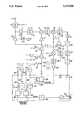
- the receive signal pathwill first be described.
- the signalis received on an aerial 1 and is subject to prefiltering in an RF filter 2 before being passed to an RF preamplifier 3.
- the RF preamplifieris switched between transmit and receive functions by means of a switch S1 in order to avoid overload of the input receive circuitry on transmit.
- the RF signalis further filtered by a premixer filter 4 before being applied to the input of the first mixer 5.
- the incoming signalis mixed with the output of the first local oscillator 6 whose output is buffered by buffer amplifiers 7 and 8.
- the oscillator 6is common to receive and transmit functions; on receive, its output frequency is 1021.975 MHz and on transmit its output frequency is 866.05 MHz.
- the operation of the oscillator 6is described in greater detail below.
- the buffer 8is used to mask out the movement of the oscillator 6 between transmit and receive by means of a switch S2 which is operable to switch the buffer off during this movement to prevent frequency originated sideband splatter.
- the oscillator 11is a crystal controlled oscillator comprising a 29.045 MHz crystal 12 and multiplier 13 which takes the 5th harmonic at 145.225 MHz for application to the second mixer 10.
- the output from the second mixer 10is filtered by a second IF filter 14, amplified by a second IF amplifier 15 and frequency discriminated by a discriminator 16 which detects the FSK data. This is further filtered by a post detection filter 17 and sliced by a data slicer 18 before being applied as fully shaped digital data to a data processor 19.
- the data processor 19is a multi-function unit which, inter alia, takes the output from the data slicer 18 and converts it back into an analog waveform for AF amplification and application to an earphone or loudspeaker (not shown).
- the transmit signal pathwill now be described.
- the data processor 19is used to prepare a digital data signal from the input analog (speech) waveform.
- the data output from data processor 19is applied to a shaping filter 20 where it is filtered before being applied to the crystal oscillator 11 to frequency modulate same.
- the f.m. deviationis +/-500 Hz which latter is multiplied by 5 in multiplier 13 to give an output deviation of +/-2.5 KHz.
- For transmit the oscillator 6is switched by means of a switch S3 to a frequency of 866.05 MHz.
- the output of oscillator 6is buffered, as before by buffer amplifier 8 and is amplified in power amplifier 22.
- the output of power amplifier 22is passed via filter 2 to aerial 1.
- An anti-splatter attenuator 23is switched into circuit on transmit by switch S4 and is operable to provide slow (10 ⁇ S) transients to the transmitter on/off switching action so as to reduce the splattering by the transmitter amplitude modulated sidebands into adjacent channels.
- Oscillator 6takes the form of a frequency switchable UHF voltage control oscillator (VCO).
- VCOvoltage control oscillator
- the oscillatorcan be switched by switch S3 to oscillate about a center frequency of 866.05 MHz for transmit, or 1021.975 MHz for receive.
- the oscillatoris frequency (FSK) modulated by the signal from oscillator 11 at a deviation of +/-15 KHz.
- the output frequency of the oscillator 6is controlled by a control voltage on a control line 24.
- the oscillator 6forms part of a mixer-type phase lock loop 21.
- the phase lock loopcomprises, in addition to oscillator 6, a mixer 25 which takes the output of the oscillator 6 and mixes it with a harmonic of the output signal of oscillator 11, a filter 26 which selects the appropriate difference frequency from mixer 25, an amplifier 27, and a phase/frequency detector 28.
- the reference frequency applied to detector 28is taken from one of oscillators 29 or 30 via a two-pole two-way switch S5, depending upon whether the transceiver is in transmit or receive mode.
- the control signal output of detector 28is passed via low pass loop filter 31 to the control input of VCO 6.
- the mixer 25 and filter 26are such as to generate a difference frequency at the output of filter 26 as follows:-
- the phase lock loop 21has to be fast acting in order firstly, to correctly track the frequency modulation applied to it at, typically, 80 Kbits/second, and secondly, to follow the rapid alternations between transmit and receive frequencies which occur during operation of the transceiver.
- This frequency changeover between transmit and receivehas to be accomplished in as short a time as possible, for example 10 ⁇ S, in order to allow a sufficient duration of steady reception or transmission.
- This rapid settling of the loopis achieved by using high reference frequencies in the range 3.3 to 7.4 MHz.
- reference oscillator 29has an output frequency of 5.4 MHz
- reference oscillator 30has an output frequency of 5.3 MHz.
- phase lock loop 21This allows the phase lock loop 21 to settle quickly because the period of the reference cycle is small (in the range 150 to 330 nS).
- a typical phase lock loopwill take of the order of 30 reference cycles to achieve phase lock, so the longer the period of the reference cycle, the longer will be the time taken to stabilise the loop.
- a long reference periodsuch as 10 ⁇ S (corresponding to a 100 KHz reference frequency) is not a practical proposition if, as in the present case, a 10 ⁇ S settle time is to be realized.
- the loop 21is of the mixer type in which the controlled frequency is offset from the reference frequency, or a multiple thereof, by a further frequency. This distinguishes from the more common divider type loop in which the controlled frequency is a multiple of the reference frequency.
- the VCO 6is offset from the reference frequency by either the sixth harmonic of 145.225 MHz on transmit, (i.e. 871.35 MHz), or with the seventh harmonic on receive (i.e. 1016.575 MHz) in the mixer 25.
- These harmonic frequenciesare generated in the non-linear mixing process in mixer 25. No preselection of harmonics is necessary (though possible) for the proper function as only the harmonic close enough to the approximate unlocked frequency of the VCO 6 is able to produce a beat frequency in the range 3.3 to 7.4 MHz which is selected by the mixer filter 26.
- the actual reference frequency used and the sense of presentation to the detector 28is determined by whether the transceiver is in transmit or receive.
- the sense and actual frequencyare changed between transmit and receive by means of switch S5 so that an offset of the sum of the reference frequencies plus the difference between the adjacent harmonics of 145.225 MHz is generated.
- the reference frequenciesare always arranged here to add up to 10.7 MHz and the difference between adjacent harmonics is of course the original frequency of 145.225 MHz so that the offset between the transmit frequency and the receive frequency is always 155.925 MHz (or 134.525 MHz if the senses of the transmit and receive loops had been reversed).
- This frequency of 155.925 MHzthus becomes the first IF in the dual conversion receiver section.
- the first IF of 155.925 MHzis converted down to the second IF of 10.7 MHz by mixing with the 145.225 MHz second local oscillator frequency derived from the fifth harmonic of the output of crystal oscillator 11.
- the two reference frequency oscillatorstake the form of VCO's 29, 30 which are locked to multiples of a low reference frequency of 100 KHz by respective phase lock loops 32, 33 using programmable dividers 34, 35.
- the phase lock loop 32comprises, in addition to oscillator 29, the divider 34, loop filter 36 and phase/frequency detector 38.
- the loop 33comprises oscillator 30, divider 35, loop filter 39 and phase/frequency detector 42. Note that the division ratios are arranged to total 107 so that the derived reference frequencies always add up to 10.7 MHz.
- the 100 KHz reference frequency for loops 32, 33is derived by fixed division by 72 in a divider 40 from a local clock frequency of 7.2 MHz generated by a crystal oscillator 41.
- the switch S5selects as the two inputs to the phase/frequency detector 28 the output from amplifier 27 together with one of the outputs from oscillator 29 or 30, depending upon whether the transceiver is in receive mode or transmit mode.
- the switchis also connected in such a way as to reverse the sense of the input connection to detector 28 according to which mode is selected.
- Meansare provided for switching the switches S1, S3, S4 and S5 at the duplex changeover rate--for example 1.3 KHz to effect alternation between the transmit and receive functions. It has been found that the above-described transceiver is capable of rapidly and repeatedly alternating between transmit and receive functions and is therefore well suited to time division duplex operation. The transceiver is able to meet the target of 10 ⁇ S changeover time and is thus well capable of operating within existing standards of an approximately 1.3 KHz transmit/receive alternation frequency, corresponding to a 375 ⁇ S transmit/receive period, this comprising a data portion of 312.5 ⁇ S duration, an identity data portion, and a changeover portion.
Landscapes
- Engineering & Computer Science (AREA)
- Computer Networks & Wireless Communication (AREA)
- Signal Processing (AREA)
- Transceivers (AREA)
- Agricultural Chemicals And Associated Chemicals (AREA)
- Organic Low-Molecular-Weight Compounds And Preparation Thereof (AREA)
- Burglar Alarm Systems (AREA)
- Weting (AREA)
- Optical Communication System (AREA)
- Photoreceptors In Electrophotography (AREA)
- Lock And Its Accessories (AREA)
- Transmitters (AREA)
Abstract
Description
Claims (12)
Applications Claiming Priority (2)
| Application Number | Priority Date | Filing Date | Title |
|---|---|---|---|
| GB888806194AGB8806194D0 (en) | 1988-03-16 | 1988-03-16 | Transceivers |
| GB8806194 | 1988-03-16 |
Publications (1)
| Publication Number | Publication Date |
|---|---|
| US5123008Atrue US5123008A (en) | 1992-06-16 |
Family
ID=10633506
Family Applications (1)
| Application Number | Title | Priority Date | Filing Date |
|---|---|---|---|
| US07/322,059Expired - LifetimeUS5123008A (en) | 1988-03-16 | 1989-03-13 | Single frequency time division duplex transceiver |
Country Status (9)
| Country | Link |
|---|---|
| US (1) | US5123008A (en) |
| EP (1) | EP0333419B1 (en) |
| JP (1) | JP3063089B2 (en) |
| AT (1) | ATE117860T1 (en) |
| CA (1) | CA1310067C (en) |
| DE (1) | DE68920761T2 (en) |
| FI (1) | FI891221A7 (en) |
| GB (1) | GB8806194D0 (en) |
| NO (1) | NO891033L (en) |
Cited By (48)
| Publication number | Priority date | Publication date | Assignee | Title |
|---|---|---|---|---|
| WO1993009606A1 (en)* | 1991-11-04 | 1993-05-13 | Motorola, Inc. | Oscillator frequency divide-down transmit offset scheme for reducing self-quieting |
| US5239689A (en)* | 1990-10-25 | 1993-08-24 | Sony Corporation | Transmitter/receiver apparatus with common oscillator that changes frequency between transmitting and received operations |
| WO1993021693A1 (en)* | 1992-04-14 | 1993-10-28 | Motorola, Inc. | Frequency offset method and apparatus for use in a transceiver |
| US5267233A (en)* | 1990-11-15 | 1993-11-30 | Grundig E.M.V. | Radio set for an FDM-TDM-radio transmission set |
| US5309429A (en)* | 1991-02-22 | 1994-05-03 | Sony Corporation | Transmitter-receiver |
| US5319799A (en)* | 1991-01-25 | 1994-06-07 | Matsushita Electric Industrial Co., Ltd. | Signal oscillation method for time-division duplex radio transceiver and apparatus using the same |
| US5327582A (en)* | 1992-01-24 | 1994-07-05 | Motorola, Inc. | Wideband wireless communications receiver |
| US5339309A (en)* | 1991-12-27 | 1994-08-16 | Sony Corporation | Transmitter-receiver |
| DE4414350A1 (en)* | 1993-04-30 | 1994-11-03 | Prince Corp | Learnable transmitter |
| US5442340A (en)* | 1988-12-05 | 1995-08-15 | Prince Corporation | Trainable RF transmitter including attenuation control |
| US5444865A (en)* | 1991-04-01 | 1995-08-22 | Motorola, Inc. | Generating transmit injection from receiver first and second injections |
| US5446770A (en)* | 1993-03-31 | 1995-08-29 | Matsushita Electric Industrial Co., Ltd. | Time division duplex transceiver |
| US5479155A (en)* | 1988-12-05 | 1995-12-26 | Prince Corporation | Vehicle accessory trainable transmitter |
| US5511236A (en)* | 1993-12-07 | 1996-04-23 | National Semiconductor Corporation | Half duplex RF transceiver |
| US5583485A (en)* | 1988-12-05 | 1996-12-10 | Prince Corporation | Trainable transmitter and receiver |
| US5598405A (en)* | 1994-01-25 | 1997-01-28 | Alps Electric Co., Ltd. | Time division multiple access time division duplex type transmitter-receiver |
| US5612947A (en)* | 1994-06-30 | 1997-03-18 | Hyundai Electronics Industries Co., Ltd. | Apparatus and method for fast changeover in duplex system |
| US5619190A (en)* | 1994-03-11 | 1997-04-08 | Prince Corporation | Trainable transmitter with interrupt signal generator |
| US5661804A (en)* | 1995-06-27 | 1997-08-26 | Prince Corporation | Trainable transceiver capable of learning variable codes |
| US5686903A (en)* | 1995-05-19 | 1997-11-11 | Prince Corporation | Trainable RF transceiver |
| US5689819A (en)* | 1995-06-05 | 1997-11-18 | Mitsubishi Denki Kabushiki Kaisha | Transmitter-receiver |
| US5699055A (en)* | 1995-05-19 | 1997-12-16 | Prince Corporation | Trainable transceiver and method for learning an activation signal that remotely actuates a device |
| US5699054A (en)* | 1995-05-19 | 1997-12-16 | Prince Corporation | Trainable transceiver including a dynamically tunable antenna |
| US5708415A (en)* | 1988-12-05 | 1998-01-13 | Prince Corporation | Electrical control system for vehicle options |
| US5793300A (en)* | 1993-03-15 | 1998-08-11 | Prince Corporation | Trainable RF receiver for remotely controlling household appliances |
| US5828695A (en)* | 1991-06-03 | 1998-10-27 | British Telecommunications Public Limited Company | QAM system in which the constellation is modified in accordance with channel quality |
| US5854593A (en)* | 1996-07-26 | 1998-12-29 | Prince Corporation | Fast scan trainable transmitter |
| US5903326A (en) | 1995-11-20 | 1999-05-11 | Prince Corporation | Trainable RF system for remotely controlling household appliances |
| US6088414A (en)* | 1997-12-18 | 2000-07-11 | Alcatel Usa Sourcing, L.P. | Method of frequency and phase locking in a plurality of temporal frames |
| US6118836A (en)* | 1997-12-18 | 2000-09-12 | Alcatel Usa Sourcing L.P. | Frequency and phase locking apparatus |
| US6218909B1 (en) | 1998-10-23 | 2001-04-17 | Texas Insturments Israel Ltd. | Multiple frequency band voltage controlled oscillator |
| US20030112121A1 (en)* | 2001-12-19 | 2003-06-19 | Lear Corporation | Universal garage door operating system and method |
| US20040185781A1 (en)* | 1999-10-21 | 2004-09-23 | Shervin Moloudi | System and method for reducing phase noise |
| US20050024229A1 (en)* | 2003-07-30 | 2005-02-03 | Lear Corporation | Programmable appliance remote control |
| US20050024254A1 (en)* | 2003-07-30 | 2005-02-03 | Lear Corporation | Radio relay appliance activation |
| US20050026602A1 (en)* | 2003-07-30 | 2005-02-03 | Lear Corporation | User-assisted programmable appliance control |
| US20050024184A1 (en)* | 2003-07-30 | 2005-02-03 | Lear Corporation | Wireless appliance activation transceiver |
| US20050024255A1 (en)* | 2003-07-30 | 2005-02-03 | Lear Corporation | Bus-based appliance remote control |
| US20050136846A1 (en)* | 2003-12-23 | 2005-06-23 | Samsung Electronics Co., Ltd. | RF transceiver |
| US7084781B2 (en) | 2003-07-30 | 2006-08-01 | Lear Corporation | Programmable vehicle-based appliance remote control |
| US7116242B2 (en) | 2002-11-27 | 2006-10-03 | Lear Corporation | Programmable transmitter and receiver including digital radio frequency memory |
| US7120430B2 (en) | 2003-07-30 | 2006-10-10 | Lear Corporation | Programmable interoperable appliance remote control |
| US7161466B2 (en) | 2003-07-30 | 2007-01-09 | Lear Corporation | Remote control automatic appliance activation |
| US7269416B2 (en) | 2003-07-30 | 2007-09-11 | Lear Corporation | Universal vehicle based garage door opener control system and method |
| US20070236328A1 (en)* | 2006-04-03 | 2007-10-11 | Lear Corporation | All trinary rolling code generation method and system |
| US20070264955A1 (en)* | 2006-05-15 | 2007-11-15 | Jr-Shian Tsai | Methods and apparatus for a paging mechanism within wireless networks including multiple access points |
| US20100056044A1 (en)* | 2008-08-29 | 2010-03-04 | Brady Vernon T | Radio frequency (rf) transceiver |
| US8718563B2 (en) | 1999-10-21 | 2014-05-06 | Broadcom Corporation | System and method for signal limiting |
Families Citing this family (12)
| Publication number | Priority date | Publication date | Assignee | Title |
|---|---|---|---|---|
| US5222253A (en)* | 1990-08-29 | 1993-06-22 | Motorola, Inc. | Transient suppression circuit for a time domain duplex transceiver |
| DE4041643A1 (en)* | 1990-12-22 | 1992-07-02 | Grundig Emv | Cordless telephone allowing for alternate two=way traffic - reduces frequency spacing of duplex channels at main station as relay between two mobile stations |
| JPH05227054A (en)* | 1992-02-15 | 1993-09-03 | Mitsubishi Electric Corp | Radio set |
| US5453714A (en)* | 1993-03-10 | 1995-09-26 | National Semiconductor Corporation | Binary FM demodulator with self-adjusting resonant operating frequency according to demodulated binary output signal duty cycle |
| EP0688446A1 (en)* | 1993-03-10 | 1995-12-27 | National Semiconductor Corporation | Radio frequency telecommunications transceiver |
| WO1994027376A1 (en)* | 1993-05-06 | 1994-11-24 | Motorola Inc. | Tunable filter circuit and method therefor |
| KR100219709B1 (en)* | 1994-03-15 | 1999-09-01 | 윤종용 | Signal processing circuits for digital radio communication system |
| KR0143023B1 (en)* | 1994-08-03 | 1998-08-01 | 김광호 | Digital telephone |
| JPH0918378A (en)* | 1995-07-03 | 1997-01-17 | Matsushita Electric Ind Co Ltd | Radio circuit |
| US6735418B1 (en)* | 1999-05-24 | 2004-05-11 | Intel Corporation | Antenna interface |
| US7398068B2 (en) | 2003-05-05 | 2008-07-08 | Marvell International Ltd. | Dual antenna system having one phase lock loop |
| JP5856291B2 (en)* | 2011-05-30 | 2016-02-09 | アコネール アクティエボラーグ | Transceiver module |
Citations (12)
| Publication number | Priority date | Publication date | Assignee | Title |
|---|---|---|---|---|
| US3983484A (en)* | 1974-12-06 | 1976-09-28 | Nihon Dengyo Co., Ltd. | Multichannel signal transmitting and receiving apparatus |
| US4037158A (en)* | 1974-10-07 | 1977-07-19 | Motorola, Inc. | Two-way FM radio system operating on a single channel and providing simulated duplex operation |
| US4238850A (en)* | 1977-12-01 | 1980-12-09 | International Standard Electric Corporation | Transmitter/receiver for single channel duplex communication system |
| US4430756A (en)* | 1982-02-22 | 1984-02-07 | General Electric Company | Oscillator control circuit |
| US4520474A (en)* | 1983-12-05 | 1985-05-28 | Motorola, Inc. | Duplex communication transceiver with modulation cancellation |
| US4525835A (en)* | 1981-10-13 | 1985-06-25 | International Standard Electric Corporation | Duplex radio system utilizing time compression expansion |
| US4542531A (en)* | 1982-03-18 | 1985-09-17 | Nippon Electric Co., Ltd. | Radio transmitter/receivers with non interferring local oscillator frequency |
| US4633511A (en)* | 1983-08-24 | 1986-12-30 | Toyo Communication Equipment Co. | Signal transmission and reception system |
| US4644524A (en)* | 1985-01-22 | 1987-02-17 | Emery David L | Simultaneous communication system using time delays |
| GB2188212A (en)* | 1986-03-21 | 1987-09-23 | British Telecomm | Single frequency transceiver |
| GB2196514A (en)* | 1986-08-21 | 1988-04-27 | Uldeco Limited | Radio communications |
| US4903257A (en)* | 1987-05-27 | 1990-02-20 | Fujitsu Limited | Digital two-way radio-communication system using single frequency |
Family Cites Families (2)
| Publication number | Priority date | Publication date | Assignee | Title |
|---|---|---|---|---|
| JPS5291637A (en)* | 1976-01-28 | 1977-08-02 | Toshiba Corp | Frequency conversion system |
| JPS52122409A (en)* | 1976-04-07 | 1977-10-14 | Saibanetsuto Kougiyou Kk | Phase locked loop transmitter*receiver |
- 1988
- 1988-03-16GBGB888806194Apatent/GB8806194D0/enactivePending
- 1989
- 1989-03-10NONO89891033Apatent/NO891033L/enunknown
- 1989-03-13USUS07/322,059patent/US5123008A/ennot_activeExpired - Lifetime
- 1989-03-14ATAT89302467Tpatent/ATE117860T1/ennot_activeIP Right Cessation
- 1989-03-14EPEP89302467Apatent/EP0333419B1/ennot_activeExpired - Lifetime
- 1989-03-14DEDE68920761Tpatent/DE68920761T2/ennot_activeExpired - Lifetime
- 1989-03-15FIFI891221Apatent/FI891221A7/ennot_activeApplication Discontinuation
- 1989-03-15CACA000593719Apatent/CA1310067C/ennot_activeExpired - Lifetime
- 1989-03-16JPJP1062337Apatent/JP3063089B2/ennot_activeExpired - Lifetime
Patent Citations (12)
| Publication number | Priority date | Publication date | Assignee | Title |
|---|---|---|---|---|
| US4037158A (en)* | 1974-10-07 | 1977-07-19 | Motorola, Inc. | Two-way FM radio system operating on a single channel and providing simulated duplex operation |
| US3983484A (en)* | 1974-12-06 | 1976-09-28 | Nihon Dengyo Co., Ltd. | Multichannel signal transmitting and receiving apparatus |
| US4238850A (en)* | 1977-12-01 | 1980-12-09 | International Standard Electric Corporation | Transmitter/receiver for single channel duplex communication system |
| US4525835A (en)* | 1981-10-13 | 1985-06-25 | International Standard Electric Corporation | Duplex radio system utilizing time compression expansion |
| US4430756A (en)* | 1982-02-22 | 1984-02-07 | General Electric Company | Oscillator control circuit |
| US4542531A (en)* | 1982-03-18 | 1985-09-17 | Nippon Electric Co., Ltd. | Radio transmitter/receivers with non interferring local oscillator frequency |
| US4633511A (en)* | 1983-08-24 | 1986-12-30 | Toyo Communication Equipment Co. | Signal transmission and reception system |
| US4520474A (en)* | 1983-12-05 | 1985-05-28 | Motorola, Inc. | Duplex communication transceiver with modulation cancellation |
| US4644524A (en)* | 1985-01-22 | 1987-02-17 | Emery David L | Simultaneous communication system using time delays |
| GB2188212A (en)* | 1986-03-21 | 1987-09-23 | British Telecomm | Single frequency transceiver |
| GB2196514A (en)* | 1986-08-21 | 1988-04-27 | Uldeco Limited | Radio communications |
| US4903257A (en)* | 1987-05-27 | 1990-02-20 | Fujitsu Limited | Digital two-way radio-communication system using single frequency |
Cited By (73)
| Publication number | Priority date | Publication date | Assignee | Title |
|---|---|---|---|---|
| US5708415A (en)* | 1988-12-05 | 1998-01-13 | Prince Corporation | Electrical control system for vehicle options |
| US5479155A (en)* | 1988-12-05 | 1995-12-26 | Prince Corporation | Vehicle accessory trainable transmitter |
| US5583485A (en)* | 1988-12-05 | 1996-12-10 | Prince Corporation | Trainable transmitter and receiver |
| US5442340A (en)* | 1988-12-05 | 1995-08-15 | Prince Corporation | Trainable RF transmitter including attenuation control |
| US5614891A (en)* | 1988-12-05 | 1997-03-25 | Prince Corporation | Vehicle accessory trainable transmitter |
| US5646701A (en)* | 1990-08-14 | 1997-07-08 | Prince Corporation | Trainable transmitter with transmit/receive switch |
| US5239689A (en)* | 1990-10-25 | 1993-08-24 | Sony Corporation | Transmitter/receiver apparatus with common oscillator that changes frequency between transmitting and received operations |
| US5267233A (en)* | 1990-11-15 | 1993-11-30 | Grundig E.M.V. | Radio set for an FDM-TDM-radio transmission set |
| US5319799A (en)* | 1991-01-25 | 1994-06-07 | Matsushita Electric Industrial Co., Ltd. | Signal oscillation method for time-division duplex radio transceiver and apparatus using the same |
| US5309429A (en)* | 1991-02-22 | 1994-05-03 | Sony Corporation | Transmitter-receiver |
| US5444865A (en)* | 1991-04-01 | 1995-08-22 | Motorola, Inc. | Generating transmit injection from receiver first and second injections |
| US5828695A (en)* | 1991-06-03 | 1998-10-27 | British Telecommunications Public Limited Company | QAM system in which the constellation is modified in accordance with channel quality |
| US5276915A (en)* | 1991-11-04 | 1994-01-04 | Motorola, Inc. | Transceiver having a divide-down transmit offset scheme |
| WO1993009606A1 (en)* | 1991-11-04 | 1993-05-13 | Motorola, Inc. | Oscillator frequency divide-down transmit offset scheme for reducing self-quieting |
| US5339309A (en)* | 1991-12-27 | 1994-08-16 | Sony Corporation | Transmitter-receiver |
| US5327582A (en)* | 1992-01-24 | 1994-07-05 | Motorola, Inc. | Wideband wireless communications receiver |
| WO1993021693A1 (en)* | 1992-04-14 | 1993-10-28 | Motorola, Inc. | Frequency offset method and apparatus for use in a transceiver |
| US5793300A (en)* | 1993-03-15 | 1998-08-11 | Prince Corporation | Trainable RF receiver for remotely controlling household appliances |
| US5903226A (en)* | 1993-03-15 | 1999-05-11 | Prince Corporation | Trainable RF system for remotely controlling household appliances |
| US5446770A (en)* | 1993-03-31 | 1995-08-29 | Matsushita Electric Industrial Co., Ltd. | Time division duplex transceiver |
| DE4414350B4 (en)* | 1993-04-30 | 2005-07-21 | Prince Corp., Holland | Learning capable transmitter |
| DE4414350A1 (en)* | 1993-04-30 | 1994-11-03 | Prince Corp | Learnable transmitter |
| US5511236A (en)* | 1993-12-07 | 1996-04-23 | National Semiconductor Corporation | Half duplex RF transceiver |
| US5598405A (en)* | 1994-01-25 | 1997-01-28 | Alps Electric Co., Ltd. | Time division multiple access time division duplex type transmitter-receiver |
| US5627529A (en)* | 1994-03-11 | 1997-05-06 | Prince Corporation | Vehicle control system with trainable transceiver |
| US5619190A (en)* | 1994-03-11 | 1997-04-08 | Prince Corporation | Trainable transmitter with interrupt signal generator |
| US5612947A (en)* | 1994-06-30 | 1997-03-18 | Hyundai Electronics Industries Co., Ltd. | Apparatus and method for fast changeover in duplex system |
| US5686903A (en)* | 1995-05-19 | 1997-11-11 | Prince Corporation | Trainable RF transceiver |
| US5699055A (en)* | 1995-05-19 | 1997-12-16 | Prince Corporation | Trainable transceiver and method for learning an activation signal that remotely actuates a device |
| US5699054A (en)* | 1995-05-19 | 1997-12-16 | Prince Corporation | Trainable transceiver including a dynamically tunable antenna |
| US5689819A (en)* | 1995-06-05 | 1997-11-18 | Mitsubishi Denki Kabushiki Kaisha | Transmitter-receiver |
| US5661804A (en)* | 1995-06-27 | 1997-08-26 | Prince Corporation | Trainable transceiver capable of learning variable codes |
| US5903326A (en) | 1995-11-20 | 1999-05-11 | Prince Corporation | Trainable RF system for remotely controlling household appliances |
| US5854593A (en)* | 1996-07-26 | 1998-12-29 | Prince Corporation | Fast scan trainable transmitter |
| US6088414A (en)* | 1997-12-18 | 2000-07-11 | Alcatel Usa Sourcing, L.P. | Method of frequency and phase locking in a plurality of temporal frames |
| US6118836A (en)* | 1997-12-18 | 2000-09-12 | Alcatel Usa Sourcing L.P. | Frequency and phase locking apparatus |
| US6218909B1 (en) | 1998-10-23 | 2001-04-17 | Texas Insturments Israel Ltd. | Multiple frequency band voltage controlled oscillator |
| US20040185781A1 (en)* | 1999-10-21 | 2004-09-23 | Shervin Moloudi | System and method for reducing phase noise |
| US7933555B2 (en)* | 1999-10-21 | 2011-04-26 | Broadcom Corporation | System and method for reducing phase noise |
| US8718563B2 (en) | 1999-10-21 | 2014-05-06 | Broadcom Corporation | System and method for signal limiting |
| US7135957B2 (en) | 2001-12-19 | 2006-11-14 | Lear Corporation | Universal garage door operating system and method |
| US20030112121A1 (en)* | 2001-12-19 | 2003-06-19 | Lear Corporation | Universal garage door operating system and method |
| US7167076B2 (en) | 2001-12-19 | 2007-01-23 | Lear Corporation | Universal garage door operating system and method |
| US20060038656A1 (en)* | 2001-12-19 | 2006-02-23 | Lear Corporation | Universal garage door operating system and method |
| US7116242B2 (en) | 2002-11-27 | 2006-10-03 | Lear Corporation | Programmable transmitter and receiver including digital radio frequency memory |
| US7183941B2 (en) | 2003-07-30 | 2007-02-27 | Lear Corporation | Bus-based appliance remote control |
| US20050026601A1 (en)* | 2003-07-30 | 2005-02-03 | Lear Corporation | User-assisted programmable appliance control |
| US7039397B2 (en) | 2003-07-30 | 2006-05-02 | Lear Corporation | User-assisted programmable appliance control |
| US7050794B2 (en) | 2003-07-30 | 2006-05-23 | Lear Corporation | User-assisted programmable appliance control |
| US7068181B2 (en) | 2003-07-30 | 2006-06-27 | Lear Corporation | Programmable appliance remote control |
| US7084781B2 (en) | 2003-07-30 | 2006-08-01 | Lear Corporation | Programmable vehicle-based appliance remote control |
| US7088218B2 (en) | 2003-07-30 | 2006-08-08 | Lear Corporation | Wireless appliance activation transceiver |
| US20050024255A1 (en)* | 2003-07-30 | 2005-02-03 | Lear Corporation | Bus-based appliance remote control |
| US7120430B2 (en) | 2003-07-30 | 2006-10-10 | Lear Corporation | Programmable interoperable appliance remote control |
| US20050024229A1 (en)* | 2003-07-30 | 2005-02-03 | Lear Corporation | Programmable appliance remote control |
| US7161466B2 (en) | 2003-07-30 | 2007-01-09 | Lear Corporation | Remote control automatic appliance activation |
| US20050024184A1 (en)* | 2003-07-30 | 2005-02-03 | Lear Corporation | Wireless appliance activation transceiver |
| US7183940B2 (en) | 2003-07-30 | 2007-02-27 | Lear Corporation | Radio relay appliance activation |
| US20050024254A1 (en)* | 2003-07-30 | 2005-02-03 | Lear Corporation | Radio relay appliance activation |
| US7269416B2 (en) | 2003-07-30 | 2007-09-11 | Lear Corporation | Universal vehicle based garage door opener control system and method |
| US20050026602A1 (en)* | 2003-07-30 | 2005-02-03 | Lear Corporation | User-assisted programmable appliance control |
| US7855633B2 (en) | 2003-07-30 | 2010-12-21 | Lear Corporation | Remote control automatic appliance activation |
| US7447498B2 (en) | 2003-07-30 | 2008-11-04 | Lear Corporation | User-assisted programmable appliance control |
| US7489922B2 (en) | 2003-07-30 | 2009-02-10 | Lear Corporation | User-assisted programmable appliance control |
| US7812739B2 (en) | 2003-07-30 | 2010-10-12 | Lear Corporation | Programmable appliance remote control |
| US7760071B2 (en) | 2003-07-30 | 2010-07-20 | Lear Corporation | Appliance remote control having separated user control and transmitter modules remotely located from and directly connected to one another |
| US20050136846A1 (en)* | 2003-12-23 | 2005-06-23 | Samsung Electronics Co., Ltd. | RF transceiver |
| US7589613B2 (en) | 2006-04-03 | 2009-09-15 | Lear Corporation | Trinary to trinary rolling code generation method and system |
| US20070236328A1 (en)* | 2006-04-03 | 2007-10-11 | Lear Corporation | All trinary rolling code generation method and system |
| US7567785B2 (en)* | 2006-05-15 | 2009-07-28 | Intel Corporation | Methods and apparatus for a paging mechanism within wireless networks including multiple access points |
| US20070264955A1 (en)* | 2006-05-15 | 2007-11-15 | Jr-Shian Tsai | Methods and apparatus for a paging mechanism within wireless networks including multiple access points |
| US20100056044A1 (en)* | 2008-08-29 | 2010-03-04 | Brady Vernon T | Radio frequency (rf) transceiver |
| US8417192B2 (en)* | 2008-08-29 | 2013-04-09 | Lockheed Martin Corporation | Radio frequency (RF) transceiver |
Also Published As
| Publication number | Publication date |
|---|---|
| CA1310067C (en) | 1992-11-10 |
| EP0333419A3 (en) | 1990-12-27 |
| GB8806194D0 (en) | 1988-04-13 |
| DE68920761T2 (en) | 1995-05-24 |
| NO891033D0 (en) | 1989-03-10 |
| DE68920761D1 (en) | 1995-03-09 |
| JP3063089B2 (en) | 2000-07-12 |
| ATE117860T1 (en) | 1995-02-15 |
| FI891221A0 (en) | 1989-03-15 |
| NO891033L (en) | 1989-09-18 |
| EP0333419B1 (en) | 1995-01-25 |
| FI891221A7 (en) | 1989-09-17 |
| JPH01303814A (en) | 1989-12-07 |
| EP0333419A2 (en) | 1989-09-20 |
Similar Documents
| Publication | Publication Date | Title |
|---|---|---|
| US5123008A (en) | Single frequency time division duplex transceiver | |
| US6175746B1 (en) | Multiband mobile unit communication apparatus | |
| US5444865A (en) | Generating transmit injection from receiver first and second injections | |
| US5511236A (en) | Half duplex RF transceiver | |
| US5428824A (en) | Radio transceiver capable of avoiding intermodulation distortion | |
| US5825813A (en) | Transceiver signal processor for digital cordless communication apparatus | |
| KR0143023B1 (en) | Digital telephone | |
| US5408201A (en) | Frequency synthesizer using three subfrequency synthesizers for generating two different frequencies | |
| US6415001B1 (en) | System and process for shared frequency source multi-band transmitters and receivers | |
| EP0932938B1 (en) | Arrangement in a communication system | |
| US6034990A (en) | Digital radio transmission and reception system applying a direct modulation and demodulation method | |
| JPH0151100B2 (en) | ||
| EP0529767B1 (en) | Digital radio communication apparatus | |
| JP3255054B2 (en) | Digital mobile phone | |
| US5537676A (en) | Method of receiving data signals in a radio transceiver using low cost components | |
| EP1466418B1 (en) | Transceiver with multi-state direct digital synthesizer driven phase locked loop | |
| JPH05259934A (en) | Transmitting/receiving device | |
| HUT73702A (en) | A communication device for computer networks, particularly of the cordless type | |
| JPH0799448A (en) | PLL frequency synthesizer circuit | |
| KR910005652B1 (en) | Simultaneous bidirectional fm transmitter-receiver | |
| KR950007495B1 (en) | High Frequency Signal Processing Device of Digital Cordless Telephone | |
| JPH01270418A (en) | Simultaneous bidirectional fm transmitter-receiver | |
| KR0143727B1 (en) | Frequency Oscillator of Satellite Communication System | |
| JPH02112323A (en) | Radio communication equipment | |
| EP0488476A2 (en) | Radio transceiver |
Legal Events
| Date | Code | Title | Description |
|---|---|---|---|
| AS | Assignment | Owner name:SHAYE COMMUNICATIONS LIMITED,, ENGLAND Free format text:ASSIGNMENT OF ASSIGNORS INTEREST.;ASSIGNOR:BEESLEY, GRAHAM E.;REEL/FRAME:005053/0981 Effective date:19890223 | |
| STCF | Information on status: patent grant | Free format text:PATENTED CASE | |
| FEPP | Fee payment procedure | Free format text:PAYOR NUMBER ASSIGNED (ORIGINAL EVENT CODE: ASPN); ENTITY STATUS OF PATENT OWNER: LARGE ENTITY | |
| FPAY | Fee payment | Year of fee payment:4 | |
| FEPP | Fee payment procedure | Free format text:PAYER NUMBER DE-ASSIGNED (ORIGINAL EVENT CODE: RMPN); ENTITY STATUS OF PATENT OWNER: LARGE ENTITY Free format text:PAYOR NUMBER ASSIGNED (ORIGINAL EVENT CODE: ASPN); ENTITY STATUS OF PATENT OWNER: LARGE ENTITY | |
| FPAY | Fee payment | Year of fee payment:8 | |
| AS | Assignment | Owner name:AVAYA TECHNOLOGY CORP., NEW JERSEY Free format text:ASSIGNMENT OF ASSIGNORS INTEREST;ASSIGNOR:LUCENT TECHNOLOGIES INC.;REEL/FRAME:012691/0572 Effective date:20000929 | |
| AS | Assignment | Owner name:BANK OF NEW YORK, THE, NEW YORK Free format text:SECURITY INTEREST;ASSIGNOR:AVAYA TECHNOLOGY CORP.;REEL/FRAME:012762/0160 Effective date:20020405 | |
| FEPP | Fee payment procedure | Free format text:PAT HOLDER NO LONGER CLAIMS SMALL ENTITY STATUS, ENTITY STATUS SET TO UNDISCOUNTED (ORIGINAL EVENT CODE: STOL); ENTITY STATUS OF PATENT OWNER: LARGE ENTITY | |
| REFU | Refund | Free format text:REFUND - PAYMENT OF MAINTENANCE FEE, 12TH YR, SMALL ENTITY (ORIGINAL EVENT CODE: R2553); ENTITY STATUS OF PATENT OWNER: LARGE ENTITY | |
| FPAY | Fee payment | Year of fee payment:12 | |
| AS | Assignment | Owner name:AVAYA INC., NEW JERSEY Free format text:REASSIGNMENT;ASSIGNOR:AVAYA TECHNOLOGY LLC;REEL/FRAME:021158/0290 Effective date:20080625 | |
| AS | Assignment | Owner name:AVAYA TECHNOLOGY LLC, NEW JERSEY Free format text:CONVERSION FROM CORP TO LLC;ASSIGNOR:AVAYA TECHNOLOGY CORP.;REEL/FRAME:022071/0420 Effective date:20051004 |