US5122893A - Bi-directional optical transceiver - Google Patents
Bi-directional optical transceiverDownload PDFInfo
- Publication number
- US5122893A US5122893AUS07/633,219US63321990AUS5122893AUS 5122893 AUS5122893 AUS 5122893AUS 63321990 AUS63321990 AUS 63321990AUS 5122893 AUS5122893 AUS 5122893A
- Authority
- US
- United States
- Prior art keywords
- optical
- electrical signal
- optical signal
- electrical
- receiving
- Prior art date
- Legal status (The legal status is an assumption and is not a legal conclusion. Google has not performed a legal analysis and makes no representation as to the accuracy of the status listed.)
- Expired - Lifetime
Links
Images


Classifications
- H—ELECTRICITY
- H04—ELECTRIC COMMUNICATION TECHNIQUE
- H04B—TRANSMISSION
- H04B10/00—Transmission systems employing electromagnetic waves other than radio-waves, e.g. infrared, visible or ultraviolet light, or employing corpuscular radiation, e.g. quantum communication
- H04B10/40—Transceivers
- H—ELECTRICITY
- H01—ELECTRIC ELEMENTS
- H01L—SEMICONDUCTOR DEVICES NOT COVERED BY CLASS H10
- H01L2224/00—Indexing scheme for arrangements for connecting or disconnecting semiconductor or solid-state bodies and methods related thereto as covered by H01L24/00
- H01L2224/01—Means for bonding being attached to, or being formed on, the surface to be connected, e.g. chip-to-package, die-attach, "first-level" interconnects; Manufacturing methods related thereto
- H01L2224/42—Wire connectors; Manufacturing methods related thereto
- H01L2224/47—Structure, shape, material or disposition of the wire connectors after the connecting process
- H01L2224/48—Structure, shape, material or disposition of the wire connectors after the connecting process of an individual wire connector
- H01L2224/481—Disposition
- H01L2224/48135—Connecting between different semiconductor or solid-state bodies, i.e. chip-to-chip
- H01L2224/48137—Connecting between different semiconductor or solid-state bodies, i.e. chip-to-chip the bodies being arranged next to each other, e.g. on a common substrate
- H—ELECTRICITY
- H01—ELECTRIC ELEMENTS
- H01L—SEMICONDUCTOR DEVICES NOT COVERED BY CLASS H10
- H01L2224/00—Indexing scheme for arrangements for connecting or disconnecting semiconductor or solid-state bodies and methods related thereto as covered by H01L24/00
- H01L2224/01—Means for bonding being attached to, or being formed on, the surface to be connected, e.g. chip-to-package, die-attach, "first-level" interconnects; Manufacturing methods related thereto
- H01L2224/42—Wire connectors; Manufacturing methods related thereto
- H01L2224/47—Structure, shape, material or disposition of the wire connectors after the connecting process
- H01L2224/48—Structure, shape, material or disposition of the wire connectors after the connecting process of an individual wire connector
- H01L2224/481—Disposition
- H01L2224/48151—Connecting between a semiconductor or solid-state body and an item not being a semiconductor or solid-state body, e.g. chip-to-substrate, chip-to-passive
- H01L2224/48221—Connecting between a semiconductor or solid-state body and an item not being a semiconductor or solid-state body, e.g. chip-to-substrate, chip-to-passive the body and the item being stacked
- H01L2224/48245—Connecting between a semiconductor or solid-state body and an item not being a semiconductor or solid-state body, e.g. chip-to-substrate, chip-to-passive the body and the item being stacked the item being metallic
- H01L2224/48247—Connecting between a semiconductor or solid-state body and an item not being a semiconductor or solid-state body, e.g. chip-to-substrate, chip-to-passive the body and the item being stacked the item being metallic connecting the wire to a bond pad of the item
- H—ELECTRICITY
- H01—ELECTRIC ELEMENTS
- H01L—SEMICONDUCTOR DEVICES NOT COVERED BY CLASS H10
- H01L2224/00—Indexing scheme for arrangements for connecting or disconnecting semiconductor or solid-state bodies and methods related thereto as covered by H01L24/00
- H01L2224/01—Means for bonding being attached to, or being formed on, the surface to be connected, e.g. chip-to-package, die-attach, "first-level" interconnects; Manufacturing methods related thereto
- H01L2224/42—Wire connectors; Manufacturing methods related thereto
- H01L2224/47—Structure, shape, material or disposition of the wire connectors after the connecting process
- H01L2224/49—Structure, shape, material or disposition of the wire connectors after the connecting process of a plurality of wire connectors
- H01L2224/491—Disposition
- H01L2224/4912—Layout
- H01L2224/49171—Fan-out arrangements
- H—ELECTRICITY
- H01—ELECTRIC ELEMENTS
- H01L—SEMICONDUCTOR DEVICES NOT COVERED BY CLASS H10
- H01L2924/00—Indexing scheme for arrangements or methods for connecting or disconnecting semiconductor or solid-state bodies as covered by H01L24/00
- H01L2924/15—Details of package parts other than the semiconductor or other solid state devices to be connected
- H01L2924/181—Encapsulation
- H01L2924/1815—Shape
Definitions
- the present inventionrelates to optical and electrical communication, and more specifically to the incorporation of a photodiode and a light emitting diode (LED) on a single base to provide bi-directional translation capabilities between optical and electrical signals.
- LEDlight emitting diode
- Optical communicationhas become an increasingly important field.
- optical communication based on lightis replacing electricity in some systems as a means of communication.
- the optical signalsmust still be converted to or from electrical signals for use in the system.
- a principal device used in transforming optical signals into electrical signalsis the photodiode.
- a photodiodeis comprised of a reverse biased P-N junction. When a photodiode is illuminated with light, it produces current which varies almost linearly with the light flux.
- a device that is commonly used to transform electrical signals into optical signalsis a light-emitting diode or LED. An LED receives an electrical signal and generates a corresponding optical or light signal that varies with the electrical signal.
- the above devicesare generally incorporated into systems which include both electrical and optical signals to provide a means for translating between the electrical and optical signals.
- the incorporation of these separate devices into systemsunduly increases the size of these systems. Therefore, it is desirable to provide a single apparatus which provides bi-directional translation capabilities between electrical signals and optical signals to enable the electrical and optical portions of a system to be able to interface properly.
- the present inventioncomprises a photodiode, a transimpedance preamplifier, and a light emitting diode (LED) mounted on a single base to provide bi-directional translation capabilities between electrical and optical signals in a system.
- the photodiode and preamplifierare coupled together to receive optical or light signals and generate corresponding electrical signals.
- the LEDreceives electrical signals and generates corresponding light or optical signals.
- a plurality of electrical pinsare used to transmit and receive electrical signals to connect the preamplifier and LED to the electrical portion of the system, and one lens element having two lens portions is used to transmit and receive optical signals to interface to the optical portion of the system.
- FIG. 1is a front view of a bi-directional optical transceiver according to the present invention
- FIG. 2is a schematic drawing of the optical transceiver of FIG. 1;
- FIG. 3is a side view in partial cross section of the optical transceiver of FIG. 1;
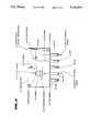
- FIG. 4is a detailed internal view of the optical transceiver of FIG. 1.
- the bi-directional optical transceiver 20is preferably incorporated into a system having electrical and optical portions where an interface is required between electrical signals and optical signals developed by the respective portions.
- the electrical portion of the systemis preferably capable of developing and receiving electrical signals
- the optical portion of the systemis preferably capable of developing and receiving optical signals.
- the bi-directional optical transceiver 20includes a lens element 21 having a molded lens 22 for receiving optical signals 56 from the optical portion of the system and a molded lens 24 for transmitting optical signals 64 to the optical portion of the system.
- the lens element 21is set into a tapered cavity 26.
- the optical transceiver 20also includes a lead frame 30 having five pins 32, 34, 36, 38 and 40 that connect with the electrical portion of the system.
- the pin 32is preferably connected to a high voltage supply, referred to as +VCC.
- the pin 34preferably provides an output electrical signal 42 to the electrical portion of the system that has been developed based on the optical signal received through the molded lens 22.
- the pins 36 and 38are preferably connected to ground.
- the pin 40preferably receives an input electrical signal 44 from the electrical portion of the system that is converted into an optical signal 64 which is output through the molded lens 24 to the optical portion of the system.
- the pin 38is connected to the collector of a transistor in the electrical portion of the system (not shown) and the pin 40 is connected to a +VCC voltage supply. Since this type of LED configuration is well known to those skilled in the art, details of its implementation are omitted for simplicity.
- the components comprising the optical transceiver 20are preferably housed in a single unit comprised of an injection molded plastic cleat 72 (FIG. 3), or some other type of packaging material. The components may also be mounted into a "TIL" pill package or other suitable container, i.e. T05, dip, etc.
- the optical transceiver 20includes an integrated circuit 50 and a photodiode 52 whose anode 53 and cathode 54 are preferably connected to connections of the integrated circuit 50 so that the photodiode 52 is reverse biased.
- the photodiode 52is preferably placed behind the molded lens 22 (FIG. 1) so that it can receive the optical signals 56 from the optical portion of the system, preferably from a fiber optic cable.
- the photodiode 52operates such that when the optical or light signal 56 from the optical portion of the system is radiated onto its P-N junction, it generates an electrical signal out of its cathode 54 that depends on the quantity of light 56 radiated. This electrical signal is provided to an input of the integrated circuit 50. It will be appreciated that other elements such as a phototransistor may be substituted in place of the photodiode 52 to receive optical signals from the optical portion of the system.
- the integrated circuit 50is preferably a transimpedance preamplifier according to the preferred embodiment. However, the use of various other types of amplifiers is also contemplated.
- the integrated circuit 50is preferably connected to each of the pins 32, 34 and 36.
- the integrated circuit 50is connected to ground through the pin 36 and receives a +VCC voltage from the pin 32.
- the integrated circuit 50produces an electrical signal 42 that is output from the pin 34 and is provided to the electrical portion of the system.
- the integrated circuit 50preferably amplifies the current from the photodiode 52 and generates a corresponding electrical signal 42 on the output pin 34. Therefore, the electrical signal 42 output on the pin 34 and provided to the electrical portion of the system varies with the magnitude of the optical or light signal 56 radiated on the photodiode 52 from the optical portion of the system.
- the bi-directional optical transceiver 20further includes a light emitting diode (LED) 60 whose anode 61 is connected to the pin 40 and whose cathode 62 is connected to the pin 38.
- the LED 60receives a current signal 44 from the electrical portion of the system through the pin 40 and generates the corresponding light or optical signal 64 that is provided to the optical portion of the system.
- the LED 60is preferably placed behind the molded lens 24 (FIG. 1) to allow the optical signal 64 generated by the LED 60 to be output through the molded lens 24.
- the optical signal 64is preferably provided to a fiber optic cable or any other type of optical signal conductor in the optical portion of the system.
- the optical transceiver 20includes a ceramic substrate 70 connected to the lead frame 30.
- the LED 60is mounted on the ceramic substrate 70.
- the integrated circuit 50 and photodiode 52are also mounted on the ceramic substrate 70.
- the ceramic substrate 70facilitates the packaging of the LED 60, the integrated circuit 50, the photodiode 52, and the lead frame 30 into a single unit.
- the molded lens 24is preferably situated normal to, centered with, and adjacent to the LED 60, and it operates to focus the light or optical signal 64 generated by the LED onto the fiber optic cable or other optical conductor (not shown) in the optical portion of the system.
- the molded lens 22is preferably similarly situated normal to, centered with, and adjacent to the photodiode 52 to focus the optical signal 56 received from the optical portion of the system onto the photodiode 52.
- the molded lenses 24 and 26are situated in a tapered cavity 26 to facilitate the generation and reception of the optical signals 64 and 56, respectively.
- the ceramic substrate 70enables the various components comprising the bi-directional optical transceiver to be mounted onto a single base.
- the anode 53 and cathode 54 of the photodiode 52include connector pads 96 and 98 that are mounted onto the ceramic substrate 70.
- the connector pads 96 and 98are connected to pads on the integrated circuit 50 through wires 100 and 102, respectively, which are routed around the ceramic substrate 70.
- the input pin 32receives the +VCC voltage supply from the system and provides this voltage through a connector pad 104 and wire 106 to a pad of the integrated circuit 50.
- the integrated circuit 50develops the output electrical signal 42 that is provided through a wire 108 to the output pin 34.
- a ground input of the integrated circuit 50is connected through a wire 114 to the pin 36, which is preferably grounded.
- the anode 61 and cathode 62 of the LED 60are connected to respective connector pads 110 and 111 mounted on the ceramic substrate 70. Bond wires 112 and 113 are provided to connect the anode 61 and cathode 62 to the respective pins 40 and 38.
- the preferred embodiment of the present inventioncomprises a bi-directional optical transceiver which is capable of performing bi-directional optical transmission.
- the transceivercomprises an LED, photodiode, and transimpedance preamplifier which are mounted onto a single base and are used for bi-directional optical and electrical communication.
- the photodiode and preamplifierare coupled together to receive optical signals and generate corresponding electrical signals, and the LED receives electrical signals and generates corresponding optical signals.
- the incorporation of an optical signal receiver and transmitter into a single unitallows for reduced size and therefore provides for more convenient operation with fiber optic cable.
Landscapes
- Physics & Mathematics (AREA)
- Electromagnetism (AREA)
- Engineering & Computer Science (AREA)
- Computer Networks & Wireless Communication (AREA)
- Signal Processing (AREA)
- Optical Couplings Of Light Guides (AREA)
Abstract
Description
Claims (6)
Priority Applications (1)
| Application Number | Priority Date | Filing Date | Title |
|---|---|---|---|
| US07/633,219US5122893A (en) | 1990-12-20 | 1990-12-20 | Bi-directional optical transceiver |
Applications Claiming Priority (1)
| Application Number | Priority Date | Filing Date | Title |
|---|---|---|---|
| US07/633,219US5122893A (en) | 1990-12-20 | 1990-12-20 | Bi-directional optical transceiver |
Publications (1)
| Publication Number | Publication Date |
|---|---|
| US5122893Atrue US5122893A (en) | 1992-06-16 |
Family
ID=24538747
Family Applications (1)
| Application Number | Title | Priority Date | Filing Date |
|---|---|---|---|
| US07/633,219Expired - LifetimeUS5122893A (en) | 1990-12-20 | 1990-12-20 | Bi-directional optical transceiver |
Country Status (1)
| Country | Link |
|---|---|
| US (1) | US5122893A (en) |
Cited By (56)
| Publication number | Priority date | Publication date | Assignee | Title |
|---|---|---|---|---|
| US5432630A (en)* | 1992-09-11 | 1995-07-11 | Motorola, Inc. | Optical bus with optical transceiver modules and method of manufacture |
| US5479288A (en)* | 1992-05-27 | 1995-12-26 | Hitachi, Ltd. | Light transmission module |
| US5526160A (en)* | 1991-05-10 | 1996-06-11 | Nec Corporation | Optical transmitter and receiver device with a single optical module |
| US5528407A (en)* | 1993-12-27 | 1996-06-18 | Rohm Co., Ltd. | Transceiver module for optical communication |
| US5528408A (en)* | 1994-10-12 | 1996-06-18 | Methode Electronics, Inc. | Small footprint optoelectronic transceiver with laser |
| US5896214A (en)* | 1996-07-01 | 1999-04-20 | Intermec Ip Corp. | Mounting bracket for mounting electronic components in a portable electronic device and method of making same |
| US5953145A (en)* | 1994-04-27 | 1999-09-14 | Thomson Consumer Electronics S.A. | Multiple light path arrangement |
| CN1048839C (en)* | 1993-09-13 | 2000-01-26 | 摩托罗拉公司 | External communication link for a credit card fager |
| USRE36820E (en) | 1995-01-13 | 2000-08-15 | Methode Electronics, Inc. | Removable optoelectronic module |
| US6154298A (en)* | 1996-04-19 | 2000-11-28 | Rohm Co., Ltd. | Optical communication device |
| US6157476A (en)* | 1996-12-21 | 2000-12-05 | Temic Telefunken Microelectronic Gmbh | Transceiver component for data transmission |
| US6179627B1 (en) | 1998-04-22 | 2001-01-30 | Stratos Lightwave, Inc. | High speed interface converter module |
| US6201704B1 (en) | 1995-01-13 | 2001-03-13 | Stratos Lightwave, Inc. | Transceive module with EMI shielding |
| US6203333B1 (en) | 1998-04-22 | 2001-03-20 | Stratos Lightwave, Inc. | High speed interface converter module |
| US6213651B1 (en) | 1999-05-26 | 2001-04-10 | E20 Communications, Inc. | Method and apparatus for vertical board construction of fiber optic transmitters, receivers and transceivers |
| US6220873B1 (en) | 1999-08-10 | 2001-04-24 | Stratos Lightwave, Inc. | Modified contact traces for interface converter |
| US6220878B1 (en) | 1995-10-04 | 2001-04-24 | Methode Electronics, Inc. | Optoelectronic module with grounding means |
| US6281999B1 (en)* | 1998-07-09 | 2001-08-28 | Zilog, Inc. | Optics system for infrared signal transceivers |
| US6301035B1 (en)* | 1997-06-28 | 2001-10-09 | Vishay Semiconductor Gmbh | Component for optical data transmission |
| US20010030789A1 (en)* | 1999-05-27 | 2001-10-18 | Wenbin Jiang | Method and apparatus for fiber optic modules |
| US20010048793A1 (en)* | 1999-05-27 | 2001-12-06 | Edwin Dair | Method and apparatus for multiboard fiber optic modules and fiber optic module arrays |
| US20020028048A1 (en)* | 1999-05-27 | 2002-03-07 | Edwin Dair | Method and apparatus for multiboard fiber optic modules and fiber optic module arrays |
| US20020030872A1 (en)* | 1999-05-27 | 2002-03-14 | Edwin Dair | Method and apparatus for multiboard fiber optic modules and fiber optic module arrays |
| US20020033979A1 (en)* | 1999-05-27 | 2002-03-21 | Edwin Dair | Method and apparatus for multiboard fiber optic modules and fiber optic module arrays |
| US6417946B1 (en)* | 1998-02-26 | 2002-07-09 | Vishay Semiconductor Gmbh | Data transmitter/receiver |
| US6477286B1 (en)* | 1999-07-16 | 2002-11-05 | Canon Kabushiki Kaisha | Integrated optoelectronic device, and integrated circuit device |
| US20030081288A1 (en)* | 1998-11-11 | 2003-05-01 | Hirohiko Ishii | Infrared communication device |
| US20030142982A1 (en)* | 2002-01-24 | 2003-07-31 | Peterson Gregory A. | Appliance control communication methods and apparatus |
| US6632030B2 (en) | 1999-05-27 | 2003-10-14 | E20 Communications, Inc. | Light bending optical block for fiber optic modules |
| US6635955B2 (en) | 2000-11-15 | 2003-10-21 | Vishay Semiconductor Gmbh | Molded electronic component |
| US20030202748A1 (en)* | 2002-04-24 | 2003-10-30 | Gordon Gary B. | Tri-state optical sytems and methods |
| US6653564B2 (en) | 2000-11-25 | 2003-11-25 | Vishay Semiconductor Gmbh | Conductor strip arrangement for a molded electronic component and process for molding |
| US6684032B1 (en)* | 1999-03-19 | 2004-01-27 | Kabushiki Kaisha Toshiba | Optical signal receiver apparatus |
| US20040069997A1 (en)* | 1999-05-27 | 2004-04-15 | Edwin Dair | Method and apparatus for multiboard fiber optic modules and fiber optic module arrays |
| US20040213516A1 (en)* | 2002-04-26 | 2004-10-28 | Gordon Gary B. | Optical transceiver systems and methods |
| US20040267947A1 (en)* | 2003-06-24 | 2004-12-30 | Sheahan Thomas J. | System and method for communicating with an appliance through an optical interface using a control panel indicator |
| US20050024012A1 (en)* | 2003-07-28 | 2005-02-03 | Jurgis Astrauskas | Method and apparatus for conserving battery for operation of a low intensity optical communication probe |
| US20050024330A1 (en)* | 2003-07-28 | 2005-02-03 | Jurgis Astrauskas | Method and apparatus for independent control of low intensity indicators used for optical communication in an appliance |
| US20050025503A1 (en)* | 2003-07-28 | 2005-02-03 | Jurgis Astrauskas | Method and apparatus for operating an optical receiver for low intensity optical communication in a high speed mode |
| US20050025493A1 (en)* | 2003-07-28 | 2005-02-03 | Jurgis Astrauskas | Method and apparatus for using a close proximity probe for optical communication with a device external to the probe |
| US6873800B1 (en) | 1999-05-26 | 2005-03-29 | Jds Uniphase Corporation | Hot pluggable optical transceiver in a small form pluggable package |
| US20050113068A1 (en)* | 2003-11-21 | 2005-05-26 | Infineon Technologies North America Corp. | Transceiver with controller for authentication |
| US6901221B1 (en) | 1999-05-27 | 2005-05-31 | Jds Uniphase Corporation | Method and apparatus for improved optical elements for vertical PCB fiber optic modules |
| US7013088B1 (en) | 1999-05-26 | 2006-03-14 | Jds Uniphase Corporation | Method and apparatus for parallel optical interconnection of fiber optic transmitters, receivers and transceivers |
| US7090509B1 (en) | 1999-06-11 | 2006-08-15 | Stratos International, Inc. | Multi-port pluggable transceiver (MPPT) with multiple LC duplex optical receptacles |
| US7116912B2 (en) | 1999-05-27 | 2006-10-03 | Jds Uniphase Corporation | Method and apparatus for pluggable fiber optic modules |
| US7181144B1 (en) | 1998-07-09 | 2007-02-20 | Zilog, Inc. | Circuit design and optics system for infrared signal transceivers |
| US7321732B2 (en) | 2003-07-28 | 2008-01-22 | Emerson Electric Co. | Method and apparatus for improving noise immunity for low intensity optical communication |
| USRE40150E1 (en) | 1994-04-25 | 2008-03-11 | Matsushita Electric Industrial Co., Ltd. | Fiber optic module |
| US20080267408A1 (en)* | 2007-04-24 | 2008-10-30 | Finisar Corporation | Protecting against counterfeit electronics devices |
| US20090100502A1 (en)* | 2007-10-15 | 2009-04-16 | Finisar Corporation | Protecting against counterfeit electronic devices |
| US20090240945A1 (en)* | 2007-11-02 | 2009-09-24 | Finisar Corporation | Anticounterfeiting means for optical communication components |
| US20100232800A1 (en)* | 2009-03-10 | 2010-09-16 | Avago Technologies Fiber Ip (Singapore) Pte. Ltd. | Parallel optical transceiver module having a heat dissipation system that dissipates heat and protects components of the module from particulates and handling |
| US8086100B2 (en) | 2001-02-05 | 2011-12-27 | Finisar Corporation | Optoelectronic transceiver with digital diagnostics |
| US8159956B2 (en) | 2008-07-01 | 2012-04-17 | Finisar Corporation | Diagnostics for serial communication busses |
| CN105122687A (en)* | 2014-03-19 | 2015-12-02 | 苹果公司 | Optical data transfer utilizing lens isolation |
Citations (12)
| Publication number | Priority date | Publication date | Assignee | Title |
|---|---|---|---|---|
| US4213394A (en)* | 1972-12-13 | 1980-07-22 | Motorola, Inc. | Spin processing active optical fuze |
| EP0053742A1 (en)* | 1980-12-06 | 1982-06-16 | Licentia Patent-Verwaltungs-GmbH | Method of transmitting signals, semiconductor device and electro-optical device for carrying out this method |
| JPS5995741A (en)* | 1982-11-25 | 1984-06-01 | Toshiba Corp | Transceiver for space propagating network |
| US4633522A (en)* | 1984-01-24 | 1986-12-30 | Sony Corporation | Apparatus for emitting and receiving light signals, more particularly infrared signals |
| US4648131A (en)* | 1983-10-07 | 1987-03-03 | Ngk Insulators, Ltd. | Work helmet having transmitter-receiver for light signal |
| JPS62265827A (en)* | 1986-05-14 | 1987-11-18 | Yagi Antenna Co Ltd | Optical transmission and reception device |
| US4717913A (en)* | 1985-08-29 | 1988-01-05 | Johnson Service Company | Data telemetry system using diffused infrared light |
| US4727600A (en)* | 1985-02-15 | 1988-02-23 | Emik Avakian | Infrared data communication system |
| JPS6416035A (en)* | 1987-07-09 | 1989-01-19 | Fujitsu Ltd | Optical signal transmitter-receiver |
| US4885804A (en)* | 1988-05-09 | 1989-12-05 | Mayle Eugene E | Optical transmitting and receiving apparatus |
| US4941205A (en)* | 1984-06-06 | 1990-07-10 | Ncr Corporation | Bidirectional optical data communications system |
| US4957348A (en)* | 1989-03-21 | 1990-09-18 | Hewlett-Packard Company | Optical transceiver with multiple communication modes |
- 1990
- 1990-12-20USUS07/633,219patent/US5122893A/ennot_activeExpired - Lifetime
Patent Citations (12)
| Publication number | Priority date | Publication date | Assignee | Title |
|---|---|---|---|---|
| US4213394A (en)* | 1972-12-13 | 1980-07-22 | Motorola, Inc. | Spin processing active optical fuze |
| EP0053742A1 (en)* | 1980-12-06 | 1982-06-16 | Licentia Patent-Verwaltungs-GmbH | Method of transmitting signals, semiconductor device and electro-optical device for carrying out this method |
| JPS5995741A (en)* | 1982-11-25 | 1984-06-01 | Toshiba Corp | Transceiver for space propagating network |
| US4648131A (en)* | 1983-10-07 | 1987-03-03 | Ngk Insulators, Ltd. | Work helmet having transmitter-receiver for light signal |
| US4633522A (en)* | 1984-01-24 | 1986-12-30 | Sony Corporation | Apparatus for emitting and receiving light signals, more particularly infrared signals |
| US4941205A (en)* | 1984-06-06 | 1990-07-10 | Ncr Corporation | Bidirectional optical data communications system |
| US4727600A (en)* | 1985-02-15 | 1988-02-23 | Emik Avakian | Infrared data communication system |
| US4717913A (en)* | 1985-08-29 | 1988-01-05 | Johnson Service Company | Data telemetry system using diffused infrared light |
| JPS62265827A (en)* | 1986-05-14 | 1987-11-18 | Yagi Antenna Co Ltd | Optical transmission and reception device |
| JPS6416035A (en)* | 1987-07-09 | 1989-01-19 | Fujitsu Ltd | Optical signal transmitter-receiver |
| US4885804A (en)* | 1988-05-09 | 1989-12-05 | Mayle Eugene E | Optical transmitting and receiving apparatus |
| US4957348A (en)* | 1989-03-21 | 1990-09-18 | Hewlett-Packard Company | Optical transceiver with multiple communication modes |
Non-Patent Citations (2)
| Title |
|---|
| Hewlett Packard, Hewlett Packard Optoelectronics Designers Catalogue 1988/89.* |
| Hewlett-Packard, Hewlett-Packard Optoelectronics Designers Catalogue 1988/89. |
Cited By (81)
| Publication number | Priority date | Publication date | Assignee | Title |
|---|---|---|---|---|
| US5526160A (en)* | 1991-05-10 | 1996-06-11 | Nec Corporation | Optical transmitter and receiver device with a single optical module |
| US5479288A (en)* | 1992-05-27 | 1995-12-26 | Hitachi, Ltd. | Light transmission module |
| US5432630A (en)* | 1992-09-11 | 1995-07-11 | Motorola, Inc. | Optical bus with optical transceiver modules and method of manufacture |
| CN1048839C (en)* | 1993-09-13 | 2000-01-26 | 摩托罗拉公司 | External communication link for a credit card fager |
| US5528407A (en)* | 1993-12-27 | 1996-06-18 | Rohm Co., Ltd. | Transceiver module for optical communication |
| USRE40154E1 (en) | 1994-04-25 | 2008-03-18 | Matsushita Electric Industrial Co., Ltd. | Fiber optic module |
| USRE40150E1 (en) | 1994-04-25 | 2008-03-11 | Matsushita Electric Industrial Co., Ltd. | Fiber optic module |
| US5953145A (en)* | 1994-04-27 | 1999-09-14 | Thomson Consumer Electronics S.A. | Multiple light path arrangement |
| US5528408A (en)* | 1994-10-12 | 1996-06-18 | Methode Electronics, Inc. | Small footprint optoelectronic transceiver with laser |
| USRE36820E (en) | 1995-01-13 | 2000-08-15 | Methode Electronics, Inc. | Removable optoelectronic module |
| US6201704B1 (en) | 1995-01-13 | 2001-03-13 | Stratos Lightwave, Inc. | Transceive module with EMI shielding |
| US6267606B1 (en) | 1995-01-13 | 2001-07-31 | Stratos Lightwave, Inc. | Removable transceiver module and receptacle |
| US6220878B1 (en) | 1995-10-04 | 2001-04-24 | Methode Electronics, Inc. | Optoelectronic module with grounding means |
| US6154298A (en)* | 1996-04-19 | 2000-11-28 | Rohm Co., Ltd. | Optical communication device |
| US5896214A (en)* | 1996-07-01 | 1999-04-20 | Intermec Ip Corp. | Mounting bracket for mounting electronic components in a portable electronic device and method of making same |
| US6157476A (en)* | 1996-12-21 | 2000-12-05 | Temic Telefunken Microelectronic Gmbh | Transceiver component for data transmission |
| US6301035B1 (en)* | 1997-06-28 | 2001-10-09 | Vishay Semiconductor Gmbh | Component for optical data transmission |
| US6417946B1 (en)* | 1998-02-26 | 2002-07-09 | Vishay Semiconductor Gmbh | Data transmitter/receiver |
| US6179627B1 (en) | 1998-04-22 | 2001-01-30 | Stratos Lightwave, Inc. | High speed interface converter module |
| US6203333B1 (en) | 1998-04-22 | 2001-03-20 | Stratos Lightwave, Inc. | High speed interface converter module |
| US6281999B1 (en)* | 1998-07-09 | 2001-08-28 | Zilog, Inc. | Optics system for infrared signal transceivers |
| US7702244B1 (en) | 1998-07-09 | 2010-04-20 | Zilog, Inc. | Circuit design and optics system for infrared signal transceivers |
| US7181144B1 (en) | 1998-07-09 | 2007-02-20 | Zilog, Inc. | Circuit design and optics system for infrared signal transceivers |
| US20030081288A1 (en)* | 1998-11-11 | 2003-05-01 | Hirohiko Ishii | Infrared communication device |
| US6684032B1 (en)* | 1999-03-19 | 2004-01-27 | Kabushiki Kaisha Toshiba | Optical signal receiver apparatus |
| US6213651B1 (en) | 1999-05-26 | 2001-04-10 | E20 Communications, Inc. | Method and apparatus for vertical board construction of fiber optic transmitters, receivers and transceivers |
| US7013088B1 (en) | 1999-05-26 | 2006-03-14 | Jds Uniphase Corporation | Method and apparatus for parallel optical interconnection of fiber optic transmitters, receivers and transceivers |
| US6873800B1 (en) | 1999-05-26 | 2005-03-29 | Jds Uniphase Corporation | Hot pluggable optical transceiver in a small form pluggable package |
| US6840686B2 (en) | 1999-05-26 | 2005-01-11 | Jds Uniphase Corporation | Method and apparatus for vertical board construction of fiber optic transmitters, receivers and transceivers |
| US20010030789A1 (en)* | 1999-05-27 | 2001-10-18 | Wenbin Jiang | Method and apparatus for fiber optic modules |
| US6632030B2 (en) | 1999-05-27 | 2003-10-14 | E20 Communications, Inc. | Light bending optical block for fiber optic modules |
| USRE41147E1 (en)* | 1999-05-27 | 2010-02-23 | Jds Uniphase Corporation | Method and apparatus for pluggable fiber optic modules |
| US20010048793A1 (en)* | 1999-05-27 | 2001-12-06 | Edwin Dair | Method and apparatus for multiboard fiber optic modules and fiber optic module arrays |
| US20020028048A1 (en)* | 1999-05-27 | 2002-03-07 | Edwin Dair | Method and apparatus for multiboard fiber optic modules and fiber optic module arrays |
| US20040069997A1 (en)* | 1999-05-27 | 2004-04-15 | Edwin Dair | Method and apparatus for multiboard fiber optic modules and fiber optic module arrays |
| US20020030872A1 (en)* | 1999-05-27 | 2002-03-14 | Edwin Dair | Method and apparatus for multiboard fiber optic modules and fiber optic module arrays |
| US7116912B2 (en) | 1999-05-27 | 2006-10-03 | Jds Uniphase Corporation | Method and apparatus for pluggable fiber optic modules |
| US20020033979A1 (en)* | 1999-05-27 | 2002-03-21 | Edwin Dair | Method and apparatus for multiboard fiber optic modules and fiber optic module arrays |
| US6952532B2 (en) | 1999-05-27 | 2005-10-04 | Jds Uniphase Corporation | Method and apparatus for multiboard fiber optic modules and fiber optic module arrays |
| US6901221B1 (en) | 1999-05-27 | 2005-05-31 | Jds Uniphase Corporation | Method and apparatus for improved optical elements for vertical PCB fiber optic modules |
| US7090509B1 (en) | 1999-06-11 | 2006-08-15 | Stratos International, Inc. | Multi-port pluggable transceiver (MPPT) with multiple LC duplex optical receptacles |
| US6477286B1 (en)* | 1999-07-16 | 2002-11-05 | Canon Kabushiki Kaisha | Integrated optoelectronic device, and integrated circuit device |
| US6220873B1 (en) | 1999-08-10 | 2001-04-24 | Stratos Lightwave, Inc. | Modified contact traces for interface converter |
| US6635955B2 (en) | 2000-11-15 | 2003-10-21 | Vishay Semiconductor Gmbh | Molded electronic component |
| US6653564B2 (en) | 2000-11-25 | 2003-11-25 | Vishay Semiconductor Gmbh | Conductor strip arrangement for a molded electronic component and process for molding |
| US10291324B2 (en) | 2001-02-05 | 2019-05-14 | Finisar Corporation | Method of monitoring an optoelectronic transceiver with multiple flag values for a respective operating condition |
| US9577759B2 (en) | 2001-02-05 | 2017-02-21 | Finisar Corporation | Method of monitoring an optoelectronic transceiver with multiple flag values for a respective operating condition |
| US9184850B2 (en) | 2001-02-05 | 2015-11-10 | Finisar Corporation | Method of monitoring an optoelectronic transceiver with multiple flag values for a respective operating condition |
| US8849123B2 (en) | 2001-02-05 | 2014-09-30 | Finisar Corporation | Method of monitoring an optoelectronic transceiver with multiple flag values for a respective operating condition |
| US8515284B2 (en) | 2001-02-05 | 2013-08-20 | Finisar Corporation | Optoelectronic transceiver with multiple flag values for a respective operating condition |
| US8086100B2 (en) | 2001-02-05 | 2011-12-27 | Finisar Corporation | Optoelectronic transceiver with digital diagnostics |
| US20030142982A1 (en)* | 2002-01-24 | 2003-07-31 | Peterson Gregory A. | Appliance control communication methods and apparatus |
| US20030170033A1 (en)* | 2002-01-24 | 2003-09-11 | Peterson Gregory A. | System and method for communicating with an appliance through a light emitting diode |
| US6919815B2 (en) | 2002-01-24 | 2005-07-19 | Emerson Electric Co. | Appliance control communication methods and apparatus |
| US7030773B2 (en) | 2002-01-24 | 2006-04-18 | Emerson Electric Company | System and method for communicating with an appliance through a light emitting diode |
| US6956996B2 (en) | 2002-04-24 | 2005-10-18 | Agilent Technologies, Inc. | Tri-state optical systems and methods |
| US20030202748A1 (en)* | 2002-04-24 | 2003-10-30 | Gordon Gary B. | Tri-state optical sytems and methods |
| US7184669B2 (en) | 2002-04-26 | 2007-02-27 | Avago Technologies Fiber Ip (Singapore) Pte. Ltd. | Optical transceiver systems and methods |
| US20040213516A1 (en)* | 2002-04-26 | 2004-10-28 | Gordon Gary B. | Optical transceiver systems and methods |
| US7243174B2 (en) | 2003-06-24 | 2007-07-10 | Emerson Electric Co. | System and method for communicating with an appliance through an optical interface using a control panel indicator |
| US20040267947A1 (en)* | 2003-06-24 | 2004-12-30 | Sheahan Thomas J. | System and method for communicating with an appliance through an optical interface using a control panel indicator |
| US7321732B2 (en) | 2003-07-28 | 2008-01-22 | Emerson Electric Co. | Method and apparatus for improving noise immunity for low intensity optical communication |
| US7091932B2 (en) | 2003-07-28 | 2006-08-15 | Emerson Electric Co. | Method and apparatus for independent control of low intensity indicators used for optical communication in an appliance |
| US20050025493A1 (en)* | 2003-07-28 | 2005-02-03 | Jurgis Astrauskas | Method and apparatus for using a close proximity probe for optical communication with a device external to the probe |
| US20050025503A1 (en)* | 2003-07-28 | 2005-02-03 | Jurgis Astrauskas | Method and apparatus for operating an optical receiver for low intensity optical communication in a high speed mode |
| US7315148B2 (en) | 2003-07-28 | 2008-01-01 | Emerson Electric Co. | Method and apparatus for conserving battery for operation of a low intensity optical communication probe |
| US7280769B2 (en) | 2003-07-28 | 2007-10-09 | Emerson Electric Co. | Method and apparatus for operating an optical receiver for low intensity optical communication in a high speed mode |
| US20050024012A1 (en)* | 2003-07-28 | 2005-02-03 | Jurgis Astrauskas | Method and apparatus for conserving battery for operation of a low intensity optical communication probe |
| US20050024330A1 (en)* | 2003-07-28 | 2005-02-03 | Jurgis Astrauskas | Method and apparatus for independent control of low intensity indicators used for optical communication in an appliance |
| US20050113068A1 (en)* | 2003-11-21 | 2005-05-26 | Infineon Technologies North America Corp. | Transceiver with controller for authentication |
| US8165297B2 (en) | 2003-11-21 | 2012-04-24 | Finisar Corporation | Transceiver with controller for authentication |
| US20080267408A1 (en)* | 2007-04-24 | 2008-10-30 | Finisar Corporation | Protecting against counterfeit electronics devices |
| US8762714B2 (en) | 2007-04-24 | 2014-06-24 | Finisar Corporation | Protecting against counterfeit electronics devices |
| US9148286B2 (en)* | 2007-10-15 | 2015-09-29 | Finisar Corporation | Protecting against counterfeit electronic devices |
| US20090100502A1 (en)* | 2007-10-15 | 2009-04-16 | Finisar Corporation | Protecting against counterfeit electronic devices |
| US20090240945A1 (en)* | 2007-11-02 | 2009-09-24 | Finisar Corporation | Anticounterfeiting means for optical communication components |
| US8406142B2 (en) | 2008-07-01 | 2013-03-26 | Finisar Corporation | Diagnostics for a serial communications device |
| US8159956B2 (en) | 2008-07-01 | 2012-04-17 | Finisar Corporation | Diagnostics for serial communication busses |
| US8351794B2 (en)* | 2009-03-10 | 2013-01-08 | Avago Technologies Fiber Ip (Singapore) Pte. Ltd. | Parallel optical transceiver module having a heat dissipation system that dissipates heat and protects components of the module from particulates and handling |
| US20100232800A1 (en)* | 2009-03-10 | 2010-09-16 | Avago Technologies Fiber Ip (Singapore) Pte. Ltd. | Parallel optical transceiver module having a heat dissipation system that dissipates heat and protects components of the module from particulates and handling |
| CN105122687A (en)* | 2014-03-19 | 2015-12-02 | 苹果公司 | Optical data transfer utilizing lens isolation |
Similar Documents
| Publication | Publication Date | Title |
|---|---|---|
| US5122893A (en) | Bi-directional optical transceiver | |
| US6203212B1 (en) | Optical subassembly for use in fiber optic data transmission and reception | |
| US7101089B2 (en) | Jack module for optical transmission and plug-and-jack type optical transmission apparatus | |
| US7418208B2 (en) | Optoelectronic transceiver for a bidirectional optical signal transmission | |
| US5493437A (en) | External communication link for a credit card pager | |
| US6364542B1 (en) | Device and method for providing a true semiconductor die to external fiber optic cable connection | |
| US4268113A (en) | Signal coupling element for substrate-mounted optical transducers | |
| US5432630A (en) | Optical bus with optical transceiver modules and method of manufacture | |
| US4307934A (en) | Packaged fiber optic modules | |
| US9470864B1 (en) | Photoelectric conversion module | |
| US5101465A (en) | Leadframe-based optical assembly | |
| US20090269006A1 (en) | Optical module and method of manufacturing thereof | |
| JPS58111008A (en) | Optical module | |
| JPH07183851A (en) | Smart optical connector and smart optical connector system | |
| KR20000025095A (en) | Optical connector module | |
| US6900512B2 (en) | Light-receiving module | |
| EP0508613B1 (en) | Multichip system and method of supplying clock signal therefor | |
| US8303194B2 (en) | Transceiver and bi-directional signal transmission system thereof | |
| JP2003004987A (en) | Optical transmission and reception module installation structure | |
| JP2989845B2 (en) | Optical signal repeater | |
| US6430326B1 (en) | Module for parallel optical data transmission | |
| CN111650703B (en) | QSFP single-fiber bidirectional optical coupling assembly and optical module | |
| KR19990008284A (en) | Electrical plug device | |
| CN218352506U (en) | Light receiving device and optical module | |
| JPS6259478B2 (en) |
Legal Events
| Date | Code | Title | Description |
|---|---|---|---|
| AS | Assignment | Owner name:COMPAQ COMPUTER CORPORATION, A CORP. OF DELAWARE Free format text:ASSIGNMENT OF ASSIGNORS INTEREST.;ASSIGNOR:TOLBERT, CLOYS G.;REEL/FRAME:005558/0771 Effective date:19901217 | |
| STCF | Information on status: patent grant | Free format text:PATENTED CASE | |
| FPAY | Fee payment | Year of fee payment:4 | |
| FEPP | Fee payment procedure | Free format text:PAYOR NUMBER ASSIGNED (ORIGINAL EVENT CODE: ASPN); ENTITY STATUS OF PATENT OWNER: LARGE ENTITY | |
| FPAY | Fee payment | Year of fee payment:8 | |
| AS | Assignment | Owner name:COMPAQ INFORMATION TECHNOLOGIES GROUP, L.P., TEXAS Free format text:ASSIGNMENT OF ASSIGNORS INTEREST;ASSIGNOR:COMPAQ COMPUTER CORPORATION;REEL/FRAME:012418/0222 Effective date:20010620 | |
| FPAY | Fee payment | Year of fee payment:12 | |
| AS | Assignment | Owner name:HEWLETT-PACKARD DEVELOPMENT COMPANY, L.P., TEXAS Free format text:CHANGE OF NAME;ASSIGNOR:COMPAQ INFORMATION TECHNOLOGIES GROUP, LP;REEL/FRAME:015000/0305 Effective date:20021001 |