US5122796A - Object detection method and apparatus emplying electro-optics - Google Patents
Object detection method and apparatus emplying electro-opticsDownload PDFInfo
- Publication number
- US5122796A US5122796AUS07/763,471US76347191AUS5122796AUS 5122796 AUS5122796 AUS 5122796AUS 76347191 AUS76347191 AUS 76347191AUS 5122796 AUS5122796 AUS 5122796A
- Authority
- US
- United States
- Prior art keywords
- zone
- detector
- emitter
- signal
- energy
- Prior art date
- Legal status (The legal status is an assumption and is not a legal conclusion. Google has not performed a legal analysis and makes no representation as to the accuracy of the status listed.)
- Expired - Fee Related
Links
- 238000001514detection methodMethods0.000titleclaimsdescription39
- 238000001228spectrumMethods0.000claimsdescription14
- 230000003213activating effectEffects0.000claimsdescription12
- 238000000034methodMethods0.000claimsdescription8
- 238000009825accumulationMethods0.000abstractdescription3
- 230000001360synchronised effectEffects0.000description27
- 230000006870functionEffects0.000description12
- 238000010586diagramMethods0.000description10
- 230000003287optical effectEffects0.000description9
- 230000003111delayed effectEffects0.000description8
- 239000003990capacitorSubstances0.000description6
- 230000004044responseEffects0.000description6
- 230000004048modificationEffects0.000description5
- 238000012986modificationMethods0.000description5
- 230000000007visual effectEffects0.000description5
- 230000010363phase shiftEffects0.000description3
- 230000035508accumulationEffects0.000description2
- 230000004913activationEffects0.000description2
- 230000005540biological transmissionEffects0.000description2
- 230000003247decreasing effectEffects0.000description2
- 238000013461designMethods0.000description2
- 239000006185dispersionSubstances0.000description2
- 230000006872improvementEffects0.000description2
- 239000000463materialSubstances0.000description2
- 238000012544monitoring processMethods0.000description2
- 230000001105regulatory effectEffects0.000description2
- 239000004065semiconductorSubstances0.000description2
- 230000035945sensitivityEffects0.000description2
- XUIMIQQOPSSXEZ-UHFFFAOYSA-NSiliconChemical compound[Si]XUIMIQQOPSSXEZ-UHFFFAOYSA-N0.000description1
- 238000007792additionMethods0.000description1
- 230000004888barrier functionEffects0.000description1
- 230000008859changeEffects0.000description1
- 238000004891communicationMethods0.000description1
- 230000000295complement effectEffects0.000description1
- 238000005094computer simulationMethods0.000description1
- 230000000694effectsEffects0.000description1
- 238000005516engineering processMethods0.000description1
- 230000002452interceptive effectEffects0.000description1
- 238000002955isolationMethods0.000description1
- 238000004519manufacturing processMethods0.000description1
- QSHDDOUJBYECFT-UHFFFAOYSA-NmercuryChemical compound[Hg]QSHDDOUJBYECFT-UHFFFAOYSA-N0.000description1
- 239000013618particulate matterSubstances0.000description1
- 230000008569processEffects0.000description1
- 230000005855radiationEffects0.000description1
- 229910052710siliconInorganic materials0.000description1
- 239000010703siliconSubstances0.000description1
Images


Classifications
- G—PHYSICS
- G01—MEASURING; TESTING
- G01S—RADIO DIRECTION-FINDING; RADIO NAVIGATION; DETERMINING DISTANCE OR VELOCITY BY USE OF RADIO WAVES; LOCATING OR PRESENCE-DETECTING BY USE OF THE REFLECTION OR RERADIATION OF RADIO WAVES; ANALOGOUS ARRANGEMENTS USING OTHER WAVES
- G01S17/00—Systems using the reflection or reradiation of electromagnetic waves other than radio waves, e.g. lidar systems
- G01S17/88—Lidar systems specially adapted for specific applications
- G01S17/93—Lidar systems specially adapted for specific applications for anti-collision purposes
- G01S17/931—Lidar systems specially adapted for specific applications for anti-collision purposes of land vehicles
- G—PHYSICS
- G01—MEASURING; TESTING
- G01S—RADIO DIRECTION-FINDING; RADIO NAVIGATION; DETERMINING DISTANCE OR VELOCITY BY USE OF RADIO WAVES; LOCATING OR PRESENCE-DETECTING BY USE OF THE REFLECTION OR RERADIATION OF RADIO WAVES; ANALOGOUS ARRANGEMENTS USING OTHER WAVES
- G01S7/00—Details of systems according to groups G01S13/00, G01S15/00, G01S17/00
- G01S7/48—Details of systems according to groups G01S13/00, G01S15/00, G01S17/00 of systems according to group G01S17/00
- G01S7/481—Constructional features, e.g. arrangements of optical elements
- G01S7/4811—Constructional features, e.g. arrangements of optical elements common to transmitter and receiver
- G—PHYSICS
- G01—MEASURING; TESTING
- G01S—RADIO DIRECTION-FINDING; RADIO NAVIGATION; DETERMINING DISTANCE OR VELOCITY BY USE OF RADIO WAVES; LOCATING OR PRESENCE-DETECTING BY USE OF THE REFLECTION OR RERADIATION OF RADIO WAVES; ANALOGOUS ARRANGEMENTS USING OTHER WAVES
- G01S7/00—Details of systems according to groups G01S13/00, G01S15/00, G01S17/00
- G01S7/48—Details of systems according to groups G01S13/00, G01S15/00, G01S17/00 of systems according to group G01S17/00
- G01S7/497—Means for monitoring or calibrating
- G01S2007/4975—Means for monitoring or calibrating of sensor obstruction by, e.g. dirt- or ice-coating, e.g. by reflection measurement on front-screen
Definitions
- the present inventionbroadly relates to systems for detecting the presence of an object within an area or areas under surveillance, and deals more particularly with a detection system which employs electro-optics to sense the presence of the object, and is particularly well-suited for use by vehicles to avoid collisions.
- ultrasonic-type systemsare rather slow in terms of response time and are particularly subject to various kinds of interference due to wind buffeting and eddies as well as other sources of interfering noise which reduces the reliability of the systems.
- the ultrasonic transducer employed in these systemsmust be mounted in the open air, thus subjecting it to airborne dirt and moisture which can eventually interfere with the proper operation of the system.
- Optical systemsare also known which measure the time of flight for light transmitted from the vehicle, to the object and back.
- these systemsalso require expensive components and relatively complex circuitry.
- apparatusfor detecting the presence of an object within an area under surveillance which employs an electro-optical emitter and receiver which are relatively simple in design and inexpensive to manufacture, but yet which are highly effective and not subject to reliability problems due to interference.
- the emitteremits light energy which is modulated with a preselected frequency spectrum to provide the emitted light energy with a characteristic signature.
- Light within the area under surveillanceis received by a receiver which is mounted adjacent the emitter.
- the receiverincludes a filter for passing only a portion of the received light energy from the object which possesses a band of preselected wavelengths.
- a photosensitive semiconductor deviceconverts the filtered light into an electrical signal which varies in accordance with the magnitude of filtered light.
- This electrical signalis amplified by a band-pass amplifier which amplifies selected frequencies in the signal and the amplified signal is then synchronously detected in accordance with the modulation frequency spectrum to determine the magnitude of filtered light which possesses the characteristic signature that is reflected from the object.
- the synchronously derived signalis compared with a threshold value to determine whether an object is present within the area under surveillance. The presence of an object or another vehicle within the area of surveillance is announced to the driver by way of an audible and/or visual signal.
- the preselected frequency spectrumis keyed in a manner which will prevent interference between similar systems on other nearby vehicles.
- the frequency spectrumpreferably varies over time in a unique fashion and can also contain a plurality of component frequencies. Synchronous detection insures that the apparatus only responds to a signal having the unique modulation key.
- the electrical signalis, in addition, synchronously detected at a 90° phase delay.
- the result of phase delayed detectionis an indication of either interference from other systems or of a distance to the object being greater than the area of interest due to its long time-of-flight.
- the locations of objects in several zonesare detected by employing emitters with annularly separated beams.
- Each beamis given some unique characteristic to allow a detector to distinguish among the beams.
- the emitted beamsmay be given unique modulation frequency spectra or alternatively may be emitted in a time multiplexed sequence.
- the number of zonescan be increased by employing a plurality of detectors each monitoring a different zone.
- FIG. 1is a plan view of a host vehicle having the object detection apparatus of the present invention installed thereon and shown on a three lane road in which the host vehicle is passing cars in an adjacent lane;
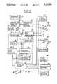
- FIG. 2is a broad block diagram of the object detection apparatus which forms the preferred embodiment of the present invention.
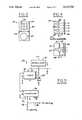
- FIG. 3is an elevational view of the front of a detector unit which includes the emitter and receiver portions of the detection apparatus;
- FIG. 4is a diagrammatic view showing the relationship between the emitter and receiver portions of the unit shown in FIG. 3;
- FIG. 5is a detailed schematic diagram of the controller shown in FIG. 2;
- FIG. 6is a detailed schematic diagram showing one of the modulator source drivers and one set of corresponding emitters depicted in FIG. 2;
- FIG. 7is a combined block and detailed schematic diagram of the receiver portion shown in FIG. 2;
- FIG. 8is a detailed schematic diagram of the band-pass amplifier shown in FIG. 2;
- FIG. 9is a combined block and detailed schematic diagram depicting the synchronous detector and threshold comparators shown in FIG. 2;
- FIG. 10is a block diagram of an alternate embodiment of the object detection apparatus of the invention.
- FIG. 11is a schematic diagram showing a modification to the controller of FIG. 5;
- FIG. 12is a schematic diagram showing a modification to the synchronous detector circuit of FIG. 9.
- FIG. 13is a diagram showing zonal detection in a further embodiment of the present invention.
- the present inventionbroadly relates to apparatus for detecting the presence of an object within an area under surveillance which employs an electro-optical system for detecting the presence of the object.
- the detection apparatus of the present inventionmay be used advantageously in a variety of applications such as security monitoring, collision avoidance systems, etc. For illustrative purposes, however, the detection apparatus of the present invention will be described in detail in connection with a collision avoidance system for vehicles.
- the object detection apparatus of the present inventionmay be installed on a host vehicle 10 for the purpose of alerting the vehicle's driver of the presence of an object, such as an adjacent car, within an area under surveillance.
- the object detection apparatusincludes a detection unit 18 mounted on each rear corner of the vehicle 10, in or near the tail lights thereof.
- the detection units 18may be mounted on the vehicle's license plate bracket or inside the vehicle 10, in front of the rear window thereof.
- Each of the detection units 18emits a fan-shaped beam 12 of light energy in the infrared region, and preferably at a wavelength of approximately 850 to 980 nanometers.
- the beam 12diverges at approximately a 25 degree angle and has its center line 14 positioned approximately 45 degrees from an axis 16 which extends parallel to the vehicle's path of travel and through the corresponding detection unit.
- the effective area under surveillance by the detection units 18is indicated within the broken line 15. It may thus be appreciated from FIG. 1 that the area 15 under surveillance constitutes a potential "blind spot" which the driver has difficulty viewing, either by use of rear view mirrors or by turning his head.
- the use of the object detection apparatus of the present invention as a detector for vehicles that monitors a zone of potential contactis particularly well-suited to assist the driver in changing lanes while traveling in multiple lane traffic.
- the apparatusis designed to alert the driver of the host vehicle 10 by means of a visual and/or audible signal when another car enters the area 15 under surveillance which may be considered a "zone of potential contact".
- a visual and/or audible signalwhen another car enters the area 15 under surveillance which may be considered a "zone of potential contact".
- both an audible and a visual alarmare provided in the passenger compartment to alert the driver of the presence of an object within the monitored areas.
- the volume of the audible alarmis preferably adjustable by the driver. In a first mode of operation, both the audible and visual alarms are activated when an object is detected within the monitored area, although the driver may disable the audible alarm by fully decreasing its volume.
- the audible alarmis activated at full volume regardless of the volume setting level, and the visual alarm is also activated when an object is detected; in this manner, the driver is provided with an alarm to ensure that he or she does not change lanes until cars in the adjacent lane into which the driver is turning are at a safe passing distance.
- the object detector of the present inventionalerts the driver of the host vehicle 10 when an adjacent vehicle passes or is in the process of passing the host vehicle 10.
- FIG. 2depicts the basic components of the object detection apparatus described above with reference to FIG. 1.
- a detection unit 18is mounted on each rear corner of the vehicle 10 and is positioned so as to monitor an area several degrees on each side of a center line extending roughly 45 degrees from the path of travel of the vehicle 10, as discussed in FIG. 1 above.
- each of the units 18includes an emitter portion 20 and a receiver portion 22 preferably mounted in a common, light tight housing 54 and separated by a barrier 66 of suitable opaque material which prevents optical communication between the emitter portion 20 and receiver portion 22.
- the emitter portion 20 and receiver portion 22are covered by an outer shield 56 of material which is transparent to the wavelength of light of interest.
- the shield 56may comprise two component parts, as shown in FIG. 4, or may be a single unit which covers the entire face of the housing 54.
- the emitter portion 20comprises a plurality of electro-optical infrared emitters 58 which will be discussed later in more detail.
- the emitters 58are preferably arranged in an array which, in FIG. 3, is shown as three rows of three columns.
- the receiver portion 22 of the detector unit 18includes a photosensitive semiconductor element 60 such as PIN photodiode which will be discussed later in more detail.
- the photosensitive device 60is sensitive to light energy within a preselected band of wavelengths, for example, between 750 and 1100 nanometers, and functions to convert the received light energy impinging thereon into an electrical signal which varies in accordance with the magnitude of received light energy.
- Light passing through the shield 56 and a filter 64are focused on the photoresponsive element 60 by means of an aspherical optical lens 62.
- the filter 64may comprise a conventional optical filter which substantially attenuates light energy outside a preselected wavelength.
- the filter 64may be selected to provide a peak response at a wavelength corresponding to that of the light energy emitted by emitters 58.
- meansare provided to detect the presence of an accumulation of foreign matter on the exterior of the shields 56.
- This foreign mattermay consist of moisture, ice or other particulate matter which adhere to the face of the shield 56 and reduces the amount of light energy picked up by the receiver portion 22.
- This additional detection meansis in the form of an optical pick-up 68 which is mounted within the housing 54 and is oriented so as to optically sense the presence of accumulations on the shields 56. The optical pick-up 68 will be discussed later in more detail.
- the emitter portions 20 of the detection unitsare driven by a controller 26 and modulator source drivers 28.
- the controller 26functions as a master clock which produces a clock signal at a preselected frequency. It has been found that a frequency of at least between 50 and 60 KHz, and preferably 56 KHz provides optimum results.
- This clock signalis used to modulate the source drivers 28 which in turn drive the emitter portions 20.
- the light energy at the preselected wavelength emanating from the emitters 58is therefore modulated at the preselected clock frequency of the controller 26. Modulation at this particular frequency substantially reduces the possibility of interference in the system due to quick flashes of light that may be received by the receiver portion 22 which may be picked up from background sunlight and shadows.
- the preselected modulation frequencyalso acts as a signature which is keyed into the emitted light energy which can later be recognized and processed by the receiver portion.
- a conventional optical filter 64functions to attenuate light energy outside a particular, preselected wavelength or range of wavelengths.
- the filtered light energyis converted to an electrical signal which is delivered on lines 100 to a band-pass amplifier 30.
- the band-pass amplifier 30is tuned to the frequency of the controller 26 and functions to amplify signals having a frequency within a preselected range of the clock frequency provided by the controller 26.
- the band-pass amplifier 30functions as a first level discriminator to select from the complex waveform input signal those signal components having the characteristic signature frequency of the controller 26.
- the outputs of the band-pass amplifier 30are delivered on lines 122 to a synchronous detector 32.
- the synchronous detector 32receives a timing reference signal 78 from the controller 26 which is identical to that delivered on line 82 to the modulator source drivers 28.
- the synchronous detector 32functions to sample the amplified signal received on lines 122 at the rate or frequency of the clock signal on line 78.
- the synchronous detector 32thus forms a second level discriminator which more precisely excises that portion of the received complex waveform signal which includes the signature frequency of the controller 26.
- the outputs of the synchronous detector 32are a pair of signals whose magnitude is proportional to the quantity of reflected light energy respectively received by the receiver portions 22 and which originated from the corresponding emitter portions 20. These output signals are delivered to a pair of threshold comparators 34 which compare the magnitude of the input signals with corresponding threshold values which may be adjusted by means of threshold pots 36. In the event that the magnitude of either of the signals applied by the synchronous detector 32 exceed the threshold values, a corresponding alarm signal is delivered on either or both of the lines 136 to display logic 38. Display logic 38 is responsive to these latter-mentioned signals to enable one or more lights 40 and/or an audio device 42, thereby to alert the driver that an object 24 has been detected.
- the threshold pots 36effectively provide a means for adjusting the sensitivity of the detection system, and thus the range or distance that the detection units 18 are effective to detect the object 24.
- An optional overload detector 52may be provided to sense the condition in which either of the amplified signals produced by the amplifier 30 exceed a preselected value which indicates that the receiving portions 22 are temporarily "blinded" by an overload condition (e.g. intense sunlight). In the event of such an overload condition, the overload detector 52 delivers a signal to the display logic 38 which results in the activation of an additional alarm annunciator (not shown) dedicated to announcing such overload.
- an overload conditione.g. intense sunlight
- Additional detection units 18may be provided at different positions on the vehicle 10 in order to sense the rate at which an adjacent vehicle is being passed.
- multiple sets of detection units 18wherein at least two contiguous or overlapping beams are provided on each side of the vehicle, it is possible to create patterns of reflected signals which may be deciphered by an optional closing rate detector 50 to determine whether the host vehicle 10 is getting closer or farther away from an adjacent vehicle or object.
- the closing rate detector 50can employ complex algorithms which can determine whether an adjacent vehicle is closing on the host vehicle in a longitudinal direction (parallel to the host vehicle) or in a radial or azimuthal direction (changing lanes).
- the closing rate detector 50is driven by an output of the synchronous detector 32 and functions either through hardware or software to detect a steady increase in the incoming reflection signal.
- the closing rate detector 50may function as a second threshold detector which compares the signal from the synchronous detector and activates a suitable alarm (not shown) through the display logic 38 when the detected object has "closed" to a preselected distance from the host vehicle 10.
- FIG. 5depicts the details of the controller 26.
- the controller 26functions to produce a modulating clock signal which turns the emitters 58 on and off at a preselected frequency. Based on computer modeling, a frequency of 56 KHz has been found to be a sufficiently high frequency to provide optimum discrimination against background sunlight and light from other sources.
- the controller 26may be implemented either through software or by hardware as shown in FIG. 5 to generate the 56 KHz square wave, preferably with a stability of less than or equal to ⁇ 0.2%.
- the controller 26includes a timer chip 74 such as an LM555CN microcircuit which is driven by a suitable source of voltage regulated by a voltage regulator 72.
- the exact frequency of the timer 74may be adjusted using a potentiometer 80.
- a 112 KHz clock signalis output to a flip-flop 76 which acts as a divider to generate 50 percent duty cycle complementary clock signals which are output as a 56 KHz digital square wave on lines 78 and 82 respectively to the synchronous detector 32 and modulator source drivers 28 (FIG. 2).
- the details of one of the modulator source drivers 28 and a corresponding set of emitters 58is shown in FIG. 6.
- the 56 KHz signal received on line 82is inverted by an inverter 84 and is used to drive the base of an NPN power transistor 86, which in turn controls an NPN power transistor 88.
- the output of each of the drivers 28is delivered as a modulating current signal to a corresponding set of three series connected emitters 58 which form a portion of the emitter unit 20.
- the emitters 58may comprise, for example, Siemens LD273 light emitting diodes which are positioned closely together and have a nominal 100 mA peak driver current. The rated emission in the center of the output beam 12 (FIG.
- the emitter portion 20is 270 mW-steradian at a wavelength of 950 nanometers.
- the resulting beam 12has a nominal 15 degree vertical dispersion and 25 degree horizontal dispersion.
- Rated switching time for emitters 58is approximately one microsecond and actual on and off times are each approximately 9 microseconds.
- the emitters 58are arranged in a three-by-three array, with each side of the array extending approximately one-half inch.
- the array of emitters 58may be separated from the receiver portion 22 (FIG. 3) by approximately four inches.
- the five remaining drivers 28 and sets of emitters 58are identical in detail to the single circuit shown in FIG. 6.
- the receiver portion 22includes a silicon PIN photodiode 23 which may comprise a Siemens SFH205 device onto which received light energy is focused by the previously mentioned aspheric optical lens 62 (FIG. 4).
- the previously mentioned filter 64may be defined by an infrared transmitting plastic which encases the photodiode 23 and functions to block radiation below 800 nanometers wavelength and provides a peak response at 950 nanometers. The filter 64 functions to effectively reject the flickering light from mercury vapor street lights, etc. and reduces the photodiode's sensitivity to sunlight.
- the output of the photodiode 23is delivered to the inverting input of an op-amp 90 which functions as a pre-amplifier. Power is supplied to the operational amplifier 90 by a DC/DC converter 96 and decoupling of electrical noise on the input power line is accomplished through a regulator 98.
- the output of the op-amp 90is a DC-coupled signal having an approximately 150 KHz high frequency cut-off and is proportional in magnitude to the quantity of light energy received by the photodiode 23.
- An inductor used in combination with a resistor and a capacitor in the feedback circuit of amplifier 90can be used to selectively amplify the desired frequency band and reduce the effect of sunlight.
- the output signal from op-amp 90is delivered on line 100 to the input of a corresponding band-pass amplifier 30, the details of one of which are depicted in FIG. 8.
- the input signal on line 100is coupled via capacitor 102 to the non-inverting input of an op-amp 104 and to an LC network 106 consisting of a capacitor 110 in parallel with an adjustable band-pass coil 108.
- the output of the op-amp 104is coupled via capacitor 105 to the non-inverting input of a second op-amp 120 as well as to a second LC network 112 consisting of a capacitor 116 in parallel with an adjustable band-pass coil 114.
- Regulated power to the amplifieris provided through a voltage regulator 118.
- the LC networks 106 and 112in combination with op-amps 104 and 120, form two tuned stages, each used as a detector and each having a bandwidth of ⁇ approximately 1 KHz for each stage with zero phase shift at the center frequency.
- the total peak gain provided by both stagesis approximately 2000 at 56 KHz with a 3 db bandwidth of 500 Hz.
- FIG. 9wherein the details of the synchronous detector 32 are depicted.
- the inputs from the band-pass amplifiers 30 associated with detection units 18are coupled by capacitors 124 to the inputs of an analog multiplexer which may comprise, for example, a CD4052A microcircuit.
- Pin 10 of the multiplexer 126receives the 56 KHz timing reference via line 78.
- the multiplexer 126is driven by the timing reference signal to operate as a phase detector which operates to isolate the incoming signals on line 122 that result from light reflected from the object 24 which originates from the emitters 58.
- This signalis amplified and averaged by amplifier 128 to give a DC signal having a response time of 0.05 seconds and is respectively delivered to a pair of corresponding, identical comparator circuits 34, one of the comparator circuits 34 being shown in detail, the other being depicted in a block form.
- the inputs to the multiplexer 126 on lines 122are respectively switched between two sets of output lines which are connected to the inverting and non-inverting input terminals of an operational amplifier 130. This switching is performed at the 56 KHz rate of the controller 26. Since the non-inverting input of op-amp 130 is connected to circuit common, the output of op-amp 130 is a measure of detected light in synchronism with the emitted light. In the event that the incoming signal does not correspond to the modulation frequency spectrum (e.g. background radiant with a wide frequency spectrum), then the average value summed by the op-amp 130 is zero.
- the modulation frequency spectrume.g. background radiant with a wide frequency spectrum
- op-amp 130provides an output to the inverting input of the threshold comparator 34.
- the threshold comparator 34compares the value on its inverting input with a value on its non-inverting input established by a potentiometer 134. If the threshold value is exceeded, a signal is output on the corresponding line 136 to the display logic 38, thereby resulting in the activation of one or more alarms.
- the display logic 38may receive activating signals from a turn signal sensor 44, an accelerator sensor 46, or a steering sensor 48 which are employed to selectively enable the alarm outputs 40, 42.
- a turn signal sensor 44an accelerator sensor 46, or a steering sensor 48 which are employed to selectively enable the alarm outputs 40, 42.
- any of these latter-mentioned input signalscan be used as an indication that the host vehicle 10 is commencing a passing maneuver, in which case the audio alarm 42, for example, is activated as long as the presence of an object 24 is detected within the area under surveillance.
- the previously discussed dirty window detector 68may comprise a system identical to the primary detection system previously described, but with decreased gain and a higher detection threshold.
- a keyed modulation techniquemay be employed.
- the controller 26would employ any suitable means (such as computer software) to vary the frequency of modulation of the emitted light energy.
- the modulation frequencywould be varied in accordance with a "key" unique to each vehicle and would appear to be “random" to the receivers of other vehicles.
- the receiver of each vehicle equipped with the detection systemwould include a correlation detector capable of detecting only the reflected signal having the keyed modulation frequency which is unique to that vehicle.
- FIG. 10shows an alternate embodiment of the present invention which includes a modification to the circuit of FIG. 2 for achieving this keyed modulation technique.
- a sequence generator 140is connected to controller 26 for providing a sequence of modulating frequencies which provide a characteristic "key" for a particular unit.
- Controller 26is modified to provide variable frequency clock signals under the control of sequence generator 140.
- the activating signal provided on lines 82 and 78has a frequency spectrum which can either contain one component frequency or a plurality of frequencies.
- sequence generator 140changes the modulation frequency (or frequencies) of controller 26 at predetermined intervals.
- Sequence generator 140is a device which is well known in the art and may comprise, for example, a read only memory (not shown) for periodically commanding a new modulation frequency to controller 26.
- Each detection unitcould then be provided a unique frequency sequence in its read only memory to avoid interference with other systems on adjacent vehicles.
- each vehiclecould be equipped with a random sequence generator also of convention design known in the art, (e.g. a plurality of shift registers and combinational logic) for generating a random sequence of frequencies.
- the activating signalis provided with simultaneous modulation frequencies (i.e. has a frequency spectrum having more than one component frequency)
- phase delay circuit 141receives the square wave signal from line 78 to provide a quadrature signal which is phase shifted by 90° from the timing reference signal.
- the output from band pass amplifiers 30is synchronously detected according to this phase delayed signal to improve the selectivity of the system.
- the output of the phase delayed synchronous detectorwill be zero in the presence of normal background and the usual emitted signal by the system.
- the output from the phase delayed synchronous detectorwill not be zero when either the detected light is not a reflection of the light from the emitters 20 but is from another source (such as a similar system on another car) or when the reflecting object is far enough away to introduce a significant delay due to the time of flight of the light on its path from the emitters to the object and back to the detectors.
- the quadrature (i.e. phase delayed) synchronous outputexceeds a predetermined value, then the output from the normal synchronous detector should be disregarded.
- Ratio circuit 142sets this predetermined value at a specific ratio of the present output from the normal synchronous detector.
- the output signal from ratio circuit 142can be used to inhibit indication of an object by the display logic or can be used to alter the frequency sequence generated by frequency generator 140 to avoid the interference from a nearby system.
- the basic modulating frequencies being usedare increased to be in the range of 1 to 10 mHz, it is possible to reject objects which are beyond a predetermined distance. For example, using a 5 megahertz operating frequency, light reflected from an object at 12.5 feet will be delayed by 25 nanoseconds, and will be seen with a 45° phase shift. In this case, the 90° phase shift detector output will equal that of the normal detector. This condition can be used to inhibit response to objects beyond 12.5 feet, or any other selected distance. Furthermore, the ratio between the phase shifted detector output and the synchronous detector output can be employed to find the distance to an object.
- controller 26 for providing phase delay 141includes an exclusive OR gate 145.
- the inputs of gate 145are connected to line 82 having the base 56 kilohertz signal and to the output of timer circuit 74 having a 112 kilohertz clock signal.
- the output of gate 45is therefore a 56 kilohertz signal phase delayed by 90°.
- the phase delayed quadrature signalis provided to a quadrature synchronous detector shown in FIG. 12, including a multiplexer 126 and an op-amp 128. Also input to the quadrature detector is the normal synchronous detector input from the band pass amplifier 30. The output of the quadrature synchronous detector is provided on line 146 to one input of a comparator 148. The output signal from the normal synchronous detector is provided to the other input of comparator 148 through a potentiometer 147. The signal on line 146 is inverted by an inverter 149 and provided to one input of another comparator 150. The remaining input of comparator 150 is connected to the output of potentiometer 147. The outputs of comparators 148 and 150 are connected to respective inputs of a NAND gate 151.
- the comparators 150 and 148indicate whether the absolute value of the quadrature output signal on line 146 exceeds a predetermined ratio of the normal synchronous detector output determined by potentiometer 147.
- the output of NAND gate 151controls a transmission gate 152 coupled to the output from the normal synchronous detector.
- the predetermined ratiois exceeded by the quadrature signal, then the output from the normal synchronous detector is inhibited by turning off transmission gate 152. It may also be desirable to alter the frequency sequence from sequence generator 140 in response to the output from gate 151.
- a single detectorcan be arranged to receive light emitted by more than one emitter.
- a pair of emitters designated A and Bemit angularly segregated beams from a first location on a vehicle.
- a pair of detectors C and Dare at another location on the vehicle and are adapted to receive light in a plurality of channels, each channel being adapted to receive light from a respective zone.
- the receiving zones of the detectorsinclude a plurality of segregated beams from the emitters.
- detector Ccan receive reflected light in areas designated AC and BC.
- detector Dcan receive light reflected from areas AD and BD.
- the beams from emitters A and Bmust be either multiplexed or modulated so that the detector can distinguish between light from each beam.
- beams from emitters A and Bcan be sequentially emitted in order to distinguish between beams.
- beamscan be emitted simultaneously by emitters A and B with different frequency spectrums. Implementation of a system having isolation of these optical intersection zones requires a plurality of channels within the system as described previously.
- the emitters 58could be pulse modulated at a preselected frequency, rather than continuously modulated, and the magnitude could be sampled at the modulation frequency to determine whether the emitted pulses are present therein. Accordingly, it is to be understood that the protection sought and to be afforded hereby shall be deemed to extend to the subject matter claimed and all equivalence thereof fairly within the scope of the invention.
Landscapes
- Engineering & Computer Science (AREA)
- Physics & Mathematics (AREA)
- Computer Networks & Wireless Communication (AREA)
- General Physics & Mathematics (AREA)
- Radar, Positioning & Navigation (AREA)
- Remote Sensing (AREA)
- Electromagnetism (AREA)
- Geophysics And Detection Of Objects (AREA)
- Optical Radar Systems And Details Thereof (AREA)
Abstract
Description
This is a continuation of U.S. Ser. No. 07/521,819 filed May 10, 1990, now abandoned, which was a continuation application of U.S. Ser. No. 07/013,812 filed Feb. 12, 1987, now U.S. Pat. No. 4,926,170, which was a continuation-in-part of prior U.S. patent application Ser. No. 06/831,016 filed Feb. 19, 1986, now U.S. Pat. No. 4,766,421.
The present invention broadly relates to systems for detecting the presence of an object within an area or areas under surveillance, and deals more particularly with a detection system which employs electro-optics to sense the presence of the object, and is particularly well-suited for use by vehicles to avoid collisions.
Various types of systems have been devised in the past for use in detecting the presence of an object within an area or space under surveillance. Many of these systems find particular application in vehicles for the purpose of alerting the driver of the presence of adjacent objects and cars. The systems employed in vehicle applications are sometimes referred to as collision avoidance systems.
Numerous types of differing technologies have been employed in previous collision avoidance systems. For example, one known type of system is based on ultrasonics. A high frequency sound wave is emitted into the area under surveillance and reflected sound waves having the frequency of the emitted sound are analyzed to determine whether an object is present in the monitored area. Ultrasonic-type systems are rather slow in terms of response time and are particularly subject to various kinds of interference due to wind buffeting and eddies as well as other sources of interfering noise which reduces the reliability of the systems. Moreover, the ultrasonic transducer employed in these systems must be mounted in the open air, thus subjecting it to airborne dirt and moisture which can eventually interfere with the proper operation of the system.
Another type of known collision avoidance system uses radio frequency transmitters and receivers or radars. These latter-mentioned systems, while relatively effective in terms of performance, are relatively expensive and therefore have not gained widespread use in common passenger vehicles.
Optical systems are also known which measure the time of flight for light transmitted from the vehicle, to the object and back. However, these systems also require expensive components and relatively complex circuitry.
Accordingly, there is a need in the art for a low cost, relatively simple device for detecting the presence of an object within an area under surveillance which may be employed, for example, in vehicles to avoid collisions.
In accordance with the present invention, apparatus is provided for detecting the presence of an object within an area under surveillance which employs an electro-optical emitter and receiver which are relatively simple in design and inexpensive to manufacture, but yet which are highly effective and not subject to reliability problems due to interference. The emitter emits light energy which is modulated with a preselected frequency spectrum to provide the emitted light energy with a characteristic signature. Light within the area under surveillance is received by a receiver which is mounted adjacent the emitter. The receiver includes a filter for passing only a portion of the received light energy from the object which possesses a band of preselected wavelengths. A photosensitive semiconductor device converts the filtered light into an electrical signal which varies in accordance with the magnitude of filtered light. This electrical signal is amplified by a band-pass amplifier which amplifies selected frequencies in the signal and the amplified signal is then synchronously detected in accordance with the modulation frequency spectrum to determine the magnitude of filtered light which possesses the characteristic signature that is reflected from the object. The synchronously derived signal is compared with a threshold value to determine whether an object is present within the area under surveillance. The presence of an object or another vehicle within the area of surveillance is announced to the driver by way of an audible and/or visual signal.
The preselected frequency spectrum is keyed in a manner which will prevent interference between similar systems on other nearby vehicles. The frequency spectrum preferably varies over time in a unique fashion and can also contain a plurality of component frequencies. Synchronous detection insures that the apparatus only responds to a signal having the unique modulation key.
In one preferred embodiment, the electrical signal is, in addition, synchronously detected at a 90° phase delay. The result of phase delayed detection is an indication of either interference from other systems or of a distance to the object being greater than the area of interest due to its long time-of-flight.
In another preferred embodiment, the locations of objects in several zones are detected by employing emitters with annularly separated beams. Each beam is given some unique characteristic to allow a detector to distinguish among the beams. The emitted beams may be given unique modulation frequency spectra or alternatively may be emitted in a time multiplexed sequence. The number of zones can be increased by employing a plurality of detectors each monitoring a different zone.
In the drawings, which form an integral part of the specification and are to be read in conjunction therewith, and in which like reference numerals are employed to designate identical components in the various views:
FIG. 1 is a plan view of a host vehicle having the object detection apparatus of the present invention installed thereon and shown on a three lane road in which the host vehicle is passing cars in an adjacent lane;
FIG. 2 is a broad block diagram of the object detection apparatus which forms the preferred embodiment of the present invention;
FIG. 3 is an elevational view of the front of a detector unit which includes the emitter and receiver portions of the detection apparatus;
FIG. 4 is a diagrammatic view showing the relationship between the emitter and receiver portions of the unit shown in FIG. 3;
FIG. 5 is a detailed schematic diagram of the controller shown in FIG. 2;
FIG. 6 is a detailed schematic diagram showing one of the modulator source drivers and one set of corresponding emitters depicted in FIG. 2;
FIG. 7 is a combined block and detailed schematic diagram of the receiver portion shown in FIG. 2;
FIG. 8 is a detailed schematic diagram of the band-pass amplifier shown in FIG. 2;
FIG. 9 is a combined block and detailed schematic diagram depicting the synchronous detector and threshold comparators shown in FIG. 2;
FIG. 10 is a block diagram of an alternate embodiment of the object detection apparatus of the invention;
FIG. 11 is a schematic diagram showing a modification to the controller of FIG. 5;
FIG. 12 is a schematic diagram showing a modification to the synchronous detector circuit of FIG. 9; and
FIG. 13 is a diagram showing zonal detection in a further embodiment of the present invention.
The present invention broadly relates to apparatus for detecting the presence of an object within an area under surveillance which employs an electro-optical system for detecting the presence of the object. The detection apparatus of the present invention may be used advantageously in a variety of applications such as security monitoring, collision avoidance systems, etc. For illustrative purposes, however, the detection apparatus of the present invention will be described in detail in connection with a collision avoidance system for vehicles.
Referring first to FIG. 1, the object detection apparatus of the present invention may be installed on ahost vehicle 10 for the purpose of alerting the vehicle's driver of the presence of an object, such as an adjacent car, within an area under surveillance. In the application illustrated in FIG. 1, the object detection apparatus includes adetection unit 18 mounted on each rear corner of thevehicle 10, in or near the tail lights thereof. Alternatively, thedetection units 18 may be mounted on the vehicle's license plate bracket or inside thevehicle 10, in front of the rear window thereof. Each of thedetection units 18 emits a fan-shaped beam 12 of light energy in the infrared region, and preferably at a wavelength of approximately 850 to 980 nanometers. Thebeam 12 diverges at approximately a 25 degree angle and has itscenter line 14 positioned approximately 45 degrees from anaxis 16 which extends parallel to the vehicle's path of travel and through the corresponding detection unit. The effective area under surveillance by thedetection units 18 is indicated within the broken line 15. It may thus be appreciated from FIG. 1 that the area 15 under surveillance constitutes a potential "blind spot" which the driver has difficulty viewing, either by use of rear view mirrors or by turning his head. The use of the object detection apparatus of the present invention as a detector for vehicles that monitors a zone of potential contact is particularly well-suited to assist the driver in changing lanes while traveling in multiple lane traffic. The apparatus is designed to alert the driver of thehost vehicle 10 by means of a visual and/or audible signal when another car enters the area 15 under surveillance which may be considered a "zone of potential contact". Ideally, both an audible and a visual alarm are provided in the passenger compartment to alert the driver of the presence of an object within the monitored areas. The volume of the audible alarm is preferably adjustable by the driver. In a first mode of operation, both the audible and visual alarms are activated when an object is detected within the monitored area, although the driver may disable the audible alarm by fully decreasing its volume. In a second mode of operation which is initiated when the driver activates his turn signal, the audible alarm is activated at full volume regardless of the volume setting level, and the visual alarm is also activated when an object is detected; in this manner, the driver is provided with an alarm to ensure that he or she does not change lanes until cars in the adjacent lane into which the driver is turning are at a safe passing distance. In addition to assisting the driver in executing a passing maneuver, the object detector of the present invention alerts the driver of thehost vehicle 10 when an adjacent vehicle passes or is in the process of passing thehost vehicle 10.
Attention is now directed to FIG. 2 which depicts the basic components of the object detection apparatus described above with reference to FIG. 1. Adetection unit 18 is mounted on each rear corner of thevehicle 10 and is positioned so as to monitor an area several degrees on each side of a center line extending roughly 45 degrees from the path of travel of thevehicle 10, as discussed in FIG. 1 above. Referring now also momentarily to FIGS. 3 and 4, each of theunits 18 includes anemitter portion 20 and areceiver portion 22 preferably mounted in a common, lighttight housing 54 and separated by abarrier 66 of suitable opaque material which prevents optical communication between theemitter portion 20 andreceiver portion 22. Theemitter portion 20 andreceiver portion 22 are covered by anouter shield 56 of material which is transparent to the wavelength of light of interest. Theshield 56 may comprise two component parts, as shown in FIG. 4, or may be a single unit which covers the entire face of thehousing 54.
Theemitter portion 20 comprises a plurality of electro-opticalinfrared emitters 58 which will be discussed later in more detail. Theemitters 58 are preferably arranged in an array which, in FIG. 3, is shown as three rows of three columns.
Thereceiver portion 22 of thedetector unit 18 includes aphotosensitive semiconductor element 60 such as PIN photodiode which will be discussed later in more detail. Thephotosensitive device 60 is sensitive to light energy within a preselected band of wavelengths, for example, between 750 and 1100 nanometers, and functions to convert the received light energy impinging thereon into an electrical signal which varies in accordance with the magnitude of received light energy. Light passing through theshield 56 and a filter 64 are focused on thephotoresponsive element 60 by means of an aspherical optical lens 62. The filter 64 may comprise a conventional optical filter which substantially attenuates light energy outside a preselected wavelength. For example, the filter 64 may be selected to provide a peak response at a wavelength corresponding to that of the light energy emitted byemitters 58.
As one feature of the invention, means are provided to detect the presence of an accumulation of foreign matter on the exterior of theshields 56. This foreign matter may consist of moisture, ice or other particulate matter which adhere to the face of theshield 56 and reduces the amount of light energy picked up by thereceiver portion 22. This additional detection means is in the form of an optical pick-up 68 which is mounted within thehousing 54 and is oriented so as to optically sense the presence of accumulations on theshields 56. The optical pick-up 68 will be discussed later in more detail.
Referring now particularly to FIG. 2, theemitter portions 20 of the detection units are driven by acontroller 26 andmodulator source drivers 28. Thecontroller 26 functions as a master clock which produces a clock signal at a preselected frequency. It has been found that a frequency of at least between 50 and 60 KHz, and preferably 56 KHz provides optimum results. This clock signal is used to modulate thesource drivers 28 which in turn drive theemitter portions 20. The light energy at the preselected wavelength emanating from theemitters 58 is therefore modulated at the preselected clock frequency of thecontroller 26. Modulation at this particular frequency substantially reduces the possibility of interference in the system due to quick flashes of light that may be received by thereceiver portion 22 which may be picked up from background sunlight and shadows. The preselected modulation frequency also acts as a signature which is keyed into the emitted light energy which can later be recognized and processed by the receiver portion.
Light reflected from anobject 24 is received by thereceiver portion 22. As previously mentioned, a conventional optical filter 64 functions to attenuate light energy outside a particular, preselected wavelength or range of wavelengths. The filtered light energy is converted to an electrical signal which is delivered onlines 100 to a band-pass amplifier 30. The band-pass amplifier 30 is tuned to the frequency of thecontroller 26 and functions to amplify signals having a frequency within a preselected range of the clock frequency provided by thecontroller 26. Thus, the band-pass amplifier 30 functions as a first level discriminator to select from the complex waveform input signal those signal components having the characteristic signature frequency of thecontroller 26.
The outputs of the band-pass amplifier 30 are delivered onlines 122 to asynchronous detector 32. Thesynchronous detector 32 receives atiming reference signal 78 from thecontroller 26 which is identical to that delivered online 82 to themodulator source drivers 28. Thesynchronous detector 32 functions to sample the amplified signal received onlines 122 at the rate or frequency of the clock signal online 78. Thesynchronous detector 32 thus forms a second level discriminator which more precisely excises that portion of the received complex waveform signal which includes the signature frequency of thecontroller 26.
The outputs of thesynchronous detector 32 are a pair of signals whose magnitude is proportional to the quantity of reflected light energy respectively received by thereceiver portions 22 and which originated from the correspondingemitter portions 20. These output signals are delivered to a pair ofthreshold comparators 34 which compare the magnitude of the input signals with corresponding threshold values which may be adjusted by means ofthreshold pots 36. In the event that the magnitude of either of the signals applied by thesynchronous detector 32 exceed the threshold values, a corresponding alarm signal is delivered on either or both of thelines 136 to displaylogic 38.Display logic 38 is responsive to these latter-mentioned signals to enable one ormore lights 40 and/or anaudio device 42, thereby to alert the driver that anobject 24 has been detected. Thethreshold pots 36 effectively provide a means for adjusting the sensitivity of the detection system, and thus the range or distance that thedetection units 18 are effective to detect theobject 24.
Anoptional overload detector 52 may be provided to sense the condition in which either of the amplified signals produced by theamplifier 30 exceed a preselected value which indicates that the receivingportions 22 are temporarily "blinded" by an overload condition (e.g. intense sunlight). In the event of such an overload condition, theoverload detector 52 delivers a signal to thedisplay logic 38 which results in the activation of an additional alarm annunciator (not shown) dedicated to announcing such overload.
Attention is now directed to FIG. 5 which depicts the details of thecontroller 26. As previously indicated, thecontroller 26 functions to produce a modulating clock signal which turns theemitters 58 on and off at a preselected frequency. Based on computer modeling, a frequency of 56 KHz has been found to be a sufficiently high frequency to provide optimum discrimination against background sunlight and light from other sources. Thecontroller 26 may be implemented either through software or by hardware as shown in FIG. 5 to generate the 56 KHz square wave, preferably with a stability of less than or equal to ±0.2%. Thecontroller 26 includes atimer chip 74 such as an LM555CN microcircuit which is driven by a suitable source of voltage regulated by avoltage regulator 72. The exact frequency of thetimer 74 may be adjusted using apotentiometer 80. A 112 KHz clock signal is output to a flip-flop 76 which acts as a divider to generate 50 percent duty cycle complementary clock signals which are output as a 56 KHz digital square wave onlines synchronous detector 32 and modulator source drivers 28 (FIG. 2).
The details of one of themodulator source drivers 28 and a corresponding set ofemitters 58 is shown in FIG. 6. The 56 KHz signal received online 82 is inverted by aninverter 84 and is used to drive the base of anNPN power transistor 86, which in turn controls anNPN power transistor 88. The output of each of thedrivers 28 is delivered as a modulating current signal to a corresponding set of three series connectedemitters 58 which form a portion of theemitter unit 20. Theemitters 58 may comprise, for example, Siemens LD273 light emitting diodes which are positioned closely together and have a nominal 100 mA peak driver current. The rated emission in the center of the output beam 12 (FIG. 1) of theemitter portion 20 is 270 mW-steradian at a wavelength of 950 nanometers. The resultingbeam 12 has a nominal 15 degree vertical dispersion and 25 degree horizontal dispersion. Rated switching time foremitters 58 is approximately one microsecond and actual on and off times are each approximately 9 microseconds. As previously mentioned, theemitters 58 are arranged in a three-by-three array, with each side of the array extending approximately one-half inch. The array ofemitters 58 may be separated from the receiver portion 22 (FIG. 3) by approximately four inches. The five remainingdrivers 28 and sets ofemitters 58 are identical in detail to the single circuit shown in FIG. 6.
Attention is now directed to FIG. 7 which depicts the details of one of thereceiver portions 20 of thedetection unit 18. Thereceiver portion 22 includes asilicon PIN photodiode 23 which may comprise a Siemens SFH205 device onto which received light energy is focused by the previously mentioned aspheric optical lens 62 (FIG. 4). The previously mentioned filter 64 may be defined by an infrared transmitting plastic which encases thephotodiode 23 and functions to block radiation below 800 nanometers wavelength and provides a peak response at 950 nanometers. The filter 64 functions to effectively reject the flickering light from mercury vapor street lights, etc. and reduces the photodiode's sensitivity to sunlight. The output of thephotodiode 23 is delivered to the inverting input of an op-amp 90 which functions as a pre-amplifier. Power is supplied to theoperational amplifier 90 by a DC/DC converter 96 and decoupling of electrical noise on the input power line is accomplished through aregulator 98. The output of the op-amp 90 is a DC-coupled signal having an approximately 150 KHz high frequency cut-off and is proportional in magnitude to the quantity of light energy received by thephotodiode 23. An inductor used in combination with a resistor and a capacitor in the feedback circuit ofamplifier 90 can be used to selectively amplify the desired frequency band and reduce the effect of sunlight.
The output signal from op-amp 90 is delivered online 100 to the input of a corresponding band-pass amplifier 30, the details of one of which are depicted in FIG. 8. The input signal online 100 is coupled viacapacitor 102 to the non-inverting input of an op-amp 104 and to anLC network 106 consisting of a capacitor 110 in parallel with an adjustable band-pass coil 108. The output of the op-amp 104 is coupled viacapacitor 105 to the non-inverting input of a second op-amp 120 as well as to a second LC network 112 consisting of acapacitor 116 in parallel with an adjustable band-pass coil 114. Regulated power to the amplifier is provided through avoltage regulator 118. The LC networks 106 and 112, in combination with op-amps 104 and 120, form two tuned stages, each used as a detector and each having a bandwidth of ± approximately 1 KHz for each stage with zero phase shift at the center frequency. The total peak gain provided by both stages is approximately 2000 at 56 KHz with a 3 db bandwidth of 500 Hz.
Attention is now directed to FIG. 9 wherein the details of thesynchronous detector 32 are depicted. The inputs from the band-pass amplifiers 30 associated withdetection units 18 are coupled bycapacitors 124 to the inputs of an analog multiplexer which may comprise, for example, a CD4052A microcircuit.Pin 10 of themultiplexer 126 receives the 56 KHz timing reference vialine 78. Themultiplexer 126 is driven by the timing reference signal to operate as a phase detector which operates to isolate the incoming signals online 122 that result from light reflected from theobject 24 which originates from theemitters 58. This signal is amplified and averaged byamplifier 128 to give a DC signal having a response time of 0.05 seconds and is respectively delivered to a pair of corresponding,identical comparator circuits 34, one of thecomparator circuits 34 being shown in detail, the other being depicted in a block form.
The inputs to themultiplexer 126 onlines 122 are respectively switched between two sets of output lines which are connected to the inverting and non-inverting input terminals of an operational amplifier 130. This switching is performed at the 56 KHz rate of thecontroller 26. Since the non-inverting input of op-amp 130 is connected to circuit common, the output of op-amp 130 is a measure of detected light in synchronism with the emitted light. In the event that the incoming signal does not correspond to the modulation frequency spectrum (e.g. background radiant with a wide frequency spectrum), then the average value summed by the op-amp 130 is zero. However, if the incoming signal is synchronized with the emitted light energy from thedetection units 18, then op-amp 130 provides an output to the inverting input of thethreshold comparator 34. Thethreshold comparator 34 compares the value on its inverting input with a value on its non-inverting input established by apotentiometer 134. If the threshold value is exceeded, a signal is output on thecorresponding line 136 to thedisplay logic 38, thereby resulting in the activation of one or more alarms.
Referring now again to FIG. 2, thedisplay logic 38 may receive activating signals from aturn signal sensor 44, anaccelerator sensor 46, or asteering sensor 48 which are employed to selectively enable the alarm outputs 40, 42. For example, any of these latter-mentioned input signals can be used as an indication that thehost vehicle 10 is commencing a passing maneuver, in which case theaudio alarm 42, for example, is activated as long as the presence of anobject 24 is detected within the area under surveillance.
The previously discusseddirty window detector 68 may comprise a system identical to the primary detection system previously described, but with decreased gain and a higher detection threshold.
In order to avoid interference between a number of vehicles, each of which uses the object detection system of the present invention, a keyed modulation technique may be employed. In such a technique, thecontroller 26 would employ any suitable means (such as computer software) to vary the frequency of modulation of the emitted light energy. The modulation frequency would be varied in accordance with a "key" unique to each vehicle and would appear to be "random" to the receivers of other vehicles. The receiver of each vehicle equipped with the detection system would include a correlation detector capable of detecting only the reflected signal having the keyed modulation frequency which is unique to that vehicle.
FIG. 10 shows an alternate embodiment of the present invention which includes a modification to the circuit of FIG. 2 for achieving this keyed modulation technique. Thus, a sequence generator 140 is connected tocontroller 26 for providing a sequence of modulating frequencies which provide a characteristic "key" for a particular unit.Controller 26 is modified to provide variable frequency clock signals under the control of sequence generator 140. The activating signal provided onlines
In operation, sequence generator 140 changes the modulation frequency (or frequencies) ofcontroller 26 at predetermined intervals. Sequence generator 140 is a device which is well known in the art and may comprise, for example, a read only memory (not shown) for periodically commanding a new modulation frequency tocontroller 26. Each detection unit could then be provided a unique frequency sequence in its read only memory to avoid interference with other systems on adjacent vehicles. Alternatively, each vehicle could be equipped with a random sequence generator also of convention design known in the art, (e.g. a plurality of shift registers and combinational logic) for generating a random sequence of frequencies.
In the case that the activating signal is provided with simultaneous modulation frequencies (i.e. has a frequency spectrum having more than one component frequency), it may be desirable for the activating signal andemitters 20 to have an intermediate level wherein the emitter generates emission at an intermediate level (e.g. a half-power level). This will simplify modulation at a plurality of frequencies.
A further improvement to the system of FIG. 10 is achieved by means of a phase delay circuit 141 and aratio circuit 142. Phase delay circuit 141 receives the square wave signal fromline 78 to provide a quadrature signal which is phase shifted by 90° from the timing reference signal. The output fromband pass amplifiers 30 is synchronously detected according to this phase delayed signal to improve the selectivity of the system. The output of the phase delayed synchronous detector will be zero in the presence of normal background and the usual emitted signal by the system. The output from the phase delayed synchronous detector will not be zero when either the detected light is not a reflection of the light from theemitters 20 but is from another source (such as a similar system on another car) or when the reflecting object is far enough away to introduce a significant delay due to the time of flight of the light on its path from the emitters to the object and back to the detectors. When the quadrature (i.e. phase delayed) synchronous output exceeds a predetermined value, then the output from the normal synchronous detector should be disregarded.Ratio circuit 142 sets this predetermined value at a specific ratio of the present output from the normal synchronous detector. The output signal fromratio circuit 142 can be used to inhibit indication of an object by the display logic or can be used to alter the frequency sequence generated by frequency generator 140 to avoid the interference from a nearby system.
If the basic modulating frequencies being used are increased to be in the range of 1 to 10 mHz, it is possible to reject objects which are beyond a predetermined distance. For example, using a 5 megahertz operating frequency, light reflected from an object at 12.5 feet will be delayed by 25 nanoseconds, and will be seen with a 45° phase shift. In this case, the 90° phase shift detector output will equal that of the normal detector. This condition can be used to inhibit response to objects beyond 12.5 feet, or any other selected distance. Furthermore, the ratio between the phase shifted detector output and the synchronous detector output can be employed to find the distance to an object.
Referring now to FIG. 11, a modification tocontroller 26 for providing phase delay 141 is shown which includes an exclusive OR gate 145. The inputs of gate 145 are connected to line 82 having the base 56 kilohertz signal and to the output oftimer circuit 74 having a 112 kilohertz clock signal. The output of gate 45 is therefore a 56 kilohertz signal phase delayed by 90°.
The phase delayed quadrature signal is provided to a quadrature synchronous detector shown in FIG. 12, including amultiplexer 126 and an op-amp 128. Also input to the quadrature detector is the normal synchronous detector input from theband pass amplifier 30. The output of the quadrature synchronous detector is provided on line 146 to one input of a comparator 148. The output signal from the normal synchronous detector is provided to the other input of comparator 148 through apotentiometer 147. The signal on line 146 is inverted by aninverter 149 and provided to one input of anothercomparator 150. The remaining input ofcomparator 150 is connected to the output ofpotentiometer 147. The outputs ofcomparators 148 and 150 are connected to respective inputs of a NAND gate 151. In operation, thecomparators 150 and 148 indicate whether the absolute value of the quadrature output signal on line 146 exceeds a predetermined ratio of the normal synchronous detector output determined bypotentiometer 147. The output of NAND gate 151 controls atransmission gate 152 coupled to the output from the normal synchronous detector. Thus, when the predetermined ratio is exceeded by the quadrature signal, then the output from the normal synchronous detector is inhibited by turning offtransmission gate 152. It may also be desirable to alter the frequency sequence from sequence generator 140 in response to the output from gate 151.
A further improvement to the present invention will now be described with reference to FIG. 13. A single detector can be arranged to receive light emitted by more than one emitter. In the embodiment shown in FIG. 13, a pair of emitters designated A and B emit angularly segregated beams from a first location on a vehicle. A pair of detectors C and D are at another location on the vehicle and are adapted to receive light in a plurality of channels, each channel being adapted to receive light from a respective zone. As shown, the receiving zones of the detectors include a plurality of segregated beams from the emitters. Thus, detector C can receive reflected light in areas designated AC and BC. Likewise, detector D can receive light reflected from areas AD and BD. The beams from emitters A and B must be either multiplexed or modulated so that the detector can distinguish between light from each beam. For example, beams from emitters A and B can be sequentially emitted in order to distinguish between beams. Alternatively, beams can be emitted simultaneously by emitters A and B with different frequency spectrums. Implementation of a system having isolation of these optical intersection zones requires a plurality of channels within the system as described previously.
Having thus described several embodiments of the invention, it is recognized that those skilled in the art may make various modifications and additions to the preferred embodiment chosen to illustrate the invention without departing from the spirit and scope of the present contribution to the art. For example, theemitters 58 could be pulse modulated at a preselected frequency, rather than continuously modulated, and the magnitude could be sampled at the modulation frequency to determine whether the emitted pulses are present therein. Accordingly, it is to be understood that the protection sought and to be afforded hereby shall be deemed to extend to the subject matter claimed and all equivalence thereof fairly within the scope of the invention.
Claims (10)
1. Apparatus for detecting the presence of an object within an area under surveillance comprising:
first emitter means for emitting a first beam of energy into a first emitter zone within said area under surveillance; and
second emitter means for emitting a second beam of energy into a second emitter zone within said area under surveillance;
control means coupled to said first and second emitters for generating first and second activating signals, said first activating signal controlling the modulation characteristic of said first beam of energy and said second activating signal controlling the modulation characteristic of said second beam of energy;
first detector means for detecting energy from a first detector zone within said area under surveillance, said first detector zone comprising portions of said first and second emitter zone;
second detector means for detecting energy from a second detector zone within said area under surveillance, said second detector zone comprising portions of said first and second emitter zone, wherein said second detector zone is different from said first detector zone,
wherein said first detector means is adapted for generating a first detection signal related to the energy received from said first detector zone,
wherein said second detector means is adapted for generating a second detection signal related to the energy received from said second detector zone;
means coupled to said control means and said first and second emitter means, for deriving a first, second, third, and fourth signal, said first derived signal being associated with said first emitter zone portion of said first detector zone, said second derived signal being associated with said second emitter zone portion of said first detector zone, said third derived signal being associated with said first emitter zone portion of said second detector zone, and said fourth derived signal being associated with said second emitter zone portion of said second detector zone; and
first, second, third, and fourth threshold means, each said threshold means respectively associated with one of said derived signals, wherein each said threshold means generates an indicating signal when its respectively associated derived signal exceeds a predetermined value.
2. The apparatus of claim 1, wherein said controller means includes means for controlling a frequency spectrum of said plurality of activating signals and wherein said controlled frequency spectrum is time varying.
3. The apparatus of claim 2, further comprising key sequence generator means coupled to said controller means for commanding said controller means to control said frequency spectrum of said activating signals.
4. The apparatus of claim 3 wherein said key sequence generator means is comprised of a read-only memory for sequential read-out of a commanded frequency spectrum.
5. The apparatus of claim 3, wherein said key sequence generator means is comprised of a psuedo-random generator for randomly changing said commands sent to said controller means.
6. The apparatus of claim 1, wherein said plurality of beams are emitted sequentially.
7. Method for detecting the presence of an object within an area under surveillance comprising the steps of:
emitting a first beam of energy into a first emitter zone within said area under surveillance; and
emitting a second beam of energy into a second emitter zone within said area under surveillance;
generating first and second activating signals, said first activating signal controlling the modulation characteristic of said first beam of energy and said second activating signal controlling the modulation characteristic of said second beam of energy;
detecting energy from a first detector zone within said area under surveillance, said first detector zone comprising portions of said first and second emitter zone;
detecting energy from a second detector zone within said area under surveillance, said second detector zone comprising portions of said first and second emitter zone, wherein said second detector zone is different from said first detector zone;
generating a first detection signal related to the energy received from said first detector zone; and
generating a second detection signal related to the energy received from said second detector zone;
deriving a first, second, third, and fourth signal, said first derived signal being associated with said first emitter zone portion of said first detector zone, said second derived signal being associated with said second emitter zone portion of said first detector zone, said third derived signal being associated with said first emitter zone portion of said second detector zone, and said fourth derived signal being associated with said second emitter zone portion of said second detector zone; and
generating an indicating signal when one of said derived signals exceeds a predetermined value.
8. The method of claim 7, further comprising the step of varying a feature of said modulation characteristic over time.
9. The method of claim 8, wherein said modulation characteristic is frequency modulation having substantially only one frequency component.
10. The method of claim 8, wherein said modulation characteristic is frequency modulation having a plurality of frequency components.
Applications Claiming Priority (2)
| Application Number | Priority Date | Filing Date | Title |
|---|---|---|---|
| US06/831,016US4766421A (en) | 1986-02-19 | 1986-02-19 | Object detection apparatus employing electro-optics |
| US52181990A | 1990-05-10 | 1990-05-10 |
Related Parent Applications (1)
| Application Number | Title | Priority Date | Filing Date |
|---|---|---|---|
| US52181990AContinuation | 1986-02-19 | 1990-05-10 |
Publications (1)
| Publication Number | Publication Date |
|---|---|
| US5122796Atrue US5122796A (en) | 1992-06-16 |
Family
ID=27060601
Family Applications (1)
| Application Number | Title | Priority Date | Filing Date |
|---|---|---|---|
| US07/763,471Expired - Fee RelatedUS5122796A (en) | 1986-02-19 | 1991-09-20 | Object detection method and apparatus emplying electro-optics |
Country Status (1)
| Country | Link |
|---|---|
| US (1) | US5122796A (en) |
Cited By (62)
| Publication number | Priority date | Publication date | Assignee | Title |
|---|---|---|---|---|
| US5311012A (en)* | 1990-04-10 | 1994-05-10 | Auto-Sense, Limited | Method and apparatus for detecting objects with modifying gain and sensor means |
| US5339075A (en)* | 1992-11-24 | 1994-08-16 | Terrill Abst | Vehicular collision avoidance apparatus |
| US5504482A (en)* | 1993-06-11 | 1996-04-02 | Rockwell International Corporation | Automobile navigation guidance, control and safety system |
| WO1996029686A1 (en)* | 1995-03-21 | 1996-09-26 | Mann Wayne L | Imminent icing condition enunciator |
| WO1996035037A1 (en)* | 1995-05-05 | 1996-11-07 | Prospects Corporation | Power driven venting of a vehicle |
| US5623334A (en)* | 1993-12-29 | 1997-04-22 | Hyundai Electronics Industries Co., Ltd. | Optical distance measurement apparatus and method using cleaning device |
| US5668539A (en)* | 1995-08-30 | 1997-09-16 | 1138037 Ontario Ltd. | Thermal emitted radiation detecting device |
| US5734336A (en)* | 1995-05-01 | 1998-03-31 | Collision Avoidance Systems, Inc. | Collision avoidance system |
| US5745050A (en)* | 1994-10-21 | 1998-04-28 | Mitsubishi Denki Kabushiki Kaisha | Obstacle detection apparatus for vehicles |
| WO1998021704A1 (en) | 1996-11-14 | 1998-05-22 | Auto-Sense Ltd. | Detection system with improved noise tolerance |
| US5808728A (en)* | 1994-10-21 | 1998-09-15 | Mitsubishi Denki Kabushiki Kaisha | Vehicle environment monitoring system |
| US5831551A (en)* | 1994-04-21 | 1998-11-03 | Leica Geosystems Ag | System for traffic information acquisition in vehicles |
| US5914652A (en)* | 1998-02-26 | 1999-06-22 | Adamo; Philip C. | Object sensing device for a vehicle |
| EP0805357A3 (en)* | 1996-05-02 | 1999-08-25 | Kabushiki Kaisha Topcon | Laser irradiation light detecting device |
| US5983161A (en)* | 1993-08-11 | 1999-11-09 | Lemelson; Jerome H. | GPS vehicle collision avoidance warning and control system and method |
| US6054927A (en)* | 1999-09-13 | 2000-04-25 | Eaton Corporation | Apparatus and method for sensing an object within a monitored zone |
| US6055042A (en)* | 1997-12-16 | 2000-04-25 | Caterpillar Inc. | Method and apparatus for detecting obstacles using multiple sensors for range selective detection |
| US6085151A (en)* | 1998-01-20 | 2000-07-04 | Automotive Systems Laboratory, Inc. | Predictive collision sensing system |
| US6150956A (en)* | 1998-05-01 | 2000-11-21 | Zohar Lightomatic Ltd. | Proximity warning system for vehicles |
| US6157024A (en)* | 1999-06-03 | 2000-12-05 | Prospects, Corp. | Method and apparatus for improving the performance of an aperture monitoring system |
| GB2350741A (en)* | 1999-05-29 | 2000-12-06 | Jason Robert Marshall | Blind spot sensor |
| US6166657A (en)* | 1995-03-21 | 2000-12-26 | Commercial Vehicle Systems, Inc. | Imminent icing condition enunciator |
| US6203193B1 (en)* | 1997-09-22 | 2001-03-20 | Citizen Watch Co. Ltd. | Radiation thermometer and method for adjusting the same |
| US6206299B1 (en) | 1998-04-17 | 2001-03-27 | Commercial Vehicle Systems, Inc. | Traction enhancing deployment system |
| US6226389B1 (en) | 1993-08-11 | 2001-05-01 | Jerome H. Lemelson | Motor vehicle warning and control system and method |
| EP1162478A1 (en)* | 2000-06-07 | 2001-12-12 | Zohar Lightomatic Ltd. | Proximity warning system for vehicles |
| US6363326B1 (en)* | 1997-11-05 | 2002-03-26 | Robert Lawrence Scully | Method and apparatus for detecting an object on a side of or backwards of a vehicle |
| US6377167B1 (en)* | 1997-07-22 | 2002-04-23 | Auto-Sense Llc | Multi frequency photoelectric detection system |
| GB2369185A (en)* | 2000-11-21 | 2002-05-22 | Otis Elevator Co | Detecting object in a zone by reflected radiation |
| WO2002025291A3 (en)* | 2000-09-21 | 2002-06-20 | American Calcar Inc | Technique for operating a vehicle effectively and safely |
| US6416093B1 (en)* | 2001-06-11 | 2002-07-09 | Phillip Schneider | Energy absorption, rotation and redirection system for use with racing vehicles and a surrounding barrier |
| US20030004643A1 (en)* | 2000-10-17 | 2003-01-02 | Laurent Serezat | Method for indicating a motor vehicle change of direction and device therefor |
| WO2003012471A3 (en)* | 2001-07-20 | 2003-05-22 | Adc Automotive Dist Control | Optical sensor arrangement |
| EP1026522A3 (en)* | 1999-02-02 | 2003-08-20 | Valeo Schalter und Sensoren GmbH | Sytem and method to monitor an area to the side of a vehicle |
| US6647361B1 (en) | 1998-11-23 | 2003-11-11 | Nestor, Inc. | Non-violation event filtering for a traffic light violation detection system |
| US20030234512A1 (en)* | 2002-06-20 | 2003-12-25 | Holub David G. | Trailer hitch video alignment system |
| US6693273B1 (en) | 2000-05-02 | 2004-02-17 | Prospects, Corp. | Method and apparatus for monitoring a powered vent opening with a multifaceted sensor system |
| US6703944B1 (en)* | 1997-08-01 | 2004-03-09 | American Calcar Inc. | Technique for effectively maintaining a safe distance between a vehicle and an object |
| US6753766B2 (en) | 2001-01-15 | 2004-06-22 | 1138037 Ontario Ltd. (“Alirt”) | Detecting device and method of using same |
| US6754663B1 (en) | 1998-11-23 | 2004-06-22 | Nestor, Inc. | Video-file based citation generation system for traffic light violations |
| US6760061B1 (en)* | 1997-04-14 | 2004-07-06 | Nestor Traffic Systems, Inc. | Traffic sensor |
| US20040148063A1 (en)* | 2001-03-07 | 2004-07-29 | 11138037 Ontari Ltd. ("Alirt") | Detecting device and method of using same |
| US20040183662A1 (en)* | 2001-08-16 | 2004-09-23 | Josef Baerenweiler | Method of operating an active obstacle warning system |
| US20050195383A1 (en)* | 1994-05-23 | 2005-09-08 | Breed David S. | Method for obtaining information about objects in a vehicular blind spot |
| EP1615052A1 (en)* | 2004-07-06 | 2006-01-11 | STMicroelectronics S.r.l. | Process for estimating position of objects in regions, related system and computer program product therefor |
| US20060159459A1 (en)* | 2002-11-06 | 2006-07-20 | Gunter Jakel | Method for carrying out infrared data transmission |
| WO2007065591A1 (en)* | 2005-12-05 | 2007-06-14 | Cedes Ag | Sensor array and sensor device for a sensor array |
| US20070182527A1 (en)* | 2006-01-31 | 2007-08-09 | Steve Traylor | Collision avoidance display system for vehicles |
| US20070182528A1 (en)* | 2000-05-08 | 2007-08-09 | Automotive Technologies International, Inc. | Vehicular Component Control Methods Based on Blind Spot Monitoring |
| US20080094193A1 (en)* | 2006-10-24 | 2008-04-24 | Shih-Hsiung Li | Car reversal radar that automatically modifies the sensor scanning range and method of the same |
| US20110160964A1 (en)* | 2000-09-21 | 2011-06-30 | Obradovich Michael L | Technique for operating a vehicle effectively and safely |
| US8441394B2 (en)* | 2011-07-11 | 2013-05-14 | Delphi Technologies, Inc. | System and method for detecting obstructions and misalignment of ground vehicle radar systems |
| USRE44331E1 (en)* | 2004-02-02 | 2013-07-02 | Livy SRVCS, Limited Liability Company | Vehicle collision detector |
| EP2653885A1 (en)* | 2012-04-18 | 2013-10-23 | ELMOS Semiconductor AG | Method and sensor system for measuring the transfer properties of a transfer segment of a measuring system between transmitter and recipient |
| US20140077966A1 (en)* | 1999-07-01 | 2014-03-20 | Oilfield Equipment Development Center Limited | Power line communication system |
| US20140257051A1 (en)* | 2013-03-08 | 2014-09-11 | Board Of Trustees Of The Leland Stanford Junior University | Device for detecting on-body impacts |
| US9360554B2 (en) | 2014-04-11 | 2016-06-07 | Facet Technology Corp. | Methods and apparatus for object detection and identification in a multiple detector lidar array |
| US9866816B2 (en) | 2016-03-03 | 2018-01-09 | 4D Intellectual Properties, Llc | Methods and apparatus for an active pulsed 4D camera for image acquisition and analysis |
| US10036801B2 (en) | 2015-03-05 | 2018-07-31 | Big Sky Financial Corporation | Methods and apparatus for increased precision and improved range in a multiple detector LiDAR array |
| US10203399B2 (en) | 2013-11-12 | 2019-02-12 | Big Sky Financial Corporation | Methods and apparatus for array based LiDAR systems with reduced interference |
| US10254136B1 (en)* | 2016-04-18 | 2019-04-09 | Rockwell Collins, Inc. | Prismatic relative positioning system |
| US11525921B2 (en) | 2018-04-03 | 2022-12-13 | Sharkninja Operating Llc | Time of flight sensor arrangement for robot navigation and methods of localization using same |
Citations (21)
| Publication number | Priority date | Publication date | Assignee | Title |
|---|---|---|---|---|
| US3891966A (en)* | 1974-08-08 | 1975-06-24 | Zoltan G Sztankay | Automobile collison avoidance laser system |
| US3922629A (en)* | 1973-03-24 | 1975-11-25 | Seidensha Kk | Object detection system having fault detection function |
| US4029957A (en)* | 1974-10-09 | 1977-06-14 | De Staat Der Nederlanden, Te Dezen Vertegenwoordigd Door De Directeur-Generaal Der Posterijen, Telegrafie En Telefonie | Detection device |
| US4219837A (en)* | 1978-09-27 | 1980-08-26 | General Signal Corporation | Alarms between stations with relative motion |
| US4260980A (en)* | 1979-04-30 | 1981-04-07 | Bates Mitchell G | Blind spot detector for vehicles |
| US4383238A (en)* | 1979-09-13 | 1983-05-10 | Nissan Motor Company, Limited | Obstacle detector for a vehicle |
| US4447800A (en)* | 1980-07-25 | 1984-05-08 | Nissan Motor Company, Limited | Obstacle detector for use in vehicles |
| US4467313A (en)* | 1980-11-14 | 1984-08-21 | Nippon Soken, Inc. | Automotive rear safety checking apparatus |
| US4479053A (en)* | 1981-03-11 | 1984-10-23 | The United States Of America As Represented By The Administrator Of The National Aeronautics And Space Administration | Focal plane array optical proximity sensor |
| US4528563A (en)* | 1982-11-11 | 1985-07-09 | Nissan Motor Company, Limited | Rearward obstruction sensing system for automotive vehicle |
| US4636996A (en)* | 1984-05-25 | 1987-01-13 | Casio Computer Co., Ltd. | Ultrasonic obstacle location apparatus and method |
| US4694295A (en)* | 1986-05-15 | 1987-09-15 | Miller Brett A | Vehicle blind spot detector |
| US4737625A (en)* | 1985-05-17 | 1988-04-12 | Alps Electic Co., Ltd. | Arrangement structure of plural rows of overlapping optical elements |
| US4757450A (en)* | 1985-06-03 | 1988-07-12 | Nissan Motor Company, Limited | Method and system for automatically detecting a preceding vehicle |
| US4766421A (en)* | 1986-02-19 | 1988-08-23 | Auto-Sense, Ltd. | Object detection apparatus employing electro-optics |
| US4788439A (en)* | 1987-02-05 | 1988-11-29 | Santa Barbara Research Center | Multiple detector fog suppression and edge enhancement |
| US4825211A (en)* | 1987-03-28 | 1989-04-25 | Poong-Kyu Lee | Warning device for vehicles against an approaching objects |
| US4849731A (en)* | 1988-07-14 | 1989-07-18 | Caterpillar Industrial Inc. | Scanning obstacle detection apparatus |
| US4891624A (en)* | 1987-06-12 | 1990-01-02 | Stanley Electric Co., Ltd. | Rearward vehicle obstruction detector using modulated light from the brake light elements |
| US4926170A (en)* | 1986-02-19 | 1990-05-15 | Auto-Sense, Ltd. | Object detection method and apparatus employing electro-optics |
| US5045856A (en)* | 1988-01-18 | 1991-09-03 | Paoletti Paolo A | Vehicular anticollision radar system for driving in the fog |
- 1991
- 1991-09-20USUS07/763,471patent/US5122796A/ennot_activeExpired - Fee Related
Patent Citations (21)
| Publication number | Priority date | Publication date | Assignee | Title |
|---|---|---|---|---|
| US3922629A (en)* | 1973-03-24 | 1975-11-25 | Seidensha Kk | Object detection system having fault detection function |
| US3891966A (en)* | 1974-08-08 | 1975-06-24 | Zoltan G Sztankay | Automobile collison avoidance laser system |
| US4029957A (en)* | 1974-10-09 | 1977-06-14 | De Staat Der Nederlanden, Te Dezen Vertegenwoordigd Door De Directeur-Generaal Der Posterijen, Telegrafie En Telefonie | Detection device |
| US4219837A (en)* | 1978-09-27 | 1980-08-26 | General Signal Corporation | Alarms between stations with relative motion |
| US4260980A (en)* | 1979-04-30 | 1981-04-07 | Bates Mitchell G | Blind spot detector for vehicles |
| US4383238A (en)* | 1979-09-13 | 1983-05-10 | Nissan Motor Company, Limited | Obstacle detector for a vehicle |
| US4447800A (en)* | 1980-07-25 | 1984-05-08 | Nissan Motor Company, Limited | Obstacle detector for use in vehicles |
| US4467313A (en)* | 1980-11-14 | 1984-08-21 | Nippon Soken, Inc. | Automotive rear safety checking apparatus |
| US4479053A (en)* | 1981-03-11 | 1984-10-23 | The United States Of America As Represented By The Administrator Of The National Aeronautics And Space Administration | Focal plane array optical proximity sensor |
| US4528563A (en)* | 1982-11-11 | 1985-07-09 | Nissan Motor Company, Limited | Rearward obstruction sensing system for automotive vehicle |
| US4636996A (en)* | 1984-05-25 | 1987-01-13 | Casio Computer Co., Ltd. | Ultrasonic obstacle location apparatus and method |
| US4737625A (en)* | 1985-05-17 | 1988-04-12 | Alps Electic Co., Ltd. | Arrangement structure of plural rows of overlapping optical elements |
| US4757450A (en)* | 1985-06-03 | 1988-07-12 | Nissan Motor Company, Limited | Method and system for automatically detecting a preceding vehicle |
| US4766421A (en)* | 1986-02-19 | 1988-08-23 | Auto-Sense, Ltd. | Object detection apparatus employing electro-optics |
| US4926170A (en)* | 1986-02-19 | 1990-05-15 | Auto-Sense, Ltd. | Object detection method and apparatus employing electro-optics |
| US4694295A (en)* | 1986-05-15 | 1987-09-15 | Miller Brett A | Vehicle blind spot detector |
| US4788439A (en)* | 1987-02-05 | 1988-11-29 | Santa Barbara Research Center | Multiple detector fog suppression and edge enhancement |
| US4825211A (en)* | 1987-03-28 | 1989-04-25 | Poong-Kyu Lee | Warning device for vehicles against an approaching objects |
| US4891624A (en)* | 1987-06-12 | 1990-01-02 | Stanley Electric Co., Ltd. | Rearward vehicle obstruction detector using modulated light from the brake light elements |
| US5045856A (en)* | 1988-01-18 | 1991-09-03 | Paoletti Paolo A | Vehicular anticollision radar system for driving in the fog |
| US4849731A (en)* | 1988-07-14 | 1989-07-18 | Caterpillar Industrial Inc. | Scanning obstacle detection apparatus |
Cited By (119)
| Publication number | Priority date | Publication date | Assignee | Title |
|---|---|---|---|---|
| US5418359A (en)* | 1990-04-10 | 1995-05-23 | Auto-Sense, Limited | Method and apparatus for detecting objects with range-dependent blocking |
| US5311012A (en)* | 1990-04-10 | 1994-05-10 | Auto-Sense, Limited | Method and apparatus for detecting objects with modifying gain and sensor means |
| US5955854A (en) | 1992-09-29 | 1999-09-21 | Prospects Corporation | Power driven venting of a vehicle |
| US5339075A (en)* | 1992-11-24 | 1994-08-16 | Terrill Abst | Vehicular collision avoidance apparatus |
| US5504482A (en)* | 1993-06-11 | 1996-04-02 | Rockwell International Corporation | Automobile navigation guidance, control and safety system |
| US6553130B1 (en) | 1993-08-11 | 2003-04-22 | Jerome H. Lemelson | Motor vehicle warning and control system and method |
| US6275773B1 (en) | 1993-08-11 | 2001-08-14 | Jerome H. Lemelson | GPS vehicle collision avoidance warning and control system and method |
| US6226389B1 (en) | 1993-08-11 | 2001-05-01 | Jerome H. Lemelson | Motor vehicle warning and control system and method |
| US6906639B2 (en) | 1993-08-11 | 2005-06-14 | Dorothy Lemelson | Motor vehicle warning and control system and method |
| US6487500B2 (en) | 1993-08-11 | 2002-11-26 | Jerome H. Lemelson | GPS vehicle collision avoidance warning and control system and method |
| US5983161A (en)* | 1993-08-11 | 1999-11-09 | Lemelson; Jerome H. | GPS vehicle collision avoidance warning and control system and method |
| US20040022416A1 (en)* | 1993-08-11 | 2004-02-05 | Lemelson Jerome H. | Motor vehicle warning and control system and method |
| US5623334A (en)* | 1993-12-29 | 1997-04-22 | Hyundai Electronics Industries Co., Ltd. | Optical distance measurement apparatus and method using cleaning device |
| US5831551A (en)* | 1994-04-21 | 1998-11-03 | Leica Geosystems Ag | System for traffic information acquisition in vehicles |
| US7209221B2 (en) | 1994-05-23 | 2007-04-24 | Automotive Technologies International, Inc. | Method for obtaining and displaying information about objects in a vehicular blind spot |
| US20050195383A1 (en)* | 1994-05-23 | 2005-09-08 | Breed David S. | Method for obtaining information about objects in a vehicular blind spot |
| US5808728A (en)* | 1994-10-21 | 1998-09-15 | Mitsubishi Denki Kabushiki Kaisha | Vehicle environment monitoring system |
| US5745050A (en)* | 1994-10-21 | 1998-04-28 | Mitsubishi Denki Kabushiki Kaisha | Obstacle detection apparatus for vehicles |
| WO1996029686A1 (en)* | 1995-03-21 | 1996-09-26 | Mann Wayne L | Imminent icing condition enunciator |
| US6166657A (en)* | 1995-03-21 | 2000-12-26 | Commercial Vehicle Systems, Inc. | Imminent icing condition enunciator |
| US5796344A (en)* | 1995-03-21 | 1998-08-18 | Sprague Controls, Inc. | Imminent icing condition enunciator |
| EP0815546A4 (en)* | 1995-03-21 | 2000-05-24 | Sprague Controls Inc | Imminent icing condition enunciator |
| US5734336A (en)* | 1995-05-01 | 1998-03-31 | Collision Avoidance Systems, Inc. | Collision avoidance system |
| WO1996035037A1 (en)* | 1995-05-05 | 1996-11-07 | Prospects Corporation | Power driven venting of a vehicle |
| US5668539A (en)* | 1995-08-30 | 1997-09-16 | 1138037 Ontario Ltd. | Thermal emitted radiation detecting device |
| EP0805357A3 (en)* | 1996-05-02 | 1999-08-25 | Kabushiki Kaisha Topcon | Laser irradiation light detecting device |
| WO1998021704A1 (en) | 1996-11-14 | 1998-05-22 | Auto-Sense Ltd. | Detection system with improved noise tolerance |
| US6760061B1 (en)* | 1997-04-14 | 2004-07-06 | Nestor Traffic Systems, Inc. | Traffic sensor |
| US6377167B1 (en)* | 1997-07-22 | 2002-04-23 | Auto-Sense Llc | Multi frequency photoelectric detection system |
| US6975932B2 (en) | 1997-08-01 | 2005-12-13 | American Calcar Inc. | Technique for maintaining a separation between a vehicle and a detectable object |
| US7162370B2 (en) | 1997-08-01 | 2007-01-09 | American Calcar Inc. | Centralized control and management system for automobiles |
| US20070112476A1 (en)* | 1997-08-01 | 2007-05-17 | American Calcar Inc. | Centralized control and management system for automobiles |
| US7512495B2 (en) | 1997-08-01 | 2009-03-31 | American Calcar, Inc. | Centralized control and management system for automobiles |
| US20050080528A1 (en)* | 1997-08-01 | 2005-04-14 | American Calcar Inc. | Centralized control and management system for automobiles |
| US6703944B1 (en)* | 1997-08-01 | 2004-03-09 | American Calcar Inc. | Technique for effectively maintaining a safe distance between a vehicle and an object |
| US6203193B1 (en)* | 1997-09-22 | 2001-03-20 | Citizen Watch Co. Ltd. | Radiation thermometer and method for adjusting the same |
| US6363326B1 (en)* | 1997-11-05 | 2002-03-26 | Robert Lawrence Scully | Method and apparatus for detecting an object on a side of or backwards of a vehicle |
| US6055042A (en)* | 1997-12-16 | 2000-04-25 | Caterpillar Inc. | Method and apparatus for detecting obstacles using multiple sensors for range selective detection |
| US6085151A (en)* | 1998-01-20 | 2000-07-04 | Automotive Systems Laboratory, Inc. | Predictive collision sensing system |
| US5914652A (en)* | 1998-02-26 | 1999-06-22 | Adamo; Philip C. | Object sensing device for a vehicle |
| US6206299B1 (en) | 1998-04-17 | 2001-03-27 | Commercial Vehicle Systems, Inc. | Traction enhancing deployment system |
| US6150956A (en)* | 1998-05-01 | 2000-11-21 | Zohar Lightomatic Ltd. | Proximity warning system for vehicles |
| US6950789B2 (en) | 1998-11-23 | 2005-09-27 | Nestor, Inc. | Traffic violation detection at an intersection employing a virtual violation line |
| US6647361B1 (en) | 1998-11-23 | 2003-11-11 | Nestor, Inc. | Non-violation event filtering for a traffic light violation detection system |
| US20040054513A1 (en)* | 1998-11-23 | 2004-03-18 | Nestor, Inc. | Traffic violation detection at an intersection employing a virtual violation line |
| US6754663B1 (en) | 1998-11-23 | 2004-06-22 | Nestor, Inc. | Video-file based citation generation system for traffic light violations |
| EP1026522A3 (en)* | 1999-02-02 | 2003-08-20 | Valeo Schalter und Sensoren GmbH | Sytem and method to monitor an area to the side of a vehicle |
| GB2350741A (en)* | 1999-05-29 | 2000-12-06 | Jason Robert Marshall | Blind spot sensor |
| US6157024A (en)* | 1999-06-03 | 2000-12-05 | Prospects, Corp. | Method and apparatus for improving the performance of an aperture monitoring system |
| US20140077966A1 (en)* | 1999-07-01 | 2014-03-20 | Oilfield Equipment Development Center Limited | Power line communication system |
| US6054927A (en)* | 1999-09-13 | 2000-04-25 | Eaton Corporation | Apparatus and method for sensing an object within a monitored zone |
| US6693273B1 (en) | 2000-05-02 | 2004-02-17 | Prospects, Corp. | Method and apparatus for monitoring a powered vent opening with a multifaceted sensor system |
| US20070182528A1 (en)* | 2000-05-08 | 2007-08-09 | Automotive Technologies International, Inc. | Vehicular Component Control Methods Based on Blind Spot Monitoring |
| US7852462B2 (en) | 2000-05-08 | 2010-12-14 | Automotive Technologies International, Inc. | Vehicular component control methods based on blind spot monitoring |
| EP1162478A1 (en)* | 2000-06-07 | 2001-12-12 | Zohar Lightomatic Ltd. | Proximity warning system for vehicles |
| US20110160964A1 (en)* | 2000-09-21 | 2011-06-30 | Obradovich Michael L | Technique for operating a vehicle effectively and safely |
| US8626382B2 (en) | 2000-09-21 | 2014-01-07 | Auto Director Technologies, Inc. | Technique for operating a vehicle effectively and safely |
| US7417531B2 (en) | 2000-09-21 | 2008-08-26 | American Calcar, Inc. | Technique for monitoring a tire condition of a vehicle |
| US7902969B2 (en) | 2000-09-21 | 2011-03-08 | American Calcar, Inc. | Technique for operating a vehicle effectively and safely |
| WO2002025291A3 (en)* | 2000-09-21 | 2002-06-20 | American Calcar Inc | Technique for operating a vehicle effectively and safely |
| KR100838804B1 (en)* | 2000-09-21 | 2008-06-17 | 아메리칸 캘카어 인코포레이티드 | Technology to drive vehicles effectively and safely |
| US6982635B2 (en) | 2000-09-21 | 2006-01-03 | American Calcar Inc. | Technique for assisting a vehicle user to make a turn |
| US20040036601A1 (en)* | 2000-09-21 | 2004-02-26 | Obradovich Michael L | Technique for operating a vehicle effectively and safely |
| US20060006990A1 (en)* | 2000-09-21 | 2006-01-12 | American Calcar Inc. | Technique for operating a vehicle effectively and safely |
| US7535344B2 (en) | 2000-09-21 | 2009-05-19 | American Calcar, Inc. | Technique for operating a vehicle effectively and safely |
| US9571449B2 (en) | 2000-09-21 | 2017-02-14 | Auto Director Technologies, Inc. | Technique for operating a vehicle effectively and safely |
| US20060202808A1 (en)* | 2000-09-21 | 2006-09-14 | American Calcar Inc. | Technique for operating a vehicle effectively and safely |
| US6768933B2 (en)* | 2000-10-17 | 2004-07-27 | Peugeot Citroen Automobiles Sa | Method for indicating a motor vehicle change of direction and device therefor |
| US20030004643A1 (en)* | 2000-10-17 | 2003-01-02 | Laurent Serezat | Method for indicating a motor vehicle change of direction and device therefor |
| GB2369185A (en)* | 2000-11-21 | 2002-05-22 | Otis Elevator Co | Detecting object in a zone by reflected radiation |
| GB2369185B (en)* | 2000-11-21 | 2002-11-20 | Otis Elevator Co | 3-D safety detection system for elevator sliding doors |
| US6753766B2 (en) | 2001-01-15 | 2004-06-22 | 1138037 Ontario Ltd. (“Alirt”) | Detecting device and method of using same |
| US7634341B2 (en) | 2001-03-07 | 2009-12-15 | 1138037 Ontario Ltd. (“Alirt”) | Detecting device and method of using same |
| US20040148063A1 (en)* | 2001-03-07 | 2004-07-29 | 11138037 Ontari Ltd. ("Alirt") | Detecting device and method of using same |
| US6416093B1 (en)* | 2001-06-11 | 2002-07-09 | Phillip Schneider | Energy absorption, rotation and redirection system for use with racing vehicles and a surrounding barrier |
| US7236234B2 (en) | 2001-07-20 | 2007-06-26 | Automotive Distance Control Systems Gmbh | Optical sensor arrangement |
| US20050156102A1 (en)* | 2001-07-20 | 2005-07-21 | Walter Hagleitner | Optical sensor arrangement |
| WO2003012471A3 (en)* | 2001-07-20 | 2003-05-22 | Adc Automotive Dist Control | Optical sensor arrangement |
| US20040183662A1 (en)* | 2001-08-16 | 2004-09-23 | Josef Baerenweiler | Method of operating an active obstacle warning system |
| US6987447B2 (en)* | 2001-08-16 | 2006-01-17 | Conti Temic Microelectronic Gmbh | Method of operating an active obstacle warning system |
| US20030234512A1 (en)* | 2002-06-20 | 2003-12-25 | Holub David G. | Trailer hitch video alignment system |
| US7421208B2 (en)* | 2002-11-06 | 2008-09-02 | Ruwido Austria Gmbh | Method for carrying out infrared data transmission |
| US20060159459A1 (en)* | 2002-11-06 | 2006-07-20 | Gunter Jakel | Method for carrying out infrared data transmission |
| USRE44331E1 (en)* | 2004-02-02 | 2013-07-02 | Livy SRVCS, Limited Liability Company | Vehicle collision detector |
| EP1615052A1 (en)* | 2004-07-06 | 2006-01-11 | STMicroelectronics S.r.l. | Process for estimating position of objects in regions, related system and computer program product therefor |
| US7830532B2 (en) | 2005-12-05 | 2010-11-09 | Cedes Ag | Door/gate monitoring sensor device |
| CN101356451B (en)* | 2005-12-05 | 2012-07-04 | 塞德斯股份公司 | Door monitoring device |
| US20080304039A1 (en)* | 2005-12-05 | 2008-12-11 | Cedes Ag | Sensor array and sensor device for a sensor array |
| WO2007065591A1 (en)* | 2005-12-05 | 2007-06-14 | Cedes Ag | Sensor array and sensor device for a sensor array |
| US7876203B2 (en) | 2006-01-31 | 2011-01-25 | Lang Nekra North America, LLC | Collision avoidance display system for vehicles |
| US20070182527A1 (en)* | 2006-01-31 | 2007-08-09 | Steve Traylor | Collision avoidance display system for vehicles |
| US7567168B2 (en)* | 2006-10-24 | 2009-07-28 | Shih-Hsiung Li | Car reversal radar that automatically modifies the sensor scanning range and method of the same |
| US20080094193A1 (en)* | 2006-10-24 | 2008-04-24 | Shih-Hsiung Li | Car reversal radar that automatically modifies the sensor scanning range and method of the same |
| US8441394B2 (en)* | 2011-07-11 | 2013-05-14 | Delphi Technologies, Inc. | System and method for detecting obstructions and misalignment of ground vehicle radar systems |
| EP2653885A1 (en)* | 2012-04-18 | 2013-10-23 | ELMOS Semiconductor AG | Method and sensor system for measuring the transfer properties of a transfer segment of a measuring system between transmitter and recipient |
| WO2013156557A1 (en)* | 2012-04-18 | 2013-10-24 | Elmos Semiconductor Ag | Sensor system and method for measuring the transmission properties of a transmission path of a measuring system between a transmitter and a receiver |
| US20140257051A1 (en)* | 2013-03-08 | 2014-09-11 | Board Of Trustees Of The Leland Stanford Junior University | Device for detecting on-body impacts |
| US10172555B2 (en)* | 2013-03-08 | 2019-01-08 | The Board Of Trustees Of The Leland Stanford Junior University | Device for detecting on-body impacts |
| US11131755B2 (en) | 2013-11-12 | 2021-09-28 | Big Sky Financial Corporation | Methods and apparatus for array based LiDAR systems with reduced interference |
| US12313782B2 (en) | 2013-11-12 | 2025-05-27 | Sos Lab Co., Ltd. | Methods and apparatus for array based LiDAR systems with reduced interference |
| US10203399B2 (en) | 2013-11-12 | 2019-02-12 | Big Sky Financial Corporation | Methods and apparatus for array based LiDAR systems with reduced interference |
| US12298438B2 (en) | 2013-11-12 | 2025-05-13 | Sos Lab Co., Ltd. | Methods and apparatus for array based LiDAR systems with reduced interference |
| US12078756B2 (en) | 2013-11-12 | 2024-09-03 | Sos Lab Co., Ltd. | Methods and apparatus for array based lidar systems with reduced interference |
| US11860314B2 (en) | 2014-04-11 | 2024-01-02 | Big Sky Financial Corporation | Methods and apparatus for object detection and identification in a multiple detector lidar array |
| US10585175B2 (en) | 2014-04-11 | 2020-03-10 | Big Sky Financial Corporation | Methods and apparatus for object detection and identification in a multiple detector lidar array |
| US9360554B2 (en) | 2014-04-11 | 2016-06-07 | Facet Technology Corp. | Methods and apparatus for object detection and identification in a multiple detector lidar array |
| US10036801B2 (en) | 2015-03-05 | 2018-07-31 | Big Sky Financial Corporation | Methods and apparatus for increased precision and improved range in a multiple detector LiDAR array |
| US11226398B2 (en) | 2015-03-05 | 2022-01-18 | Big Sky Financial Corporation | Methods and apparatus for increased precision and improved range in a multiple detector LiDAR array |
| US11838626B2 (en) | 2016-03-03 | 2023-12-05 | 4D Intellectual Properties, Llc | Methods and apparatus for an active pulsed 4D camera for image acquisition and analysis |
| US10873738B2 (en) | 2016-03-03 | 2020-12-22 | 4D Intellectual Properties, Llc | Multi-frame range gating for lighting-invariant depth maps for in-motion applications and attenuating environments |
| US11477363B2 (en) | 2016-03-03 | 2022-10-18 | 4D Intellectual Properties, Llc | Intelligent control module for utilizing exterior lighting in an active imaging system |
| US10623716B2 (en) | 2016-03-03 | 2020-04-14 | 4D Intellectual Properties, Llc | Object identification and material assessment using optical profiles |
| US10382742B2 (en) | 2016-03-03 | 2019-08-13 | 4D Intellectual Properties, Llc | Methods and apparatus for a lighting-invariant image sensor for automated object detection and vision systems |
| US10298908B2 (en) | 2016-03-03 | 2019-05-21 | 4D Intellectual Properties, Llc | Vehicle display system for low visibility objects and adverse environmental conditions |
| US12096121B2 (en) | 2016-03-03 | 2024-09-17 | 4D Intellectual Properties, Llc | Precision reflectivity and ambient light removal for a geiger mode/single photon active sensor system |
| US9866816B2 (en) | 2016-03-03 | 2018-01-09 | 4D Intellectual Properties, Llc | Methods and apparatus for an active pulsed 4D camera for image acquisition and analysis |
| US12418719B2 (en) | 2016-03-03 | 2025-09-16 | 4D Intellectual Properties, Llc | Vehicle headlamp lighting control module for adas and autonomous vehicles |
| US10254136B1 (en)* | 2016-04-18 | 2019-04-09 | Rockwell Collins, Inc. | Prismatic relative positioning system |
| US11525921B2 (en) | 2018-04-03 | 2022-12-13 | Sharkninja Operating Llc | Time of flight sensor arrangement for robot navigation and methods of localization using same |
Similar Documents
| Publication | Publication Date | Title |
|---|---|---|
| US5122796A (en) | Object detection method and apparatus emplying electro-optics | |
| US4926170A (en) | Object detection method and apparatus employing electro-optics | |
| EP0259445B1 (en) | Object detection method and apparatus employing electro-optics | |
| US6094148A (en) | Vehicular emergency vehicle alarm apparatus | |
| EP0505028B1 (en) | Proximity detector | |
| US4527158A (en) | Aircraft collision pilot warning indicating system | |
| CA2157237A1 (en) | Thermal emitted radiation detecting device | |
| CA2298477A1 (en) | Multi-frequency photoelectric detection system | |
| US6150956A (en) | Proximity warning system for vehicles | |
| US5715045A (en) | Countermeasure detecting circuit, and associated method, for a laser speed detecting apparatus | |
| US5073706A (en) | Procedure and apparatus for detecting objects moving at varying speeds within a certain area | |
| US6031456A (en) | Detector | |
| JP2894055B2 (en) | Laser radar device | |
| US5119069A (en) | Apparatus and method for locating boundaries of detection zones covered by a passive infrared detection system | |
| JP3151650B2 (en) | Distance measuring device | |
| EP1162478A1 (en) | Proximity warning system for vehicles | |
| US4414534A (en) | Radio frequency detection circuitry having noise discrimination capability | |
| JPS59126273A (en) | Obstacle detecting apparatus | |
| JPS5824876A (en) | Safety device | |
| KR100255173B1 (en) | Scanning Laser Radar | |
| JP2708328B2 (en) | Two-dimensional scanning fire monitoring device | |
| JP2998694B2 (en) | Vehicle detection device | |
| JP2000283839A (en) | Infrared human body detector | |
| JP2003256939A (en) | Intrusion detection sensor taking countermeasure against obstruction using light source | |
| JPH1076954A (en) | Crossing obstacle detector |
Legal Events
| Date | Code | Title | Description |
|---|---|---|---|
| FEPP | Fee payment procedure | Free format text:PAYOR NUMBER ASSIGNED (ORIGINAL EVENT CODE: ASPN); ENTITY STATUS OF PATENT OWNER: SMALL ENTITY | |
| FPAY | Fee payment | Year of fee payment:4 | |
| AS | Assignment | Owner name:EATON CORPORATION, OHIO Free format text:SECURITY AGREEMENT;ASSIGNORS:AUTO-SENSE LTD.;AUTO-SENSE INVESTORS,LLLP;REEL/FRAME:008842/0611 Effective date:19971117 | |
| AS | Assignment | Owner name:AUTO-SENSE INVESTORS, LTD., COLORADO Free format text:SECURITY AGREEMENT;ASSIGNOR:AUTO-SENSE, LTD.;REEL/FRAME:009817/0953 Effective date:19960623 | |
| REMI | Maintenance fee reminder mailed | ||
| FPAY | Fee payment | Year of fee payment:8 | |
| SULP | Surcharge for late payment | ||
| AS | Assignment | Owner name:AUTOSENSE LLC, COLORADO Free format text:ASSIGNMENT OF ASSIGNORS INTEREST;ASSIGNOR:AUTO-SENSE.LIMITED;REEL/FRAME:012199/0959 Effective date:20010907 | |
| REMI | Maintenance fee reminder mailed | ||
| LAPS | Lapse for failure to pay maintenance fees | ||
| FP | Lapsed due to failure to pay maintenance fee | Effective date:20040616 | |
| STCH | Information on status: patent discontinuation | Free format text:PATENT EXPIRED DUE TO NONPAYMENT OF MAINTENANCE FEES UNDER 37 CFR 1.362 |