US5122427A - Battery pack - Google Patents
Battery packDownload PDFInfo
- Publication number
- US5122427A US5122427AUS07/743,166US74316691AUS5122427AUS 5122427 AUS5122427 AUS 5122427AUS 74316691 AUS74316691 AUS 74316691AUS 5122427 AUS5122427 AUS 5122427A
- Authority
- US
- United States
- Prior art keywords
- housing
- battery pack
- battery
- ribbon
- opening
- Prior art date
- Legal status (The legal status is an assumption and is not a legal conclusion. Google has not performed a legal analysis and makes no representation as to the accuracy of the status listed.)
- Expired - Lifetime
Links
- 230000000295complement effectEffects0.000claimsabstract2
- 239000004020conductorSubstances0.000claimsdescription18
- 230000013011matingEffects0.000claimsdescription5
- 125000006850spacer groupChemical group0.000claimsdescription2
- 239000000155meltSubstances0.000claims2
- 238000010292electrical insulationMethods0.000claims1
- 238000003466weldingMethods0.000description3
- 238000010276constructionMethods0.000description2
- 238000009413insulationMethods0.000description2
- 239000002184metalSubstances0.000description2
- 238000007373indentationMethods0.000description1
- 238000003780insertionMethods0.000description1
- 230000037431insertionEffects0.000description1
- 239000011810insulating materialSubstances0.000description1
- 239000007769metal materialSubstances0.000description1
- 238000012986modificationMethods0.000description1
- 230000004048modificationEffects0.000description1
- 230000000284resting effectEffects0.000description1
Images


Classifications
- H—ELECTRICITY
- H01—ELECTRIC ELEMENTS
- H01M—PROCESSES OR MEANS, e.g. BATTERIES, FOR THE DIRECT CONVERSION OF CHEMICAL ENERGY INTO ELECTRICAL ENERGY
- H01M50/00—Constructional details or processes of manufacture of the non-active parts of electrochemical cells other than fuel cells, e.g. hybrid cells
- H01M50/20—Mountings; Secondary casings or frames; Racks, modules or packs; Suspension devices; Shock absorbers; Transport or carrying devices; Holders
- H01M50/204—Racks, modules or packs for multiple batteries or multiple cells
- H01M50/207—Racks, modules or packs for multiple batteries or multiple cells characterised by their shape
- H01M50/213—Racks, modules or packs for multiple batteries or multiple cells characterised by their shape adapted for cells having curved cross-section, e.g. round or elliptic
- H—ELECTRICITY
- H01—ELECTRIC ELEMENTS
- H01M—PROCESSES OR MEANS, e.g. BATTERIES, FOR THE DIRECT CONVERSION OF CHEMICAL ENERGY INTO ELECTRICAL ENERGY
- H01M50/00—Constructional details or processes of manufacture of the non-active parts of electrochemical cells other than fuel cells, e.g. hybrid cells
- H01M50/50—Current conducting connections for cells or batteries
- H01M50/572—Means for preventing undesired use or discharge
- H01M50/574—Devices or arrangements for the interruption of current
- H01M50/583—Devices or arrangements for the interruption of current in response to current, e.g. fuses
- Y—GENERAL TAGGING OF NEW TECHNOLOGICAL DEVELOPMENTS; GENERAL TAGGING OF CROSS-SECTIONAL TECHNOLOGIES SPANNING OVER SEVERAL SECTIONS OF THE IPC; TECHNICAL SUBJECTS COVERED BY FORMER USPC CROSS-REFERENCE ART COLLECTIONS [XRACs] AND DIGESTS
- Y02—TECHNOLOGIES OR APPLICATIONS FOR MITIGATION OR ADAPTATION AGAINST CLIMATE CHANGE
- Y02E—REDUCTION OF GREENHOUSE GAS [GHG] EMISSIONS, RELATED TO ENERGY GENERATION, TRANSMISSION OR DISTRIBUTION
- Y02E60/00—Enabling technologies; Technologies with a potential or indirect contribution to GHG emissions mitigation
- Y02E60/10—Energy storage using batteries
Definitions
- the present inventionrelates to battery packs in general and in particular to a rechargeable battery pack that can be inserted in a tool for operation thereof.
- Rechargeable battery packs for insertion in various toolsare well known in the art.
- these devicesusually require two or more batteries electrically connected in series arrangement and encased in some type of housing with an exposed positive and negative terminal for making contact with corresponding terminals in the power tool in which the battery pack is inserted.
- these battery cellsare constructed such that the outer casing is actually the negative terminal of the battery.
- the positive terminalis the terminal on the uppermost battery and the negative terminal is the casing of the lowermost battery.
- the casing of any batteryis at a potential equal to the sum of the voltages of the batteries under it.
- a connectionmust be made to the casing of the lower battery and be brought to the top of the pack near the positive terminal.
- thisis done with use of shielded wires which protect the wire and prevent it from making electrical contact with the casings of the uppermost batteries.
- the casingsare wrapped with an insulating material and a connector is brought from the bottom of the lower casing alongside the battery cells to the top of the battery pack.
- a fuse elementis normally provided for such batteries in the circuit between the positive and negative terminals. In one instance it is in the insulated wire going from the casing of the lower battery to the top of the battery pack.
- the positive terminalis usually exposed on the side and on the edge of the top of the battery pack.
- all tools in which the battery pack is to be usedmust be specifically designed either to make contact on the side or at just the top edge of the battery pack.
- the positive and negative terminalsare generally located 180° from each other in a diametrically opposed relationship with any terminal for a different voltage being located 90° from either the positive or negative terminal.
- the battery casingsare formed of unitary plastic construction thus making it difficult to modify, work on, or disassemble the battery pack for any reason.
- the present inventionovercomes the disadvantages of the prior art by providing a positive terminal that is exposed on one side of the battery pack and continuously across the top of the battery pack to the center thereof to allow for a variety of tool and charger configuration uses.
- the housingitself is designed to provide insulation of the positive terminal on the side of the battery pack from contacting the casing of the uppermost battery.
- the negative terminalis an elongated metal strip that extends from the base of the lowest battery to the uppermost portion of the battery pack. It is insulated from the battery casings by the housing itself. No insulating tape or sleeve is required to be placed over the battery cell casings.
- the positive and negative terminalsare located 90° apart at the top of the battery pack.
- an openingis provided in the upper side of the battery pack between the positive and negative terminals to expose the casing of the uppermost battery cell.
- This openingcan be used to make electrical contact with the upper cell, thus providing a different voltage than that which is available at the positive terminal.
- the toolcan make contact directly with the side of the uppermost cell for a low speed tap. No separate part is required to create a terminal.
- a fuse linkis located in a flat metal strip that either connects two of the batteries in series or in the negative terminal which extends from the base of the lowermost cell to the top of the battery pack.
- the fuse linkif on the side of the battery in the negative terminal, is exposed in a slot in the side of the battery pack where it can be readily ascertained if the fuse has opened.
- the battery pack casingis formed in two halves in a clamshell-type construction which snap together over the stacked batteries to form an integrated battery pack.
- a locking capnot only provides a mechanism which secures the two halves of the battery housing assembly together but also provides the mechanism that locks the battery housing assembly into the tool in which the battery pack is placed.
- the locking mechanismcomprises a T-shaped projection on the locking cap on each side of the battery pack. The T-shaped portion requires no outwardly extending projections for locking the pack into the tool and thus can be inserted in a smaller space in the tool than the prior art battery packs.
- a removable end capis inserted in the locking cap which prevents the locking cap from being removed from the tool or shifted from its proper position for alignment purposes.
- a rechargeable battery packthat is formed by a housing having split sections that are detachably connected to each other, the housing sections having integrally formed therein passageways for the positive and negative terminals to provide insulation of the terminals from the battery cells.
- the present inventionrelates to a rechargeable battery pack for use in a power tool comprising a plurality of axially aligned battery cells forming a series circuit having an anode at one end and a cathode at the other end as outputs, each of said battery cells having an outer casing as its cathode, a housing surrounding and containing the battery cells, a positive and a negative terminal exposed on one end of the housing for forming external electrical voltage connections, a ribbon-type conductor having one end forming the exposed negative terminal and the other end coupled to the cathode of the series circuit, the positive terminal being coupled to the anode of the series circuit, means forming part of the housing for supporting the ribbon-type conductor and the positive terminal and insulating the ribbon-type conductor and the positive terminal from the battery casing, and means attached to the housing for removably locking the battery pack in the power tool.
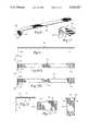
- FIG. 1is a side view of the novel battery pack facing the positive terminal
- FIG. 2is a cross-sectional view of the battery pack taken along lines 2--2 of FIG. 1;
- FIG. 3is a top view of the novel battery pack
- FIG. 4Ais a cross-sectional view taken along lines 4A--4A of FIG. 3;
- FIG. 4Bis a side view of the battery pack facing the negative terminal
- FIG. 5Ais a bottom view of the novel battery pack
- FIG. 5Bis a cross-section through FIG. 1 illustrating the housing insulating the negative terminal
- FIG. 6is a side view of the lower portion of the battery pack illustrating the locking cap
- FIG. 7is a top view of the locking cap itself
- FIG. 8is an isometric view of the ribbon conductor used as the negative terminal of the battery pack
- FIG. 9is a side view of the ribbon conductor of FIG. 8;
- FIG. 10Ais a front view of one embodiment of the ribbon conductor of FIG. 8;
- FIG. 10Bis a front view of an alternate embodiment of the ribbon conductor with the fuse element formed therein;
- FIG. 11is an isometric view of the ribbon-type conductor used as the positive terminal
- FIG. 12is a side view of the positive terminal illustrated in FIG. 11;
- FIG. 13is a front view of the positive terminal of FIG. 11;
- FIG. 14is an end view of the positive terminal of FIG. 11;
- FIG. 15is a top view of the end cap; and
- FIG. 16is a cross-sectional view of the end cap of FIG. 15.
- Battery pack 10comprises a plastic housing 12 divided into two halves or a "clamshell" configuration as will be shown hereafter. It is covered with a PVC shrink wrap tubing 14 to assist in forming an integral unit.
- the PVC shrink tubing 14extends from the base of the battery pack upwardly to a gap 24 just below terminals 18, 30 and 22.
- the lower portion of the housing 12 from gap 24 downwardlyhas a slightly smaller diameter than the upper portion such that when the PVC shrink tubing is tightly shrunk around the housing 12, there will be the small gap 24 which does not exceed 0.040".
- the shrink wrap tubing 14has a thickness of approximately 0.005", which brings the diameter of the lower section of the housing 12 to the diameter of the upper portion above gap 24.
- a gap 17 in housing 12exposes the positive terminal 18 for a short distance along the side of the battery pack 10.
- an opening 19 in the casing 12exposes the outer casing 30 of the uppermost battery which is the negative terminal for that battery.
- Three batteries 26, 28 and 30are shown placed in an end-to-end relationship in the housing 12 in FIG. 2 although more or less could be used.
- An electrical connection 34is formed as a fusible element as will be shown hereafter and is placed in the space formed by a spacer ring shown in cross section as numerals 36 and 38 that separates batteries 26 and 28 and electrically couples battery 26 to battery 28. In the event of excessive current drain, fusible element 34 opens the circuit so that current can no longer flow.
- Cells 26, 28 and 30may, for example only, be 1.2 volts each, thus making the entire battery pack voltage 3.6 volts when measured from the positive terminal to the negative terminal.
- the potential of the casing of cell 30 with respect to the base 40 of battery cell 26is 2.4 volts in the example given.
- the opening 19 in the housing 12provides access to the casing of cell 30, thus providing 2.4 volts that may be used to reduce the speed of the motor in which the device is placed.
- the positive terminal 18 exposed in the opening 17 of the housing 12extends upwardly and across the top of cell 30 where it may be attached in any well known manner such as by welding to the positive terminal 20 of cell 30.
- positive terminal 18may be accessed from either the side or the top of the battery pack 10 continuously from the center to the side.
- the base of the left half 44 of housing 12 shown in FIG. 2has a projection 48 extending therefrom which is flexible and can be inserted in a corresponding slot in the right half 46 of the housing 12 to lock the halves together.
- the upper portion of the housing 12also has projections which snap into corresponding slots to lock the two halves together.
- a locking cap 16is removably attached to the base of the housing 12 not only to assist in holding the two halves 44 and 46 together but also to insure proper alignment of the interlocking elements so that the battery pack 10 can be inserted properly in the tool in which it is to be used. Also an end cap 42 is associated with the locking cap 16 and the housing 12 to prevent the unit from becoming disassembled.
- FIG. 3is a top view of the novel battery pack 10.
- the positive terminal 18fits in a slot 58 that extends across the top of the housing 12 from one side to and beyond the center thereof. It may then be attached to the positive terminal of the upper cell 30 in any well known means such as by welding at spots 54 and 56.
- the two halves 44 and 46 of the housing 12are held together by projections 60 and 62 on housing section 46 that extend into corresponding slots 61 and 63 in housing section 44.
- Locking cap 16has T-shaped projections 50 and 52 extending upwardly and outwardly for latching into the power tool in which the battery pack is to be inserted as will be shown in more detail hereafter.
- the positive terminal 18can be accessed easily from the side or from an area on the top of the housing that extends continuously more than halfway across the top of the housing 12.
- the negative terminal 22is accessible only from the side of the housing 12 and the tap terminal 30, which is the outer casing of upper cell 30, is also accessible only from the side through opening 19 in the housing 12.
- FIG. 4Ais a cross-sectional view of the casing taken along lines 4A--4A of FIG. 3.
- only one half 48 of the housing 12is illustrated since the section is taken along the lines where the two housing halves 44 and 46 come together.
- the ribbon conductor fuse 34can be seen between and connecting cells 26 and 28. It has been reduced in cross-section as illustrated at 64 in a manner well known in the art by an amount sufficient to "open" when excess current is passed therethrough thus protecting the battery pack 10.
- gap 66 in the housingcan be seen the negative terminal 22 which is the upper portion of an elongated conductive ribbon extending from the bottom of cell 26, where it is attached by any well known means such as welding, and up the side of the housing 12 in a slot formed by the housing as will be more clearly seen in FIG. 4B and FIG. 5B.
- An opening 66, as can best be seen in FIG. 4B, in housing 12exposes the upper portion of the negative terminal 22 for contact with the terminals in the tool in which the battery pack is used.
- projections 60 and 62 from the other housing half 46extend into slots in the top of the other housing half or clamshell 44 for attaching the two clamshells 46 and 44 together.
- the positive terminal 18is shown welded at 54 and 56 to the positive terminal 20 of upper battery cell 30.
- the projection 48from one housing section which extends into a slot on the opposite housing section to latch the bottom portion of the clamshell halves 44 and 46 together.
- FIG. 4Bis a side view of the novel battery pack 10 as viewed facing the negative terminal 22.
- the elongated negative terminal 22generally is recessed in a slot 70 (FIG. 4A) with the front portion thereof exposed as illustrated in FIG. 4B. It is covered entirely only at areas 68 and 72 where the plastic extensions on the two halves come together to provide a covering over the terminal 22.
- the fusible elementmay be formed in the elongated terminal 22 as illustrated at 76. The value of having the fusible element in the negative terminal 22 is to enable it to be exposed in the side of the battery pack so that in the event fuse 76 opens, it can be visible from the outside of the battery pack without disassembling it.
- FIG. 5Ais a bottom view of the novel battery pack 12 housing without the locking cap 16 thereon.
- Projection 48 from clamshell half 44is shown projecting through slot 78 to latch the two bottom halves 44 and 46 together.
- the two vertically extending projections 80 and 82enable the locking cap to be placed thereover and rotated to lock themselves under the projections 80 and 82.
- a projection 84is formed on one side thereof to mate with a corresponding slot in the locking cap such that the locking cap can be placed on the bottom portion of the housing 12 in only one direction.
- FIG. 5Bis a cross-section taken through FIG. 1 and illustrates the slot 70 formed by the housing halves 44 and 46 to encompass and surround the edges of the negative terminal 22 to hold it in place along the side of the housing 12.
- FIG. 6is a side view of the lower part of the battery pack 10 illustrating the locking cap 16.
- the body portions 88 on each sidehave a corresponding T-shaped portion 50 and 52 as shown.
- Each of the T-shaped portions 50 and 52has a transverse portion 84 and an arm 86 that is perpendicular to the transverse portion 84 and which is integrally formed with the body portion 88.
- the depending arm portion 86is narrower in width than the transverse portion 84 thus generally forming a "T" shape.
- the body portions 88 with the T-shaped portions 50 and 52extend into the tool by pressing inwardly on both of the sides 88 to allow the T-shaped portion 50 or 52 to pass over a T-shaped recess in the tool on each side thereof so that the T-shaped projection 50 and 52 will be matched with its corresponding T-shaped recess and lock the battery pack into the tool.
- FIG. 7is a top view of the locking cap 16 illustrating the arms 88 with the T-shaped projections 50 and 52 thereon.
- the center portion of the locking cap 16is open and has diametrically opposed arcuate sections 90 and 92 for receiving the flanges 80 and 82 on the bottom of the battery pack housing 12.
- the projecting ledges 94 and 96will pass over the top of the flanges 80 and 82 on the bottom of the battery housing 12 thus attaching the locking cap 16 to the bottom of the battery pack housing 12.
- An indentation 98mates with the projection 84 on the bottom of the housing 12 when the locking cap 16 is first attached to the base so that flanges 80 and 82 shown in FIG.
- an end cap 42which will be discussed hereafter in relation to FIGS. 15 and 16, has locking tabs which fit in the slots 102 and 104 to prevent rotation of the locking cap 16.
- FIG. 8is an isometric view of the ribbon-type negative terminal 22. It has an elongated body portion 106 with the upper portion 22 serving as the terminal. The lower portion 108 is bent at right angles to the body portion 106 and has a foot portion 109 with weld areas 110 and 112 which can be used to weld the foot portion 108 to the base of the lowest battery cell.
- FIG. 9is a side view of the elongated negative terminal and FIG. 10A is a front view.
- FIG. 10Bis an alternate front view illustrating a fuse portion 76 made by reducing the width of the negative electrode by removing portions thereof in a manner well known in the art sufficient to cause the portion of reduced area 76 to vaporize or melt when current flow exceeds a predetermined amount.
- the importance of placing the fusible element 76 in the negative electrode 22is shown in FIG. 4B because it is visible on the side of the housing 12 thus enabling the user to determine if the fuse has been "blown.”
- FIG. 11is an isometric view of the positive terminal 18. It has a top portion 114 which attaches to the top of the housing 12 and is fastened to the positive terminal of the uppermost battery in some well known means such as weld spots 54 and 56.
- the vertical portion 116which is bent at right angles to the horizontal portion 114 extends partially down the side of the housing 44 in an opening therein and is held in place by lip 21 shown in FIG. 2 with casing or housing 24 in back of it.
- the positive terminal 18is held rigidly in place from the center of the top of the battery pack 10 continuously to one edge and down the side thereof a predetermined distance so that contact with the positive terminal can be made either with the top or the side of the battery pack.
- FIG. 12is a side view of the positive terminal 18, FIG. 13 is a bottom view and FIG. 14 is an end view.
- FIG. 15is a top view of the end cap 42.
- End cap 42has a circular body 117 with pliable projections 118 and 120 thereon that mate with slots 102 and 104 respectively in the locking cap 16.
- the projections 118 and 120are bent inwardly to allow them to bypass the arcuate portions 90 and 92 and then snap into the slots 102 and 104 to hold the cap in place.
- Raised portions 122 and 124rest against flanges 80 and 82. This combined with projections 118 and 120 resting against the side of ledges 94 and 96 is what locks the cap 16 in place preventing rotation of lock cap 16.
- the raised portions 122 and 124contact the locking cap 16 and thus limit the distance the end cap 46 can be inserted into the locking cap 16.
- a novel battery packfor use in a power tool that utilizes a plurality of axially aligned battery cells forming a series circuit.
- the cellshave an anode at one end and a cathode at the other end as outputs.
- a housingsurrounds and contains the battery cells and a positive and a negative terminal are exposed in one end of the housing for forming external electrical voltage connections.
- a ribbon-type conductorhas one end forming the exposed negative terminal and the other end coupled to the cathode of the series coupled battery cells.
- the positive terminalis coupled to the anode of the series circuit and extends continuously in an exposed condition across the top of the battery pack and down the side of the battery pack a predetermined distance.
- the housingitself has a slot down the side thereof for supporting the ribbon-type negative conductor and insulating the negative conductor from the battery casings which serve as the cathodes for each of the cells.
- a locking cap and end capare removably attached to the base of the power pack for holding all the elements in proper aligned relationship and enabling the battery pack to be removably connected to a power tool.
- the positive and negative terminalsare spaced from each other 90° at the top of the battery pack.
- An intermediate voltage terminalis exposed in an opening between the positive and negative terminals such that all three terminals are exposed within a 90° arc.
- the housingis formed of first and second halves formed of a non-metallic material such as plastic with mating locking tabs on each end of the halves to assist in locking the halves together. Slots are formed in the wall of the halves for receiving and containing the ribbon connector forming the negative terminal and the ribbon conductor forming the positive terminal.
- a fuse elementcan be formed in the circuit either between two of the axially aligned cells or in the elongated negative terminal.
- the fuse elementcan be made by reducing the cross-sectional area of the ribbon-type conductor as is well known in the art to provide a cross-sectional area that will conduct current up to a predetermined amount and then melt, thus opening the circuit.
- the locking capthat is removably coupled to one end of the housing has first and second resilient T-shaped projections extending upwardly from the cap body portion in spaced relationship with the housing.
- the T-shaped projectionsare capable of being flexed inwardly to allow them to enter the power tool and lockingly engage a corresponding recess with the power tool.
- the locking caphas an opening in the center thereof with first and second horizontal projections extending inwardly from the opening.
- First and second corresponding spaced flangesare formed on the bottom of the housing such that the flanges can be mated with and rotated under the horizontal projections on the cap to lock the cap to the housing.
- the locking caphas a flat spot on one side of the body portion spaced at right angles with respect to the upwardly extending T-shaped projections.
- a flat spotis formed on one side of the locking cap body portion and is spaced 90° with respect to the upwardly extending projections.
- a recessis formed on one of the horizontal cap projections and a projection is formed on the base of the battery housing such that the locking cap will attach to the battery housing in only one position where the recess receives the projection in mating relationship so that the flat spot on one side of the locking cap body portion is always in a fixed position with respect to the battery housing.
Landscapes
- Chemical & Material Sciences (AREA)
- Chemical Kinetics & Catalysis (AREA)
- Electrochemistry (AREA)
- General Chemical & Material Sciences (AREA)
- Battery Mounting, Suspending (AREA)
- Connection Of Batteries Or Terminals (AREA)
Abstract
Description
Claims (17)
Priority Applications (1)
| Application Number | Priority Date | Filing Date | Title |
|---|---|---|---|
| US07/743,166US5122427A (en) | 1991-08-09 | 1991-08-09 | Battery pack |
Applications Claiming Priority (1)
| Application Number | Priority Date | Filing Date | Title |
|---|---|---|---|
| US07/743,166US5122427A (en) | 1991-08-09 | 1991-08-09 | Battery pack |
Publications (1)
| Publication Number | Publication Date |
|---|---|
| US5122427Atrue US5122427A (en) | 1992-06-16 |
Family
ID=24987751
Family Applications (1)
| Application Number | Title | Priority Date | Filing Date |
|---|---|---|---|
| US07/743,166Expired - LifetimeUS5122427A (en) | 1991-08-09 | 1991-08-09 | Battery pack |
Country Status (1)
| Country | Link |
|---|---|
| US (1) | US5122427A (en) |
Cited By (46)
| Publication number | Priority date | Publication date | Assignee | Title |
|---|---|---|---|---|
| USD345727S (en) | 1991-08-09 | 1994-04-05 | Skil and S-B Power Tool Company | Rechargeable battery pack for electric power tools |
| US5321584A (en)* | 1993-01-19 | 1994-06-14 | Tek Electronics Manufacturing Corporation | Battery and holder assembly for use with a battery operated touch pen |
| WO1994023460A1 (en)* | 1993-04-05 | 1994-10-13 | Black & Decker Inc. | Battery pack for cordless device |
| US5368954A (en)* | 1990-10-02 | 1994-11-29 | Robert Bosch Gmbh | Device on electric power hand tools |
| EP0629017A1 (en)* | 1993-06-02 | 1994-12-14 | Texas Instruments France | Improvements in or relating to battery pack arrangements |
| US5409167A (en)* | 1993-08-24 | 1995-04-25 | Borod; Murray | Hygienic spray apparatus |
| US5432017A (en)* | 1992-09-14 | 1995-07-11 | Motorola, Inc. | Battery pack and method of forming same |
| USD360397S (en) | 1993-06-03 | 1995-07-18 | Wells James M | Battery pack for portable electronic devices |
| USD376579S (en) | 1995-08-09 | 1996-12-17 | Black & Decker Inc. | Battery pack |
| US5681667A (en)* | 1994-08-11 | 1997-10-28 | Black & Decker Inc. | Battery pack retaining latch for cordless device |
| US5764029A (en)* | 1996-12-30 | 1998-06-09 | Coyle; Tim | Portable rechargeable battery adaptor assembly |
| US5792573A (en)* | 1994-06-10 | 1998-08-11 | Pitzen; James F. | Rechargeable battery adapted to be attached to orthopedic device |
| USD401901S (en) | 1996-11-20 | 1998-12-01 | Black & Decker Inc. | Battery pack contact end |
| US5854549A (en)* | 1996-09-24 | 1998-12-29 | Motorola, Inc. | Contact arrangement having an auxiliary contact |
| US5919585A (en)* | 1993-04-05 | 1999-07-06 | Black & Decker, Inc. | Battery pack for cordless device |
| USRE37092E1 (en) | 1993-01-13 | 2001-03-13 | Streamlight, Inc. | Flashlight and recharging system therefor |
| US6224997B1 (en)* | 1999-04-08 | 2001-05-01 | Nick Papadopoulos | Downhole battery case |
| US6656626B1 (en) | 1999-06-01 | 2003-12-02 | Porter-Cable Corporation | Cordless power tool battery release mechanism |
| US20040072064A1 (en)* | 2001-08-24 | 2004-04-15 | Turner Terry L. | Power tool with battery pack ejector |
| US6732449B2 (en) | 2000-09-15 | 2004-05-11 | Walter Evanyk | Dryer/blower appliance with efficient waste heat dissipation |
| US20040126657A1 (en)* | 2002-12-27 | 2004-07-01 | Yu-Lin Chung | Battery structure |
| US20050183283A1 (en)* | 2004-02-19 | 2005-08-25 | Powerpulse Technologies, L.P. | Heating element and circuit for a hair management system |
| US20050270754A1 (en)* | 2004-06-05 | 2005-12-08 | Heiko Roehm | Electrical tool |
| US20050280388A1 (en)* | 2004-05-20 | 2005-12-22 | Powerpulse Technologies, L.P. | Circuit for energy conservation |
| US20060032076A1 (en)* | 2004-08-10 | 2006-02-16 | Powerpulse Technologies, L.P. | Portable energy consuming device |
| US20060199073A1 (en)* | 2004-03-12 | 2006-09-07 | Rainer Glauning | Electric hand machine-tool and power supply module for an electric hand machine tool |
| USD528070S1 (en)* | 2005-06-21 | 2006-09-12 | Samson Bright Industrial Company Limited | Battery pack |
| USD528503S1 (en)* | 2005-09-02 | 2006-09-19 | Samson Bright Industrial Company Limited | Battery pack for combined electric pepper and salt mill |
| USD528974S1 (en)* | 2005-06-21 | 2006-09-26 | Samson Bright Industrial Company Limited | Battery pack |
| US20060267548A1 (en)* | 2005-05-17 | 2006-11-30 | Milwaukee Electric Tool Corporation | Power tool, battery, charger and method of operating the same |
| US20060267556A1 (en)* | 2005-05-17 | 2006-11-30 | Milwaukee Electric Tool Corporation | Power tool, battery, charger and method of operating the same |
| US20070089760A1 (en)* | 2005-10-21 | 2007-04-26 | Evanyk Walter R | Hair curler/hair brush |
| USD562226S1 (en)* | 2006-05-17 | 2008-02-19 | Milwaukee Electric Tool Corporation | Power tool battery |
| EP1908559A1 (en)* | 2006-10-07 | 2008-04-09 | Metabowerke GmbH | Electric hand tool |
| US20090047572A1 (en)* | 2007-08-16 | 2009-02-19 | Micropower Electronics, Inc. | Controlled pressure release for packaged batteries and associated systems and methods |
| US20090092894A1 (en)* | 2007-10-09 | 2009-04-09 | Samsung Sdi Co., Ltd. | Rechargeable battery and battery module |
| US20090111009A1 (en)* | 2007-10-27 | 2009-04-30 | Bayerische Motoren Werke Aktiengesellschaft | Apparatus for Supplying Power to a Motor Vehicle |
| USD603331S1 (en)* | 2009-03-12 | 2009-11-03 | Koninklijke Philips Electronics N.V. | Battery for lamp |
| US20100173519A1 (en)* | 2005-04-27 | 2010-07-08 | Martin Diehl | Battery-Operated Appliances |
| US7868590B2 (en) | 2001-11-09 | 2011-01-11 | Milwaukee Electric Tool Corporation | Electrical component, such as a radio, MP3 player, audio component, battery charger, radio/charger, MP3 player/radio, MP3 player/charger or MP3 player/radio/charger, having a selectively connectable battery charger |
| US8482608B1 (en)* | 2009-03-18 | 2013-07-09 | Shaun C. Sandoval | Trans-cam magnetically mounted camera housing device |
| WO2013169761A1 (en)* | 2012-05-07 | 2013-11-14 | Milwaukee Electric Tool Corporation | Twist on battery pack |
| US10158105B2 (en) | 2016-03-16 | 2018-12-18 | Tti (Macao Commercial Offshore) Limited | Battery pack latch mechanism |
| CN110770937A (en)* | 2017-06-14 | 2020-02-07 | 米沃奇电动工具公司 | Arrangement for preventing intrusion into electrical components of a battery |
| US11289924B2 (en)* | 2019-08-09 | 2022-03-29 | Techtronic Cordless Gp | Battery pack including a high- and low-current discharge terminals |
| USD1071162S1 (en)* | 2020-12-07 | 2025-04-15 | Shl Medical Ag | Power pack for a medical injection device |
Citations (4)
| Publication number | Priority date | Publication date | Assignee | Title |
|---|---|---|---|---|
| US3657021A (en)* | 1970-04-20 | 1972-04-18 | Mallory Battery Canada | Emergency power pack |
| US4584250A (en)* | 1984-01-05 | 1986-04-22 | General Electric Company | Battery with slideably retractable attachment means |
| US4871629A (en)* | 1988-02-04 | 1989-10-03 | Black & Decker Inc. | Latching arrangement for battery packs |
| US4904549A (en)* | 1988-11-04 | 1990-02-27 | Motorola, Inc. | Battery housing with integral latch and positive displacement apparatus |
- 1991
- 1991-08-09USUS07/743,166patent/US5122427A/ennot_activeExpired - Lifetime
Patent Citations (4)
| Publication number | Priority date | Publication date | Assignee | Title |
|---|---|---|---|---|
| US3657021A (en)* | 1970-04-20 | 1972-04-18 | Mallory Battery Canada | Emergency power pack |
| US4584250A (en)* | 1984-01-05 | 1986-04-22 | General Electric Company | Battery with slideably retractable attachment means |
| US4871629A (en)* | 1988-02-04 | 1989-10-03 | Black & Decker Inc. | Latching arrangement for battery packs |
| US4904549A (en)* | 1988-11-04 | 1990-02-27 | Motorola, Inc. | Battery housing with integral latch and positive displacement apparatus |
Cited By (88)
| Publication number | Priority date | Publication date | Assignee | Title |
|---|---|---|---|---|
| US5368954A (en)* | 1990-10-02 | 1994-11-29 | Robert Bosch Gmbh | Device on electric power hand tools |
| USD345727S (en) | 1991-08-09 | 1994-04-05 | Skil and S-B Power Tool Company | Rechargeable battery pack for electric power tools |
| US5432017A (en)* | 1992-09-14 | 1995-07-11 | Motorola, Inc. | Battery pack and method of forming same |
| USRE37092E1 (en) | 1993-01-13 | 2001-03-13 | Streamlight, Inc. | Flashlight and recharging system therefor |
| US5321584A (en)* | 1993-01-19 | 1994-06-14 | Tek Electronics Manufacturing Corporation | Battery and holder assembly for use with a battery operated touch pen |
| KR100306734B1 (en)* | 1993-04-05 | 2001-11-30 | 배리 이. 도이치 | Battery Packs for Wireless Devices |
| US20030224247A1 (en)* | 1993-04-05 | 2003-12-04 | Wheeler Dale K. | Battery pack for cordless device |
| US7550213B2 (en) | 1993-04-05 | 2009-06-23 | Black & Decker Inc. | Tool system having rechargeable battery pack |
| US5489484A (en)* | 1993-04-05 | 1996-02-06 | Black & Decker Inc. | Battery pack for cordless device |
| US6602634B1 (en)* | 1993-04-05 | 2003-08-05 | Black & Decker Inc. | Battery pack for cordless device |
| US5620808A (en)* | 1993-04-05 | 1997-04-15 | Black & Decker Inc. | Battery pack for cordless device |
| US20080008929A1 (en)* | 1993-04-05 | 2008-01-10 | Wheeler Dale K | Tool system having rechargeable battery pack |
| US5919585A (en)* | 1993-04-05 | 1999-07-06 | Black & Decker, Inc. | Battery pack for cordless device |
| US7273676B2 (en)* | 1993-04-05 | 2007-09-25 | Black & Decker Inc. | Battery pack for cordless device |
| USRE37226E1 (en)* | 1993-04-05 | 2001-06-12 | Black & Decker Corporation | Battery pack for cordless device |
| WO1994023460A1 (en)* | 1993-04-05 | 1994-10-13 | Black & Decker Inc. | Battery pack for cordless device |
| US5545491A (en)* | 1993-06-02 | 1996-08-13 | Texas Instruments Incorporated | Relating to battery pack arrangements |
| EP0629017A1 (en)* | 1993-06-02 | 1994-12-14 | Texas Instruments France | Improvements in or relating to battery pack arrangements |
| USD360397S (en) | 1993-06-03 | 1995-07-18 | Wells James M | Battery pack for portable electronic devices |
| US5409167A (en)* | 1993-08-24 | 1995-04-25 | Borod; Murray | Hygienic spray apparatus |
| US5792573A (en)* | 1994-06-10 | 1998-08-11 | Pitzen; James F. | Rechargeable battery adapted to be attached to orthopedic device |
| USRE40681E1 (en)* | 1994-06-10 | 2009-03-24 | Linvatec Corporation | Combination rechargeable, detachable battery system and power tool |
| USRE40848E1 (en)* | 1994-06-10 | 2009-07-14 | Pitzen James F | Combination rechargeable, detachable battery system and power tool |
| US5800940A (en)* | 1994-08-11 | 1998-09-01 | Black & Decker Inc. | Battery pack retaining latch for cordless device |
| US5681667A (en)* | 1994-08-11 | 1997-10-28 | Black & Decker Inc. | Battery pack retaining latch for cordless device |
| US5718985A (en)* | 1994-08-11 | 1998-02-17 | Black & Decker Inc. | Battery pack retaining latch for cordless device |
| USD376579S (en) | 1995-08-09 | 1996-12-17 | Black & Decker Inc. | Battery pack |
| US5854549A (en)* | 1996-09-24 | 1998-12-29 | Motorola, Inc. | Contact arrangement having an auxiliary contact |
| USD401901S (en) | 1996-11-20 | 1998-12-01 | Black & Decker Inc. | Battery pack contact end |
| US5764029A (en)* | 1996-12-30 | 1998-06-09 | Coyle; Tim | Portable rechargeable battery adaptor assembly |
| US6224997B1 (en)* | 1999-04-08 | 2001-05-01 | Nick Papadopoulos | Downhole battery case |
| US6656626B1 (en) | 1999-06-01 | 2003-12-02 | Porter-Cable Corporation | Cordless power tool battery release mechanism |
| US20040081883A1 (en)* | 1999-06-01 | 2004-04-29 | Tom Mooty | Cordless power tool battery release mechanism |
| US7429430B2 (en) | 1999-06-01 | 2008-09-30 | Black & Decker Inc. | Cordless power tool battery release mechanism |
| US6732449B2 (en) | 2000-09-15 | 2004-05-11 | Walter Evanyk | Dryer/blower appliance with efficient waste heat dissipation |
| US20100000067A1 (en)* | 2001-08-24 | 2010-01-07 | Black & Decker Inc. | Battery For A Power Tool With A Battery Pack Ejector |
| US20040072064A1 (en)* | 2001-08-24 | 2004-04-15 | Turner Terry L. | Power tool with battery pack ejector |
| US7661486B2 (en) | 2001-08-24 | 2010-02-16 | Black & Decker Inc. | Power tool with battery pack ejector |
| US8312937B2 (en) | 2001-08-24 | 2012-11-20 | Black & Decker Inc. | Battery for a power tool with a battery pack ejector |
| US8181717B2 (en) | 2001-08-24 | 2012-05-22 | Black & Decker Inc. | Power tool with battery pack ejector |
| US20040197175A1 (en)* | 2001-08-24 | 2004-10-07 | Turner Terry L. | Power tool with battery pack ejector |
| US6729413B2 (en) | 2001-08-24 | 2004-05-04 | Black & Decker Inc. | Power tool with battery pack ejector |
| US8203307B2 (en) | 2001-11-09 | 2012-06-19 | Milwaukee Electric Tool Corporation | Audio and charging system with audio device, power tool battery, and external battery charger |
| US7868590B2 (en) | 2001-11-09 | 2011-01-11 | Milwaukee Electric Tool Corporation | Electrical component, such as a radio, MP3 player, audio component, battery charger, radio/charger, MP3 player/radio, MP3 player/charger or MP3 player/radio/charger, having a selectively connectable battery charger |
| US6949311B2 (en)* | 2002-12-27 | 2005-09-27 | Yu-Lin Chung | Battery structure |
| US20040126657A1 (en)* | 2002-12-27 | 2004-07-01 | Yu-Lin Chung | Battery structure |
| US20050183283A1 (en)* | 2004-02-19 | 2005-08-25 | Powerpulse Technologies, L.P. | Heating element and circuit for a hair management system |
| US8033344B2 (en)* | 2004-03-12 | 2011-10-11 | Robert Bosch Gmbh | Power supply module for an electric power tool |
| US20060199073A1 (en)* | 2004-03-12 | 2006-09-07 | Rainer Glauning | Electric hand machine-tool and power supply module for an electric hand machine tool |
| US7552780B2 (en)* | 2004-03-12 | 2009-06-30 | Robert Bosch Gmbh | Electric hand machine-tool and power supply module for an electric hand machine tool |
| US20050280388A1 (en)* | 2004-05-20 | 2005-12-22 | Powerpulse Technologies, L.P. | Circuit for energy conservation |
| US7508679B2 (en)* | 2004-06-05 | 2009-03-24 | Robert Bosch Gmbh | Electrical tool |
| US20050270754A1 (en)* | 2004-06-05 | 2005-12-08 | Heiko Roehm | Electrical tool |
| US20060032076A1 (en)* | 2004-08-10 | 2006-02-16 | Powerpulse Technologies, L.P. | Portable energy consuming device |
| US20100173519A1 (en)* | 2005-04-27 | 2010-07-08 | Martin Diehl | Battery-Operated Appliances |
| US8250763B2 (en) | 2005-04-27 | 2012-08-28 | The Gillette Company | Battery-operated razor |
| EP2221902A1 (en)* | 2005-04-27 | 2010-08-25 | The Gillette Company | Battery operated appliances |
| US20090031865A1 (en)* | 2005-05-17 | 2009-02-05 | Alberti Daniel J | Power tool, battery, charger and method of operating the same |
| US7557534B2 (en) | 2005-05-17 | 2009-07-07 | Milwaukee Electric Tool Corporation | Power tool, battery, charger and method of operating the same |
| US7932695B2 (en) | 2005-05-17 | 2011-04-26 | Milwaukee Electric Tool Corporation | Power tool, battery, charger and method of operating the same |
| US20060267548A1 (en)* | 2005-05-17 | 2006-11-30 | Milwaukee Electric Tool Corporation | Power tool, battery, charger and method of operating the same |
| US7649337B2 (en) | 2005-05-17 | 2010-01-19 | Milwaukee Electric Tool Corporation | Power tool including a fuel gauge and method of operating the same |
| US20090102420A1 (en)* | 2005-05-17 | 2009-04-23 | Nancy Uehlein-Proctor | Power tool, battery, charger and method of operating the same |
| US7814816B2 (en) | 2005-05-17 | 2010-10-19 | Milwaukee Electric Tool Corporation | Power tool, battery, charger and method of operating the same |
| US20060267556A1 (en)* | 2005-05-17 | 2006-11-30 | Milwaukee Electric Tool Corporation | Power tool, battery, charger and method of operating the same |
| USD528070S1 (en)* | 2005-06-21 | 2006-09-12 | Samson Bright Industrial Company Limited | Battery pack |
| USD528974S1 (en)* | 2005-06-21 | 2006-09-26 | Samson Bright Industrial Company Limited | Battery pack |
| USD528503S1 (en)* | 2005-09-02 | 2006-09-19 | Samson Bright Industrial Company Limited | Battery pack for combined electric pepper and salt mill |
| US20070089760A1 (en)* | 2005-10-21 | 2007-04-26 | Evanyk Walter R | Hair curler/hair brush |
| USD562226S1 (en)* | 2006-05-17 | 2008-02-19 | Milwaukee Electric Tool Corporation | Power tool battery |
| EP1908559A1 (en)* | 2006-10-07 | 2008-04-09 | Metabowerke GmbH | Electric hand tool |
| US20090047572A1 (en)* | 2007-08-16 | 2009-02-19 | Micropower Electronics, Inc. | Controlled pressure release for packaged batteries and associated systems and methods |
| EP2048723A1 (en)* | 2007-10-09 | 2009-04-15 | Samsung SDI Co., Ltd. | Battery module |
| US8142921B2 (en) | 2007-10-09 | 2012-03-27 | Samsung Sdi Co., Ltd. | Rechargeable battery and battery module |
| US20090092894A1 (en)* | 2007-10-09 | 2009-04-09 | Samsung Sdi Co., Ltd. | Rechargeable battery and battery module |
| US20090111009A1 (en)* | 2007-10-27 | 2009-04-30 | Bayerische Motoren Werke Aktiengesellschaft | Apparatus for Supplying Power to a Motor Vehicle |
| US8889282B2 (en)* | 2007-10-27 | 2014-11-18 | Bayerische Motoren Werke Aktiengesellschaft | Apparatus for supplying power to a motor vehicle |
| USD603331S1 (en)* | 2009-03-12 | 2009-11-03 | Koninklijke Philips Electronics N.V. | Battery for lamp |
| US8482608B1 (en)* | 2009-03-18 | 2013-07-09 | Shaun C. Sandoval | Trans-cam magnetically mounted camera housing device |
| US8878490B2 (en) | 2012-05-07 | 2014-11-04 | Milwaukee Electric Tool Corporation | Twist on battery pack |
| WO2013169761A1 (en)* | 2012-05-07 | 2013-11-14 | Milwaukee Electric Tool Corporation | Twist on battery pack |
| US10158105B2 (en) | 2016-03-16 | 2018-12-18 | Tti (Macao Commercial Offshore) Limited | Battery pack latch mechanism |
| US10892451B2 (en) | 2016-03-16 | 2021-01-12 | Tti (Macao Commercial Offshore) Limited | Battery pack latch mechanism |
| CN110770937A (en)* | 2017-06-14 | 2020-02-07 | 米沃奇电动工具公司 | Arrangement for preventing intrusion into electrical components of a battery |
| CN110770937B (en)* | 2017-06-14 | 2023-08-22 | 米沃奇电动工具公司 | Arrangement for preventing intrusion into electrical components of a battery |
| US11289924B2 (en)* | 2019-08-09 | 2022-03-29 | Techtronic Cordless Gp | Battery pack including a high- and low-current discharge terminals |
| US11881733B2 (en) | 2019-08-09 | 2024-01-23 | Techtronic Cordless Gp | Battery pack including a high- and low-current discharge terminals |
| USD1071162S1 (en)* | 2020-12-07 | 2025-04-15 | Shl Medical Ag | Power pack for a medical injection device |
Similar Documents
| Publication | Publication Date | Title |
|---|---|---|
| US5122427A (en) | Battery pack | |
| EP2224517B1 (en) | Connector assembly and battery pack having the same | |
| US11654782B2 (en) | Battery module | |
| CN100418262C (en) | secondary battery | |
| US5145417A (en) | Terminal block assembly for hermetic terminal structure | |
| EP0332475B1 (en) | Battery charger and battery packs | |
| CN102326278B (en) | Rechargeable battery pack having novel structure | |
| TW200527741A (en) | Lead member and secondary battery module with the same | |
| JP5364681B2 (en) | Battery assembly | |
| JPH1092541A (en) | Rotating connector | |
| EP3511971B1 (en) | Multi-part symmetrical fuse assembly | |
| WO2024042813A1 (en) | Fuse | |
| KR102839733B1 (en) | Battery module with sealing performance for hv terminal and battery pack comprising the same | |
| US7531985B2 (en) | Pack case for secondary battery | |
| US6618273B2 (en) | Trace fuse | |
| JP2003323870A (en) | Battery pack | |
| JP3221867B2 (en) | Secondary battery with battery protection circuit | |
| JP3604829B2 (en) | Battery pack | |
| JPH08185837A (en) | Pack battery | |
| CA1340662C (en) | Cordless tool battery housing and charging system | |
| JP2000340200A (en) | Battery pack | |
| KR20060088230A (en) | PCM connection structure of built-in lithium ion battery | |
| EP4593176A1 (en) | Battery pack | |
| JP3939018B2 (en) | Pack battery | |
| JP3688236B2 (en) | Protector unit |
Legal Events
| Date | Code | Title | Description |
|---|---|---|---|
| AS | Assignment | Owner name:SKIL CORPORATION, A CORPORATION OF DE Free format text:ASSIGNMENT OF ASSIGNORS INTEREST.;ASSIGNORS:FLOWERS, DALE M.;HARTMANN, JAMES R.;REEL/FRAME:005817/0090 Effective date:19910808 | |
| STCF | Information on status: patent grant | Free format text:PATENTED CASE | |
| AS | Assignment | Owner name:S-B POWER TOOL COMPANY, ILLINOIS Free format text:ASSIGNMENT OF ASSIGNORS INTEREST.;ASSIGNOR:SKIL CORPORATION;REEL/FRAME:006495/0992 Effective date:19920924 | |
| CC | Certificate of correction | ||
| FEPP | Fee payment procedure | Free format text:PAYOR NUMBER ASSIGNED (ORIGINAL EVENT CODE: ASPN); ENTITY STATUS OF PATENT OWNER: LARGE ENTITY | |
| FPAY | Fee payment | Year of fee payment:4 | |
| REFU | Refund | Free format text:REFUND PROCESSED. MAINTENANCE FEE HAS ALREADY BEEN PAID (ORIGINAL EVENT CODE: R160); ENTITY STATUS OF PATENT OWNER: LARGE ENTITY | |
| FEPP | Fee payment procedure | Free format text:PAYER NUMBER DE-ASSIGNED (ORIGINAL EVENT CODE: RMPN); ENTITY STATUS OF PATENT OWNER: LARGE ENTITY Free format text:PAYOR NUMBER ASSIGNED (ORIGINAL EVENT CODE: ASPN); ENTITY STATUS OF PATENT OWNER: LARGE ENTITY | |
| FPAY | Fee payment | Year of fee payment:8 | |
| FEPP | Fee payment procedure | Free format text:PAYER NUMBER DE-ASSIGNED (ORIGINAL EVENT CODE: RMPN); ENTITY STATUS OF PATENT OWNER: LARGE ENTITY Free format text:PAYOR NUMBER ASSIGNED (ORIGINAL EVENT CODE: ASPN); ENTITY STATUS OF PATENT OWNER: LARGE ENTITY | |
| FEPP | Fee payment procedure | Free format text:PAYER NUMBER DE-ASSIGNED (ORIGINAL EVENT CODE: RMPN); ENTITY STATUS OF PATENT OWNER: LARGE ENTITY Free format text:PAYOR NUMBER ASSIGNED (ORIGINAL EVENT CODE: ASPN); ENTITY STATUS OF PATENT OWNER: LARGE ENTITY | |
| REMI | Maintenance fee reminder mailed | ||
| FPAY | Fee payment | Year of fee payment:12 | |
| SULP | Surcharge for late payment | Year of fee payment:11 | |
| AS | Assignment | Owner name:S-B POWER TOOL CORPORATION, ILLINOIS Free format text:SECRETARY'S CERTIFICATE;ASSIGNOR:S- B POWER TOOL COMPANY;REEL/FRAME:014609/0996 Effective date:20020703 Owner name:CREDO TECHNOLOGY CORPORATION, DELAWARE Free format text:ASSIGNMENT OF ASSIGNORS INTEREST;ASSIGNOR:ROBERT BOSCH TOOL CORPORATION;REEL/FRAME:014615/0215 Effective date:20030101 Owner name:ROBERT BOSCH TOOL CORPORATION, ILLINOIS Free format text:COMBINED MERGER AND CHANGE OF NAME;ASSIGNOR:S-B POWER TOOL CORPORATION;REEL/FRAME:014615/0197 Effective date:20021227 | |
| FEPP | Fee payment procedure | Free format text:PAYER NUMBER DE-ASSIGNED (ORIGINAL EVENT CODE: RMPN); ENTITY STATUS OF PATENT OWNER: LARGE ENTITY Free format text:PAYOR NUMBER ASSIGNED (ORIGINAL EVENT CODE: ASPN); ENTITY STATUS OF PATENT OWNER: LARGE ENTITY |