US5122140A - Dynamic external fixation device - Google Patents
Dynamic external fixation deviceDownload PDFInfo
- Publication number
- US5122140A US5122140AUS07/572,523US57252390AUS5122140AUS 5122140 AUS5122140 AUS 5122140AUS 57252390 AUS57252390 AUS 57252390AUS 5122140 AUS5122140 AUS 5122140A
- Authority
- US
- United States
- Prior art keywords
- rod
- fixation device
- fixation
- casing
- arc
- Prior art date
- Legal status (The legal status is an assumption and is not a legal conclusion. Google has not performed a legal analysis and makes no representation as to the accuracy of the status listed.)
- Expired - Lifetime
Links
- 210000000988bone and boneAnatomy0.000claimsabstractdescription13
- 230000008685targetingEffects0.000claimsabstractdescription11
- 230000000712assemblyEffects0.000claimsabstractdescription10
- 238000000429assemblyMethods0.000claimsabstractdescription10
- 230000014759maintenance of locationEffects0.000claimsdescription6
- 230000006835compressionEffects0.000claimsdescription2
- 238000007906compressionMethods0.000claimsdescription2
- 238000005096rolling processMethods0.000claims1
- 210000000707wristAnatomy0.000abstractdescription8
- 210000003484anatomyAnatomy0.000description3
- 238000007596consolidation processMethods0.000description3
- 230000000694effectsEffects0.000description3
- 210000002105tongueAnatomy0.000description3
- XUIMIQQOPSSXEZ-UHFFFAOYSA-NSiliconChemical compound[Si]XUIMIQQOPSSXEZ-UHFFFAOYSA-N0.000description2
- 210000000245forearmAnatomy0.000description2
- 210000001037metacarpusAnatomy0.000description2
- 229910052710siliconInorganic materials0.000description2
- 239000010703siliconSubstances0.000description2
- 210000000078clawAnatomy0.000description1
- 239000000470constituentSubstances0.000description1
- 238000010276constructionMethods0.000description1
- 230000008602contractionEffects0.000description1
- 230000006837decompressionEffects0.000description1
- 230000007423decreaseEffects0.000description1
- 238000006073displacement reactionMethods0.000description1
- 239000013536elastomeric materialSubstances0.000description1
- 230000008030eliminationEffects0.000description1
- 238000003379elimination reactionMethods0.000description1
- 230000003100immobilizing effectEffects0.000description1
- 210000003041ligamentAnatomy0.000description1
- 229910001234light alloyInorganic materials0.000description1
- 238000000034methodMethods0.000description1
- 238000012544monitoring processMethods0.000description1
- 230000001737promoting effectEffects0.000description1
- 230000001105regulatory effectEffects0.000description1
- 238000010079rubber tappingMethods0.000description1
- 230000009291secondary effectEffects0.000description1
- 239000010935stainless steelSubstances0.000description1
- 229910001220stainless steelInorganic materials0.000description1
Images


Classifications
- A—HUMAN NECESSITIES
- A61—MEDICAL OR VETERINARY SCIENCE; HYGIENE
- A61F—FILTERS IMPLANTABLE INTO BLOOD VESSELS; PROSTHESES; DEVICES PROVIDING PATENCY TO, OR PREVENTING COLLAPSING OF, TUBULAR STRUCTURES OF THE BODY, e.g. STENTS; ORTHOPAEDIC, NURSING OR CONTRACEPTIVE DEVICES; FOMENTATION; TREATMENT OR PROTECTION OF EYES OR EARS; BANDAGES, DRESSINGS OR ABSORBENT PADS; FIRST-AID KITS
- A61F2/00—Filters implantable into blood vessels; Prostheses, i.e. artificial substitutes or replacements for parts of the body; Appliances for connecting them with the body; Devices providing patency to, or preventing collapsing of, tubular structures of the body, e.g. stents
- A61F2/02—Prostheses implantable into the body
- A61F2/30—Joints
- A61F2/42—Joints for wrists or ankles; for hands, e.g. fingers; for feet, e.g. toes
- A—HUMAN NECESSITIES
- A61—MEDICAL OR VETERINARY SCIENCE; HYGIENE
- A61B—DIAGNOSIS; SURGERY; IDENTIFICATION
- A61B17/00—Surgical instruments, devices or methods
- A61B17/56—Surgical instruments or methods for treatment of bones or joints; Devices specially adapted therefor
- A61B17/58—Surgical instruments or methods for treatment of bones or joints; Devices specially adapted therefor for osteosynthesis, e.g. bone plates, screws or setting implements
- A61B17/60—Surgical instruments or methods for treatment of bones or joints; Devices specially adapted therefor for osteosynthesis, e.g. bone plates, screws or setting implements for external osteosynthesis, e.g. distractors, contractors
- A61B17/64—Devices extending alongside the bones to be positioned
- A61B17/6425—Devices extending alongside the bones to be positioned specially adapted to be fitted across a bone joint
- A—HUMAN NECESSITIES
- A61—MEDICAL OR VETERINARY SCIENCE; HYGIENE
- A61F—FILTERS IMPLANTABLE INTO BLOOD VESSELS; PROSTHESES; DEVICES PROVIDING PATENCY TO, OR PREVENTING COLLAPSING OF, TUBULAR STRUCTURES OF THE BODY, e.g. STENTS; ORTHOPAEDIC, NURSING OR CONTRACEPTIVE DEVICES; FOMENTATION; TREATMENT OR PROTECTION OF EYES OR EARS; BANDAGES, DRESSINGS OR ABSORBENT PADS; FIRST-AID KITS
- A61F2/00—Filters implantable into blood vessels; Prostheses, i.e. artificial substitutes or replacements for parts of the body; Appliances for connecting them with the body; Devices providing patency to, or preventing collapsing of, tubular structures of the body, e.g. stents
- A61F2/50—Prostheses not implantable in the body
- A61F2/54—Artificial arms or hands or parts thereof
- A61F2/58—Elbows; Wrists ; Other joints; Hands
Definitions
- the present inventionis in the field of medical equipment and relates more particularly to a dynamic external fixation device for the wrist.
- the external fixation devicein the case of fractures in the distal part of the radius, the external fixation device must be able to permit a natural movement of the wrist, a movement whose extent can be increased in the course of the osseous consolidation.
- the pinsare inserted, on one side, into the radius and, on the other side, into the metacarpus.
- fixation deviceIt is necessary for the fixation device to follow the natural movement of the articulation, and it must therefore be possible for it to be adjusted relative to the anatomical movement of the wrist, in order to prevent any dislocation of the fracture.
- U.S. Pat. No. 4,628,919already discloses a fixation device intended to be worn on the inner side of the forearm and comprising a rear branch and a front branch connected via a ball joint, each branch serving for the fixation of pins.
- the front branchadditionally makes it possible to effect a controlled elongation or contraction.
- the ball jointcomprises means for regulating the degree of relative movement between the rear and front branches.
- a dynamic external fixation device for osteosynthesis of a fractured articulationcomprising a first member having a fixation rod capable of being connected to pins inserted in the bone on one side of the articulation; a second member having a fixation rod capable of being connected to pins inserted in a bone on the other side of the articulation; and an articulated joint connecting these two members, which has a curved sliding surface possessing a virtual axis, this articulated joint comprising means for targeting the axis of the sliding surface.
- the present inventionconsequently relates to a dynamic external fixation device for osteosynthesis of a fractured articulation, comprising:
- a first memberhaving a fixation rod capable of being connected to pins inserted in the bone on one side of the articulation
- a second memberhaving a fixation rod capable of being connected to pins inserted in a bone on the other side of the articulation
- This fixation deviceis characterized by the fact that the articulated joint comprises a casing having the said sliding surface and an arc-shaped segment capable of sliding on the said surface, and by the fact that at least one of the said rods is capable of pivoting on its axis relative to the casing in order to permit the transverse positioning of the articulated joint without affecting the longitudinal adjustment.
- the external fixation deviceadditionally comprises a device permitting one of the fixation rods some play relative to the articulated joint.
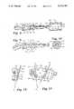
- FIG. 1is a side view of a wrist on which there is arranged a dynamic external fixation device according to the invention.
- FIG. 2is a plan view of the assembly in FIG. 1.
- FIG. 3is a side view of the device in FIG. 1, from the opposite side, showing the maximum extent of the movement permitted.
- FIG. 4is a longitudinal section of the elements in FIG. 3.
- FIG. 5is a cross-section along V--V in FIG. 4, showing the locking of the angular adjustment of the front part.
- FIG. 6is a cross-section along VI--VI in FIG. 4, showing the components constituting the angular adjustment of the rear part.
- FIG. 7is a cross-section along VII--VII in FIG. 4, on a larger scale, showing the guide elements of an arc-shaped slide.
- FIG. 8shows in detail the components constituting the angular adjustment of the front part, seen from above in the lower half of the drawing and in section in the upper part.
- FIG. 9is a view similar to that in FIG. 8, the components being seen from the side in the lower half of the drawing and in section in the upper part.
- FIG. 10is a cross-section along X--X in FIG. 9.
- FIG. 11is a side view of a removable device for guiding the targeting needles.
- FIG. 12is a cross-section along XII--XII in FIG. 11.
- the dynamic external fixation deviceconsists of an articulated joint 10 arranged between an adjustment device 20 and a device 30 permitting play.
- the devices 20 and 30are integral, respectively, with a rear assembly 40 and a front assembly 50 for fixation of pins 60 and 70 inserted in the bones on either side of an articulation 80. Needles 90, integral with the articulated joint 10, make it possible to target the central point of the articulation 80.
- the rear and front assemblies 40 and 50consist, in a conventional manner, of pin-holders 41 and 51, respectively, which can be oriented relative to a positioning and locking flange 42, 52 on a fixation rod 43, 53 integral, respectively, with the devices 20 and 30.
- the groups of pins 60 and 70are inserted in the radius 82 and in the metacarpus 83 of the index finger 84.
- the fixation devices 40 and 50are mounted on the pins and the fixation rods 43 and 53, and the articulated joint 10 is positioned by virtue of the needles 90 making it possible to target the axis of the articulation 80. It is by acting on the assemblies 40 and 50 that the articulated joint 10 can be displaced according to the arrows A and B in FIG. 1.
- the joint 10can also be positioned angularly in accordance with the arrow C, that is to say transversely relative to the longitudinal axis of the apparatus.
- the articulated joint 10is represented as seen from the side. It consists of a casing 11 in two parts 111 and 112 pressed one against the other by means of screws 12 with heads countersunk in the casing.
- a screw 13makes it possible to angularly lock the device 30 permitting the assembly play after positioning it relative to the articulated joint 10 according to the arrow D.
- the half 111 of the casingcomprises an arc-shaped opening 14, centered on the axis 0 of the articulation, and also a scale 15 graduated in degrees.
- the opening 14comprises a stop screw 16, integral with a movable rider which will be described later. It will be noticed that the screws 13 and 16 all have the same hexagonal head, so that the adjustments can be carried out with a single tool.
- the arc-shaped slide 21which is integral with the device 20 and which has a transverse stud 22 intended to abut, on the one hand, against the front edge of the opening 14 and, on the other hand, against the movable rider integral with the stop screw 16.
- the half 112 of the casingadditionally comprises two passages for the target needles 91 and 92 used to center the assembly on the 0 axis of the articulation, as will be seen hereinafter.
- the articulated jointhas been shown in its rest position in full lines and in its position of maximum flexion in broken lines.
- the rod 43forms an angle a of about 10° relative to the axis of the device 20 in order to better follow the configuration of the rest position of the wrist.
- the device 20 for transverse adjustmentconsists of a threaded cylindrical body 23 arranged on the arc-shaped slide 21, which has externally a central opening 24.
- the rear fixation rod 43can be displaced axially in the central opening 24 of the cylindrical body 23 according to the arrow E, with the aid of knurled nuts 25 and 26 arranged on either side of the spur 44 at the end of the rod 43.
- each half 111 and 112 of the casing 11comprises a series of clearances, namely:
- One of the halves 111 or 112 of the casingadditionally comprises a tapped opening leading into a clearance 179, which can be seen in FIG. 5, and into which there is screwed the screw 13 permitting angular positioning of the device 30.
- the screw 13cooperates with a shoe 18 arranged in the clearance 179.
- One of the faces of the shoe 18comprises a cylindrical clearance of a dimension corresponding to the inner rod 31.
- FIG. 7shows the halves 111 and 112 constituting the casing 11 of the articulated joint, and one of the connecting screws 12. It also shows the screw 13 for angular positioning and the stop screw 16 whose head bears on a washer 161 and which is integral with a movable rider 162 arranged inside the arc-shaped opening 14.
- the movable rider 162serves as a stop for the transverse stud 22 of the arc-shaped slide 21.
- the particular shape of the cross-section of the arc-shaped slide 21will be noted, the latter comprising two shoulders 211 and 212 of conical cross-section intended to cooperate with roller bearing assemblies 19. It will be noted that the roller bearing assemblies 191 intended to cooperate with the arc-shaped shoulder 211 differ from the roller bearing assemblies 192 intended to cooperate with the arc-shaped shoulder 212.
- Each roller bearing assembly 191comprises a roller 193 comprising a channel 194 of a shape corresponding to the arc-shaped shoulder 211.
- the faces of the roller 193comprise clearances 195 intended to receive ball-bearings 196 integral with a central shaft 197.
- the roller bearing assembly 192additionally comprises bearings 198 arranged in the openings 175 and 177 formed in the walls 111 and 112.
- the bearings 198are surrounded by an elastomeric seal 199.
- this sealmay be replaced by a series of 0-rings. The purpose of introducing an elastomeric material is to establish a slight pre-stressing permitting elimination of play.
- the inner rod 31can be seen along with its head 311 intended to hold the assembly relative to the casing 11.
- the rod 31additionally comprises a hollow 312, a shoulder 313 and finishes with a cylindrical part 314.
- This part 314comprises a truncated central opening 315 and two opposite lateral clearances 316 (shown in FIGS. 9 and 10) constituting a retention collar 317 intended to provide the connection to the fixation rod 53.
- the fixation rod 53comprises a threaded shoulder 531 and ends with a truncated end 532 of a shape corresponding to that of the central opening 315 of the inner rod 31.
- the end 532receives a retention pin 533.
- a spring 34(shown partially in broken lines in the drawing) is arranged between the shoulders 531 and 313 and is intended to distance the rods 31 and 53 from one another.
- a sleeve 32is intended to cover the assembly described and comprises, at one end, a tapping 321 intended to cooperate with the threaded shoulder 531 and, at the other end, an inner edge 322 intended to cooperate with the shoulder 313 in order to provide for the compression of the spring 34, this edge delimiting a central opening 323 providing for the passage of the inner rod 31.
- a silicon seal 534will advantageously be added as an extension of the shoulder 531, which provides for a braking function in order to prevent untimely loosening of the sleeve 32.
- FIGS. 11 and 12show a variant for positioning the targeting needles 91 and 92 by means of a spring plate 93.
- the plate 93comprises two branches 931 and 932 twice folded 90° inwards in such a way that their sides 933 and 934 match the shape of the half of the casing 11 and their ends come into engagement in two plane clearances 174 described with reference to FIG. 4.
- the plate 93comprises two lateral arms 935, the opposite edges of which comprise oblique tongues 936 to 939 having an opening for the passage of the needles 91 and 92.
- the plate 93By virtue of the elasticity of the plate 93, it is possible to position it easily on the casing 11 by deformation of the sides 933 and 934 during introduction of the terminal claws of the branches 931 and 932 into the clearances 174.
- the oblique tongues 936 and 937are pressed towards each other in order to permit the positioning of the targeting needle 91, in the same way as the tongues 938 and 939 are pressed in order to permit the passage of the needle 92.
- the majority of the constituents of the fixation device describedare made of stainless steel, only the casing 10 and the arc-shaped slide being of light alloy, in order to reduce the weight of the assembly.
- the arc-shaped segment 21is provided with its stop 22 and is made integral, by the pin 27, with the threaded cylindrical body 23 which receives the fixation rod 43, fixed by means of the knurled nuts 25 and 26.
- the inner rod 31 of the device 30 and the fixation rod 53are connected by inserting the retention pin 533 after positioning of the spring 34.
- the sleeve 32is then placed over the assembly.
- the ends of the pin 533can be displaced freely in the opposite lateral clearances 316 of the rod 31, and the resulting movement of the sleeve 32 relative to the rod 31 is made possible since its inner edge 322 can be displaced in the hollow 312. It will also be noted that, in addition to the relative articulation of the rods 31 and 53, the proposed construction permits a slight pivoting of the rod 53 relative to the rod 31, a pivoting which is limited as soon as the ends of the retention pin 533 abut on the edges of the clearances 316. As the sleeve 32 is screwed on the threaded shoulder 531, so the relative movement between the rods 31 and 53 decreases.
- the silicon seal 534serves as a brake on the movement of the sleeve 32, in order to prevent its untimely displacement.
- the devices 20 and 30are positioned in the casing 11.
- the arc-shaped segment 21is arranged between the roller bearing assemblies 19 in such a way that the stop 22 projects into the opening 14 between the screw 16 and the front part of the opening.
- the head 311 for retaining the rod 31is arranged in the hollow 172, and the shoe 18 is arranged in its clearance 179.
- the halves 111 and 112 of the casingare then connected by means of screws 12. Provision can be made for covers to be arranged on the heads of the screws 12 in order to prevent the practitioner from actuating them inadvertently.
- the deviceis then ready to be used. At the moment of its positioning, the device is locked in the following manner:
- the inner rod 31is locked angularly in the plane of the apparatus by means of the screw 13 bearing on the shoe 18,
- the nuts 25 and 26are tightened on both sides of the spur 44, which is arranged longitudinally and angularly in a middle position.
- the practitionerinserts the pins 60 and 70 into the bones, preferably at an angle of about 45° relative to the plane of the hand, then he positions the assemblies 40 and 50 for fixation of the pins.
- the targeting needles 91 and 92are then added, and the adjustment of the flanges 42 and 52 permits positioning of the articulated fixation device according to the arrows A and B in FIG. 1, so that the axis of the rotating components corresponds to the axis of the articulation. This adjustment takes place while monitoring the position of the bones by X-ray.
- the targeting needles 91 and 92are removed, as is the plate 93 in the case where use is made of the variant with a removable plate rather than needles passing through openings in the casing.
- the practitionerBy moving the patient's hand, after temporarily displacing the screw 16 and its rider 162 in the arc-shaped opening 14, the practitioner achieves automatic positioning of the articulated joint in the transverse plane, then he locks the assembly by means of the screw 13 and the knurled nuts 25 and 26. It should be noted that the latter permit a slight tension to be applied at the level of the fractured bone, in order to achieve decompression of the fracture.
- the positioningis thus particularly simplified with the type of fixation device described here, since the adjustment in the plane of the arrows A and B in FIG. 1 is independent of the transverse adjustment according to the arrow C in FIG. 2.
- fixation devicesit was necessary to act on the positioning flanges 42 and 52, and there was consequently a risk of disturbing the assembly when a transverse correction was effected.
- the assemblyremains locked for about 15 days in order for osseous consolidation to begin. Then the screws 16 and its rider 162 are progressively displaced so as to reach, in a few weeks, the maximum flexion movement shown in FIG. 3.
- the sleeve 32which makes it possible to give the device 30 play, can be gradually loosened. The practitioner will carry out this operation depending on the particular anatomy of each patient so that the latter can perform without hindrance the flexion movement permitted by the articulated joint.
Landscapes
- Health & Medical Sciences (AREA)
- Orthopedic Medicine & Surgery (AREA)
- Life Sciences & Earth Sciences (AREA)
- General Health & Medical Sciences (AREA)
- Surgery (AREA)
- Engineering & Computer Science (AREA)
- Biomedical Technology (AREA)
- Heart & Thoracic Surgery (AREA)
- Veterinary Medicine (AREA)
- Public Health (AREA)
- Animal Behavior & Ethology (AREA)
- Transplantation (AREA)
- Molecular Biology (AREA)
- Medical Informatics (AREA)
- Nuclear Medicine, Radiotherapy & Molecular Imaging (AREA)
- Cardiology (AREA)
- Oral & Maxillofacial Surgery (AREA)
- Vascular Medicine (AREA)
- Surgical Instruments (AREA)
- Prostheses (AREA)
- Orthopedics, Nursing, And Contraception (AREA)
- Sealing Devices (AREA)
- Flanged Joints, Insulating Joints, And Other Joints (AREA)
- Magnetic Heads (AREA)
- Clamps And Clips (AREA)
- Machine Tool Sensing Apparatuses (AREA)
- Magnetic Resonance Imaging Apparatus (AREA)
- Accommodation For Nursing Or Treatment Tables (AREA)
Abstract
Description
Claims (18)
Applications Claiming Priority (1)
| Application Number | Priority Date | Filing Date | Title |
|---|---|---|---|
| CH3060/89ACH680769A5 (en) | 1989-08-23 | 1989-08-23 |
Publications (1)
| Publication Number | Publication Date |
|---|---|
| US5122140Atrue US5122140A (en) | 1992-06-16 |
Family
ID=4247718
Family Applications (1)
| Application Number | Title | Priority Date | Filing Date |
|---|---|---|---|
| US07/572,523Expired - LifetimeUS5122140A (en) | 1989-08-23 | 1990-08-23 | Dynamic external fixation device |
Country Status (11)
| Country | Link |
|---|---|
| US (1) | US5122140A (en) |
| EP (1) | EP0414633B1 (en) |
| JP (1) | JP2511564B2 (en) |
| KR (1) | KR920010760B1 (en) |
| AT (1) | ATE125439T1 (en) |
| AU (1) | AU631450B2 (en) |
| CA (1) | CA2023672C (en) |
| CH (1) | CH680769A5 (en) |
| DE (3) | DE9010886U1 (en) |
| ES (1) | ES2075185T3 (en) |
| IE (1) | IE903033A1 (en) |
Cited By (61)
| Publication number | Priority date | Publication date | Assignee | Title |
|---|---|---|---|---|
| WO1994010947A1 (en)* | 1992-11-10 | 1994-05-26 | Innovative Orthopaedics Manufacturing, Inc. | Dynamic external fixator for the wrist |
| US5358504A (en)* | 1993-05-05 | 1994-10-25 | Smith & Nephew Richards, Inc. | Fixation brace with focal hinge |
| US5397322A (en)* | 1990-08-03 | 1995-03-14 | Jaquet Orthopedie S.A. | Manipulator for external bone fixation devices |
| US5429637A (en)* | 1991-11-08 | 1995-07-04 | Hardy; Jean M. | External modular fixator for immobilization of a fracture |
| US5578038A (en)* | 1992-06-18 | 1996-11-26 | Slocum; D. Barclay | Jig for use in osteotomies |
| US5681313A (en)* | 1995-02-06 | 1997-10-28 | Karl Leibinger Medizintechnik Gmbh & Co. Kg | Device for the extension of bones |
| US5738684A (en)* | 1995-05-01 | 1998-04-14 | Keele University | External bone fixator |
| US5941877A (en)* | 1998-01-14 | 1999-08-24 | The Board Of Regents Of The University Of Texas System | Hand external fixation and joint mobilization and distraction device |
| WO2000053109A1 (en) | 1999-03-10 | 2000-09-14 | Synthes Ag Chur | External fixation device for bone |
| US6159210A (en)* | 1997-01-14 | 2000-12-12 | Research Corporation Technologies, Inc. | Bone fixation pin with rotary cutting tip |
| US6162223A (en)* | 1999-04-09 | 2000-12-19 | Smith & Nephew, Inc. | Dynamic wrist fixation apparatus for early joint motion in distal radius fractures |
| US6409729B1 (en) | 1998-05-19 | 2002-06-25 | Synthes (Usa) | Clamp assembly for an external fixation system |
| US6428540B1 (en) | 1996-11-13 | 2002-08-06 | Synthes (U.S.A.) | Device for repositioning fractured bone fragments |
| FR2829684A1 (en)* | 2001-09-14 | 2003-03-21 | Obl | EXTERNAL BONE DISTRACTOR |
| US20030069580A1 (en)* | 2001-10-09 | 2003-04-10 | Langmaid Michael N. | Adjustable fixator |
| US6572616B2 (en) | 2000-05-24 | 2003-06-03 | Fixus B.V. | Fixing device for orthopedic applications |
| US20030153910A1 (en)* | 2002-02-11 | 2003-08-14 | Pioneer Laboratories, Inc. | External fixation apparatus and method |
| US6652524B1 (en)* | 2002-05-30 | 2003-11-25 | Millennium Medical Technologies, Inc. | Fixator with outrigger |
| US20040044344A1 (en)* | 2000-02-02 | 2004-03-04 | Winquist Robert A. | Adjustable bone stabilizing frame system |
| US20040097944A1 (en)* | 2002-07-30 | 2004-05-20 | Koman L. Andrew | Fixation device and method for treating contractures and other orthopedic indications |
| US6746448B2 (en) | 2002-05-30 | 2004-06-08 | Millennium Medical Technologies, Inc. | Outrigger for bone fixator |
| US20040133200A1 (en)* | 2002-11-15 | 2004-07-08 | Ruch David S. | Apparatus and method for maintaining bones in a healing position |
| US20040181221A1 (en)* | 2003-03-12 | 2004-09-16 | Huebner Randall J. | External fixator |
| US20040249375A1 (en)* | 2003-06-03 | 2004-12-09 | The John M. Agee Trust | External fixator for colles' fracture |
| US6852113B2 (en) | 2001-12-14 | 2005-02-08 | Orthopaedic Designs, Llc | Internal osteotomy fixation device |
| WO2006013670A1 (en)* | 2004-08-03 | 2006-02-09 | Yoshino Industry, Co., Ltd. | Medical external fixation device |
| US20060085076A1 (en)* | 2004-10-15 | 2006-04-20 | Manoj Krishna | Posterior spinal arthroplasty-development of a new posteriorly inserted artificial disc and an artificial facet joint |
| US20060229603A1 (en)* | 2005-03-18 | 2006-10-12 | Olsen Ron A | Adjustable splint for osteosynthesis with modular joint |
| US20060229605A1 (en)* | 2005-03-18 | 2006-10-12 | Olsen Ron A | Adjustable splint for osteosynthesis with incrementing assembly for adjustment in predetermined increments |
| US20060241590A1 (en)* | 2005-04-25 | 2006-10-26 | Jean-Noel Bordeaux | Outrigger with locking mechanism |
| WO2006115395A1 (en)* | 2005-04-26 | 2006-11-02 | Flecares B.V. | Hinged splint device and method for adjusting such a splint device |
| US20060265074A1 (en)* | 2004-10-21 | 2006-11-23 | Manoj Krishna | Posterior spinal arthroplasty-development of a new posteriorly inserted artificial disc, a new anteriorly inserted artifical disc and an artificial facet joint |
| US20070162028A1 (en)* | 2005-12-09 | 2007-07-12 | Jesse Jackson | Cannulated screw |
| US20080021451A1 (en)* | 2006-04-20 | 2008-01-24 | Millennium Medical Technologies, Inc. | External Fixator |
| US20080154307A1 (en)* | 2004-08-09 | 2008-06-26 | Dennis Colleran | System and method for dynamic skeletal stabilization |
| US20080200952A1 (en)* | 2005-06-13 | 2008-08-21 | Intelligent Orthopaedics Ltd | Bone Fixator |
| US20090036891A1 (en)* | 2005-08-09 | 2009-02-05 | Zimmer Technology, Inc. | Orthopaedic fixation clamp and method |
| US20090093847A1 (en)* | 2007-10-09 | 2009-04-09 | Warsaw Orthopedic, Inc. | Variable angle rod connectors and the methods of use |
| US20090125068A1 (en)* | 2003-02-28 | 2009-05-14 | Estrada Jr Hector Mark | Apparatus for Dynamic External Fixation of Distal Radius and Wrist Fractures |
| US20090248026A1 (en)* | 2001-03-28 | 2009-10-01 | Moximed, Inc. | Bone fixated, articulated joint load control device |
| US20100234844A1 (en)* | 2009-03-10 | 2010-09-16 | Stryker Trauma Sa | Exernal fixation system |
| US20110040331A1 (en)* | 2009-05-20 | 2011-02-17 | Jose Fernandez | Posterior stabilizer |
| US20110082458A1 (en)* | 2009-10-05 | 2011-04-07 | Stryker Trauma Sa | Dynamic External Fixator And Methods For Use |
| US20120323287A1 (en)* | 2011-06-17 | 2012-12-20 | Biomet Manufacturing, Corp. | Implant to stress bone to alter morphology |
| ITBO20120576A1 (en)* | 2012-10-23 | 2014-04-24 | Citieffe Srl | ARTICULATED JOINT FOR ORTHOPEDIC DEVICES |
| US8758343B2 (en) | 2005-04-27 | 2014-06-24 | DePuy Synthes Products, LLC | Bone fixation apparatus |
| US8777946B2 (en) | 2009-10-05 | 2014-07-15 | Aalto University Foundation | Anatomically customized and mobilizing external support, method for manufacture |
| US8834467B2 (en) | 2010-08-11 | 2014-09-16 | Stryker Trauma Sa | External fixator system |
| US8945128B2 (en) | 2010-08-11 | 2015-02-03 | Stryker Trauma Sa | External fixator system |
| US9101398B2 (en) | 2012-08-23 | 2015-08-11 | Stryker Trauma Sa | Bone transport external fixation frame |
| CN104837422A (en)* | 2013-01-21 | 2015-08-12 | 泰克里斯公司 | External fixing device, for treating bone fractures |
| US9155561B2 (en) | 2013-03-06 | 2015-10-13 | Stryker Trauma Sa | Mini-rail external fixator |
| USRE46077E1 (en)* | 2008-09-11 | 2016-07-26 | Orthofix S.R.L. | Support orthopaedic device for a knee joint |
| US9480519B2 (en) | 2012-10-04 | 2016-11-01 | Loubert S. Suddaby | Apparatus for aligning a spine using deployable bone anchors and method for the same |
| US9737336B2 (en) | 2009-10-05 | 2017-08-22 | Aalto University Foundation | Anatomically personalized and mobilizing external support and method for controlling a path of an external auxiliary frame |
| US9962188B2 (en) | 2013-10-29 | 2018-05-08 | Cardinal Health 247. Inc. | External fixation system and methods of use |
| US9968379B2 (en) | 2012-10-04 | 2018-05-15 | Loubert S. Suddaby | Subcutaneous implantable device for gradually aligning a spine and subcutaneous implantable device for gradually lengthening a bone |
| US10022153B2 (en) | 2012-10-04 | 2018-07-17 | Loubert S. Suddaby | Percutaneous method for aligning a spine using deployable bone anchors |
| US10531896B2 (en) | 2015-08-10 | 2020-01-14 | Stryker European Holdings I, Llc | Distraction tube with wire clamp |
| US11141196B2 (en) | 2010-08-11 | 2021-10-12 | Stryker European Operations Holdings Llc | External fixator system |
| US11653951B2 (en)* | 2018-11-06 | 2023-05-23 | Ali Moradi | External orthopedic fixation device |
Families Citing this family (9)
| Publication number | Priority date | Publication date | Assignee | Title |
|---|---|---|---|---|
| IT1259765B (en)* | 1992-04-30 | 1996-03-26 | Lima Spa | EXTERNAL FIXER FOR WRIST WITH ADJUSTABLE CAM JOINT |
| FR2728454B1 (en)* | 1994-12-21 | 1997-06-13 | Razian Hassan | IMPLANTABLE INTERVERTEBRAL CONNECTION DEVICE AND DISTRACTION ANCILLARY FOR IMPLANTATION OF SUCH A DEVICE |
| IT1278858B1 (en)* | 1995-09-20 | 1997-11-28 | Orthofix Srl | INSTRUMENTS FOR THE TREATMENT OF ARTICULAR FRACTURES OF THE ANKLE |
| KR100363661B1 (en)* | 2000-03-29 | 2002-12-05 | 유앤아이 주식회사 | Outside the body fixing device for bone fracture theraphy |
| GB2425960A (en)* | 2005-05-12 | 2006-11-15 | Ali Bajwa | Adjustable splint |
| AU2012225496B2 (en) | 2011-03-07 | 2016-09-22 | Conventus Orthopaedics, Inc. | Apparatus and methods for bone repair preparation |
| TWI528954B (en)* | 2013-12-02 | 2016-04-11 | 財團法人金屬工業研究發展中心 | Dynamic external fixation device |
| DE102018103566A1 (en)* | 2018-02-16 | 2019-08-22 | Universität Paderborn | External fixator |
| WO2020092049A1 (en)* | 2018-10-30 | 2020-05-07 | Smith & Nephew, Inc. | External fixation strut |
Citations (7)
| Publication number | Priority date | Publication date | Assignee | Title |
|---|---|---|---|---|
| US4273116A (en)* | 1978-06-27 | 1981-06-16 | Claude Chiquet | Device for external fixation of bone fragments |
| US4488542A (en)* | 1981-11-27 | 1984-12-18 | Per Helland | External setting and correction device for the treatment of bone fractures |
| US4628919A (en)* | 1983-09-09 | 1986-12-16 | Clyburn Terry | Dynamic external fixator and method of use |
| US4628922A (en)* | 1984-09-28 | 1986-12-16 | University College London | Fracture reduction apparatus |
| US4848368A (en)* | 1988-04-25 | 1989-07-18 | Kronner Richard F | Universal external fixation frame assembly |
| US4988349A (en)* | 1987-01-21 | 1991-01-29 | Orthofix S.R.L. | Device for osteosynthesis |
| US5019077A (en)* | 1989-03-17 | 1991-05-28 | Orthofix S.R.L. | External splint |
Family Cites Families (6)
| Publication number | Priority date | Publication date | Assignee | Title |
|---|---|---|---|---|
| JPS5246429A (en)* | 1975-10-09 | 1977-04-13 | Jeol Ltd | Direct current high voltage power source |
| AU8208582A (en)* | 1981-02-20 | 1982-09-14 | Ace Orthopedic Manufacturing Inc. | Colles fracture fixature device |
| JPS5819296A (en)* | 1981-07-24 | 1983-02-04 | シャープ株式会社 | Clothes dryer control device |
| GB8504539D0 (en)* | 1985-02-21 | 1985-03-27 | Thackray C F Ltd | Bone fixation system |
| US4919119A (en)* | 1986-05-20 | 1990-04-24 | Jaquet Orthopedie, S.A. | External dynamic bone fixation device |
| ES2069533T3 (en)* | 1986-08-11 | 1995-05-16 | Jaquet Orthopedie | EXTERNAL BIOCOMPRESSION FIXER FOR OSTEOSYNTHESIS. |
- 1989
- 1989-08-23CHCH3060/89Apatent/CH680769A5/frnot_activeIP Right Cessation
- 1990
- 1990-07-21DEDE9010886Upatent/DE9010886U1/ennot_activeExpired - Lifetime
- 1990-08-08DEDE69021150Tpatent/DE69021150T2/ennot_activeExpired - Lifetime
- 1990-08-08ESES90810599Tpatent/ES2075185T3/ennot_activeExpired - Lifetime
- 1990-08-08EPEP90810599Apatent/EP0414633B1/ennot_activeExpired - Lifetime
- 1990-08-08ATAT90810599Tpatent/ATE125439T1/ennot_activeIP Right Cessation
- 1990-08-21CACA002023672Apatent/CA2023672C/ennot_activeExpired - Fee Related
- 1990-08-22DEDE9012098Upatent/DE9012098U1/ennot_activeExpired - Lifetime
- 1990-08-22IEIE303390Apatent/IE903033A1/enunknown
- 1990-08-22AUAU61233/90Apatent/AU631450B2/ennot_activeCeased
- 1990-08-22KRKR1019900012939Apatent/KR920010760B1/ennot_activeExpired
- 1990-08-23USUS07/572,523patent/US5122140A/ennot_activeExpired - Lifetime
- 1990-08-23JPJP2222318Apatent/JP2511564B2/ennot_activeExpired - Lifetime
Patent Citations (7)
| Publication number | Priority date | Publication date | Assignee | Title |
|---|---|---|---|---|
| US4273116A (en)* | 1978-06-27 | 1981-06-16 | Claude Chiquet | Device for external fixation of bone fragments |
| US4488542A (en)* | 1981-11-27 | 1984-12-18 | Per Helland | External setting and correction device for the treatment of bone fractures |
| US4628919A (en)* | 1983-09-09 | 1986-12-16 | Clyburn Terry | Dynamic external fixator and method of use |
| US4628922A (en)* | 1984-09-28 | 1986-12-16 | University College London | Fracture reduction apparatus |
| US4988349A (en)* | 1987-01-21 | 1991-01-29 | Orthofix S.R.L. | Device for osteosynthesis |
| US4848368A (en)* | 1988-04-25 | 1989-07-18 | Kronner Richard F | Universal external fixation frame assembly |
| US5019077A (en)* | 1989-03-17 | 1991-05-28 | Orthofix S.R.L. | External splint |
Cited By (116)
| Publication number | Priority date | Publication date | Assignee | Title |
|---|---|---|---|---|
| US5397322A (en)* | 1990-08-03 | 1995-03-14 | Jaquet Orthopedie S.A. | Manipulator for external bone fixation devices |
| US5429637A (en)* | 1991-11-08 | 1995-07-04 | Hardy; Jean M. | External modular fixator for immobilization of a fracture |
| US5578038A (en)* | 1992-06-18 | 1996-11-26 | Slocum; D. Barclay | Jig for use in osteotomies |
| US5437667A (en)* | 1992-11-10 | 1995-08-01 | Innovative Orthopaedics, Manufacturing, Inc. | Dynamic external fixator for the wrist |
| WO1994010947A1 (en)* | 1992-11-10 | 1994-05-26 | Innovative Orthopaedics Manufacturing, Inc. | Dynamic external fixator for the wrist |
| US5358504A (en)* | 1993-05-05 | 1994-10-25 | Smith & Nephew Richards, Inc. | Fixation brace with focal hinge |
| US5681313A (en)* | 1995-02-06 | 1997-10-28 | Karl Leibinger Medizintechnik Gmbh & Co. Kg | Device for the extension of bones |
| US5738684A (en)* | 1995-05-01 | 1998-04-14 | Keele University | External bone fixator |
| US6428540B1 (en) | 1996-11-13 | 2002-08-06 | Synthes (U.S.A.) | Device for repositioning fractured bone fragments |
| US6159210A (en)* | 1997-01-14 | 2000-12-12 | Research Corporation Technologies, Inc. | Bone fixation pin with rotary cutting tip |
| US5941877A (en)* | 1998-01-14 | 1999-08-24 | The Board Of Regents Of The University Of Texas System | Hand external fixation and joint mobilization and distraction device |
| US6409729B1 (en) | 1998-05-19 | 2002-06-25 | Synthes (Usa) | Clamp assembly for an external fixation system |
| US6245071B1 (en) | 1999-03-10 | 2001-06-12 | Synthes (U.S.A.) | External fixation device for bone |
| WO2000053109A1 (en) | 1999-03-10 | 2000-09-14 | Synthes Ag Chur | External fixation device for bone |
| US6162223A (en)* | 1999-04-09 | 2000-12-19 | Smith & Nephew, Inc. | Dynamic wrist fixation apparatus for early joint motion in distal radius fractures |
| US8696668B2 (en) | 2000-02-02 | 2014-04-15 | Zimmer, Inc. | Adjustable bone stabilizing frame system |
| US20040044344A1 (en)* | 2000-02-02 | 2004-03-04 | Winquist Robert A. | Adjustable bone stabilizing frame system |
| US20110172665A1 (en)* | 2000-02-02 | 2011-07-14 | Zimmer Technology, Inc. | Adjustable bone stabilizing frame system |
| US7931650B2 (en) | 2000-02-02 | 2011-04-26 | Zimmer Technology, Inc. | Adjustable bone stabilizing frame system |
| US6572616B2 (en) | 2000-05-24 | 2003-06-03 | Fixus B.V. | Fixing device for orthopedic applications |
| US20090248026A1 (en)* | 2001-03-28 | 2009-10-01 | Moximed, Inc. | Bone fixated, articulated joint load control device |
| US9943336B2 (en)* | 2001-03-28 | 2018-04-17 | Moximed, Inc. | Bone fixated, articulated joint load control device |
| US9610103B2 (en) | 2001-03-28 | 2017-04-04 | Moximed, Inc. | Bone fixated, articulated joint load control device |
| US20100145336A1 (en)* | 2001-03-28 | 2010-06-10 | Moximed, Inc. | Bone fixated, articulated joint load control device |
| WO2003024341A1 (en)* | 2001-09-14 | 2003-03-27 | Obl Société Anonyme | External bone distractor |
| FR2829684A1 (en)* | 2001-09-14 | 2003-03-21 | Obl | EXTERNAL BONE DISTRACTOR |
| US8382757B1 (en) | 2001-10-09 | 2013-02-26 | Synthes Usa, Llc | Adjustable fixator |
| US7261713B2 (en) | 2001-10-09 | 2007-08-28 | Synthes (Usa) | Adjustable fixator |
| US20030069580A1 (en)* | 2001-10-09 | 2003-04-10 | Langmaid Michael N. | Adjustable fixator |
| US6852113B2 (en) | 2001-12-14 | 2005-02-08 | Orthopaedic Designs, Llc | Internal osteotomy fixation device |
| US6860883B2 (en) | 2002-02-11 | 2005-03-01 | Pioneer Laboratories, Inc. | External fixation apparatus and method |
| US20030153910A1 (en)* | 2002-02-11 | 2003-08-14 | Pioneer Laboratories, Inc. | External fixation apparatus and method |
| US6652524B1 (en)* | 2002-05-30 | 2003-11-25 | Millennium Medical Technologies, Inc. | Fixator with outrigger |
| US20090099565A1 (en)* | 2002-05-30 | 2009-04-16 | Millennium Medical Technologies, Inc. | Method Of Fracture Fixation |
| US8137347B2 (en) | 2002-05-30 | 2012-03-20 | Millennium Medical Technologies, Inc. | Method of fracture fixation |
| US7479142B2 (en) | 2002-05-30 | 2009-01-20 | Millenium Medical Technologies, Inc. | Method of fracture fixation |
| US6746448B2 (en) | 2002-05-30 | 2004-06-08 | Millennium Medical Technologies, Inc. | Outrigger for bone fixator |
| US20040097944A1 (en)* | 2002-07-30 | 2004-05-20 | Koman L. Andrew | Fixation device and method for treating contractures and other orthopedic indications |
| US20040133200A1 (en)* | 2002-11-15 | 2004-07-08 | Ruch David S. | Apparatus and method for maintaining bones in a healing position |
| US20090125068A1 (en)* | 2003-02-28 | 2009-05-14 | Estrada Jr Hector Mark | Apparatus for Dynamic External Fixation of Distal Radius and Wrist Fractures |
| US20040181221A1 (en)* | 2003-03-12 | 2004-09-16 | Huebner Randall J. | External fixator |
| US7147640B2 (en)* | 2003-03-12 | 2006-12-12 | Acumed Llc | External fixator |
| US7291148B2 (en)* | 2003-06-03 | 2007-11-06 | John M. Agee Trustee Of The John M. Agee Trust | External fixator for Colles' fracture |
| US20040249375A1 (en)* | 2003-06-03 | 2004-12-09 | The John M. Agee Trust | External fixator for colles' fracture |
| WO2006013670A1 (en)* | 2004-08-03 | 2006-02-09 | Yoshino Industry, Co., Ltd. | Medical external fixation device |
| US8038700B2 (en)* | 2004-08-09 | 2011-10-18 | Theken Spine, Llc | System and method for dynamic skeletal stabilization |
| US20080154307A1 (en)* | 2004-08-09 | 2008-06-26 | Dennis Colleran | System and method for dynamic skeletal stabilization |
| US20080033562A1 (en)* | 2004-10-15 | 2008-02-07 | Disc Motion Technologies, Inc. | Posteriorly inserted artificial disc and an artificial facet joint |
| US8852235B2 (en)* | 2004-10-15 | 2014-10-07 | Spinadyne, Inc. | Posteriorly inserted artificial disc and an artificial facet joint |
| US20060085076A1 (en)* | 2004-10-15 | 2006-04-20 | Manoj Krishna | Posterior spinal arthroplasty-development of a new posteriorly inserted artificial disc and an artificial facet joint |
| US20060265074A1 (en)* | 2004-10-21 | 2006-11-23 | Manoj Krishna | Posterior spinal arthroplasty-development of a new posteriorly inserted artificial disc, a new anteriorly inserted artifical disc and an artificial facet joint |
| US8673009B2 (en) | 2004-10-21 | 2014-03-18 | Spinadyne, Inc. | Spinal prosthesis and facet joint prosthesis |
| US8673008B2 (en) | 2004-10-21 | 2014-03-18 | Spinadyne, Inc. | Posterior spinal arthroplasty system |
| US7588571B2 (en) | 2005-03-18 | 2009-09-15 | Ron Anthon Olsen | Adjustable splint for osteosynthesis with modular joint |
| US20060229605A1 (en)* | 2005-03-18 | 2006-10-12 | Olsen Ron A | Adjustable splint for osteosynthesis with incrementing assembly for adjustment in predetermined increments |
| US20060229603A1 (en)* | 2005-03-18 | 2006-10-12 | Olsen Ron A | Adjustable splint for osteosynthesis with modular joint |
| US20060229602A1 (en)* | 2005-03-18 | 2006-10-12 | Olsen Ron A | Adjustable splint for osteosynthesis |
| US7575575B2 (en) | 2005-03-18 | 2009-08-18 | Ron Anthon Olsen | Adjustable splint for osteosynthesis with modular components |
| US20060229604A1 (en)* | 2005-03-18 | 2006-10-12 | Olsen Ron A | Adjustable splint for osteosynthesis with modular components |
| US7507240B2 (en) | 2005-03-18 | 2009-03-24 | Ron Anthon Olsen | Adjustable splint for osteosynthesis |
| US20060241590A1 (en)* | 2005-04-25 | 2006-10-26 | Jean-Noel Bordeaux | Outrigger with locking mechanism |
| US9273715B2 (en) | 2005-04-25 | 2016-03-01 | DePuy Synthes Products, Inc. | Outrigger with locking mechanism |
| US7722609B2 (en) | 2005-04-25 | 2010-05-25 | Synthes Usa, Llc | Outrigger with locking mechanism |
| WO2006115395A1 (en)* | 2005-04-26 | 2006-11-02 | Flecares B.V. | Hinged splint device and method for adjusting such a splint device |
| US8758343B2 (en) | 2005-04-27 | 2014-06-24 | DePuy Synthes Products, LLC | Bone fixation apparatus |
| US20080200952A1 (en)* | 2005-06-13 | 2008-08-21 | Intelligent Orthopaedics Ltd | Bone Fixator |
| US20090036891A1 (en)* | 2005-08-09 | 2009-02-05 | Zimmer Technology, Inc. | Orthopaedic fixation clamp and method |
| US20070162028A1 (en)* | 2005-12-09 | 2007-07-12 | Jesse Jackson | Cannulated screw |
| US7731738B2 (en) | 2005-12-09 | 2010-06-08 | Orthopro, Llc | Cannulated screw |
| US7985221B2 (en) | 2006-04-20 | 2011-07-26 | Millennium Medical Technologies, Inc. | External fixator |
| US20080021451A1 (en)* | 2006-04-20 | 2008-01-24 | Millennium Medical Technologies, Inc. | External Fixator |
| US8147519B2 (en) | 2007-10-09 | 2012-04-03 | Warsaw Orthopedic, Inc. | Variable angle rod connectors and the methods of use |
| US20090093847A1 (en)* | 2007-10-09 | 2009-04-09 | Warsaw Orthopedic, Inc. | Variable angle rod connectors and the methods of use |
| USRE46077E1 (en)* | 2008-09-11 | 2016-07-26 | Orthofix S.R.L. | Support orthopaedic device for a knee joint |
| US20100234844A1 (en)* | 2009-03-10 | 2010-09-16 | Stryker Trauma Sa | Exernal fixation system |
| US9044271B2 (en) | 2009-03-10 | 2015-06-02 | Stryker Trauma Sa | External fixation system |
| US8333766B2 (en) | 2009-03-10 | 2012-12-18 | Stryker Trauma Sa | External fixation system |
| US20110040331A1 (en)* | 2009-05-20 | 2011-02-17 | Jose Fernandez | Posterior stabilizer |
| US9351763B2 (en) | 2009-10-05 | 2016-05-31 | Stryker European Holdings I, Llc | Dynamic external fixator and methods for use |
| US8777946B2 (en) | 2009-10-05 | 2014-07-15 | Aalto University Foundation | Anatomically customized and mobilizing external support, method for manufacture |
| US10149701B2 (en) | 2009-10-05 | 2018-12-11 | Stryker European Holdings I, Llc | Dynamic external fixator and methods for use |
| US8858555B2 (en) | 2009-10-05 | 2014-10-14 | Stryker Trauma Sa | Dynamic external fixator and methods for use |
| US8906020B2 (en) | 2009-10-05 | 2014-12-09 | Stryker Trauma Sa | Dynamic external fixator and methods for use |
| US9737336B2 (en) | 2009-10-05 | 2017-08-22 | Aalto University Foundation | Anatomically personalized and mobilizing external support and method for controlling a path of an external auxiliary frame |
| US20110082458A1 (en)* | 2009-10-05 | 2011-04-07 | Stryker Trauma Sa | Dynamic External Fixator And Methods For Use |
| US10080585B2 (en) | 2010-08-11 | 2018-09-25 | Stryker European Holdings I, Llc | External fixator system |
| US10285734B2 (en) | 2010-08-11 | 2019-05-14 | Stryker European Holdings I, Llc | External fixator system |
| US12035944B2 (en) | 2010-08-11 | 2024-07-16 | Stryker European Operations Holdings Llc | External fixator system |
| US11141196B2 (en) | 2010-08-11 | 2021-10-12 | Stryker European Operations Holdings Llc | External fixator system |
| US10376285B2 (en) | 2010-08-11 | 2019-08-13 | Stryker European Holdings I, Llc | External fixator system |
| US9220533B2 (en) | 2010-08-11 | 2015-12-29 | Stryker Trauma Sa | External fixator system |
| US8834467B2 (en) | 2010-08-11 | 2014-09-16 | Stryker Trauma Sa | External fixator system |
| US9839445B2 (en) | 2010-08-11 | 2017-12-12 | Stryker European Holdings I, Llc | External fixator system |
| US8945128B2 (en) | 2010-08-11 | 2015-02-03 | Stryker Trauma Sa | External fixator system |
| US9730730B2 (en) | 2010-08-11 | 2017-08-15 | Stryker European Holdings I, Llc | External fixator system |
| US9717527B2 (en) | 2010-08-11 | 2017-08-01 | Stryker European Holdings I, Llc | External fixator system |
| US9439696B2 (en)* | 2011-06-17 | 2016-09-13 | Biomet Manufacturing, Llc | Implant to stress bone to alter morphology |
| US20120323287A1 (en)* | 2011-06-17 | 2012-12-20 | Biomet Manufacturing, Corp. | Implant to stress bone to alter morphology |
| US11090086B2 (en) | 2012-08-23 | 2021-08-17 | Stryker European Operations Holdings Llc | Bone transport external fixation frame |
| US10405888B2 (en) | 2012-08-23 | 2019-09-10 | Stryker European Holdings I, Llc | Bone transport external fixation frame |
| US11744616B2 (en) | 2012-08-23 | 2023-09-05 | Stryker European Operations Holdings Llc | Bone transport external fixation frame |
| US9101398B2 (en) | 2012-08-23 | 2015-08-11 | Stryker Trauma Sa | Bone transport external fixation frame |
| US9820775B2 (en) | 2012-08-23 | 2017-11-21 | Styker European Holdings I, LLC | Bone transport external fixation frame |
| US9480519B2 (en) | 2012-10-04 | 2016-11-01 | Loubert S. Suddaby | Apparatus for aligning a spine using deployable bone anchors and method for the same |
| US9968379B2 (en) | 2012-10-04 | 2018-05-15 | Loubert S. Suddaby | Subcutaneous implantable device for gradually aligning a spine and subcutaneous implantable device for gradually lengthening a bone |
| US10022153B2 (en) | 2012-10-04 | 2018-07-17 | Loubert S. Suddaby | Percutaneous method for aligning a spine using deployable bone anchors |
| ITBO20120576A1 (en)* | 2012-10-23 | 2014-04-24 | Citieffe Srl | ARTICULATED JOINT FOR ORTHOPEDIC DEVICES |
| WO2014064589A1 (en)* | 2012-10-23 | 2014-05-01 | Citieffe S.R.L. | Articulated joint for orthopaedic devices |
| CN104837422A (en)* | 2013-01-21 | 2015-08-12 | 泰克里斯公司 | External fixing device, for treating bone fractures |
| US9750538B2 (en)* | 2013-01-21 | 2017-09-05 | Tecres S.P.A. | External fixing device, for treating bone fractures |
| US20160022315A1 (en)* | 2013-01-21 | 2016-01-28 | Tecres S.P.A. | External fixing device, for treating bone fractures |
| US9155561B2 (en) | 2013-03-06 | 2015-10-13 | Stryker Trauma Sa | Mini-rail external fixator |
| US9622781B2 (en) | 2013-03-06 | 2017-04-18 | Stryker European Holdings I, Llc | Mini-rail external fixator |
| US9962188B2 (en) | 2013-10-29 | 2018-05-08 | Cardinal Health 247. Inc. | External fixation system and methods of use |
| US10531896B2 (en) | 2015-08-10 | 2020-01-14 | Stryker European Holdings I, Llc | Distraction tube with wire clamp |
| US11653951B2 (en)* | 2018-11-06 | 2023-05-23 | Ali Moradi | External orthopedic fixation device |
Also Published As
| Publication number | Publication date |
|---|---|
| DE69021150T2 (en) | 1996-01-18 |
| ES2075185T3 (en) | 1995-10-01 |
| KR920010760B1 (en) | 1992-12-17 |
| AU6123390A (en) | 1991-07-04 |
| DE9012098U1 (en) | 1991-02-21 |
| DE69021150D1 (en) | 1995-08-31 |
| DE9010886U1 (en) | 1990-09-27 |
| AU631450B2 (en) | 1992-11-26 |
| JPH0392151A (en) | 1991-04-17 |
| EP0414633B1 (en) | 1995-07-26 |
| CA2023672A1 (en) | 1991-02-24 |
| EP0414633A1 (en) | 1991-02-27 |
| ATE125439T1 (en) | 1995-08-15 |
| CH680769A5 (en) | 1992-11-13 |
| IE903033A1 (en) | 1991-02-27 |
| CA2023672C (en) | 1994-08-02 |
| KR910004163A (en) | 1991-03-28 |
| JP2511564B2 (en) | 1996-06-26 |
Similar Documents
| Publication | Publication Date | Title |
|---|---|---|
| US5122140A (en) | Dynamic external fixation device | |
| EP0248138B1 (en) | External dynamic bone fixation device | |
| US12295634B2 (en) | Bone fixation system, assembly, implants, devices, alignment guides, and methods of use | |
| US5545162A (en) | External fixator for repairing fractures of distal radius and wrist | |
| US6171309B1 (en) | External fixator for repairing fractures of distal radius and wrist | |
| US6283969B1 (en) | Bone plating system | |
| US5658283A (en) | External fixator for repairing fractures | |
| US4987892A (en) | Spinal fixation device | |
| EP1463466B1 (en) | Accessory for implanting a hip endoprosthesis | |
| US9308037B2 (en) | Ankle fusion device, instrumentation and methods | |
| US5108398A (en) | Orthopaedic knee fusion apparatus | |
| US4308863A (en) | External fixation device | |
| US5683393A (en) | Bidirectional rod-hook locking mechanism | |
| US2765787A (en) | Hip arthroplasty with flexible securing means | |
| US4895141A (en) | Unilateral external fixation device | |
| US4865025A (en) | Drill guide aiming device for medullary rods | |
| US5162039A (en) | Distraction and reduction device | |
| US20070270846A1 (en) | Fixture, intramedullary nail kit and method of presetting a nail assembly | |
| US20070233102A1 (en) | Variable angle fixture, kit and method of presetting a nail assembly | |
| US20070233100A1 (en) | Variable angle intramedullary nail | |
| US20070233101A1 (en) | Variable angle intramedullary nail, assembly and method | |
| US20250241695A1 (en) | Guided systems and methods for implementing fasteners into tissue | |
| AU746310B2 (en) | Ancillary equipment for preparing the setting of a knee prosthesis | |
| CN87211460U (en) | Immobilization and guiding instrument for intertuberous femoral neck fracture | |
| FI89134C (en) | UNDERSTANDING |
Legal Events
| Date | Code | Title | Description |
|---|---|---|---|
| FEPP | Fee payment procedure | Free format text:PAYOR NUMBER ASSIGNED (ORIGINAL EVENT CODE: ASPN); ENTITY STATUS OF PATENT OWNER: LARGE ENTITY | |
| AS | Assignment | Owner name:JAQUET ORTHOPEDIE S.A., 5 CHEMIN DES AULX, 1228 PL Free format text:ASSIGNMENT OF ASSIGNORS INTEREST.;ASSIGNORS:ASCHE, GERNOT;WAGENKNECHT, MARCEL H.;REEL/FRAME:005579/0801 Effective date:19901121 | |
| STCF | Information on status: patent grant | Free format text:PATENTED CASE | |
| FPAY | Fee payment | Year of fee payment:4 | |
| FPAY | Fee payment | Year of fee payment:8 | |
| AS | Assignment | Owner name:STRYKER TRAUMA SA, SWITZERLAND Free format text:CHANGE OF NAME;ASSIGNOR:JAQUET ORTHOPEDIE SA;REEL/FRAME:011712/0636 Effective date:19991206 | |
| AS | Assignment | Owner name:STRYKER TRAUMA SA, SWITZERLAND Free format text:MERGER;ASSIGNOR:STRYKER TRAUMA SA;REEL/FRAME:014990/0372 Effective date:20020625 Owner name:STRYKER TRAUMA SA, SWITZERLAND Free format text:DISSOLUTION DOCUMENT;ASSIGNOR:STRYKER TRAUMA SA;REEL/FRAME:014990/0394 Effective date:20020628 | |
| FPAY | Fee payment | Year of fee payment:12 |