US5122134A - Surgical reamer - Google Patents
Surgical reamerDownload PDFInfo
- Publication number
- US5122134A US5122134AUS07/474,425US47442590AUS5122134AUS 5122134 AUS5122134 AUS 5122134AUS 47442590 AUS47442590 AUS 47442590AUS 5122134 AUS5122134 AUS 5122134A
- Authority
- US
- United States
- Prior art keywords
- cutting head
- rotation
- axis
- radial distance
- cutting
- Prior art date
- Legal status (The legal status is an assumption and is not a legal conclusion. Google has not performed a legal analysis and makes no representation as to the accuracy of the status listed.)
- Expired - Lifetime
Links
Images


Classifications
- A—HUMAN NECESSITIES
- A61—MEDICAL OR VETERINARY SCIENCE; HYGIENE
- A61B—DIAGNOSIS; SURGERY; IDENTIFICATION
- A61B17/00—Surgical instruments, devices or methods
- A61B17/16—Instruments for performing osteoclasis; Drills or chisels for bones; Trepans
- A—HUMAN NECESSITIES
- A61—MEDICAL OR VETERINARY SCIENCE; HYGIENE
- A61B—DIAGNOSIS; SURGERY; IDENTIFICATION
- A61B17/00—Surgical instruments, devices or methods
- A61B17/16—Instruments for performing osteoclasis; Drills or chisels for bones; Trepans
- A61B17/164—Instruments for performing osteoclasis; Drills or chisels for bones; Trepans intramedullary
- A—HUMAN NECESSITIES
- A61—MEDICAL OR VETERINARY SCIENCE; HYGIENE
- A61F—FILTERS IMPLANTABLE INTO BLOOD VESSELS; PROSTHESES; DEVICES PROVIDING PATENCY TO, OR PREVENTING COLLAPSING OF, TUBULAR STRUCTURES OF THE BODY, e.g. STENTS; ORTHOPAEDIC, NURSING OR CONTRACEPTIVE DEVICES; FOMENTATION; TREATMENT OR PROTECTION OF EYES OR EARS; BANDAGES, DRESSINGS OR ABSORBENT PADS; FIRST-AID KITS
- A61F2/00—Filters implantable into blood vessels; Prostheses, i.e. artificial substitutes or replacements for parts of the body; Appliances for connecting them with the body; Devices providing patency to, or preventing collapsing of, tubular structures of the body, e.g. stents
- A61F2/02—Prostheses implantable into the body
- A61F2/30—Joints
- A61F2/46—Special tools for implanting artificial joints
- Y—GENERAL TAGGING OF NEW TECHNOLOGICAL DEVELOPMENTS; GENERAL TAGGING OF CROSS-SECTIONAL TECHNOLOGIES SPANNING OVER SEVERAL SECTIONS OF THE IPC; TECHNICAL SUBJECTS COVERED BY FORMER USPC CROSS-REFERENCE ART COLLECTIONS [XRACs] AND DIGESTS
- Y10—TECHNICAL SUBJECTS COVERED BY FORMER USPC
- Y10T—TECHNICAL SUBJECTS COVERED BY FORMER US CLASSIFICATION
- Y10T407/00—Cutters, for shaping
- Y10T407/19—Rotary cutting tool
- Y10T407/1952—Having peripherally spaced teeth
- Y10T407/1956—Circumferentially staggered
- Y10T407/1958—Plural teeth spaced about a helix
- Y—GENERAL TAGGING OF NEW TECHNOLOGICAL DEVELOPMENTS; GENERAL TAGGING OF CROSS-SECTIONAL TECHNOLOGIES SPANNING OVER SEVERAL SECTIONS OF THE IPC; TECHNICAL SUBJECTS COVERED BY FORMER USPC CROSS-REFERENCE ART COLLECTIONS [XRACs] AND DIGESTS
- Y10—TECHNICAL SUBJECTS COVERED BY FORMER USPC
- Y10T—TECHNICAL SUBJECTS COVERED BY FORMER US CLASSIFICATION
- Y10T407/00—Cutters, for shaping
- Y10T407/19—Rotary cutting tool
- Y10T407/1952—Having peripherally spaced teeth
- Y10T407/196—Varying in cutting edge profile
- Y—GENERAL TAGGING OF NEW TECHNOLOGICAL DEVELOPMENTS; GENERAL TAGGING OF CROSS-SECTIONAL TECHNOLOGIES SPANNING OVER SEVERAL SECTIONS OF THE IPC; TECHNICAL SUBJECTS COVERED BY FORMER USPC CROSS-REFERENCE ART COLLECTIONS [XRACs] AND DIGESTS
- Y10—TECHNICAL SUBJECTS COVERED BY FORMER USPC
- Y10T—TECHNICAL SUBJECTS COVERED BY FORMER US CLASSIFICATION
- Y10T408/00—Cutting by use of rotating axially moving tool
- Y10T408/36—Machine including plural tools
- Y10T408/38—Plural, simultaneously operational tools
- Y10T408/3822—Plural, simultaneously operational tools at least one Tool including flexible drive connection
Definitions
- This inventionrelates to reamer cutting heads for surgical reamers used to enlarge bone canals during orthopedic surgery. More particularly, this invention relates to a cutting head which is easily adapted for use with a surgical reamer having a flexible drive shaft.
- Surgical reamersare used in orthopedic surgery to enlarge medullary canals of long bones such as the femur and humerus in preparation for insertion of fixation devices, performing an intramedullary osteotomy, stimulating bone growth, the insertion of a plug to preclude bone cement from migrating while it is in the viscous state, and for other reasons.
- the medullary canals of bonesare seldom straight. More typically, the canal will have some degree of curvature to it.
- the prior art cutting head designcontributes to the history of intramedullary reamers jamming during use in long bones.
- the long guide pinhas to be withdrawn from its position to assist in dislodging the reamer cutting head. This can result in a loss of reduction at the fracture site.
- the shape of the reamer cutting headshas been basically a cylinder with a short angled area towards the front that would do the cutting and another short angled area at the back of the head that is intended to facilitate the removal of the reamer.
- Such a cutting headis shown generally in U.S. Pat. No. 4,706,659, which issued to Matthews et al on Nov. 17, 1987.
- U.S. Pat. No. 4,751,992which issued to A. DiPietropolo on Jun. 21, 1988, shows a cutting head on a shaft but does not refer to the design of the cutting head.
- the cylindrical shape of the prior art cutting headsresults in long flutes that produce friction and considerable heat while turning. This heat can be detrimental to the bone.
- the shapecan also result in the reamer cutting a larger hole than desired as the reamer is directed away from its intended path of cutting, as when cutting a curved canal. As the reamer tilts or cants with respect to the canal, it cuts in a diagonal plane rather than a plane perpendicular to the canal. When a cylindrical cutting head is canted with respect to the internal bore and cuts a larger diameter than desired, jamming is likely to occur.
- a cutting headhaving a leading end for insertion into a bone canal and a trailing end at a predetermined axial distance away from the leading end and adjacent the drive shaft.
- the cutting headhas a plurality of identical flutes spaced around the axis of rotation thereof, each terminating in a tip portion at one end of the cutting head and each having a trailing end opposite the tip portion.
- Each of the fluteshas a cutting edge which, when rotated, forms the cutting surface of the reamer.
- Each cutting edge and hence the cutting surfacehas a first portion spaced a predetermined radial distance from the axis of rotation at its starting point at the tip portion and terminates at a point a predetermined axial distance from the tip portion.
- the terminating point of the first portionis at a greater radial distance from the axis of rotation than the radial distance at its starting point.
- the cutting edgehas a second portion having a starting point at the trailing end which starting point is at a second predetermined radial distance from the axis of rotation and extends axially towards the tip portion and terminates at a point at a greater radial distance from the axis of rotation than the starting point thereof.
- a third curved portionstarts at the terminating point of the first portion and terminates at the terminating point of the second portion.
- first and second portions of the cutting surfacemay be in the form of a cone formed by the rotation of generally straight cutting portions on the cutting edge of each flute.
- the cutting surfaceis in the form of a surface of revolution formed by rotating a curvilinear arc formed on each of the flutes.
- the archas a starting point adjacent the tip portion and moves axially away therefrom at an increasing radial distance from the axis of rotation and forming an apex at a predetermined axial distance from the tip portion. Thereafter the arc extends axially away from the tip portion at a decreasing radial distance from the axis of rotation.
- the curved cutting surface in the form of an arcmay be a segment of an ellipse or a segment of a circle. The apex may be moved axially with respect to the tip portion in response to desired cutting parameters.
- the cutting headhas an axial bore therethrough concentric with the axis of rotation and a beveled counterbore extends radially and axially inwardly from the vertex of the tip portion.
- the beveled counterboremay have cutting surfaces formed thereon to enable the cutting head not only to enlarge an existing bore but start a new bore in a surface such as at the end of a long bone.
- each coneintersects the axis of rotation at angles anywhere between 20° and 40°.
- the central ends of each conical surfacetangentially intersects the intervening curved third portion to provide a smooth transition therewith.
- V-shaped groovesextend between the flutes of the cutting head which grooves are so shaped that the flutes have a positive rake angle, generally about 7°.
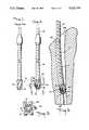
- FIG. 1is a prior art cutting head mounted on a flexible drive shaft
- FIG. 2is side view of the cutting head of the present invention
- FIG. 3is a plan view, partially in cross-section, of the cutting head of the present invention through line 3--3 of FIG.
- FIG. 4is a bottom view of the cutting head of the present invention through line 4--4 of FIG. 2;
- FIG. 5is a side view of the cutting head of the present invention mounted on a flexible reamer and reaming the medullary canal of a femur shown in cross-section;
- FIG. 6is an enlarged cross-sectional view on a plane including the axis of rotation of the cutting head of the present invention within a medullary canal;
- FIG. 7is a cross-sectional view of the cutting head along line 7--7 of FIG. 6;
- FIG. 8is a cross-sectional view of the cutting head of the present invention engaging the end of a long bone and showing the teeth of the tip portion drilling a hole therein to be reamed;
- FIG. 9is a cross-sectional view of an alternate embodiment of the cutting head of the present invention with a generally elliptical cutting surface.
- FIG. 10is still another alternate embodiment of the present invention showing a cutting surface with a generally circular cross-section.
- Prior art cutting head 10has a conically shaped leading end 12 and a generally cylindrical trailing end 13.
- cutting head 14is rigidly connected to or integral with a drive shaft 16 which can be flexible in nature.
- Drive shaft 16includes a drive connector 18 which may be connected to any suitable electrical or pneumatically powered tool (not shown).
- the cutting head 14includes a plurality of flutes 20 separated by generally V-shaped grooves 21 which extend from a leading tip portion 22 to a trailing portion 24 adjacent drive shaft 16. Flutes 20 may extend around cutting head 14 either in a helical fashion or may extend generally parallel to an axis of rotation 25. In the preferred embodiment the diameter of cutting head 14 at the termination of trailing end 24 is approximately the same diameter as drive shaft 16. Upon rotation about axis 25, cutting head 14 generates a cutting surface based on the shape of flutes 20. The number of flutes 20 (normally four to six) and their circumferential width is generally the same as in the prior art. As can be seen in FIGS. 2 and 5, the width of each flute 20 may widen as it extends from tip portion 22 to end 24.
- FIGS. 6 and 8a preferred shape, in cross-section, of flutes 20 is shown. It can be seen that the preferred flutes have a cross-section formed by a first conical section 26 which extends from a starting point 28 at the tip portion 22 of cutting head 14 and extends radially outwardly to a terminating point 30 adjacent the apex or major diameter 33 of cutting head 14. Point 30 is located a predetermined axial distance from starting point 28 towards trailing portion 24. Thus cutting head 14 starts at a first predetermined diameter 29 at point 28 and increases in diameter to a larger diameter at point 30.
- Preferred cutting head 14has a second conical portion 32 starting at a point 34 adjacent trailing end 24 of cutting head 14 which starting point 34 is spaced a predetermined axial distance from starting point 28 at tip 22.
- Conical surface 32extends radially outwardly from starting point 34 to a terminating point 36.
- cutting head 14has a second predetermined diameter 35 at point 34 and increases in diameter to point 36. Neither the first and second predetermined diameters nor the diameters at points 30 and 36 have to be equal.
- Cutting head 14includes a third portion 38 which extends between the terminating point 30 of first conical portion 26 and terminating point 36 of second conical portion 32.
- the third portion 38is either in the form of a sector of a sphere with its major diameter forming the apex 33 of the flute 20 or a torus with a sector of its outer surface forming the apex of the cutting surface.
- Major diameter 33is, of course, larger than the diameters at points 30 and 36.
- the conical portions 26 and 32intersect with spherical or torodial sector 38 tangentially at terminating points 30 and 36 respectively, thereby forming a smooth transition surface with a maximum diameter at the apex 33.
- the tip portion 22 at the leading end of cutting head 14has an inwardly beveled portion 50 extending radially and axially inwardly towards a central bore 52 within cutting head 14 and a shaft 16. Teeth 54 are formed on each flute 20 adjacent the intersection of flutes 20 with tip portion 22. Central bore 52 receives the typical guide shaft 55 for aligning cutting head 14 within the bone canal.
- FIG. 5there is shown the reaming head 14 of the present invention used to enlarge a bore 58 within a medullary canal 60 of a femur 62.
- teeth 54 of cutting head 14allow the cutting head of the present invention to be used to start drilling the bore within the femur as well as to enlarge the bore. Without teeth 54 it would be impossible to start drilling a bore in a flattened surface.
- FIG. 7there is shown a cross-sectional view of the cutting head of the present invention wherein a cutting edge 66 is formed on a leading side on each of flutes 20.
- Each cutting surface 66is in the form of an arc with the shape described above with reference to FIG. 6 so that when high speed rotation of the reaming device occurs, a cutting surface as described above is formed (two cones with a spherical or torodial sector in between).
- the preferred angular orientation of cutting edge 66 with respect to a radial line through the axis of rotation 25is such as to produce a positive rake angle ⁇ of approximately 7°. Although other rake angles could be used, a positive rake angle ensures efficient, low temperature cutting of bone within the canal.
- FIGS. 9 and 10show two alternate embodiments wherein instead of the cutting surface or cutting edge 66 being formed by the rotation of a cutting head 14 having two conical portions at the leading and trailing end with a central spherical or torodial portion the cutting heads have pure curvilinear or arced cutting surfaces from the tip portion to the trailing end of cutting head 14.
- FIG. 9shows a cross-section of a cutting head 14' wherein the cutting edge of the flutes has the general form of an ellipse forming, on rotation, an ellipsoidal cutting surface.
- the cross-section of the cutting head 14"shown in FIG. 10, discloses a cutting surface formed by the rotation of a circular cutting edge which would form a spherical cutting surface.
- Clearly other arc formscan be used to produce a cutting surface as described.
- the already described cutting head profilewherein the cutting head forms a cutting surface having a first predetermined diameter at the tip portion and a larger major diameter 33 at the apex, which apex is spaced a predetermined axial distance from tip portion 22, and then deceasing in radial distance from the axis of rotation towards starting points 34' and 34" at the trailing end of cutting heads 14' and 14" fits all the above described embodiments.
- This geometryensures the ability of the cutting head to cut a bore having the size of the major diameter at apex 33, 33' and 33", no matter what orientation axis of rotation 25 of the cutting head takes with respect to the axis of bore 60.
- Typical dimensions for the cutting head 14 of the present inventioninclude a major diameter of between 0.25 and 1.0 inches and an overall length (from point 28 to point 34) of between 0.25 to 1.5 inches with the diameter of the tip portion being approximately 0.25 inches. If the curved apex area of the cutting surface is formed by the outer surface of a torus, the diameter of the torus is preferably about 0.25 inches regardless of the major diameter of the cutting head. Thus the center of the toroidal section at any point would not coincide with the axis of rotation unless the major diameter were 0.5 inches.
- cutting head 14will now be briefly described with reference to FIGS. 5-8. If one wishes to enlarge a bore 58 within a medullary canal 60, one would choose a cutting head having a major diameter 33 slightly larger than an existing bore 61. Cutting head 14 would either be integral with flexible drive shaft 16 or be attachable thereto for rotation therewith. Head 14 would then be inserted within the canal with bore 52 receiving guide shaft 55. The reamer would follow guide shaft 55 to enlarge bore 61. Should cutting head 14 be canted with respect to the preferred cutting path, the diameter 58 will be no larger than the major diameter 33 of the outing head.
- head 14may be backed out slightly and, because of the relief provided by second portion 32, which has a decreasing diameter, cutting head 14 would easily work free so that the reaming operation can again proceed.
- first and second conical portions 26, 32are inclined with respect to axis of rotation 25 at an angle of between 20 and 40°. With these angles, the reaming and backing off of the reamer can be easily accomplished and with only a small production of cutting heat during reaming.
- This advantageoccurs because the cutting chips formed are efficiently carried by generally V-shaped groove 21 away from the area of the apex 33 of the cutting surface. This is because the bone is cut along the short cutting length 70 of the flute in the area of the apex and the decreasing diameter of the cutting surface toward trailing end. The decreasing diameter of portion 32 allows the bone chips to move out of engagement with the surface of the bore being reamed and the flutes.
- the angle that the first conical portion 26 forms with axis of rotation 25is equal to the angle formed by second conical portion 32 with axis 25.
- the major diameter 33 of cutting head 14is located at a greater axial distance from starting point 28 than the midpoint between points 28 and 34.
- conical section 26is longer than conical section 32 and therefore providing a longer cutting surface 70.
- Cutting length 70can be varied by changing the angles of conical portions 26.
Landscapes
- Health & Medical Sciences (AREA)
- Life Sciences & Earth Sciences (AREA)
- Surgery (AREA)
- Orthopedic Medicine & Surgery (AREA)
- Veterinary Medicine (AREA)
- General Health & Medical Sciences (AREA)
- Oral & Maxillofacial Surgery (AREA)
- Engineering & Computer Science (AREA)
- Biomedical Technology (AREA)
- Heart & Thoracic Surgery (AREA)
- Public Health (AREA)
- Animal Behavior & Ethology (AREA)
- Molecular Biology (AREA)
- Nuclear Medicine, Radiotherapy & Molecular Imaging (AREA)
- Medical Informatics (AREA)
- Dentistry (AREA)
- Transplantation (AREA)
- Physical Education & Sports Medicine (AREA)
- Cardiology (AREA)
- Vascular Medicine (AREA)
- Surgical Instruments (AREA)
- Acyclic And Carbocyclic Compounds In Medicinal Compositions (AREA)
- Prostheses (AREA)
Abstract
Description
Claims (16)
Priority Applications (13)
| Application Number | Priority Date | Filing Date | Title |
|---|---|---|---|
| US07/474,425US5122134A (en) | 1990-02-02 | 1990-02-02 | Surgical reamer |
| EP91300552AEP0440371B1 (en) | 1990-02-02 | 1991-01-24 | Surgical reamer |
| AT91300552TATE145809T1 (en) | 1990-02-02 | 1991-01-24 | SURGICAL REAMER |
| DE69123369TDE69123369T2 (en) | 1990-02-02 | 1991-01-24 | Surgical reamer |
| DK91300552.6TDK0440371T3 (en) | 1990-02-02 | 1991-01-24 | Surgical cleanser |
| ES91300552TES2094196T3 (en) | 1990-02-02 | 1991-01-24 | SURGICAL STRAWBERRY. |
| IE33291AIE75899B1 (en) | 1990-02-02 | 1991-01-31 | Surgical Reamer |
| CA002035379ACA2035379C (en) | 1990-02-02 | 1991-01-31 | Surgical reamer |
| KR1019910001781AKR930003331B1 (en) | 1990-02-02 | 1991-02-01 | Surgical reamer |
| AU70225/91AAU625710B2 (en) | 1990-02-02 | 1991-02-01 | Surgical reamer |
| JP3098379AJPH0815488B2 (en) | 1990-02-02 | 1991-02-01 | Cutting head |
| DE9101151UDE9101151U1 (en) | 1990-02-02 | 1991-02-01 | Cutting head for a surgical awl |
| GR960403305TGR3022326T3 (en) | 1990-02-02 | 1997-01-22 | Surgical reamer |
Applications Claiming Priority (1)
| Application Number | Priority Date | Filing Date | Title |
|---|---|---|---|
| US07/474,425US5122134A (en) | 1990-02-02 | 1990-02-02 | Surgical reamer |
Publications (1)
| Publication Number | Publication Date |
|---|---|
| US5122134Atrue US5122134A (en) | 1992-06-16 |
Family
ID=23883479
Family Applications (1)
| Application Number | Title | Priority Date | Filing Date |
|---|---|---|---|
| US07/474,425Expired - LifetimeUS5122134A (en) | 1990-02-02 | 1990-02-02 | Surgical reamer |
Country Status (12)
| Country | Link |
|---|---|
| US (1) | US5122134A (en) |
| EP (1) | EP0440371B1 (en) |
| JP (1) | JPH0815488B2 (en) |
| KR (1) | KR930003331B1 (en) |
| AT (1) | ATE145809T1 (en) |
| AU (1) | AU625710B2 (en) |
| CA (1) | CA2035379C (en) |
| DE (2) | DE69123369T2 (en) |
| DK (1) | DK0440371T3 (en) |
| ES (1) | ES2094196T3 (en) |
| GR (1) | GR3022326T3 (en) |
| IE (1) | IE75899B1 (en) |
Cited By (134)
| Publication number | Priority date | Publication date | Assignee | Title |
|---|---|---|---|---|
| WO1995017126A1 (en)* | 1993-12-22 | 1995-06-29 | Radi Medical Systems Ab | Device for biopsy sampling |
| US5439464A (en)* | 1993-03-09 | 1995-08-08 | Shapiro Partners Limited | Method and instruments for performing arthroscopic spinal surgery |
| US5443468A (en)* | 1994-02-04 | 1995-08-22 | Johnson; Lanny L. | Method for drilling a bore in bone using a compaction drill |
| US5496326A (en)* | 1991-06-27 | 1996-03-05 | Johnson; Lanny L. | Fixation screw and method for ligament reconstruction |
| US5499985A (en)* | 1993-11-24 | 1996-03-19 | Orthopaedic Innovations, Inc. | Detachable coupling system for surgical instruments |
| US5514141A (en)* | 1992-11-18 | 1996-05-07 | Howmedica, Inc. | Small joint reamer |
| WO1996025113A1 (en)* | 1995-02-16 | 1996-08-22 | Johnson Lanny L | Method and apparatus for forming a centered bore for the femoral stem of a hip prosthesis |
| US5562673A (en)* | 1994-03-03 | 1996-10-08 | Howmedica Inc. | Awls for sizing bone canals |
| US5591170A (en)* | 1994-10-14 | 1997-01-07 | Genesis Orthopedics | Intramedullary bone cutting saw |
| WO1997003611A1 (en)* | 1995-07-18 | 1997-02-06 | Edwards, Garland, U. | Flexible shaft |
| US5607431A (en)* | 1995-02-09 | 1997-03-04 | Howmedica Inc. | Prosthetic hip implantation method and apparatus |
| USD378780S (en)* | 1994-03-07 | 1997-04-08 | Arthrex Inc. | Cannulated headed reamer |
| US5645545A (en)* | 1995-08-14 | 1997-07-08 | Zimmer, Inc. | Self reaming intramedullary nail and method for using the same |
| US5690634A (en)* | 1993-09-15 | 1997-11-25 | Synthes (U.S.A.) | Medullary drill head |
| US5697932A (en)* | 1994-11-09 | 1997-12-16 | Osteonics Corp. | Bone graft delivery system and method |
| US5709697A (en)* | 1995-11-22 | 1998-01-20 | United States Surgical Corporation | Apparatus and method for removing tissue |
| US5720749A (en)* | 1996-03-18 | 1998-02-24 | Snap-On Technologies, Inc. | Integral reamer apparatus with guide counterbores in female press-fitted parts |
| US5755719A (en)* | 1997-01-15 | 1998-05-26 | Case Medical, Inc. | Acetabular reamer |
| WO1998049945A1 (en)* | 1997-05-08 | 1998-11-12 | Surgical Dynamics, Inc. | Multiple bladed surgical cutting device removably connected to a rotary drive element |
| US5908423A (en)* | 1993-05-27 | 1999-06-01 | Howmedica, Inc. | Flexible medullary reaming system |
| US5925056A (en)* | 1996-04-12 | 1999-07-20 | Surgical Dynamics, Inc. | Surgical cutting device removably connected to a rotary drive element |
| US5941883A (en)* | 1996-06-04 | 1999-08-24 | Sklar; Joseph H. | Apparatus and method for reconstructing ligaments |
| US5968048A (en)* | 1995-07-22 | 1999-10-19 | Howmedica Gmbh | Bore head for boring bone channels |
| EP0965308A1 (en) | 1998-06-17 | 1999-12-22 | Precifar S.A. | Surgical reamer |
| US6033407A (en)* | 1998-01-27 | 2000-03-07 | Behrens; Alfred F. | Apparatus and method for intramedullary nailing and intramedullary nail therefor |
| US6168599B1 (en)* | 1997-04-14 | 2001-01-02 | Allan S. Frieze | Long bone reamer |
| US6200319B1 (en) | 1998-10-23 | 2001-03-13 | Benoist Girard Sas | Surgical trephine |
| US6258093B1 (en) | 1999-02-01 | 2001-07-10 | Garland U. Edwards | Surgical reamer cutter |
| US6332886B1 (en) | 1999-02-03 | 2001-12-25 | Synthes (Usa) | Surgical reamer and method of using same |
| US6416517B2 (en)* | 1997-08-04 | 2002-07-09 | Stryker Trauma Gmbh | Reaming tool for reaming bone canals |
| US6431801B2 (en)* | 1999-12-10 | 2002-08-13 | Maxtech Manufacturing Inc. | Drill bit for non-linear drilling |
| US20020133156A1 (en)* | 1999-06-10 | 2002-09-19 | Cole J. Dean | Femoral intramedullary rod system |
| US20020165550A1 (en)* | 1999-10-21 | 2002-11-07 | George Frey | Devices and techniques for a posterior lateral disc space approach |
| US6524319B1 (en)* | 1998-12-22 | 2003-02-25 | Ferton Holding S.A. | Surgical instrument for mechanically removing bone cement |
| US20040006358A1 (en)* | 2000-04-05 | 2004-01-08 | Pathway Medical Technologies, Inc. | Intralumenal material removal using a cutting device for differential cutting |
| US20040030346A1 (en)* | 1999-10-21 | 2004-02-12 | George Frey | Devices and techniques for a posterior lateral disc space approach |
| US20040087956A1 (en)* | 2000-09-01 | 2004-05-06 | Synthes (U.S.A) | Tools and methods for creating cavities in bone |
| EP1433439A2 (en) | 1994-04-28 | 2004-06-30 | Boston Scientific Corporation | Endoprothesis |
| US6764491B2 (en) | 1999-10-21 | 2004-07-20 | Sdgi Holdings, Inc. | Devices and techniques for a posterior lateral disc space approach |
| US20040162563A1 (en)* | 2000-12-14 | 2004-08-19 | Michelson Gary K. | Spinal interspace shaper |
| US6783532B2 (en) | 1999-02-02 | 2004-08-31 | Synthes (Usa) | Device for removing bone tissue |
| US6783533B2 (en) | 2001-11-21 | 2004-08-31 | Sythes Ag Chur | Attachable/detachable reaming head for surgical reamer |
| US6821280B1 (en)* | 2000-08-03 | 2004-11-23 | Charanpreet S. Bagga | Distracting and curetting instrument |
| US20040267268A1 (en)* | 1999-11-23 | 2004-12-30 | Nuvasive, Inc. | Bone graft harvester and related methods |
| US20050015091A1 (en)* | 1997-10-06 | 2005-01-20 | Sdgi Holdings Inc. | Drill head for use in placing an intervertebral disc device |
| US20050096685A1 (en)* | 2003-10-31 | 2005-05-05 | Medtronic, Inc. | Surgical instrument with adjustable rotary cutting tool and method of cutting |
| US20060100633A1 (en)* | 1998-06-09 | 2006-05-11 | Michelson Gary K | Method for preparing a space in bone to receive an insert |
| US20060106393A1 (en)* | 2004-11-12 | 2006-05-18 | Huebner Randall J | Bone reamer |
| US20060142775A1 (en)* | 2004-12-29 | 2006-06-29 | Depuy Mitek, Inc. | Surgical tool with cannulated rotary tip |
| US20060235431A1 (en)* | 2005-04-15 | 2006-10-19 | Cook Vascular Incorporated | Lead extraction device |
| US20060259055A1 (en)* | 2005-05-13 | 2006-11-16 | Linvatec Corporation | Attachments for arthroscopic shaver handpieces |
| US20070015102A1 (en)* | 2005-06-21 | 2007-01-18 | Tomaso Vercellotti | Implant site preparation method and relative piezoelectric surgical device |
| US20070050028A1 (en)* | 2005-08-26 | 2007-03-01 | Conner E S | Spinal implants and methods of providing dynamic stability to the spine |
| US20070055281A1 (en)* | 1994-01-26 | 2007-03-08 | Kyphon Inc. | Methods for treating a fractured and/or diseased vertebral body by incremental introduction of bone filling material |
| US20070244562A1 (en)* | 2005-08-26 | 2007-10-18 | Magellan Spine Technologies, Inc. | Spinal implants and methods of providing dynamic stability to the spine |
| US20080004643A1 (en)* | 2006-06-30 | 2008-01-03 | Atheromed, Inc. | Atherectomy devices and methods |
| US20080071341A1 (en)* | 2005-04-15 | 2008-03-20 | Cook Vascular Incorporated | Tip for lead extraction device |
| US20080132929A1 (en)* | 2005-07-19 | 2008-06-05 | O'sullivan Denis F | Surgical bur with anti-chatter flute geometry |
| US20080275449A1 (en)* | 2007-05-02 | 2008-11-06 | Sackett Samuel G | Expandable proximal reamer |
| US20080275448A1 (en)* | 2007-05-02 | 2008-11-06 | Sackett Samuel G | Expandable proximal reamer |
| US20080287958A1 (en)* | 2007-05-14 | 2008-11-20 | Howmedica Osteonics Corp. | Flexible intramedullary rod |
| US20090024118A1 (en)* | 1999-12-21 | 2009-01-22 | Piezosurgery Inc. | Surgical Device For Bone Surgery |
| US20090024085A1 (en)* | 2006-06-30 | 2009-01-22 | Artheromed, Inc | Atherectomy devices, systems, and methods |
| US20090076511A1 (en)* | 2007-09-14 | 2009-03-19 | Osman Said G | Intervertebral Disc Reamer |
| US20090138084A1 (en)* | 2007-11-19 | 2009-05-28 | Magellan Spine Technologies, Inc. | Spinal implants and methods |
| US20090149878A1 (en)* | 2007-12-07 | 2009-06-11 | Csaba Truckai | Bone treatment systems and methods |
| USD595850S1 (en)* | 2007-02-09 | 2009-07-07 | Gebr. Brasseler Gmbh & Co. Kg | Dental instrument |
| US20090208902A1 (en)* | 2008-02-20 | 2009-08-20 | Gebr. Brasseler Gmbh & Co. Kg | Dental drill made of plastics |
| US20100167235A1 (en)* | 2006-09-25 | 2010-07-01 | Piezosurgery S.R.L. | Handpiece with surgical tool to perform holes in bone tissues |
| US20100174286A1 (en)* | 2004-11-10 | 2010-07-08 | Dfine, Inc. | Bone treatment systems and methods for introducing an abrading structure to abrade bone |
| US20100204672A1 (en)* | 2009-02-12 | 2010-08-12 | Penumra, Inc. | System and method for treating ischemic stroke |
| US20100239380A1 (en)* | 2007-07-31 | 2010-09-23 | Stryker Trauma Gmbh | Carbon shafted reaming device |
| US20110015675A1 (en)* | 2009-07-16 | 2011-01-20 | Howmedica Osteonics Corp. | Suture anchor implantation instrumentation system |
| US20110143308A1 (en)* | 2008-08-21 | 2011-06-16 | Gangnam Chicago Dental Clinic , 7F | Piezo insert for implant surgical operation |
| US20110144649A1 (en)* | 2009-12-15 | 2011-06-16 | Greatbatch Ltd. | Disposable Flex Reamer |
| USD641472S1 (en)* | 2009-02-04 | 2011-07-12 | Shofu Inc. | Dental rotary instrument |
| US20110208194A1 (en)* | 2009-08-20 | 2011-08-25 | Howmedica Osteonics Corp. | Flexible acl instrumentation, kit and method |
| USD644737S1 (en)* | 2008-09-05 | 2011-09-06 | Shofu Inc. | Dental instrument |
| USD656609S1 (en)* | 2009-06-03 | 2012-03-27 | Juan J. Perez | Swab |
| US8287538B2 (en) | 2008-01-14 | 2012-10-16 | Conventus Orthopaedics, Inc. | Apparatus and methods for fracture repair |
| WO2013056262A1 (en)* | 2011-10-13 | 2013-04-18 | Atheromed, Inc. | Atherectomy apparatus, systems and methods |
| US8518044B2 (en) | 2007-02-09 | 2013-08-27 | Christopher G. Sidebotham | Disposable flexible reamer shaft for medical applications |
| US20140081271A1 (en)* | 2012-09-20 | 2014-03-20 | Depuy Mitek, Llc | Low profile reamers and methods of use |
| US20140236156A1 (en)* | 2011-09-16 | 2014-08-21 | CHIRMAT Sàrl | Surgical tool for reaming the diaphyseal canal of long bones |
| US8821494B2 (en) | 2012-08-03 | 2014-09-02 | Howmedica Osteonics Corp. | Surgical instruments and methods of use |
| US8888801B2 (en) | 2006-06-30 | 2014-11-18 | Atheromed, Inc. | Atherectomy devices and methods |
| US8906022B2 (en) | 2010-03-08 | 2014-12-09 | Conventus Orthopaedics, Inc. | Apparatus and methods for securing a bone implant |
| US8961518B2 (en) | 2010-01-20 | 2015-02-24 | Conventus Orthopaedics, Inc. | Apparatus and methods for bone access and cavity preparation |
| US9011444B2 (en) | 2011-12-09 | 2015-04-21 | Howmedica Osteonics Corp. | Surgical reaming instrument for shaping a bone cavity |
| US9078740B2 (en) | 2013-01-21 | 2015-07-14 | Howmedica Osteonics Corp. | Instrumentation and method for positioning and securing a graft |
| US9095371B2 (en) | 2007-10-22 | 2015-08-04 | Atheromed, Inc. | Atherectomy devices and methods |
| US9149282B2 (en) | 2011-12-30 | 2015-10-06 | Howmedica Osteonics Corp. | Systems and methods for preparing bone voids to receive a prosthesis |
| US9232952B2 (en) | 2012-04-16 | 2016-01-12 | Medtronic Ps Medical, Inc. | Surgical bur with non-paired flutes |
| US9345489B2 (en) | 2010-03-31 | 2016-05-24 | Stryker European Holdings I, Llc | Reaming device with carbon fiber shaft and molded interface element |
| US9402620B2 (en) | 2013-03-04 | 2016-08-02 | Howmedica Osteonics Corp. | Knotless filamentary fixation devices, assemblies and systems and methods of assembly and use |
| US20160287267A1 (en)* | 2015-03-31 | 2016-10-06 | Medtronic Xomed, Inc. | Surgical Burs With Localized Auxiliary Flutes |
| US9463013B2 (en) | 2013-03-13 | 2016-10-11 | Stryker Corporation | Adjustable continuous filament structure and method of manufacture and use |
| US9492193B2 (en) | 2006-06-30 | 2016-11-15 | Atheromed, Inc. | Devices, systems, and methods for cutting and removing occlusive material from a body lumen |
| US9526513B2 (en) | 2013-03-13 | 2016-12-27 | Howmedica Osteonics Corp. | Void filling joint prosthesis and associated instruments |
| US9586041B2 (en) | 2013-08-26 | 2017-03-07 | Cook Medical Technologies Llc | Enhanced outer sheath for extraction device |
| US9649490B2 (en) | 2011-06-16 | 2017-05-16 | Cook Medical Technologies Llc | Tip for lead extraction device |
| US9675376B2 (en) | 2006-06-30 | 2017-06-13 | Atheromed, Inc. | Atherectomy devices and methods |
| US9730739B2 (en) | 2010-01-15 | 2017-08-15 | Conventus Orthopaedics, Inc. | Rotary-rigid orthopaedic rod |
| US9788826B2 (en) | 2013-03-11 | 2017-10-17 | Howmedica Osteonics Corp. | Filamentary fixation device and assembly and method of assembly, manufacture and use |
| US9795398B2 (en) | 2011-04-13 | 2017-10-24 | Howmedica Osteonics Corp. | Flexible ACL instrumentation, kit and method |
| US9808242B2 (en) | 2012-04-06 | 2017-11-07 | Howmedica Osteonics Corp. | Knotless filament anchor for soft tissue repair |
| US9883873B2 (en) | 2013-07-17 | 2018-02-06 | Medtronic Ps Medical, Inc. | Surgical burs with geometries having non-drifting and soft tissue protective characteristics |
| WO2018035034A1 (en)* | 2016-08-14 | 2018-02-22 | Greatbatch Ltd. | Cutting head for an intramedullary reamer |
| US20180078279A1 (en)* | 2016-09-20 | 2018-03-22 | RELIGN Corporation | Arthroscopic devices and methods |
| US9986992B2 (en) | 2014-10-28 | 2018-06-05 | Stryker Corporation | Suture anchor and associated methods of use |
| US10022132B2 (en) | 2013-12-12 | 2018-07-17 | Conventus Orthopaedics, Inc. | Tissue displacement tools and methods |
| US10226275B2 (en) | 2006-06-30 | 2019-03-12 | Atheromed, Inc. | Devices, systems, and methods for debulking restenosis of a blood vessel |
| US10265082B2 (en) | 2015-08-31 | 2019-04-23 | Medtronic Ps Medical, Inc. | Surgical burs |
| US10335166B2 (en) | 2014-04-16 | 2019-07-02 | Medtronics Ps Medical, Inc. | Surgical burs with decoupled rake surfaces and corresponding axial and radial rake angles |
| US10335170B2 (en) | 2016-02-12 | 2019-07-02 | Viant As&O Holdings, Llc | Cutting heads for intramedullary reamers |
| US10448944B2 (en) | 2011-11-23 | 2019-10-22 | Howmedica Osteonics Corp. | Filamentary fixation device |
| US10568616B2 (en) | 2014-12-17 | 2020-02-25 | Howmedica Osteonics Corp. | Instruments and methods of soft tissue fixation |
| US10610211B2 (en) | 2013-12-12 | 2020-04-07 | Howmedica Osteonics Corp. | Filament engagement system and methods of use |
| US10631880B1 (en)* | 2015-12-01 | 2020-04-28 | Innovative Medical Solutions LLC | Cannulated modular magnetic glenoid reamer |
| USD902405S1 (en) | 2018-02-22 | 2020-11-17 | Stryker Corporation | Self-punching bone anchor inserter |
| US10918426B2 (en) | 2017-07-04 | 2021-02-16 | Conventus Orthopaedics, Inc. | Apparatus and methods for treatment of a bone |
| US11000305B2 (en) | 2017-08-02 | 2021-05-11 | Stryker Corporation | Surgical tool systems, and methods of use thereof |
| US11039852B2 (en)* | 2016-09-16 | 2021-06-22 | Terumo Kabushiki Kaisha | Medical device |
| US11123086B1 (en)* | 2019-01-04 | 2021-09-21 | Innovative Medical Solutions LLC | Cannulated modular magnetic glenoid reamer |
| US11123085B2 (en) | 2018-04-11 | 2021-09-21 | Howmedica Osteonics Corp. | Cutting tool positioned by flexible rod for revision surgery |
| US11173034B2 (en) | 2015-01-12 | 2021-11-16 | Howmedica Osteonics Corp. | Bone void forming apparatus |
| US11207096B2 (en) | 2006-06-30 | 2021-12-28 | Atheromed, Inc. | Devices systems and methods for cutting and removing occlusive material from a body lumen |
| US11219466B2 (en) | 2018-06-06 | 2022-01-11 | Acumed Llc | Orthopedic reamer with expandable cutting head |
| US11304723B1 (en) | 2020-12-17 | 2022-04-19 | Avantec Vascular Corporation | Atherectomy devices that are self-driving with controlled deflection |
| US11331094B2 (en) | 2013-04-22 | 2022-05-17 | Stryker Corporation | Method and apparatus for attaching tissue to bone |
| US11596419B2 (en) | 2017-03-09 | 2023-03-07 | Flower Orthopedics Corporation | Plating depth gauge and countersink instrument |
| US12220140B1 (en) | 2023-08-16 | 2025-02-11 | Avantec Vascular Corporation | Thrombectomy devices with lateral and vertical bias |
| US12290279B2 (en) | 2021-06-07 | 2025-05-06 | Avantec Vascular Corporation | Hybrid atherectomy devices |
| US12414785B1 (en) | 2025-03-17 | 2025-09-16 | Avantec Vascular Corporation | Cutters with pulsating vacuum control |
Families Citing this family (12)
| Publication number | Priority date | Publication date | Assignee | Title |
|---|---|---|---|---|
| US5190548A (en)* | 1991-04-10 | 1993-03-02 | Linvatec Corporation | Surgical reamer |
| DE19528242A1 (en)* | 1995-08-01 | 1997-02-06 | Roland Dr Dr Streckbein | Instrument for preparing cavities in bone spongiosa for receiving implants - has threaded section, slightly conical, and head for rotating it, forcing bone cavity wall material radially towards outside |
| US6312438B1 (en)* | 2000-02-01 | 2001-11-06 | Medtronic Xomed, Inc. | Rotary bur instruments having bur tips with aspiration passages |
| DE10151355A1 (en)* | 2001-10-22 | 2003-04-30 | Herbert Hatzlhoffer | Surgical tool |
| CA2546871C (en)* | 2003-11-28 | 2012-09-04 | Favre, Marc-Etienne | Surgery bur |
| CN101208046B (en)* | 2005-03-29 | 2011-01-12 | Hi-Lex株式会社 | Medical double needles, bone puncture needles and bone marrow collection equipment |
| US8641717B2 (en) | 2010-07-01 | 2014-02-04 | DePuy Synthes Products, LLC | Guidewire insertion methods and devices |
| DE102010049455A1 (en)* | 2010-10-22 | 2012-04-26 | Igor Nikiforov | Instrument for minimally invasive surgery in the field of spinal fusion on the human or animal body |
| US9707069B2 (en) | 2011-02-25 | 2017-07-18 | Avinash Kumar | Suture mesh and method of use |
| CN102824204B (en)* | 2012-09-26 | 2014-12-17 | 中国人民解放军第三军医大学第三附属医院 | Medical multifunctional operating bit |
| CN102871701B (en)* | 2012-09-26 | 2015-06-17 | 中国人民解放军第三军医大学第三附属医院 | Medical combined operation drill bit |
| CN111212616B (en)* | 2017-10-13 | 2022-04-12 | 捷迈有限公司 | Revision knee arthroplasty methods and instruments |
Citations (12)
| Publication number | Priority date | Publication date | Assignee | Title |
|---|---|---|---|---|
| US533573A (en)* | 1895-02-05 | John d | ||
| US930477A (en)* | 1908-08-08 | 1909-08-10 | William Henry Hudson | Trephine. |
| US3495483A (en)* | 1967-03-29 | 1970-02-17 | Emerson Electric Co | Reversible pipe reamer |
| US3554192A (en)* | 1967-07-24 | 1971-01-12 | Orthopedic Equipment Co | Medullary space drill |
| US4273117A (en)* | 1978-09-02 | 1981-06-16 | Neuhaeuser Hans G | Apparatus for drilling bone |
| US4538989A (en)* | 1979-10-01 | 1985-09-03 | Dentsply International, Inc. | Dental reamer |
| US4541423A (en)* | 1983-01-17 | 1985-09-17 | Barber Forest C | Drilling a curved hole |
| US4586497A (en)* | 1983-10-31 | 1986-05-06 | David J. Dapra | Drill fixation device and method for vertebra cutting |
| US4594034A (en)* | 1982-09-14 | 1986-06-10 | Hartmetallwerkzeugfabrik Andreas Maier Gmbh & Co. Kg | Multigroove drill bit with angled frontal ridges |
| US4706659A (en)* | 1984-12-05 | 1987-11-17 | Regents Of The University Of Michigan | Flexible connecting shaft for intramedullary reamer |
| US4751992A (en)* | 1985-04-04 | 1988-06-21 | Luk Lamellen Und Kupplungsbau Gmbh | Composite flywheel with slip clutch |
| US4951690A (en)* | 1984-01-31 | 1990-08-28 | Baker John W | Method of drilling through a bone structure |
Family Cites Families (4)
| Publication number | Priority date | Publication date | Assignee | Title |
|---|---|---|---|---|
| US3867943A (en)* | 1972-09-13 | 1975-02-25 | Weck & Co Edward | Surgical drill with detachable hand-piece |
| US3847154A (en)* | 1972-09-22 | 1974-11-12 | Weck & Co Edward | Surgical drill with detachable hand-piece |
| US4473070A (en)* | 1983-01-05 | 1984-09-25 | Regents Of The University Of Michigan | Intramedullary reamer |
| US4751922A (en)* | 1986-06-27 | 1988-06-21 | Dipietropolo Al | Flexible medullary reamer |
- 1990
- 1990-02-02USUS07/474,425patent/US5122134A/ennot_activeExpired - Lifetime
- 1991
- 1991-01-24EPEP91300552Apatent/EP0440371B1/ennot_activeExpired - Lifetime
- 1991-01-24ATAT91300552Tpatent/ATE145809T1/ennot_activeIP Right Cessation
- 1991-01-24DKDK91300552.6Tpatent/DK0440371T3/enactive
- 1991-01-24DEDE69123369Tpatent/DE69123369T2/ennot_activeExpired - Lifetime
- 1991-01-24ESES91300552Tpatent/ES2094196T3/ennot_activeExpired - Lifetime
- 1991-01-31IEIE33291Apatent/IE75899B1/ennot_activeIP Right Cessation
- 1991-01-31CACA002035379Apatent/CA2035379C/ennot_activeExpired - Lifetime
- 1991-02-01DEDE9101151Upatent/DE9101151U1/ennot_activeExpired - Lifetime
- 1991-02-01AUAU70225/91Apatent/AU625710B2/ennot_activeExpired
- 1991-02-01JPJP3098379Apatent/JPH0815488B2/ennot_activeExpired - Lifetime
- 1991-02-01KRKR1019910001781Apatent/KR930003331B1/ennot_activeExpired - Fee Related
- 1997
- 1997-01-22GRGR960403305Tpatent/GR3022326T3/enunknown
Patent Citations (12)
| Publication number | Priority date | Publication date | Assignee | Title |
|---|---|---|---|---|
| US533573A (en)* | 1895-02-05 | John d | ||
| US930477A (en)* | 1908-08-08 | 1909-08-10 | William Henry Hudson | Trephine. |
| US3495483A (en)* | 1967-03-29 | 1970-02-17 | Emerson Electric Co | Reversible pipe reamer |
| US3554192A (en)* | 1967-07-24 | 1971-01-12 | Orthopedic Equipment Co | Medullary space drill |
| US4273117A (en)* | 1978-09-02 | 1981-06-16 | Neuhaeuser Hans G | Apparatus for drilling bone |
| US4538989A (en)* | 1979-10-01 | 1985-09-03 | Dentsply International, Inc. | Dental reamer |
| US4594034A (en)* | 1982-09-14 | 1986-06-10 | Hartmetallwerkzeugfabrik Andreas Maier Gmbh & Co. Kg | Multigroove drill bit with angled frontal ridges |
| US4541423A (en)* | 1983-01-17 | 1985-09-17 | Barber Forest C | Drilling a curved hole |
| US4586497A (en)* | 1983-10-31 | 1986-05-06 | David J. Dapra | Drill fixation device and method for vertebra cutting |
| US4951690A (en)* | 1984-01-31 | 1990-08-28 | Baker John W | Method of drilling through a bone structure |
| US4706659A (en)* | 1984-12-05 | 1987-11-17 | Regents Of The University Of Michigan | Flexible connecting shaft for intramedullary reamer |
| US4751992A (en)* | 1985-04-04 | 1988-06-21 | Luk Lamellen Und Kupplungsbau Gmbh | Composite flywheel with slip clutch |
Non-Patent Citations (7)
| Title |
|---|
| Larry S. Matthews, M. D. & Steven A. Goldstein, Ph.D., "A New Intramedullary Reamer Design" Scientific Exhibit presented at the 51st Annual Meeting of American Academy of Orthopedic Surgeons, Atlanta, GA Feb. 9-14, 1984. |
| Larry S. Matthews, M. D. & Steven A. Goldstein, Ph.D., A New Intramedullary Reamer Design Scientific Exhibit presented at the 51st Annual Meeting of American Academy of Orthopedic Surgeons, Atlanta, GA Feb. 9 14, 1984.* |
| Richards Manufacturing Co. Inc. Orthopedic Catalog No. 15, 1974, p. 50.* |
| Stryker Intl; Catalog dated Jun. 1979 entitled "SurgiPower®-the world's most complete line of powered surgical instruments". |
| Stryker Intl; Catalog dated Jun. 1979 entitled SurgiPower the world s most complete line of powered surgical instruments .* |
| William H. Huelson, M. D., "A New Method of Performing Operations on the Skull"Feb. 1910. |
| William H. Huelson, M. D., A New Method of Performing Operations on the Skull Feb. 1910.* |
Cited By (287)
| Publication number | Priority date | Publication date | Assignee | Title |
|---|---|---|---|---|
| US5496326A (en)* | 1991-06-27 | 1996-03-05 | Johnson; Lanny L. | Fixation screw and method for ligament reconstruction |
| US5514141A (en)* | 1992-11-18 | 1996-05-07 | Howmedica, Inc. | Small joint reamer |
| US5439464A (en)* | 1993-03-09 | 1995-08-08 | Shapiro Partners Limited | Method and instruments for performing arthroscopic spinal surgery |
| US5908423A (en)* | 1993-05-27 | 1999-06-01 | Howmedica, Inc. | Flexible medullary reaming system |
| US5690634A (en)* | 1993-09-15 | 1997-11-25 | Synthes (U.S.A.) | Medullary drill head |
| US5499985A (en)* | 1993-11-24 | 1996-03-19 | Orthopaedic Innovations, Inc. | Detachable coupling system for surgical instruments |
| WO1995017126A1 (en)* | 1993-12-22 | 1995-06-29 | Radi Medical Systems Ab | Device for biopsy sampling |
| US5868684A (en)* | 1993-12-22 | 1999-02-09 | Radi Medical Systems Ab | Device for hard tissue biopsy sampling |
| US20070055281A1 (en)* | 1994-01-26 | 2007-03-08 | Kyphon Inc. | Methods for treating a fractured and/or diseased vertebral body by incremental introduction of bone filling material |
| US5443468A (en)* | 1994-02-04 | 1995-08-22 | Johnson; Lanny L. | Method for drilling a bore in bone using a compaction drill |
| US5562673A (en)* | 1994-03-03 | 1996-10-08 | Howmedica Inc. | Awls for sizing bone canals |
| USD378780S (en)* | 1994-03-07 | 1997-04-08 | Arthrex Inc. | Cannulated headed reamer |
| EP1433439A2 (en) | 1994-04-28 | 2004-06-30 | Boston Scientific Corporation | Endoprothesis |
| US5591170A (en)* | 1994-10-14 | 1997-01-07 | Genesis Orthopedics | Intramedullary bone cutting saw |
| US6142998A (en)* | 1994-11-09 | 2000-11-07 | Howmedica Osteonics Corp. | Bone graft delivery surgical instruments |
| US5697932A (en)* | 1994-11-09 | 1997-12-16 | Osteonics Corp. | Bone graft delivery system and method |
| US6309395B1 (en) | 1994-11-09 | 2001-10-30 | Howmedica Osteonics Corp. | Bone graft delivery surgical instruments |
| US6045555A (en)* | 1994-11-09 | 2000-04-04 | Osteonics Corp. | Bone graft delivery system and method |
| US5607431A (en)* | 1995-02-09 | 1997-03-04 | Howmedica Inc. | Prosthetic hip implantation method and apparatus |
| US5928240A (en)* | 1995-02-16 | 1999-07-27 | Johnson; Lanny L. | Apparatus for forming a centered bore for the femoral stem of a hip prosthesis |
| US5897560A (en)* | 1995-02-16 | 1999-04-27 | Johnson; Lanny L. | Method and apparatus for forming a centered bore for the femoral stem of hip prosthesis |
| WO1996025113A1 (en)* | 1995-02-16 | 1996-08-22 | Johnson Lanny L | Method and apparatus for forming a centered bore for the femoral stem of a hip prosthesis |
| WO1997003611A1 (en)* | 1995-07-18 | 1997-02-06 | Edwards, Garland, U. | Flexible shaft |
| US6053922A (en)* | 1995-07-18 | 2000-04-25 | Krause; William R. | Flexible shaft |
| US5968048A (en)* | 1995-07-22 | 1999-10-19 | Howmedica Gmbh | Bore head for boring bone channels |
| US5645545A (en)* | 1995-08-14 | 1997-07-08 | Zimmer, Inc. | Self reaming intramedullary nail and method for using the same |
| US5709697A (en)* | 1995-11-22 | 1998-01-20 | United States Surgical Corporation | Apparatus and method for removing tissue |
| US5720749A (en)* | 1996-03-18 | 1998-02-24 | Snap-On Technologies, Inc. | Integral reamer apparatus with guide counterbores in female press-fitted parts |
| US5968062A (en)* | 1996-04-12 | 1999-10-19 | Surgical Dynamics, Inc. | Surgical cutting device removeably connected to a rotarty drive element |
| US5925056A (en)* | 1996-04-12 | 1999-07-20 | Surgical Dynamics, Inc. | Surgical cutting device removably connected to a rotary drive element |
| US6685709B2 (en) | 1996-06-04 | 2004-02-03 | Joseph H. Sklar | Apparatus and method for reconstructing ligaments |
| US5941883A (en)* | 1996-06-04 | 1999-08-24 | Sklar; Joseph H. | Apparatus and method for reconstructing ligaments |
| US20040220576A1 (en)* | 1996-06-04 | 2004-11-04 | Sklar Joseph H | Apparatus and method for reconstructing ligaments |
| US6364886B1 (en) | 1996-06-04 | 2002-04-02 | Joseph H. Sklar | Apparatus and method for reconstructing ligaments |
| US5755719A (en)* | 1997-01-15 | 1998-05-26 | Case Medical, Inc. | Acetabular reamer |
| US6168599B1 (en)* | 1997-04-14 | 2001-01-02 | Allan S. Frieze | Long bone reamer |
| WO1998049945A1 (en)* | 1997-05-08 | 1998-11-12 | Surgical Dynamics, Inc. | Multiple bladed surgical cutting device removably connected to a rotary drive element |
| US6416517B2 (en)* | 1997-08-04 | 2002-07-09 | Stryker Trauma Gmbh | Reaming tool for reaming bone canals |
| US20050015091A1 (en)* | 1997-10-06 | 2005-01-20 | Sdgi Holdings Inc. | Drill head for use in placing an intervertebral disc device |
| US7331963B2 (en)* | 1997-10-06 | 2008-02-19 | Warsaw Orthopedic, Inc. | Drill head for use in placing an intervertebral disc device |
| US6033407A (en)* | 1998-01-27 | 2000-03-07 | Behrens; Alfred F. | Apparatus and method for intramedullary nailing and intramedullary nail therefor |
| US20060100633A1 (en)* | 1998-06-09 | 2006-05-11 | Michelson Gary K | Method for preparing a space in bone to receive an insert |
| US8066707B2 (en) | 1998-06-09 | 2011-11-29 | Warsaw Orthopedic, Inc. | Method for preparing a space in bone to receive an insert |
| US8317794B2 (en) | 1998-06-09 | 2012-11-27 | Warsaw Orthopedic, Inc. | Device for preparing a space in bone to receive an insert |
| US6238398B1 (en) | 1998-06-17 | 2001-05-29 | Precifar S.A. | Surgical reamer |
| EP0965308A1 (en) | 1998-06-17 | 1999-12-22 | Precifar S.A. | Surgical reamer |
| US6200319B1 (en) | 1998-10-23 | 2001-03-13 | Benoist Girard Sas | Surgical trephine |
| US6524319B1 (en)* | 1998-12-22 | 2003-02-25 | Ferton Holding S.A. | Surgical instrument for mechanically removing bone cement |
| US6258093B1 (en) | 1999-02-01 | 2001-07-10 | Garland U. Edwards | Surgical reamer cutter |
| US6783532B2 (en) | 1999-02-02 | 2004-08-31 | Synthes (Usa) | Device for removing bone tissue |
| US6332886B1 (en) | 1999-02-03 | 2001-12-25 | Synthes (Usa) | Surgical reamer and method of using same |
| US7867231B2 (en) | 1999-06-10 | 2011-01-11 | Cole J Dean | Femoral intramedullary rod system |
| US20060122600A1 (en)* | 1999-06-10 | 2006-06-08 | Orthodyne, Inc. | Femoral intramedullary rod system |
| US20020133156A1 (en)* | 1999-06-10 | 2002-09-19 | Cole J. Dean | Femoral intramedullary rod system |
| US7018380B2 (en)* | 1999-06-10 | 2006-03-28 | Cole J Dean | Femoral intramedullary rod system |
| US7060073B2 (en) | 1999-10-21 | 2006-06-13 | Sdgi Holdings, Inc. | Devices and techniques for a posterior lateral disc space approach |
| US8491654B2 (en) | 1999-10-21 | 2013-07-23 | Warsaw Orthopedic Inc. | Devices and techniques for a posterior lateral disc space approach |
| US7935124B2 (en) | 1999-10-21 | 2011-05-03 | Warsaw Orthopedic, Inc. | Devices and techniques for a posterior lateral disc space approach |
| US7361193B2 (en) | 1999-10-21 | 2008-04-22 | Warsaw Orthopedic, Inc. | Devices and techniques for a posterior lateral disc space approach |
| US6830570B1 (en) | 1999-10-21 | 2004-12-14 | Sdgi Holdings, Inc. | Devices and techniques for a posterior lateral disc space approach |
| US20040030346A1 (en)* | 1999-10-21 | 2004-02-12 | George Frey | Devices and techniques for a posterior lateral disc space approach |
| US20090177285A1 (en)* | 1999-10-21 | 2009-07-09 | George Frey | Devices and techniques for a posterior lateral disc space approach |
| US20020165550A1 (en)* | 1999-10-21 | 2002-11-07 | George Frey | Devices and techniques for a posterior lateral disc space approach |
| US6764491B2 (en) | 1999-10-21 | 2004-07-20 | Sdgi Holdings, Inc. | Devices and techniques for a posterior lateral disc space approach |
| US20040117020A1 (en)* | 1999-10-21 | 2004-06-17 | George Frey | Devices and techniques for a posterior lateral disc space approach |
| US20090105836A1 (en)* | 1999-10-21 | 2009-04-23 | George Frey | Devices and techniques for a posterior lateral disc space approach |
| US7998215B2 (en) | 1999-10-21 | 2011-08-16 | Warsaw Orthopedic, Inc. | Devices and techniques for a posterior lateral disc space approach |
| US7481812B2 (en) | 1999-10-21 | 2009-01-27 | Warsaw Orthopedic, Inc. | Devices and techniques for a posterior lateral disc space approach |
| US9107649B2 (en) | 1999-10-21 | 2015-08-18 | Warsaw Orothpedic, Inc. | Devices and techniques for a posterior lateral disc space approach |
| US20060264968A1 (en)* | 1999-10-21 | 2006-11-23 | George Frey | Devices and techniques for a posterior lateral disc space approach |
| US7967863B2 (en) | 1999-10-21 | 2011-06-28 | Warsaw Orthopedic, Inc. | Devices and techniques for a posterior lateral disc space approach |
| US20040267268A1 (en)* | 1999-11-23 | 2004-12-30 | Nuvasive, Inc. | Bone graft harvester and related methods |
| US6431801B2 (en)* | 1999-12-10 | 2002-08-13 | Maxtech Manufacturing Inc. | Drill bit for non-linear drilling |
| US20090024118A1 (en)* | 1999-12-21 | 2009-01-22 | Piezosurgery Inc. | Surgical Device For Bone Surgery |
| US8002783B2 (en) | 1999-12-21 | 2011-08-23 | Piezosurgery, Inc. | Surgical device for bone surgery |
| US7344546B2 (en)* | 2000-04-05 | 2008-03-18 | Pathway Medical Technologies | Intralumenal material removal using a cutting device for differential cutting |
| US20040006358A1 (en)* | 2000-04-05 | 2004-01-08 | Pathway Medical Technologies, Inc. | Intralumenal material removal using a cutting device for differential cutting |
| US6821280B1 (en)* | 2000-08-03 | 2004-11-23 | Charanpreet S. Bagga | Distracting and curetting instrument |
| US20040087956A1 (en)* | 2000-09-01 | 2004-05-06 | Synthes (U.S.A) | Tools and methods for creating cavities in bone |
| US20100094299A1 (en)* | 2000-12-14 | 2010-04-15 | Michelson Gary K | Spinal interspace shaper |
| US8377063B2 (en) | 2000-12-14 | 2013-02-19 | Warsaw Orthopedic, Inc. | Method for preparing a space in the human spine |
| US20110172770A1 (en)* | 2000-12-14 | 2011-07-14 | Michelson Gary K | Method for preparing a space in the human spine |
| US20040162563A1 (en)* | 2000-12-14 | 2004-08-19 | Michelson Gary K. | Spinal interspace shaper |
| US7918855B2 (en) | 2000-12-14 | 2011-04-05 | Warsaw Orthopedic, Inc. | Spinal interspace shaper |
| US7611514B2 (en) | 2000-12-14 | 2009-11-03 | Warsaw Orthopedic, Inc. | Spinal interspace shaper |
| US6783533B2 (en) | 2001-11-21 | 2004-08-31 | Sythes Ag Chur | Attachable/detachable reaming head for surgical reamer |
| US20080228208A1 (en)* | 2003-03-10 | 2008-09-18 | Pathway Medical Technologies, Inc. | Intralumenal material removal using a cutting device for differential cutting |
| US7229457B2 (en) | 2003-10-31 | 2007-06-12 | Medtronic, Inc. | Surgical instrument with adjustable rotary cutting tool and method of cutting |
| US20050096685A1 (en)* | 2003-10-31 | 2005-05-05 | Medtronic, Inc. | Surgical instrument with adjustable rotary cutting tool and method of cutting |
| US20100174286A1 (en)* | 2004-11-10 | 2010-07-08 | Dfine, Inc. | Bone treatment systems and methods for introducing an abrading structure to abrade bone |
| US8241335B2 (en)* | 2004-11-10 | 2012-08-14 | Dfine, Inc. | Bone treatment systems and methods for introducing an abrading structure to abrade bone |
| US7927332B2 (en)* | 2004-11-12 | 2011-04-19 | Acumed Llc | Bone reamer |
| US20060106393A1 (en)* | 2004-11-12 | 2006-05-18 | Huebner Randall J | Bone reamer |
| US20060142775A1 (en)* | 2004-12-29 | 2006-06-29 | Depuy Mitek, Inc. | Surgical tool with cannulated rotary tip |
| US20080071342A1 (en)* | 2005-04-15 | 2008-03-20 | Cook Vascular Incorporated | Vessel entry device |
| US10653440B2 (en) | 2005-04-15 | 2020-05-19 | Cook Medical Technologies Llc | Tip for lead extraction device |
| US20080071341A1 (en)* | 2005-04-15 | 2008-03-20 | Cook Vascular Incorporated | Tip for lead extraction device |
| AU2006236684B2 (en)* | 2005-04-15 | 2011-08-11 | Merit Medical Systems, Inc. | Lead extraction device |
| US9149290B2 (en)* | 2005-04-15 | 2015-10-06 | Cook Medical Technologies Llc | Vessel entry device |
| US20060253179A1 (en)* | 2005-04-15 | 2006-11-09 | Cook Vascular Incorporated | Tip for lead extraction device |
| US20060235431A1 (en)* | 2005-04-15 | 2006-10-19 | Cook Vascular Incorporated | Lead extraction device |
| US20120316591A1 (en)* | 2005-05-13 | 2012-12-13 | Linvatec Corporation | Arthroscopic shaver handpiece with modular attachments |
| US8845668B2 (en)* | 2005-05-13 | 2014-09-30 | Linvatec Corporation | Arthroscopic shaver handpiece with modular attachments |
| US20060259055A1 (en)* | 2005-05-13 | 2006-11-16 | Linvatec Corporation | Attachments for arthroscopic shaver handpieces |
| US20090136894A1 (en)* | 2005-06-21 | 2009-05-28 | Vercellotti Tomaso | Insert For A Handheld Ultrasound Surgical Device |
| US8109931B2 (en)* | 2005-06-21 | 2012-02-07 | Piezosurgery, Inc. | Implant site preparation method and relative piezoelectric surgical device |
| US20070015102A1 (en)* | 2005-06-21 | 2007-01-18 | Tomaso Vercellotti | Implant site preparation method and relative piezoelectric surgical device |
| US8808295B2 (en) | 2005-06-21 | 2014-08-19 | Tomaso Vercellotti | Insert for a handheld ultrasound surgical device |
| US8852222B2 (en) | 2005-07-19 | 2014-10-07 | Stryker Corporation | Surgical bur with anti-chatter flute geometry |
| US20080132929A1 (en)* | 2005-07-19 | 2008-06-05 | O'sullivan Denis F | Surgical bur with anti-chatter flute geometry |
| US7963991B2 (en) | 2005-08-26 | 2011-06-21 | Magellan Spine Technologies, Inc. | Spinal implants and methods of providing dynamic stability to the spine |
| US20070050028A1 (en)* | 2005-08-26 | 2007-03-01 | Conner E S | Spinal implants and methods of providing dynamic stability to the spine |
| US20090171461A1 (en)* | 2005-08-26 | 2009-07-02 | Magellan Spine Technologies, Inc. | Spinal implants and methods |
| US20070244562A1 (en)* | 2005-08-26 | 2007-10-18 | Magellan Spine Technologies, Inc. | Spinal implants and methods of providing dynamic stability to the spine |
| US20080071377A1 (en)* | 2005-08-26 | 2008-03-20 | Magellan Spine Technologies, Inc. | Spinal implants and methods of providing dynamic stability to the spine |
| US10154854B2 (en) | 2006-06-30 | 2018-12-18 | Atheromed, Inc. | Atherectomy devices and methods |
| US10154853B2 (en) | 2006-06-30 | 2018-12-18 | Atheromed, Inc. | Devices, systems, and methods for cutting and removing occlusive material from a body lumen |
| US20090024085A1 (en)* | 2006-06-30 | 2009-01-22 | Artheromed, Inc | Atherectomy devices, systems, and methods |
| US10226275B2 (en) | 2006-06-30 | 2019-03-12 | Atheromed, Inc. | Devices, systems, and methods for debulking restenosis of a blood vessel |
| US11207096B2 (en) | 2006-06-30 | 2021-12-28 | Atheromed, Inc. | Devices systems and methods for cutting and removing occlusive material from a body lumen |
| US9675376B2 (en) | 2006-06-30 | 2017-06-13 | Atheromed, Inc. | Atherectomy devices and methods |
| US9668767B2 (en) | 2006-06-30 | 2017-06-06 | Atheromed, Inc. | Atherectomy devices and methods |
| US20080004643A1 (en)* | 2006-06-30 | 2008-01-03 | Atheromed, Inc. | Atherectomy devices and methods |
| US9492192B2 (en) | 2006-06-30 | 2016-11-15 | Atheromed, Inc. | Atherectomy devices, systems, and methods |
| US9492193B2 (en) | 2006-06-30 | 2016-11-15 | Atheromed, Inc. | Devices, systems, and methods for cutting and removing occlusive material from a body lumen |
| US8888801B2 (en) | 2006-06-30 | 2014-11-18 | Atheromed, Inc. | Atherectomy devices and methods |
| US8920448B2 (en) | 2006-06-30 | 2014-12-30 | Atheromed, Inc. | Atherectomy devices and methods |
| US20100167235A1 (en)* | 2006-09-25 | 2010-07-01 | Piezosurgery S.R.L. | Handpiece with surgical tool to perform holes in bone tissues |
| US8518044B2 (en) | 2007-02-09 | 2013-08-27 | Christopher G. Sidebotham | Disposable flexible reamer shaft for medical applications |
| USD595850S1 (en)* | 2007-02-09 | 2009-07-07 | Gebr. Brasseler Gmbh & Co. Kg | Dental instrument |
| US7935117B2 (en) | 2007-05-02 | 2011-05-03 | Depuy Products, Inc. | Expandable proximal reamer |
| US8956357B2 (en) | 2007-05-02 | 2015-02-17 | DePuy Synthes Products, LLC | Expandable proximal reamer |
| US20080275448A1 (en)* | 2007-05-02 | 2008-11-06 | Sackett Samuel G | Expandable proximal reamer |
| US20080275449A1 (en)* | 2007-05-02 | 2008-11-06 | Sackett Samuel G | Expandable proximal reamer |
| US20110172670A1 (en)* | 2007-05-02 | 2011-07-14 | Depuy Products, Inc. | Expandable proximal reamer |
| US8632546B2 (en) | 2007-05-02 | 2014-01-21 | DePuy Synthes Products, LLC | Expandable proximal reamer |
| US8900233B2 (en) | 2007-05-14 | 2014-12-02 | Howmedica Osteonics Corp. | Flexible intramedullary rod |
| US20100241121A1 (en)* | 2007-05-14 | 2010-09-23 | Howmedica Osteonics Corp. | Flexible intramedullary rod |
| US20080287958A1 (en)* | 2007-05-14 | 2008-11-20 | Howmedica Osteonics Corp. | Flexible intramedullary rod |
| US9526541B2 (en) | 2007-05-14 | 2016-12-27 | Howmedica Osteonics Corp. | Flexible intramedullary rod |
| US20100239380A1 (en)* | 2007-07-31 | 2010-09-23 | Stryker Trauma Gmbh | Carbon shafted reaming device |
| US8702709B2 (en)* | 2007-09-14 | 2014-04-22 | Said G. Osman | Intervertebral disc reamer |
| US20090076511A1 (en)* | 2007-09-14 | 2009-03-19 | Osman Said G | Intervertebral Disc Reamer |
| US9333007B2 (en) | 2007-10-22 | 2016-05-10 | Atheromed, Inc. | Atherectomy devices and methods |
| US9095371B2 (en) | 2007-10-22 | 2015-08-04 | Atheromed, Inc. | Atherectomy devices and methods |
| US20090138015A1 (en)* | 2007-11-19 | 2009-05-28 | Magellan Spine Technologies, Inc. | Spinal implants and methods |
| US20090270989A1 (en)* | 2007-11-19 | 2009-10-29 | Magellan Spine Technologies, Inc. | Spinal implants and methods |
| US20090149959A1 (en)* | 2007-11-19 | 2009-06-11 | Magellan Spine Technologies, Inc. | Spinal implants and methods |
| US20090138084A1 (en)* | 2007-11-19 | 2009-05-28 | Magellan Spine Technologies, Inc. | Spinal implants and methods |
| US20090149878A1 (en)* | 2007-12-07 | 2009-06-11 | Csaba Truckai | Bone treatment systems and methods |
| US8287538B2 (en) | 2008-01-14 | 2012-10-16 | Conventus Orthopaedics, Inc. | Apparatus and methods for fracture repair |
| US9517093B2 (en) | 2008-01-14 | 2016-12-13 | Conventus Orthopaedics, Inc. | Apparatus and methods for fracture repair |
| US9788870B2 (en) | 2008-01-14 | 2017-10-17 | Conventus Orthopaedics, Inc. | Apparatus and methods for fracture repair |
| US10603087B2 (en) | 2008-01-14 | 2020-03-31 | Conventus Orthopaedics, Inc. | Apparatus and methods for fracture repair |
| US11399878B2 (en) | 2008-01-14 | 2022-08-02 | Conventus Orthopaedics, Inc. | Apparatus and methods for fracture repair |
| US20090208902A1 (en)* | 2008-02-20 | 2009-08-20 | Gebr. Brasseler Gmbh & Co. Kg | Dental drill made of plastics |
| US20110143308A1 (en)* | 2008-08-21 | 2011-06-16 | Gangnam Chicago Dental Clinic , 7F | Piezo insert for implant surgical operation |
| USD644737S1 (en)* | 2008-09-05 | 2011-09-06 | Shofu Inc. | Dental instrument |
| USD641472S1 (en)* | 2009-02-04 | 2011-07-12 | Shofu Inc. | Dental rotary instrument |
| USD663031S1 (en)* | 2009-02-04 | 2012-07-03 | Shofu Inc. | Dental rotary instruments |
| USD662590S1 (en)* | 2009-02-04 | 2012-06-26 | Shofu Inc. | Dental rotary instruments |
| US20100204672A1 (en)* | 2009-02-12 | 2010-08-12 | Penumra, Inc. | System and method for treating ischemic stroke |
| USD656609S1 (en)* | 2009-06-03 | 2012-03-27 | Juan J. Perez | Swab |
| US20110015675A1 (en)* | 2009-07-16 | 2011-01-20 | Howmedica Osteonics Corp. | Suture anchor implantation instrumentation system |
| US12016548B2 (en) | 2009-07-16 | 2024-06-25 | Howmedica Osteonics Corp. | Suture anchor implantation instrumentation system |
| US10159478B2 (en) | 2009-07-16 | 2018-12-25 | Howmedica Osteonics Corp. | Suture anchor implantation instrumentation system |
| US8439947B2 (en) | 2009-07-16 | 2013-05-14 | Howmedica Osteonics Corp. | Suture anchor implantation instrumentation system |
| US8911474B2 (en) | 2009-07-16 | 2014-12-16 | Howmedica Osteonics Corp. | Suture anchor implantation instrumentation system |
| US11304690B2 (en) | 2009-07-16 | 2022-04-19 | Howmedica Osteonics Corp. | Suture anchor implantation instrumentation system |
| US20110015674A1 (en)* | 2009-07-16 | 2011-01-20 | Howmedica Osteonics Corp. | Suture anchor implantation instrumentation system |
| US9545252B2 (en) | 2009-07-16 | 2017-01-17 | Howmedica Osteonics Corp. | Suture anchor implantation instrumentation system |
| US11364041B2 (en) | 2009-08-20 | 2022-06-21 | Howmedica Osteonics Corp. | Flexible ACL instrumentation, kit and method |
| US20110208194A1 (en)* | 2009-08-20 | 2011-08-25 | Howmedica Osteonics Corp. | Flexible acl instrumentation, kit and method |
| US10231744B2 (en) | 2009-08-20 | 2019-03-19 | Howmedica Osteonics Corp. | Flexible ACL instrumentation, kit and method |
| US9232954B2 (en) | 2009-08-20 | 2016-01-12 | Howmedica Osteonics Corp. | Flexible ACL instrumentation, kit and method |
| US12419655B2 (en) | 2009-08-20 | 2025-09-23 | Howmedica Osteonics Corp. | Flexible ACL instrumentation, kit and method |
| US10238404B2 (en) | 2009-08-20 | 2019-03-26 | Howmedica Osteonics Corp. | Flexible ACL instrumentation, kit and method |
| US8454608B2 (en) | 2009-12-15 | 2013-06-04 | Greatbatch Ltd. | Disposable flex reamer |
| US20110144649A1 (en)* | 2009-12-15 | 2011-06-16 | Greatbatch Ltd. | Disposable Flex Reamer |
| US9730739B2 (en) | 2010-01-15 | 2017-08-15 | Conventus Orthopaedics, Inc. | Rotary-rigid orthopaedic rod |
| US8961518B2 (en) | 2010-01-20 | 2015-02-24 | Conventus Orthopaedics, Inc. | Apparatus and methods for bone access and cavity preparation |
| US9848889B2 (en) | 2010-01-20 | 2017-12-26 | Conventus Orthopaedics, Inc. | Apparatus and methods for bone access and cavity preparation |
| US8906022B2 (en) | 2010-03-08 | 2014-12-09 | Conventus Orthopaedics, Inc. | Apparatus and methods for securing a bone implant |
| US9993277B2 (en) | 2010-03-08 | 2018-06-12 | Conventus Orthopaedics, Inc. | Apparatus and methods for securing a bone implant |
| US9345489B2 (en) | 2010-03-31 | 2016-05-24 | Stryker European Holdings I, Llc | Reaming device with carbon fiber shaft and molded interface element |
| US9795398B2 (en) | 2011-04-13 | 2017-10-24 | Howmedica Osteonics Corp. | Flexible ACL instrumentation, kit and method |
| US9649490B2 (en) | 2011-06-16 | 2017-05-16 | Cook Medical Technologies Llc | Tip for lead extraction device |
| US10525261B2 (en) | 2011-06-16 | 2020-01-07 | Cook Medical Technologies Llc | Tip for lead extraction device |
| US20140236156A1 (en)* | 2011-09-16 | 2014-08-21 | CHIRMAT Sàrl | Surgical tool for reaming the diaphyseal canal of long bones |
| WO2013056262A1 (en)* | 2011-10-13 | 2013-04-18 | Atheromed, Inc. | Atherectomy apparatus, systems and methods |
| US11259835B2 (en) | 2011-10-13 | 2022-03-01 | Atheromed, Inc. | Atherectomy apparatus systems and methods |
| US9345511B2 (en) | 2011-10-13 | 2016-05-24 | Atheromed, Inc. | Atherectomy apparatus, systems and methods |
| US8795306B2 (en) | 2011-10-13 | 2014-08-05 | Atheromed, Inc. | Atherectomy apparatus, systems and methods |
| US10226277B2 (en) | 2011-10-13 | 2019-03-12 | Atheromed, Inc. | Atherectomy apparatus, systems, and methods |
| US11844508B2 (en) | 2011-11-23 | 2023-12-19 | Howmedica Osteonics Corp. | Filamentary fixation device |
| US10448944B2 (en) | 2011-11-23 | 2019-10-22 | Howmedica Osteonics Corp. | Filamentary fixation device |
| US9011444B2 (en) | 2011-12-09 | 2015-04-21 | Howmedica Osteonics Corp. | Surgical reaming instrument for shaping a bone cavity |
| USRE48163E1 (en) | 2011-12-09 | 2020-08-18 | Howmedica Osteonics Corp. | Surgical reaming instrument for shaping a bone cavity |
| USRE47149E1 (en) | 2011-12-09 | 2018-12-04 | Howmedica Osteonics Corp. | Surgical reaming instrument for shaping a bone cavity |
| US12262899B2 (en) | 2011-12-30 | 2025-04-01 | Howmedica Osteonics Corp. | Systems and methods for preparing bone voids to receive a prosthesis |
| US10213215B2 (en) | 2011-12-30 | 2019-02-26 | Howmedica Osteonics Corp. | Systems and methods for preparing bone voids to receive a prosthesis |
| US9149282B2 (en) | 2011-12-30 | 2015-10-06 | Howmedica Osteonics Corp. | Systems and methods for preparing bone voids to receive a prosthesis |
| US11877757B2 (en) | 2011-12-30 | 2024-01-23 | Howmedica Osteonics Corp. | Systems and methods for preparing bone voids to receive a prosthesis |
| US10265083B2 (en) | 2011-12-30 | 2019-04-23 | Howmedica Osteonics Corp. | Systems and methods for preparing bone voids to receive a prosthesis |
| US11172940B2 (en) | 2011-12-30 | 2021-11-16 | Howmedica Osteonics Corp. | Systems and methods for preparing bone voids to receive a prosthesis |
| US11076865B2 (en) | 2012-04-06 | 2021-08-03 | Howmedica Osteonics Corp. | Knotless filament anchor for soft tissue repair |
| US12127748B2 (en) | 2012-04-06 | 2024-10-29 | Howmedica Osteonics Corp. | Knotless filament anchor for soft tissue repair |
| US9808242B2 (en) | 2012-04-06 | 2017-11-07 | Howmedica Osteonics Corp. | Knotless filament anchor for soft tissue repair |
| US10507028B2 (en) | 2012-04-16 | 2019-12-17 | Medtronic Ps Medical, Inc. | Surgical bur with non-paired flutes |
| US9232952B2 (en) | 2012-04-16 | 2016-01-12 | Medtronic Ps Medical, Inc. | Surgical bur with non-paired flutes |
| US11439410B2 (en) | 2012-04-16 | 2022-09-13 | Medtronic Ps Medical, Inc. | Surgical bur with non-paired flutes |
| US9924952B2 (en) | 2012-04-16 | 2018-03-27 | Medtronic Ps Medical, Inc. | Surgical bur with non-paired flutes |
| US9226744B2 (en) | 2012-08-03 | 2016-01-05 | Howmedica Osteonics Corp. | Surgical instruments and methods of use |
| US20140336654A1 (en) | 2012-08-03 | 2014-11-13 | Howmedica Osteonics Corp. | Surgical instruments and methods of use |
| US10653410B2 (en) | 2012-08-03 | 2020-05-19 | Howmedica Osteonics Corp. | Soft tissue fixation devices and methods |
| US10123792B2 (en) | 2012-08-03 | 2018-11-13 | Howmedica Osteonics Corp. | Soft tissue fixation devices and methods |
| US8821494B2 (en) | 2012-08-03 | 2014-09-02 | Howmedica Osteonics Corp. | Surgical instruments and methods of use |
| US12171422B2 (en) | 2012-08-03 | 2024-12-24 | Howmedica Osteonics Corp. | Soft tissue fixation device and methods |
| US20140081271A1 (en)* | 2012-09-20 | 2014-03-20 | Depuy Mitek, Llc | Low profile reamers and methods of use |
| US9226759B2 (en)* | 2012-09-20 | 2016-01-05 | Depuy Mitek, Llc | Low profile reamers and methods of use |
| US9011443B2 (en)* | 2012-09-20 | 2015-04-21 | Depuy Mitek, Llc | Low profile reamers and methods of use |
| US20150173778A1 (en)* | 2012-09-20 | 2015-06-25 | Depuy Mitek, Llc | Low Profile Reamers and Methods of Use |
| US9078740B2 (en) | 2013-01-21 | 2015-07-14 | Howmedica Osteonics Corp. | Instrumentation and method for positioning and securing a graft |
| US10285685B2 (en) | 2013-03-04 | 2019-05-14 | Howmedica Osteonics Corp. | Knotless filamentary fixation devices, assemblies and systems and methods of assembly and use |
| US9402620B2 (en) | 2013-03-04 | 2016-08-02 | Howmedica Osteonics Corp. | Knotless filamentary fixation devices, assemblies and systems and methods of assembly and use |
| US9788826B2 (en) | 2013-03-11 | 2017-10-17 | Howmedica Osteonics Corp. | Filamentary fixation device and assembly and method of assembly, manufacture and use |
| US11857205B2 (en) | 2013-03-13 | 2024-01-02 | Howmedica Osteonics Corp. | Void filling joint prosthesis and associated instruments |
| US10524806B2 (en) | 2013-03-13 | 2020-01-07 | Howmedica Osteonics Corp. | Void filling joint prosthesis and associated instruments |
| US10335171B2 (en) | 2013-03-13 | 2019-07-02 | Howmedica Osteonics Corp. | Void filling joint prosthesis and associated instruments |
| US11357518B2 (en) | 2013-03-13 | 2022-06-14 | Howmedica Osteonics Corp. | Void filling joint prosthesis and associated instruments |
| US12121243B2 (en) | 2013-03-13 | 2024-10-22 | Howmedica Osteonics Corp. | Void filling joint prosthesis and associated instruments |
| US9463013B2 (en) | 2013-03-13 | 2016-10-11 | Stryker Corporation | Adjustable continuous filament structure and method of manufacture and use |
| US9526513B2 (en) | 2013-03-13 | 2016-12-27 | Howmedica Osteonics Corp. | Void filling joint prosthesis and associated instruments |
| US12274455B2 (en) | 2013-03-13 | 2025-04-15 | Howmedica Osteonics Corp. | Void filling joint prosthesis and associated instruments |
| US11172941B2 (en) | 2013-03-13 | 2021-11-16 | Howmedica Osteonics Corp. | Void filling joint prosthesis and associated instruments |
| US9668758B2 (en) | 2013-03-13 | 2017-06-06 | Howmedica Osteonics Corp. | Void filling joint prosthesis and associated instruments |
| US12048427B2 (en) | 2013-04-22 | 2024-07-30 | Stryker Corporation | Method and apparatus for attaching tissue to bone |
| US11331094B2 (en) | 2013-04-22 | 2022-05-17 | Stryker Corporation | Method and apparatus for attaching tissue to bone |
| US11191551B2 (en) | 2013-07-17 | 2021-12-07 | Medtronic Ps Medical, Inc. | Surgical bur with soft tissue protective geometry |
| US9883873B2 (en) | 2013-07-17 | 2018-02-06 | Medtronic Ps Medical, Inc. | Surgical burs with geometries having non-drifting and soft tissue protective characteristics |
| US9586041B2 (en) | 2013-08-26 | 2017-03-07 | Cook Medical Technologies Llc | Enhanced outer sheath for extraction device |
| US10434306B2 (en) | 2013-08-26 | 2019-10-08 | Cook Medical Technologies Llc | Enhanced outer sheath for extraction device |
| US10076342B2 (en) | 2013-12-12 | 2018-09-18 | Conventus Orthopaedics, Inc. | Tissue displacement tools and methods |
| US10022132B2 (en) | 2013-12-12 | 2018-07-17 | Conventus Orthopaedics, Inc. | Tissue displacement tools and methods |
| US10610211B2 (en) | 2013-12-12 | 2020-04-07 | Howmedica Osteonics Corp. | Filament engagement system and methods of use |
| US10335166B2 (en) | 2014-04-16 | 2019-07-02 | Medtronics Ps Medical, Inc. | Surgical burs with decoupled rake surfaces and corresponding axial and radial rake angles |
| US11253271B2 (en) | 2014-04-16 | 2022-02-22 | Medtronic Ps Medical, Inc. | Surgical burs with decoupled rake surfaces and corresponding axial and radial rake angles |
| US11006945B2 (en) | 2014-10-28 | 2021-05-18 | Stryker Corporation | Suture anchor and associated methods of use |
| US9986992B2 (en) | 2014-10-28 | 2018-06-05 | Stryker Corporation | Suture anchor and associated methods of use |
| US10568616B2 (en) | 2014-12-17 | 2020-02-25 | Howmedica Osteonics Corp. | Instruments and methods of soft tissue fixation |
| US12121441B2 (en) | 2015-01-12 | 2024-10-22 | Howmedica Osteonics Corp. | Bone void forming apparatus |
| US11173034B2 (en) | 2015-01-12 | 2021-11-16 | Howmedica Osteonics Corp. | Bone void forming apparatus |
| US10786266B2 (en)* | 2015-03-31 | 2020-09-29 | Medtronic Xomed, Inc. | Surgical burs with localized auxiliary flutes |
| US12064126B2 (en)* | 2015-03-31 | 2024-08-20 | Medtronic Xomed, Inc. | Surgical burs with localized auxiliary flutes |
| US20180242986A1 (en)* | 2015-03-31 | 2018-08-30 | Medtronic Xomed, Inc. | Surgical Burs With Localized Auxiliary Flutes |
| US20210000488A1 (en)* | 2015-03-31 | 2021-01-07 | Medtronic Xomed, Inc. | Surgical Burs With Localized Auxiliary Flutes |
| US9955981B2 (en)* | 2015-03-31 | 2018-05-01 | Medtronic Xomed, Inc | Surgical burs with localized auxiliary flutes |
| US20160287267A1 (en)* | 2015-03-31 | 2016-10-06 | Medtronic Xomed, Inc. | Surgical Burs With Localized Auxiliary Flutes |
| US12256945B2 (en) | 2015-08-31 | 2025-03-25 | Medtronic Ps Medical, Inc. | Surgical burs |
| US10265082B2 (en) | 2015-08-31 | 2019-04-23 | Medtronic Ps Medical, Inc. | Surgical burs |
| US11406396B2 (en) | 2015-08-31 | 2022-08-09 | Medtronic Ps Medical, Inc. | Surgical burs |
| US10631880B1 (en)* | 2015-12-01 | 2020-04-28 | Innovative Medical Solutions LLC | Cannulated modular magnetic glenoid reamer |
| US10335170B2 (en) | 2016-02-12 | 2019-07-02 | Viant As&O Holdings, Llc | Cutting heads for intramedullary reamers |
| US10405872B2 (en) | 2016-08-14 | 2019-09-10 | Viant As&O Holdings, Llc | Cutting head for an intramedullary reamer |
| WO2018035034A1 (en)* | 2016-08-14 | 2018-02-22 | Greatbatch Ltd. | Cutting head for an intramedullary reamer |
| US11039852B2 (en)* | 2016-09-16 | 2021-06-22 | Terumo Kabushiki Kaisha | Medical device |
| US20180078279A1 (en)* | 2016-09-20 | 2018-03-22 | RELIGN Corporation | Arthroscopic devices and methods |
| US11576699B2 (en) | 2016-09-20 | 2023-02-14 | RELIGN Corporation | Arthroscopic devices and methods |
| US10028767B2 (en)* | 2016-09-20 | 2018-07-24 | RELIGN Corporation | Arthroscopic devices and methods |
| US10849648B2 (en) | 2016-09-20 | 2020-12-01 | RELIGN Corporation | Arthroscopic devices and methods |
| US11596419B2 (en) | 2017-03-09 | 2023-03-07 | Flower Orthopedics Corporation | Plating depth gauge and countersink instrument |
| US10918426B2 (en) | 2017-07-04 | 2021-02-16 | Conventus Orthopaedics, Inc. | Apparatus and methods for treatment of a bone |
| US12127758B2 (en) | 2017-08-02 | 2024-10-29 | Stryker Corporation | Surgical tool systems, and methods of use thereof |
| US11000305B2 (en) | 2017-08-02 | 2021-05-11 | Stryker Corporation | Surgical tool systems, and methods of use thereof |
| USD958989S1 (en) | 2018-02-22 | 2022-07-26 | Stryker Corporation | Self-punching bone anchor inserter |
| USD976405S1 (en) | 2018-02-22 | 2023-01-24 | Stryker Corporation | Self-punching bone anchor inserter |
| USD902405S1 (en) | 2018-02-22 | 2020-11-17 | Stryker Corporation | Self-punching bone anchor inserter |
| US11123085B2 (en) | 2018-04-11 | 2021-09-21 | Howmedica Osteonics Corp. | Cutting tool positioned by flexible rod for revision surgery |
| US12048440B2 (en)* | 2018-06-06 | 2024-07-30 | Acumed Llc | Orthopedic reamer with expandable cutting head |
| US11219466B2 (en) | 2018-06-06 | 2022-01-11 | Acumed Llc | Orthopedic reamer with expandable cutting head |
| US20220110638A1 (en)* | 2018-06-06 | 2022-04-14 | Acumed Llc | Orthopedic reamer with expandable cutting head |
| US11123086B1 (en)* | 2019-01-04 | 2021-09-21 | Innovative Medical Solutions LLC | Cannulated modular magnetic glenoid reamer |
| US12089867B2 (en) | 2020-12-17 | 2024-09-17 | Avantec Vascular Corporation | Telescoping atherectomy device |
| US11304723B1 (en) | 2020-12-17 | 2022-04-19 | Avantec Vascular Corporation | Atherectomy devices that are self-driving with controlled deflection |
| US12290279B2 (en) | 2021-06-07 | 2025-05-06 | Avantec Vascular Corporation | Hybrid atherectomy devices |
| US12220140B1 (en) | 2023-08-16 | 2025-02-11 | Avantec Vascular Corporation | Thrombectomy devices with lateral and vertical bias |
| US12414785B1 (en) | 2025-03-17 | 2025-09-16 | Avantec Vascular Corporation | Cutters with pulsating vacuum control |
Also Published As
| Publication number | Publication date |
|---|---|
| ES2094196T3 (en) | 1997-01-16 |
| IE910332A1 (en) | 1991-08-14 |
| AU7022591A (en) | 1991-08-08 |
| JPH0815488B2 (en) | 1996-02-21 |
| AU625710B2 (en) | 1992-07-16 |
| DE69123369D1 (en) | 1997-01-16 |
| ATE145809T1 (en) | 1996-12-15 |
| DE69123369T2 (en) | 1997-03-27 |
| JPH04227250A (en) | 1992-08-17 |
| DK0440371T3 (en) | 1997-04-07 |
| EP0440371B1 (en) | 1996-12-04 |
| KR930003331B1 (en) | 1993-04-26 |
| EP0440371A1 (en) | 1991-08-07 |
| IE75899B1 (en) | 1997-09-24 |
| CA2035379C (en) | 1995-02-14 |
| DE9101151U1 (en) | 1991-05-29 |
| KR910021232A (en) | 1991-12-20 |
| GR3022326T3 (en) | 1997-04-30 |
Similar Documents
| Publication | Publication Date | Title |
|---|---|---|
| US5122134A (en) | Surgical reamer | |
| US6258093B1 (en) | Surgical reamer cutter | |
| US6312432B1 (en) | Bone drill | |
| US9179923B2 (en) | Ribbed surgical bur | |
| KR100235279B1 (en) | Cutting tip | |
| US8852222B2 (en) | Surgical bur with anti-chatter flute geometry | |
| US10105147B2 (en) | Surgical bur with a head having plural flutes, the flutes shaped so that, at the equator, the head has a shape that is not circular | |
| US8025662B2 (en) | Bidirectional reaming cutter | |
| JP2013544594A (en) | Drill bit | |
| WO2013154686A1 (en) | Surgical drill bits | |
| EP3582700B1 (en) | A surgical rotational cutting tool | |
| WO1998049948A1 (en) | Medullary-cavity drill head | |
| JP2025106685A (en) | Bone Hole Drill |
Legal Events
| Date | Code | Title | Description |
|---|---|---|---|
| AS | Assignment | Owner name:PFIZER HOSPITAL PRODUCTS GROUP, INC., 235 EAST 42N Free format text:ASSIGNMENT OF ASSIGNORS INTEREST.;ASSIGNORS:BORZONE, ROCCO R.;GRAY, FRANK B.;REEL/FRAME:005550/0331 Effective date:19901211 | |
| FEPP | Fee payment procedure | Free format text:PAYOR NUMBER ASSIGNED (ORIGINAL EVENT CODE: ASPN); ENTITY STATUS OF PATENT OWNER: LARGE ENTITY | |
| STCF | Information on status: patent grant | Free format text:PATENTED CASE | |
| AS | Assignment | Owner name:HOWMEDICA INC., NEW YORK Free format text:CHANGE OF NAME;ASSIGNOR:PFIZER HOSPITAL PRODUCTS GROUP, INC.;REEL/FRAME:006274/0371 Effective date:19920709 | |
| FPAY | Fee payment | Year of fee payment:4 | |
| FEPP | Fee payment procedure | Free format text:PAYOR NUMBER ASSIGNED (ORIGINAL EVENT CODE: ASPN); ENTITY STATUS OF PATENT OWNER: LARGE ENTITY Free format text:PAYER NUMBER DE-ASSIGNED (ORIGINAL EVENT CODE: RMPN); ENTITY STATUS OF PATENT OWNER: LARGE ENTITY | |
| AS | Assignment | Owner name:STRYKER TECHNOLOGIES CORPORATION, MICHIGAN Free format text:ASSIGNMENT OF ASSIGNORS INTEREST;ASSIGNOR:HOWMEDICA INC.;REEL/FRAME:009781/0191 Effective date:19981202 | |
| AS | Assignment | Owner name:BANK OF AMERICA NATIONAL TRUST AND SAVINGS ASSOCIA Free format text:SECURITY INTEREST;ASSIGNORS:STRYKER CORPORATION;STRYKER FAR EAST, INC.;STRYKER INTERNATIONAL INC.;AND OTHERS;REEL/FRAME:009817/0001 Effective date:19981204 Owner name:BANK OF AMERICA NATIONAL TRUST AND SAVINGS ASSOCIA Free format text:SECURITY AGREEMENT;ASSIGNORS:STRYKER CORPORATION;STRYKER FAR EAST, INC.;REEL/FRAME:014137/0212 Effective date:19981204 | |
| FPAY | Fee payment | Year of fee payment:8 | |
| AS | Assignment | Owner name:STRYKER CORPORATION, MICHIGAN Free format text:RELEASE OF SECURITY INTEREST;ASSIGNOR:BANK OF AMERICA, N.A. (F/K/A BANK OF AMERICA NATIONAL TRUST AND SAVINGS ASSOCIATION);REEL/FRAME:012539/0557 Effective date:20020124 Owner name:STRYKER FAR EAST, INC., MICHIGAN Free format text:RELEASE OF SECURITY INTEREST;ASSIGNOR:BANK OF AMERICA, N.A. (F/K/A BANK OF AMERICA NATIONAL TRUST AND SAVINGS ASSOCIATION);REEL/FRAME:012539/0557 Effective date:20020124 Owner name:STRYKER INTERNATIONAL, INC., MICHIGAN Free format text:RELEASE OF SECURITY INTEREST;ASSIGNOR:BANK OF AMERICA, N.A. (F/K/A BANK OF AMERICA NATIONAL TRUST AND SAVINGS ASSOCIATION);REEL/FRAME:012539/0557 Effective date:20020124 Owner name:HOWMEDICA OSTEONICS CORPORATION, MICHIGAN Free format text:RELEASE OF SECURITY INTEREST;ASSIGNOR:BANK OF AMERICA, N.A. (F/K/A BANK OF AMERICA NATIONAL TRUST AND SAVINGS ASSOCIATION);REEL/FRAME:012539/0557 Effective date:20020124 Owner name:PHYSIOTHERAPY ASSOCIATES, INC., MICHIGAN Free format text:RELEASE OF SECURITY INTEREST;ASSIGNOR:BANK OF AMERICA, N.A. (F/K/A BANK OF AMERICA NATIONAL TRUST AND SAVINGS ASSOCIATION);REEL/FRAME:012539/0557 Effective date:20020124 Owner name:STRYKER PUERTO RICO INC., MICHIGAN Free format text:RELEASE OF SECURITY INTEREST;ASSIGNOR:BANK OF AMERICA, N.A. (F/K/A BANK OF AMERICA NATIONAL TRUST AND SAVINGS ASSOCIATION);REEL/FRAME:012539/0557 Effective date:20020124 Owner name:STRYKER SALES CORPORATION, MICHIGAN Free format text:RELEASE OF SECURITY INTEREST;ASSIGNOR:BANK OF AMERICA, N.A. (F/K/A BANK OF AMERICA NATIONAL TRUST AND SAVINGS ASSOCIATION);REEL/FRAME:012539/0557 Effective date:20020124 Owner name:STRYKER TECHNOLOGIES CORPORATION, MICHIGAN Free format text:RELEASE OF SECURITY INTEREST;ASSIGNOR:BANK OF AMERICA, N.A. (F/K/A BANK OF AMERICA NATIONAL TRUST AND SAVINGS ASSOCIATION);REEL/FRAME:012539/0557 Effective date:20020124 Owner name:STRYKER FOREIGN HOLDCO, INC., MICHIGAN Free format text:RELEASE OF SECURITY INTEREST;ASSIGNOR:BANK OF AMERICA, N.A. (F/K/A BANK OF AMERICA NATIONAL TRUST AND SAVINGS ASSOCIATION);REEL/FRAME:012539/0557 Effective date:20020124 Owner name:SMD CORPORATION, MICHIGAN Free format text:RELEASE OF SECURITY INTEREST;ASSIGNOR:BANK OF AMERICA, N.A. (F/K/A BANK OF AMERICA NATIONAL TRUST AND SAVINGS ASSOCIATION);REEL/FRAME:012539/0557 Effective date:20020124 Owner name:HOWMEDICAL LEIBINGER, INC., MICHIGAN Free format text:RELEASE OF SECURITY INTEREST;ASSIGNOR:BANK OF AMERICA, N.A. (F/K/A BANK OF AMERICA NATIONAL TRUST AND SAVINGS ASSOCIATION);REEL/FRAME:012539/0557 Effective date:20020124 | |
| FPAY | Fee payment | Year of fee payment:12 | |
| AS | Assignment | Owner name:HOWMEDICA OSTEONICS CORP., NEW JERSEY Free format text:ASSIGNMENT OF ASSIGNORS INTEREST;ASSIGNOR:STRYKER TECHNOLOGIES CORPORATION;REEL/FRAME:015044/0484 Effective date:20031217 |