US5121749A - Position in dependent volumetric flow measuring apparatus - Google Patents
Position in dependent volumetric flow measuring apparatusDownload PDFInfo
- Publication number
- US5121749A US5121749AUS07/581,012US58101290AUS5121749AUS 5121749 AUS5121749 AUS 5121749AUS 58101290 AUS58101290 AUS 58101290AUS 5121749 AUS5121749 AUS 5121749A
- Authority
- US
- United States
- Prior art keywords
- transducers
- catheter
- vessel
- tubular member
- transducer
- Prior art date
- Legal status (The legal status is an assumption and is not a legal conclusion. Google has not performed a legal analysis and makes no representation as to the accuracy of the status listed.)
- Expired - Fee Related
Links
- 230000001419dependent effectEffects0.000titledescription9
- 238000005259measurementMethods0.000claimsabstractdescription34
- 239000007788liquidSubstances0.000claimsabstractdescription11
- 238000000034methodMethods0.000claimsdescription26
- 210000001147pulmonary arteryAnatomy0.000claimsdescription21
- 238000004891communicationMethods0.000claimsdescription11
- 239000012530fluidSubstances0.000claimsdescription5
- 229910001220stainless steelInorganic materials0.000claimsdescription5
- 239000010935stainless steelSubstances0.000claimsdescription4
- 210000005245right atriumAnatomy0.000claimsdescription3
- 210000005241right ventricleAnatomy0.000claimsdescription3
- 238000005070samplingMethods0.000claims2
- 230000000153supplemental effectEffects0.000claims2
- 230000003247decreasing effectEffects0.000claims1
- 239000007787solidSubstances0.000claims1
- 230000000747cardiac effectEffects0.000description7
- 239000000463materialSubstances0.000description7
- 230000017531blood circulationEffects0.000description6
- 238000012544monitoring processMethods0.000description6
- 230000001746atrial effectEffects0.000description4
- 239000004020conductorSubstances0.000description3
- 238000003780insertionMethods0.000description3
- 230000037431insertionEffects0.000description3
- 238000000465mouldingMethods0.000description3
- 229910000679solderInorganic materials0.000description3
- CURLTUGMZLYLDI-UHFFFAOYSA-NCarbon dioxideChemical compoundO=C=OCURLTUGMZLYLDI-UHFFFAOYSA-N0.000description2
- 230000004872arterial blood pressureEffects0.000description2
- 230000015556catabolic processEffects0.000description2
- 230000005465channelingEffects0.000description2
- 238000006731degradation reactionMethods0.000description2
- 230000008030eliminationEffects0.000description2
- 238000003379elimination reactionMethods0.000description2
- 210000004731jugular veinAnatomy0.000description2
- 239000004816latexSubstances0.000description2
- 229920000126latexPolymers0.000description2
- 239000004033plasticSubstances0.000description2
- 229920003023plasticPolymers0.000description2
- 230000007704transitionEffects0.000description2
- 239000000853adhesiveSubstances0.000description1
- 230000001070adhesive effectEffects0.000description1
- 238000004364calculation methodMethods0.000description1
- 229910002092carbon dioxideInorganic materials0.000description1
- 239000001569carbon dioxideSubstances0.000description1
- 238000013131cardiovascular procedureMethods0.000description1
- 238000010276constructionMethods0.000description1
- 238000002788crimpingMethods0.000description1
- 230000002526effect on cardiovascular systemEffects0.000description1
- 229920001971elastomerPolymers0.000description1
- 229920002457flexible plasticPolymers0.000description1
- 238000005188flotationMethods0.000description1
- 230000002685pulmonary effectEffects0.000description1
- 210000003102pulmonary valveAnatomy0.000description1
- 230000003014reinforcing effectEffects0.000description1
- 230000000717retained effectEffects0.000description1
- 210000000591tricuspid valveAnatomy0.000description1
- 238000011144upstream manufacturingMethods0.000description1
- 210000005166vasculatureAnatomy0.000description1
- 230000002861ventricularEffects0.000description1
Images

Classifications
- A—HUMAN NECESSITIES
- A61—MEDICAL OR VETERINARY SCIENCE; HYGIENE
- A61B—DIAGNOSIS; SURGERY; IDENTIFICATION
- A61B8/00—Diagnosis using ultrasonic, sonic or infrasonic waves
- A61B8/06—Measuring blood flow
- A—HUMAN NECESSITIES
- A61—MEDICAL OR VETERINARY SCIENCE; HYGIENE
- A61B—DIAGNOSIS; SURGERY; IDENTIFICATION
- A61B5/00—Measuring for diagnostic purposes; Identification of persons
- A61B5/02—Detecting, measuring or recording for evaluating the cardiovascular system, e.g. pulse, heart rate, blood pressure or blood flow
- A61B5/026—Measuring blood flow
- A61B5/0275—Measuring blood flow using tracers, e.g. dye dilution
- A61B5/028—Measuring blood flow using tracers, e.g. dye dilution by thermo-dilution
- A—HUMAN NECESSITIES
- A61—MEDICAL OR VETERINARY SCIENCE; HYGIENE
- A61B—DIAGNOSIS; SURGERY; IDENTIFICATION
- A61B8/00—Diagnosis using ultrasonic, sonic or infrasonic waves
- A61B8/12—Diagnosis using ultrasonic, sonic or infrasonic waves in body cavities or body tracts, e.g. by using catheters
- A—HUMAN NECESSITIES
- A61—MEDICAL OR VETERINARY SCIENCE; HYGIENE
- A61B—DIAGNOSIS; SURGERY; IDENTIFICATION
- A61B8/00—Diagnosis using ultrasonic, sonic or infrasonic waves
- A61B8/44—Constructional features of the ultrasonic, sonic or infrasonic diagnostic device
- A61B8/4444—Constructional features of the ultrasonic, sonic or infrasonic diagnostic device related to the probe
- A61B8/445—Details of catheter construction
- A—HUMAN NECESSITIES
- A61—MEDICAL OR VETERINARY SCIENCE; HYGIENE
- A61B—DIAGNOSIS; SURGERY; IDENTIFICATION
- A61B8/00—Diagnosis using ultrasonic, sonic or infrasonic waves
- A61B8/46—Ultrasonic, sonic or infrasonic diagnostic devices with special arrangements for interfacing with the operator or the patient
- A61B8/461—Displaying means of special interest
- A—HUMAN NECESSITIES
- A61—MEDICAL OR VETERINARY SCIENCE; HYGIENE
- A61B—DIAGNOSIS; SURGERY; IDENTIFICATION
- A61B8/00—Diagnosis using ultrasonic, sonic or infrasonic waves
- A61B8/46—Ultrasonic, sonic or infrasonic diagnostic devices with special arrangements for interfacing with the operator or the patient
- A61B8/467—Ultrasonic, sonic or infrasonic diagnostic devices with special arrangements for interfacing with the operator or the patient characterised by special input means
- G—PHYSICS
- G01—MEASURING; TESTING
- G01B—MEASURING LENGTH, THICKNESS OR SIMILAR LINEAR DIMENSIONS; MEASURING ANGLES; MEASURING AREAS; MEASURING IRREGULARITIES OF SURFACES OR CONTOURS
- G01B17/00—Measuring arrangements characterised by the use of infrasonic, sonic or ultrasonic vibrations
- G—PHYSICS
- G01—MEASURING; TESTING
- G01F—MEASURING VOLUME, VOLUME FLOW, MASS FLOW OR LIQUID LEVEL; METERING BY VOLUME
- G01F1/00—Measuring the volume flow or mass flow of fluid or fluent solid material wherein the fluid passes through a meter in a continuous flow
- G01F1/66—Measuring the volume flow or mass flow of fluid or fluent solid material wherein the fluid passes through a meter in a continuous flow by measuring frequency, phase shift or propagation time of electromagnetic or other waves, e.g. using ultrasonic flowmeters
- G01F1/663—Measuring the volume flow or mass flow of fluid or fluent solid material wherein the fluid passes through a meter in a continuous flow by measuring frequency, phase shift or propagation time of electromagnetic or other waves, e.g. using ultrasonic flowmeters by measuring Doppler frequency shift
Definitions
- This inventionrelates to a volumetric flow measuring apparatus and catheter for use therein which is less position dependent and method.
- an apparatus and method for continuously measuring volumetric blood flowwhich utilizes a catheter having predetermined bends at the distal extremity thereof and in which a positioning device is used to alter the shape of the bends prior to insertion of the catheter into the patient.
- the positioning deviceis extended to enlarge the angle of the predetermined bend to enable the tip of the catheter to negotiate with an inflated balloon the right atrium, the right ventricle and to the main pulmonary artery and finally out to the right branch of the pulmonary artery. Thereafter, the positioning device is typically retracted and thereafter acts as a passive element providing some support to the catheter but not in the region of the predetermined bend. It has been found that it is desirable to eliminate the complexity of the catheter to make it easier for the cardiovascular surgeon to utilize it in cardiovascular procedures. There is therefore a need for a volumetric flow measuring apparatus and method which is less position dependent.
- Another object of the inventionis to provide an apparatus and method of the above character in which redundancy is provided by providing one or more additional transducers.
- Another object of the inventionis to provide an apparatus and method of the above character which substantially reduces the need for repositioning of the catheter.
- Another object of the inventionis to provide a method and apparatus of the above character in which a catheter is utilized which eliminate the need for a movable guide wire.
- Another object of the present inventionis to provide a catheter which utilizes an elongate wire in a fixed position which is used to stiffen certain portions of the catheter.
- Another object of the inventionis to provide an apparatus and method of the above character in which real time feedback is provided to aid in the positioning of the catheter.
- Another object of the inventionis to provide an apparatus and method of the above character in which error criteria are defined such that gradual signal degradation or improvement is displayed continuously to aid in placement of the catheter by the physician and at the same time optimizing a displayed figure of merit for the received signals.
- Another object of the inventionis to provide an apparatus and method of the above character in which the optimum transducer configuration is selected.
- Another object of the inventionis to provide an apparatus and method of the above character in which real time flow measurements are displayed.
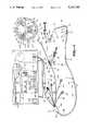
- FIG. 1is an isometric view of an apparatus for continuously measuring volumetric blood flow incorporating the present invention.
- FIG. 2is a cross sectional view taken along the line 2--2 of FIG. 1.
- FIG. 3is a schematic illustration of a catheter of the present invention disposed within a vessel for obtaining a volumetric flow rate utilizing four transducers on the catheter.
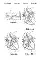
- FIGS. 4A, 4B and 4Care cross sectional views of a human heart showing three different positions of the catheter of the present invention in the pulmonary artery of the heart.
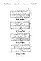
- FIGS. 5A, 5B, 5C and 5Dare schematic illustrations of various transducer arrangements on a catheter of the present invention.
- FIG. 6is a plan view of an alternative embodiment of an ultrasonic pulmonary artery catheter which incorporates the present invention and eliminates the need for a movable guide wire.
- FIG. 7is an enlarged detail view of the fixed wire used in the catheter shown in FIG. 6.
- the apparatusis for measuring volumetric flow of liquid in a vessel which has a wall and an axis extending longitudinally of the vessel parallel to the vessel wall.
- a flexible catheterwhich has a longitudinal axis is provided and is adapted to be disposed in the vessel.
- First, second and third ultrasonic transducersare carried by the catheter on one side of the catheter and are spaced apart longitudinally of the catheter.
- the second and third transducersare spaced apart a predetermined distance.
- the first and second transducerscomprise one set of transducers and the first and third transducers comprising another set of transducers.
- Instrumentation meansis provided which is connected to the first, second and third transducers for causing them to emit ultrasonic energy beams therefrom.
- the first of the ultrasonic transducersis positioned on the catheter to emit an ultrasonic energy beam at an angle with respect to the longitudinal axis of the catheter and the second and third transducers are positioned on the catheter to emit ultrasonic beams extending generally perpendicular to the longitudinal axis of the catheter.
- the instrumentation means providedincludes means connecting the first, second and third transducers whereby the first transducer measures the velocity profile of the flow of the liquid in the vessel by Doppler shift measurements and the second and third transducers are used for measuring the velocity profile of the flow of the liquid in the vessel by Doppler shift measurements and at least a portion of the diameter of the vessel at the location that the transducer is positioned on the catheter.
- the instrumentation meansalso includes means for ascertaining which of the first and second sets, or all, of ultrasonic transducers provides the optimal velocity profile and diameter measurements.
- the instrumentation meansalso includes means for sensing an error condition when an optimal measurement is not available from the catheter as it is positioned.
- FIG. 1the apparatus and method for continuously measuring volumetric blood flow using multiple transducers is shown in FIG. 1.
- the apparatusconsists of a control console 11 and a catheter 12 which is connected to the control console 11.
- the catheter 12consists of a flexible elongate member 13 formed of suitable material such as plastic.
- a cross-sectional view of the elongate member 13is shown in FIG. 2 and as shown therein, the flexible elongate member 13 is provided with a plurality of lumens 16, 17, 18, 19, 21, 22 and 23 for a total of 7 lumens. As shown, the lumens are of various sizes and perform different functions.
- lumen 16is utilized for providing pressure monitoring, also serves as a possible injectate lumen and it accommodates the front distal, intermediate and proximal transducers T4, T2 and T1.
- Lumen 17is provided for the wires 24, 26, 27, 28 and 30a and 30b for the front proximal, intermediate and distal transducers T4, T2 and T1 respectively.
- Lumen 18is provided for the thermistor and the thermistor wires 31 and 32.
- Lumen 19is utilized for providing pressure monitoring and serves as a possible injectate lumen.
- Lumen 21is provided for a guide wire 29 and also serves as a balloon inflation and deflation lumen.
- Lumen 22is used to provide pressure monitoring and also serves as a possible injectate lumen.
- Lumen 22generally indicates right ventricular or main pulmonary artery pressure.
- Lumen 23accommodates the wires 33 and 34 for the back transducer T3.
- lumen 16provides right arterial pressure monitoring and serves as an injectate lumen.
- Lumen 19provides distal or pulmonary wedge pressure monitoring.
- Lumen 22provides pressure monitoring in the area of the transducers, so as to indicate their position and serves as an injectate lumen.
- these seven lumenscan be provided in flexible plastic tubing 13 having an outside diameter of 0.098 inches plus or minus 0.003 inches.
- the outside circular wall 36has a minimum thickness of approximately 0.007 inches.
- the septa 37 dividing the lumensshould have minimum thicknesses of approximately 0.004 inches.
- the distal extremity or tip 41 of the elongate member 13is generally U-shaped.
- the flexible elongate member 13is provided with a substantially straight flexible portion 13a having a length of approximately 110 centimeters.
- the U-shaped tip 41 configurationhas a length of approximately 15 centimeters for a total length of 125 centimeters for the elongate member 13.
- the flexible elongate member 13is provided with another relatively straight portion 13b extending beyond an approximately 90° bend 43. It also is provided with another generally straight portion 13c extending beyond a more gently curved approximately 60° bend 44.
- An inflatable flotation balloon 46is mounted on the distal extremity of the portion 13c by suitable means such as an adhesive.
- the balloonis formed of a suitable material such as latex and can be inflated and deflated by a fluid passing through an inflation and deflation port 47 which is in communication with the balloon inflation lumen 21.
- the balloon 46will take a generally spherical configuration as shown in dotted lines when inflated and can be inflated to a suitable diameter as, for example, 10 to 14 millimeters.
- the portion 13cextends through the balloon and is provided with a distal pressure port 48 which is in communication with the lumen 19.
- a thermistor 51 of a conventional constructionis mounted in the portion 13c proximal of the balloon 46 intermediate of the bend 44 and the balloon 46. It is mounted in the space occupied by the lumen 18.
- the thermistor 51is connected to conductors 31 and 32 which extend through the lumen 18.
- Additional portsare provided in the catheter 12 and include a positioning port 54 which is in communication with the lumen 22 and a right atrial pressure port and injectate port 56 which is in communication with the lumen 16. Both of the ports 54 and 56 are located near the distal extremity of the flexible elongate member 13 with the port 54 being located from 1 to 3 centimeters from the proximal end of the bend 43 and the port 56 being located approximately 18 centimeters from the port 54.
- the proximal extremity of the elongate member 13is connected to a plurality of fittings through a manifold molding 96 as shown in FIG. 1.
- an elongate flexible member 61which is provided with a Luer-type fitting 62.
- the flexible elongate tubular member 61is connected to the right atrial pressure lumen 16.
- Another elongate flexible tubular member 63is provided with a Luer-type fitting 64 and is connected to the distal pressure lumen 19.
- Another flexible elongate member 66is connected to the balloon inflation lumen 21.
- a two arm adapter 67is mounted on the tubular member 66 that is connected to a stop cock 71 which is provided with a handle 72 and a Luer-type fitting 73.
- a syringe 74 of a conventional typeis provided which carries a fluid of a suitable type such as carbon dioxide which can be used for inflating and deflating the balloon 46.
- the adapter 67is also provided with a
- the guide wire 29serves as a positioning and straightening device and extends through the lumen 21 and has a suitable diameter such as 0.012 inches.
- the guide wire 29is formed of a suitable material such as stainless steel and is attached to a relatively straight piece of hypodermic tube 79 having a suitable diameter such as 0.042 inches and is also formed of a suitable material such as stainless steel.
- the tube 79has a length such that it extends approximately the entire length of the flexible elongate member 66.
- a knob 81is secured to the proximal extremity of the tube 79 and is used for advancing and retracting the guide wire 29.
- the guide wire 29has a length so that when the knob is pushed forward into the central arm 76, the guide wire 29 extends through to the distal extremity or tip 41 of the catheter 12 to substantially straighten the same to facilitate insertion of the catheter 12 into the vessel of the human body and also to facilitate advancement of the same as the inflated balloon 46 is utilized to advance the catheter as hereinafter described.
- a raised section such as solder joint or other means 82 on the tube 79serves as a stop to prevent retraction of the tube 79 through a removable cap 83 carried by the central arm 76.
- the proximal extremity of the wire 29 and the tube 79are joined together by conventional means such as solder or by crimping.
- Another flexible elongate element 86 with a Luer-type fitting 87is provided which is in communication with the positioning pressure lumen 22.
- Another flexible elongate tubular member 88is in communication with the lumen 18. It is provided with a thermodilution connector 89 of a conventional type.
- Another flexible elongate member 91is provided which has wires extending therethrough which are connected to the back transducer provided in the lumen 23 and the front transducer wires provided in lumen 17.
- the elongate member 91is connected to a connector 92 which is connected to all of the wires extending through the elongate member 91.
- a manifold molding 96is provided around the proximal extremity of the flexible elongate member 13 and the distal extremities of the flexible elongate members 61, 63, 66, 86, 88 and 91.
- a strain relief and reinforcing member 97 formed of a suitable material such as rubberextends out of the molding 96 and covers the proximal extremity 42 of the flexible elongate element 13.
- the connector 92plugs into its corresponding connector 101 which is at the end of cable 102 that extends into the front panel 103 of the control console 11.
- the control consoleincludes a knob 104 provided on the front panel 103 which can be utilized for setting the alarm settings of the cardiac output limits and the diameter limits of the apparatus.
- a "power on” push button 106is provided as well as an alarm muting push button 107.
- push buttons 108 and 109can be provided for setting “alarm on”, and “high” and “low” alarm limits for the cardiac output.
- push buttons 111 and 112can be provided for setting “alarm on", and "low” and “high” alarm limits for the diameter measurement.
- a graphic display 116is provided for displaying instantaneous flow waveforms, flow trends or velocity profiles.
- Mode push buttons 117are provided for selecting either a "monitor” or “insert” mode.
- a digital readout 118is provided for displaying the cardiac output in liters per minute with push buttons 119 and 121 giving the capabilities to provide the mean cardiac and the peak cardiac outputs.
- a digital display 122is provided for giving a readout of measured parameters such as the diameter of the vessel being monitored in millimeters, stroke volume or a cardiac index.
- Vertical LCD bars display 123is provided adjacent the display 116.
- the bars display 123by their heights give an indication of the validity of the acoustic information being processed by the control console 11 and thereby give an indication of the efficacy of position of the catheter in making correct velocity and volumetric flow measurements in the vessel in which it is positioned.
- At least four ultrasonic transducersare carried by the catheter 12.
- Front and back transducersare provided as hereinafter described.
- the front transducerstypically are mounted within the recess provided by the lumen 16 whereas the back transducers are provided in the lumen 23 which is diametrically opposite the lumen 16.
- the distal extremity bends 43 and 44are formed within the plane which includes the longitudinal axis of the catheter 12 and a line passing diametrically through the catheter and through the middle of the front and back transducer lumens 16 and 23 respectively.
- transducer beamsThis is necessary to orient the transducer beams such that each lies substantially within a single plane which includes the longitudinal axis of the main pulmonary artery when the catheter's distal extremity 13c is positioned downstream in one of the smaller branches of the right pulmonary artery.
- This beam positioningis essential to obtain accurate diameter and velocity profile measurements for calculating volumetric blood flow or cardiac output.
- the catheter 12is shown positioned within a human heart.
- the introduction of the catheter 12 through the jugular vein of the patientis a technique which is generally well known to those skilled in the art.
- the guide wire 29is advanced to its extreme distal position by operation of the knob 81 to straighten the distal extremity or tip 41 of the catheter 12 to facilitate introduction of the catheter into the jugular vein of the patient.
- 4A, 4B and 4Cpasses into the heart 161 through the venous port 162 of the superior vena cavae 163, through the right atrium 164, and then through the tricuspid valve 166, the right ventricle 167, through the pulmonary valve 168, through the main pulmonary artery 169 and into the right pulmonary artery branch 171 and then wedging downstream in one of the secondary branches leading from the right pulmonary artery branch with the tip of the catheter having the balloon thereon being disposed in that branch.
- its locationcan be monitored by observing the pressure waveforms which are quite distinct from one another in the different parts of the circulatory system. Adequate velocity and diameter determinations can generally be made with the transducers positioned in the region between pulmonic valve 168 and below bifurcation 172.
- first, second and fourth ultrasonic transducers T1, T2 and T4are carried by the catheter on the front side of the catheter and are spaced longitudinally of the catheter 12.
- the second and fourth transducers or, in other words, the transducers T2 and T4are spaced apart a predetermined distance.
- a third transducer T3is provided on the back side of the catheter 12 opposite the transducers T1, T2 and T4 and faces in a direction which is 180° opposed to the direction in which the transducers T2 and T4 face.
- the transducer T3may not be necessary when the catheter is immediately adjacent a wall of the vessel.
- the first and second transducers, transducers T1 and T2serve as one set of transducers in conjunction with the third transducer T3 and the first and fourth transducers T1 and T4 form another set of transducers in conjunction with the third transducer T3.
- the control console 11serves to supply electrical signals to the transducers through the connecting wires hereinbefore described to cause the transducers to emit ultrasonic energy beams as indicated by the rays B1, B2, B3 and B4 shown in FIG. 3.
- the first ultrasonic transducer T1is positioned on the catheter so that it emits an ultrasonic energy beam B1 which is at an angle ⁇ 1 with respect to the longitudinal axis of the catheter 12.
- the transducers T2, T3 and T4emit ultrasonic beams B2, B3 and B4 at angles ⁇ 2, ⁇ 3 and ⁇ 4 which are generally perpendicular to the longitudinal axis of the catheter 12.
- the beams B2, B3 and B4are directed at angles which are substantially 90° with respect to the longitudinal axis of the catheter 12.
- the beam B3is directed in a direction which is 180° or opposite to that of the beams B2 and B4.
- the first transducer T1measures the velocity profile of the liquid in the vessel 181 by Doppler shift measurements.
- the second and fourth transducers T2 and T4are also used for measuring the velocity profile of the flow of the liquid in the vessel by Doppler shift measurements and at least a portion of the diameter of the vessel at the location that the transducer is positioned on the catheter.
- the third transducer T3measures at least a portion of the diameter of the vessel at the location that the transducer is positioned on the catheter.
- the instrumentation means provided by the control console 11also includes means for ascertaining which of the first and second sets, or all, of ultrasonic transducers provides optimal velocity profile and diameter measurements.
- the catheter 12In the position of the catheter 12, shown in FIG. 4A, the catheter 12 either because of the vasculature of the heart or the longitudinal position of the catheter in the pulmonary artery or vessel in the heart has both of the transducers T2 and T4 on the front side of the catheter in good positions to receive the desired information to provide accurate velocity and volumetric blood flow through the vessel.
- the transducers T2 and T4are both in optimum positions within the pulmonary artery to make accurate measurements.
- instrumentation 11will use either transducers T1, T2, and T3 as a set, or transducers T1, T4, and T3 as a set. Or, it may use all four transducers T1, T2, T3, and T4 as a set.
- FIG. 4BIn the position of the catheter 12, as shown in FIG. 4B, there is depicted a situation in which the pulmonary artery is too short in comparison to the spacing between the catheter transducers T2 and T4 or the catheter 12 is somewhat proximal to the position where it should be located because the transducer T4 is in a region of or below the pulmonic valve 168 in the heart. For that reason the information supplied by the transducer T4 is inaccurate or inappropriate. However, the transducer T2 is still in a good position and therefore the instrumentation 11 will ascertain that this information is appropriate information and will supply the appropriate measurements utilizing transducers T1, T2 and T3 as the set of transducers, rather than the transducers T1, T4 and T3 as the set of transducers.
- FIG. 4Cthere is depicted a situation in which the transducer T2 may not provide good information with the situation being that the catheter 12 has been pushed too far distally or the pulmonary artery is quite long in comparison to the spacing between the transducers T2 and T4.
- the instrumentation 11will select the transducers T1, T3 and T4 as being the transducers to be utilized rather than the transducers T1, T2 and T3.
- the diameter transducersare used two at a time to measure diameter when the catheter 12 is not immediately adjacent a wall of the vessel. Thus, either T2 and T3 or T3 and T4 are used to measure the diameter of the vessel.
- the position of the catheter 12is much less position dependent and thus will give a range of accurate readings in a wider range along the longitudinal axis of the catheter 12 than would be possible with a single transducer such as transducer T2 or transducer T4.
- the fourth transducer T4rather than being a diameter transducer can be positioned at an angle similar to transducer T1 to be a velocity transducer (see FIG. 5A). This would make it possible to select either of the velocity transducers T1 or T4 using always the two diameter transducers T2 and T3.
- the fourth transducer T4rather than being primarily a diameter transducer is instead a velocity transducer similar to T1, its beam direction can be opposite to that of T1. That is if beam Bl points upstream, beam B4 would point downstream, as in FIG. 5B.
- transducers T1, T2, T3 and T4can be in other orders and directions, depending on the algorithms used to analyze the velocity and diameter information and perform the flow calculations.
- T1, T3 and T4could be primarily for diameters measurements, with T2 being used for velocity measurements (see FIG. 5C).
- T3 and T4could be used primarily for diameter measurements with T1 and T2 being for velocity measurements (See FIG. 5D).
- a pressure porthas been located adjacent to the transducers and this pressure port has been utilized as a key for positioning the catheter.
- this pressure portis merely used as a reference point when the positioning of the catheter has been accomplished more effectively by utilizing error criteria to determine the proper position of the catheter.
- Thiscan be readily accomplished by utilizing error criteria in an algorithm incorporated into software implemented within the control console 11 to establish whether or not the diameter and the velocity signals being received are in fact accurate measurements. Appropriate data would be incorporated into the algorithm by channeling the algorithm.
- the control console 11can be utilized to detect errors in the input signals. Utilizing such information, appropriate instructions can be provided on the control console 11 to facilitate positioning of the catheter 12 in the vessel. For example, instructions can be given to advance or retract the catheter to improve the signals being received.
- FIGS. 6 and 7.Such a catheter 201 is shown in FIGS. 6 and 7.
- the catheter 201 shown thereinis adapted to be substituted for the catheter 12 and is adapted to be connected to the control console 11 shown in FIG. 1.
- This catheter 201in many respects is very similar to the catheter 12 shown in FIG. 1 with the exception that the guidewire 79 utilized in the catheter assembly shown in FIG. 1 is eliminated. Also a gentle substantially J-shaped bend is provided in the distal extremity of the catheter 201 rather than the generally U-shaped bend provided in FIG. 1.
- the catheter 201 shown in FIG. 6consists of a flexible elongate member 202 formed of plastic.
- a cross section like FIG. 2 taken of the flexible elongate member in the position shown in FIG. 1would provide a similar cross section in which a total of seven lumens are provided in the flexible elongate member 202.
- the flexible elongate member 202is provided with a relatively straight flexible portion 202a having a suitable length as for example approximately 110 cm up to a bend 203 of approximately 15° to 20° after which there is provided another flexible relatively straight portion 202b up to a bend 204 of another small angle as for example 15° to 20° after which there is provided another flexible relatively straight portion 202c extending to the distal extremity of the catheter 201.
- the bend 203forms an angle of approximately 165° to 160°
- bend 204forms an angle of approximately 165° to 160°.
- the bend 203 and 204 in the distal extremity of the catheter 201provide a very gentle curvature which represents a substantially modified J-bend.
- An inflatable latex balloon 206is provided on the distal extremity of the flexible elongate member 202 and is adapted to be inflated and deflated through a port 207.
- a thermistor 211is mounted in the portion 202c adjacent the bend 204.
- Transistors T1, T2, and T4are mounted on the front side of the flexible elongate member 202 proximal of the bend 203 and the transistor T3 is provided on the backside of the member 202 opposite and between the transducers T2 and T4.
- the four transducerscan be arranged in any of the manners heretofore described.
- a main pulmonary artery port 212is provided in the flexible elongate member 202 slightly proximal of the transistor T4 and a right atrial port 213 is provided proximal of the port 212.
- Markers 216 visible to the human eye of a conventional typeare provided on the exterior surface of the flexible elongate member 202 and are spaced longitudinally thereof. The markers 216 serve to indicate to the surgeon how far the catheter 201 has been introduced into the patient.
- the proximal extremity of the flexible elongate member 202is connected through a manifold 221 to a plurality of flexible elongate members 222, 223, 224, 226, 227 and 228.
- the flexible elongate member 222is connected to the distal pressure lumen and is provided with a Luer adapter 231 at its proximal extremity.
- the flexible elongate member 223carries the conductors provided in the flexible elongate member 202 connected to the devices in the catheter.
- the conductors in the elongate member 223are connected to an electrical connector 232 at the proximal extremity of the flexible elongate member 223.
- the flexible elongate member 224is provided with a Luer adapter 233 at its proximal extremity.
- the flexible elongate member 226is provided with an electrical connector 234 adapted to be connected to a conventional thermodilution console (not shown).
- the flexible elongate member 227is connected to the balloon inflation lumen and is provided with a stop cock 236 which is secured to the flexible elongate member 227 with an adapter 237.
- the stop cock 236is provided with a Luer type fitting 238 and a handle 239.
- the flexible elongate member 228is connected to the right atrial pressure lumen and is provided with a Luer adapter 240.
- Suitable meansis provided for giving additional stiffness to the flexible elongate member 202 which is just short of the pre-formed bend 203 to provide support and additional rigidity to the catheter throughout substantially its entire length except in the region of the pre-formed bend 203 and beyond to the distal extremity of the catheter.
- the predetermined bends 203 and 204have been provided in the flexible elongate member 202 to provide stability for the catheter 201 when the catheter 201 is positioned in the pulmonary artery.
- One means for providing this additional rigidity and stiffness in the flexible elongate member 202is obtained by utilizing a flexible elongate element 241 in the form of a wire of a suitable material such as stainless steel.
- the wire 241has a length so that it extends substantially the entire length of the flexible elongate member 202. Its proximal extremity 241a has a suitable diameter such as 0.014" which diameter continues for a suitable distance as for example 70 cm.
- the wire 241is ten taper ground to a diameter of 0.012" to provide a portion 241b that extends for approximately 20 additional centimeters. Another tape grind then reduces the diameter of the wire 241 to 0.009" to provide a portion 241c which extends for approximately another 20 centimeters to a region adjacent the transducers a portion 241d is provided on the wire 241 which has a larger diameter of 0.014" for a distance of 2 to 3 centimeters.
- the wire portion 241dserves to provide increased stiffness in the region of the catheter 201.
- the distal extremity of the wire 241is provided with a portion 241e which has a continuous taper in which the diameter of the wire is reduced from 0.014" to 0.0025" to give additional flexibility to the distal extremity of the wire 241.
- a coil spring 242is mounted on the wire 241 by having the tapered portion 241e extend into the coil 242 and be secured thereto by suitable means such as solder.
- the spring 242is formed of a suitable material such as 0.002" diameter stainless steel wire.
- the springhas a suitable outside diameter as for example 0.014" and a length of approximately 2 cm.
- wire 241 with the spring 242is positioned so that spring 242 is just short of the bend 203. This makes it possible for the distal extremity of the catheter 11 to have good flexibility so that it can be floated into the desired position upon inflation of the balloon 206. At the same time, wire 241 provides additional rigidity to the catheter 201 to facilitate its insertion into the vessel of the patient.
- the proximate extremity of the wire 241is provided with a right angle hook portion 241f which is positioned in a hole 244 in the adapter 237 and is retained therein by the stopcock 236 (see FIG. 7).
- the use of the catheter 201 in the volumetric flow measuring apparatus shown in FIG. 1is very similar to that hereinbefore described in conjunction with the apparatus shown in FIG. 1.
- the catheter 201makes the catheter less position dependent because the elimination of the movable wire removes another variable in the positioning of the catheter in a desired position within the heart of the patient. This is true because after removal of the movable wire from the distal extremity of the catheter, the distal extremity of the catheter has a different flexibility than when the guidewire was positioned in the distal extremity making it more difficult for the instrumentation 11 to ascertain whether or not the catheter 12 has been properly positioned in the heart.
- the fixed wire 241provides additional rigidity throughout the remainder of the catheter while providing the desired transitions in flexibility in the regions leading up to the portions of the catheter carrying the transducers T1, T2, T3 and T4 while still providing the desired rigidity within the catheter at that region.
- the spring 242provides graduated transition at the distal extremity of the wire 241 and provides a relatively blunt end so that the wire 241 will not puncture the flexible elongate element 202. Alternatively if desired the spring 242 can be eliminated and a blunt end can be formed on the end of the wire 241 for a similar purpose.
- the relatively small angle preformed bends 203 and 204 provided in the distal extremity of the catheter 201make it possible for the catheter 201 to negotiate the vessels of the patient and make it possible to facilitate positioning the distal extremity of the catheter in the appropriate position in the heart to thereby properly position the transducers T1 through T4.
- the bends 203 and 204also provide the necessary stability for the distal extremity of the catheter during the time that measurements are being made by the instrumentation console 11 from information supplied by the transducers T1 through T4.
- the catheterwhich is shown in FIGS. 6 and 7 can be utilized in the volumetric flow measuring apparatus and method heretofore described to provide a less position dependent apparatus and method.
- the elimination of the movable wireeliminates one additional variable from the system. This makes it possible to more accurately predict when the catheter has been properly positioned in the heart to make accurate volumetric flow measurements.
Landscapes
- Health & Medical Sciences (AREA)
- Life Sciences & Earth Sciences (AREA)
- Physics & Mathematics (AREA)
- Molecular Biology (AREA)
- Animal Behavior & Ethology (AREA)
- Veterinary Medicine (AREA)
- Pathology (AREA)
- Public Health (AREA)
- Engineering & Computer Science (AREA)
- Biomedical Technology (AREA)
- Heart & Thoracic Surgery (AREA)
- Medical Informatics (AREA)
- General Health & Medical Sciences (AREA)
- Surgery (AREA)
- Biophysics (AREA)
- Radiology & Medical Imaging (AREA)
- Nuclear Medicine, Radiotherapy & Molecular Imaging (AREA)
- Hematology (AREA)
- General Physics & Mathematics (AREA)
- Cardiology (AREA)
- Physiology (AREA)
- Electromagnetism (AREA)
- Fluid Mechanics (AREA)
- Ultra Sonic Daignosis Equipment (AREA)
- Media Introduction/Drainage Providing Device (AREA)
- Measuring Pulse, Heart Rate, Blood Pressure Or Blood Flow (AREA)
Abstract
Description
Claims (22)
Priority Applications (4)
| Application Number | Priority Date | Filing Date | Title |
|---|---|---|---|
| US07/581,012US5121749A (en) | 1988-10-05 | 1990-09-12 | Position in dependent volumetric flow measuring apparatus |
| CA 2051152CA2051152A1 (en) | 1990-09-12 | 1991-09-11 | Less position dependent volumetric flow measuring apparatus, catheter for use therein, and method |
| JP23334791AJPH05146439A (en) | 1990-09-12 | 1991-09-12 | Flow rate measuring device which is less affected by location, and catheter used for said flow rate measuring device, and flow rate measuring method, and catheter introducing method |
| EP19910308363EP0475773A1 (en) | 1990-09-12 | 1991-09-12 | Less position dependent volumetric flow measuring apparatus, catheter for use therein, and method |
Applications Claiming Priority (2)
| Application Number | Priority Date | Filing Date | Title |
|---|---|---|---|
| US07/254,317US4947852A (en) | 1988-10-05 | 1988-10-05 | Apparatus and method for continuously measuring volumetric blood flow using multiple transducer and catheter for use therewith |
| US07/581,012US5121749A (en) | 1988-10-05 | 1990-09-12 | Position in dependent volumetric flow measuring apparatus |
Related Parent Applications (1)
| Application Number | Title | Priority Date | Filing Date |
|---|---|---|---|
| US07/254,317Continuation-In-PartUS4947852A (en) | 1988-10-05 | 1988-10-05 | Apparatus and method for continuously measuring volumetric blood flow using multiple transducer and catheter for use therewith |
Publications (1)
| Publication Number | Publication Date |
|---|---|
| US5121749Atrue US5121749A (en) | 1992-06-16 |
Family
ID=24323551
Family Applications (1)
| Application Number | Title | Priority Date | Filing Date |
|---|---|---|---|
| US07/581,012Expired - Fee RelatedUS5121749A (en) | 1988-10-05 | 1990-09-12 | Position in dependent volumetric flow measuring apparatus |
Country Status (4)
| Country | Link |
|---|---|
| US (1) | US5121749A (en) |
| EP (1) | EP0475773A1 (en) |
| JP (1) | JPH05146439A (en) |
| CA (1) | CA2051152A1 (en) |
Cited By (35)
| Publication number | Priority date | Publication date | Assignee | Title |
|---|---|---|---|---|
| US5174299A (en)* | 1991-08-12 | 1992-12-29 | Cardiac Pacemakers, Inc. | Thermocouple-based blood flow sensor |
| US5207226A (en)* | 1991-01-25 | 1993-05-04 | Regents Of The University Of Minnesota | Device and method for measurement of blood flow |
| WO1993017624A1 (en)* | 1992-03-13 | 1993-09-16 | Cardiometrics, Inc. | Vascular catheter for measuring flow characteristics and method |
| US5284146A (en)* | 1991-06-03 | 1994-02-08 | Applied Biometrics Inc. | Removable implanted device |
| US5335663A (en)* | 1992-12-11 | 1994-08-09 | Tetrad Corporation | Laparoscopic probes and probe sheaths useful in ultrasonic imaging applications |
| US5339816A (en)* | 1991-10-23 | 1994-08-23 | Aloka Co., Ltd. | Ultrasonic doppler blood flow monitoring system |
| WO1995009565A1 (en)* | 1993-10-06 | 1995-04-13 | Cardiovascular Imaging Systems, Inc. | Pre-filled imaging catheter |
| US5439003A (en)* | 1993-12-16 | 1995-08-08 | Modern Technologies Corp. | Apparatus and method for measuring fluid flow |
| US5443074A (en)* | 1992-01-21 | 1995-08-22 | Baxter International Inc. | Dual port thermodilution catheter and method for manufacture |
| US5588438A (en)* | 1991-01-29 | 1996-12-31 | Interflo Medical, Inc. | System and method for controlling the temperature of a catheter-mounted heater |
| US5595182A (en)* | 1994-10-24 | 1997-01-21 | Transonic Systems, Inc. | Cardiovascular measurements by sound velocity dilution |
| US5655537A (en)* | 1994-11-30 | 1997-08-12 | Boston Scientific Corporation | Acoustic imaging and doppler catheters and guidewires |
| US5720293A (en)* | 1991-01-29 | 1998-02-24 | Baxter International Inc. | Diagnostic catheter with memory |
| US5807269A (en)* | 1991-01-29 | 1998-09-15 | Baxter International Inc. | Thermodilution catheter having a safe, flexible heating element |
| US6435037B1 (en) | 2000-01-06 | 2002-08-20 | Data Sciences International, Inc. | Multiplexed phase detector |
| US20030004456A1 (en)* | 1992-08-13 | 2003-01-02 | Saab Mark A. | Multi-lumen heat transfer catheters |
| US6539316B1 (en) | 2000-01-06 | 2003-03-25 | Data Sciences International, Inc. | Phase detector |
| US6585660B2 (en) | 2001-05-18 | 2003-07-01 | Jomed Inc. | Signal conditioning device for interfacing intravascular sensors having varying operational characteristics to a physiology monitor |
| US6595071B1 (en) | 2000-01-06 | 2003-07-22 | Transoma Medical, Inc. | Estimation of error angle in ultrasound flow measurement |
| US20030167023A1 (en)* | 1997-05-01 | 2003-09-04 | Frederick J. Bennett | Ultrasound catheter for providing a therapeutic effect to a vessel of a body |
| US20030216621A1 (en)* | 2002-05-20 | 2003-11-20 | Jomed N.V. | Multipurpose host system for invasive cardiovascular diagnostic measurement acquisition and display |
| US6663570B2 (en) | 2002-02-27 | 2003-12-16 | Volcano Therapeutics, Inc. | Connector for interfacing intravascular sensors to a physiology monitor |
| US20050171446A1 (en)* | 1999-02-02 | 2005-08-04 | Transonic Systems, Inc | Method and apparatus for determining a blood flow during a vascular access dysfunction corrective procedure |
| US7976483B2 (en) | 1997-05-01 | 2011-07-12 | Ekos Corporation | Ultrasound assembly with increased efficacy |
| US20120245457A1 (en)* | 2011-03-25 | 2012-09-27 | Crowley Robert J | Ultrasound imaging catheters and guidewires with non-interfering and coordinated position and orientation sensors |
| US9320493B2 (en) | 2014-07-08 | 2016-04-26 | Nadarasa Visveshwara | System and method for measuring fluidics in arteries |
| US10656025B2 (en) | 2015-06-10 | 2020-05-19 | Ekos Corporation | Ultrasound catheter |
| US10888232B2 (en) | 2011-08-20 | 2021-01-12 | Philips Image Guided Therapy Corporation | Devices, systems, and methods for assessing a vessel |
| US10926074B2 (en) | 2001-12-03 | 2021-02-23 | Ekos Corporation | Catheter with multiple ultrasound radiating members |
| US11122980B2 (en) | 2011-08-20 | 2021-09-21 | Imperial College Of Science, Technology And Medicine | Devices, systems, and methods for visually depicting a vessel and evaluating treatment options |
| CN114964066A (en)* | 2022-08-02 | 2022-08-30 | 深圳市海清视讯科技有限公司 | Measuring device and screening system |
| US11672553B2 (en) | 2007-06-22 | 2023-06-13 | Ekos Corporation | Method and apparatus for treatment of intracranial hemorrhages |
| US11918795B2 (en) | 2019-05-01 | 2024-03-05 | Bard Access Systems, Inc. | Puncturing devices, puncturing systems including the puncturing devices, and methods thereof |
| US11925367B2 (en) | 2007-01-08 | 2024-03-12 | Ekos Corporation | Power parameters for ultrasonic catheter |
| WO2024206179A1 (en)* | 2023-03-24 | 2024-10-03 | Edwards Lifesciences Corporation | Systems and methods for determining flow and cardiac output |
Families Citing this family (2)
| Publication number | Priority date | Publication date | Assignee | Title |
|---|---|---|---|---|
| DE69519516T2 (en) | 1995-06-29 | 2001-06-13 | Schneider (Europe) Gmbh, Buelach | Medical device for measuring pressure in a blood vessel |
| US9380992B2 (en)* | 2007-03-30 | 2016-07-05 | General Electric Company | Method and apparatus for measuring flow in multi-dimensional ultrasound |
Citations (3)
| Publication number | Priority date | Publication date | Assignee | Title |
|---|---|---|---|---|
| US4721115A (en)* | 1986-02-27 | 1988-01-26 | Cardiac Pacemakers, Inc. | Diagnostic catheter for monitoring cardiac output |
| US4869263A (en)* | 1988-02-04 | 1989-09-26 | Cardiometrics, Inc. | Device and method for measuring volumetric blood flow in a vessel |
| US4947852A (en)* | 1988-10-05 | 1990-08-14 | Cardiometrics, Inc. | Apparatus and method for continuously measuring volumetric blood flow using multiple transducer and catheter for use therewith |
Family Cites Families (3)
| Publication number | Priority date | Publication date | Assignee | Title |
|---|---|---|---|---|
| US4637401A (en)* | 1984-11-01 | 1987-01-20 | Johnston G Gilbert | Volumetric flow rate determination in conduits not directly accessible |
| US4674336A (en)* | 1984-11-01 | 1987-06-23 | Johnston G Gilbert | Volumetric flow rate determination in conduits not directly accessible |
| DE3639321A1 (en)* | 1985-12-18 | 1987-08-06 | Karl Dr Wernecke | Angiographic catheter set having a sound microprobe for the sonographic visualisation of vessels |
- 1990
- 1990-09-12USUS07/581,012patent/US5121749A/ennot_activeExpired - Fee Related
- 1991
- 1991-09-11CACA 2051152patent/CA2051152A1/ennot_activeAbandoned
- 1991-09-12EPEP19910308363patent/EP0475773A1/ennot_activeWithdrawn
- 1991-09-12JPJP23334791Apatent/JPH05146439A/enactivePending
Patent Citations (3)
| Publication number | Priority date | Publication date | Assignee | Title |
|---|---|---|---|---|
| US4721115A (en)* | 1986-02-27 | 1988-01-26 | Cardiac Pacemakers, Inc. | Diagnostic catheter for monitoring cardiac output |
| US4869263A (en)* | 1988-02-04 | 1989-09-26 | Cardiometrics, Inc. | Device and method for measuring volumetric blood flow in a vessel |
| US4947852A (en)* | 1988-10-05 | 1990-08-14 | Cardiometrics, Inc. | Apparatus and method for continuously measuring volumetric blood flow using multiple transducer and catheter for use therewith |
Cited By (62)
| Publication number | Priority date | Publication date | Assignee | Title |
|---|---|---|---|---|
| US5207226A (en)* | 1991-01-25 | 1993-05-04 | Regents Of The University Of Minnesota | Device and method for measurement of blood flow |
| US5588438A (en)* | 1991-01-29 | 1996-12-31 | Interflo Medical, Inc. | System and method for controlling the temperature of a catheter-mounted heater |
| US5857976A (en)* | 1991-01-29 | 1999-01-12 | Baxter International Inc. | Thermodilution catheter having a safe, flexible heating element |
| US5807269A (en)* | 1991-01-29 | 1998-09-15 | Baxter International Inc. | Thermodilution catheter having a safe, flexible heating element |
| US6355001B1 (en) | 1991-01-29 | 2002-03-12 | Edwards Lifesciences Corporation | Thermodilution catheter method using a safe, flexible heating element |
| US7254946B1 (en) | 1991-01-29 | 2007-08-14 | Edwards Lifesciences Corporation | Thermodilution catheter having a safe, flexible heating element |
| US6387052B1 (en) | 1991-01-29 | 2002-05-14 | Edwards Lifesciences Corporation | Thermodilution catheter having a safe, flexible heating element |
| US5720293A (en)* | 1991-01-29 | 1998-02-24 | Baxter International Inc. | Diagnostic catheter with memory |
| US5284146A (en)* | 1991-06-03 | 1994-02-08 | Applied Biometrics Inc. | Removable implanted device |
| US5174299A (en)* | 1991-08-12 | 1992-12-29 | Cardiac Pacemakers, Inc. | Thermocouple-based blood flow sensor |
| US5339816A (en)* | 1991-10-23 | 1994-08-23 | Aloka Co., Ltd. | Ultrasonic doppler blood flow monitoring system |
| US5443074A (en)* | 1992-01-21 | 1995-08-22 | Baxter International Inc. | Dual port thermodilution catheter and method for manufacture |
| US5246007A (en)* | 1992-03-13 | 1993-09-21 | Cardiometrics, Inc. | Vascular catheter for measuring flow characteristics and method |
| WO1993017624A1 (en)* | 1992-03-13 | 1993-09-16 | Cardiometrics, Inc. | Vascular catheter for measuring flow characteristics and method |
| US7811249B2 (en) | 1992-08-13 | 2010-10-12 | Advanced Polymers, Inc. | Multi-lumen heat transfer catheters |
| US6966889B2 (en)* | 1992-08-13 | 2005-11-22 | Saab Mark A | Multi-lumen catheters and methods for using same |
| US20030028212A1 (en)* | 1992-08-13 | 2003-02-06 | Saab Mark A. | Multi-lumen catheters and methods for using same |
| US20030004456A1 (en)* | 1992-08-13 | 2003-01-02 | Saab Mark A. | Multi-lumen heat transfer catheters |
| US20050273145A1 (en)* | 1992-08-13 | 2005-12-08 | Mark Saab | Multi-lumen heat transfer catheters |
| US5437283A (en)* | 1992-12-11 | 1995-08-01 | Tetrad Corporation | Endosurgical ultrasonic probe with integrated biopsy actuator |
| US5335663A (en)* | 1992-12-11 | 1994-08-09 | Tetrad Corporation | Laparoscopic probes and probe sheaths useful in ultrasonic imaging applications |
| WO1995009565A1 (en)* | 1993-10-06 | 1995-04-13 | Cardiovascular Imaging Systems, Inc. | Pre-filled imaging catheter |
| US5421334A (en)* | 1993-10-06 | 1995-06-06 | Cardiovascular Imaging Systems, Inc. | Pre-filled imaging catheter |
| US5724982A (en)* | 1993-12-16 | 1998-03-10 | Modern Technologies Corp. | Apparatus and method for measuring fluid flow |
| US5439003A (en)* | 1993-12-16 | 1995-08-08 | Modern Technologies Corp. | Apparatus and method for measuring fluid flow |
| US5595182A (en)* | 1994-10-24 | 1997-01-21 | Transonic Systems, Inc. | Cardiovascular measurements by sound velocity dilution |
| US6074349A (en)* | 1994-11-30 | 2000-06-13 | Boston Scientific Corporation | Acoustic imaging and doppler catheters and guidewires |
| US5655537A (en)* | 1994-11-30 | 1997-08-12 | Boston Scientific Corporation | Acoustic imaging and doppler catheters and guidewires |
| US20030167023A1 (en)* | 1997-05-01 | 2003-09-04 | Frederick J. Bennett | Ultrasound catheter for providing a therapeutic effect to a vessel of a body |
| US8690818B2 (en) | 1997-05-01 | 2014-04-08 | Ekos Corporation | Ultrasound catheter for providing a therapeutic effect to a vessel of a body |
| US7976483B2 (en) | 1997-05-01 | 2011-07-12 | Ekos Corporation | Ultrasound assembly with increased efficacy |
| US7914509B2 (en) | 1997-05-01 | 2011-03-29 | Ekos Corporation | Ultrasound catheter |
| US20050171446A1 (en)* | 1999-02-02 | 2005-08-04 | Transonic Systems, Inc | Method and apparatus for determining a blood flow during a vascular access dysfunction corrective procedure |
| US6986744B1 (en) | 1999-02-02 | 2006-01-17 | Transonic Systems, Inc. | Method and apparatus for determining blood flow during a vascular corrective procedure |
| US6595071B1 (en) | 2000-01-06 | 2003-07-22 | Transoma Medical, Inc. | Estimation of error angle in ultrasound flow measurement |
| US6539316B1 (en) | 2000-01-06 | 2003-03-25 | Data Sciences International, Inc. | Phase detector |
| US6435037B1 (en) | 2000-01-06 | 2002-08-20 | Data Sciences International, Inc. | Multiplexed phase detector |
| US6585660B2 (en) | 2001-05-18 | 2003-07-01 | Jomed Inc. | Signal conditioning device for interfacing intravascular sensors having varying operational characteristics to a physiology monitor |
| US10926074B2 (en) | 2001-12-03 | 2021-02-23 | Ekos Corporation | Catheter with multiple ultrasound radiating members |
| US20040082866A1 (en)* | 2002-02-27 | 2004-04-29 | Mott Eric V. | Connector for interfacing intravascular sensors to a physiology monitor |
| US7274956B2 (en) | 2002-02-27 | 2007-09-25 | Volcano Corporation | Connector for interfacing intravascular sensors to a physiology monitor |
| US6663570B2 (en) | 2002-02-27 | 2003-12-16 | Volcano Therapeutics, Inc. | Connector for interfacing intravascular sensors to a physiology monitor |
| US20030216621A1 (en)* | 2002-05-20 | 2003-11-20 | Jomed N.V. | Multipurpose host system for invasive cardiovascular diagnostic measurement acquisition and display |
| US20070060822A1 (en)* | 2002-05-20 | 2007-03-15 | Volcano Corp. | Multipurpose host system for invasive cardiovascular diagnostic measurement acquisition and display |
| US7134994B2 (en) | 2002-05-20 | 2006-11-14 | Volcano Corporation | Multipurpose host system for invasive cardiovascular diagnostic measurement acquisition and display |
| US8556820B2 (en) | 2002-05-20 | 2013-10-15 | Volcano Corporation | Multipurpose host system for invasive cardiovascular diagnostic measurement acquisition and display |
| US8562537B2 (en) | 2002-05-20 | 2013-10-22 | Volcano Corporation | Multipurpose host system for invasive cardiovascular diagnostic measurement acquisition and display |
| US8636659B2 (en) | 2002-05-20 | 2014-01-28 | Volcano Corporation | Multipurpose host system for invasive cardiovascular diagnostic measurement acquisition and display |
| US11925367B2 (en) | 2007-01-08 | 2024-03-12 | Ekos Corporation | Power parameters for ultrasonic catheter |
| US11672553B2 (en) | 2007-06-22 | 2023-06-13 | Ekos Corporation | Method and apparatus for treatment of intracranial hemorrhages |
| US20120245457A1 (en)* | 2011-03-25 | 2012-09-27 | Crowley Robert J | Ultrasound imaging catheters and guidewires with non-interfering and coordinated position and orientation sensors |
| US11122980B2 (en) | 2011-08-20 | 2021-09-21 | Imperial College Of Science, Technology And Medicine | Devices, systems, and methods for visually depicting a vessel and evaluating treatment options |
| US10888232B2 (en) | 2011-08-20 | 2021-01-12 | Philips Image Guided Therapy Corporation | Devices, systems, and methods for assessing a vessel |
| US9795359B2 (en) | 2014-07-08 | 2017-10-24 | Nadarasa Visveshwara | System and method for measuring fluidics in arteries |
| US9504443B2 (en)* | 2014-07-08 | 2016-11-29 | Nadarasa Visveshwara | System and method for measuring fluidics in arteries |
| US9320493B2 (en) | 2014-07-08 | 2016-04-26 | Nadarasa Visveshwara | System and method for measuring fluidics in arteries |
| US10656025B2 (en) | 2015-06-10 | 2020-05-19 | Ekos Corporation | Ultrasound catheter |
| US11740138B2 (en) | 2015-06-10 | 2023-08-29 | Ekos Corporation | Ultrasound catheter |
| US11918795B2 (en) | 2019-05-01 | 2024-03-05 | Bard Access Systems, Inc. | Puncturing devices, puncturing systems including the puncturing devices, and methods thereof |
| CN114964066A (en)* | 2022-08-02 | 2022-08-30 | 深圳市海清视讯科技有限公司 | Measuring device and screening system |
| CN114964066B (en)* | 2022-08-02 | 2022-11-25 | 深圳市海清视讯科技有限公司 | Measuring device and screening system |
| WO2024206179A1 (en)* | 2023-03-24 | 2024-10-03 | Edwards Lifesciences Corporation | Systems and methods for determining flow and cardiac output |
Also Published As
| Publication number | Publication date |
|---|---|
| CA2051152A1 (en) | 1992-03-13 |
| JPH05146439A (en) | 1993-06-15 |
| EP0475773A1 (en) | 1992-03-18 |
Similar Documents
| Publication | Publication Date | Title |
|---|---|---|
| US5121749A (en) | Position in dependent volumetric flow measuring apparatus | |
| US4856529A (en) | Ultrasonic pulmonary artery catheter and method | |
| US12029539B2 (en) | Systems, devices, and methods for mapping organ profiles | |
| US11707207B2 (en) | Device, system, and method for assessing intravascular pressure | |
| US11490829B2 (en) | Systems, devices, and methods for mapping organ profiles | |
| US4947852A (en) | Apparatus and method for continuously measuring volumetric blood flow using multiple transducer and catheter for use therewith | |
| EP3020441B1 (en) | Rapid exchange guide unit | |
| US20170360376A1 (en) | Intravascular sensing method and system | |
| US5108369A (en) | Dual-diameter multifunction catheter | |
| US5246007A (en) | Vascular catheter for measuring flow characteristics and method | |
| EP3064127B1 (en) | Device and methods for measuring and treating an anatomical structure | |
| US8632469B2 (en) | Devices, systems, and methods for mapping organ profiles | |
| US5144955A (en) | Doppler velocity measuring medical unit | |
| US11006840B2 (en) | Device, system, and method for assessing intravascular pressure | |
| US20150157216A1 (en) | Device, system, and method for assessing intravascular pressure | |
| US20150173629A1 (en) | Device, system, and method for assessing intravascular pressure | |
| KR20100127815A (en) | Pressure sensitive catheter | |
| CA2734698A1 (en) | Physiological sensor delivery device and method | |
| JP2012501807A5 (en) | ||
| HK40041737B (en) | Assessment of a vessel | |
| HK40041737A (en) | Assessment of a vessel | |
| HK1225939B (en) | Device and methods for measuring and treating an anatomical structure |
Legal Events
| Date | Code | Title | Description |
|---|---|---|---|
| AS | Assignment | Owner name:CARDIOMETRICS, INC., MOUNTAIN VIEW, CA A CORP. OF Free format text:ASSIGNMENT OF ASSIGNORS INTEREST.;ASSIGNORS:NASSI, MENAHEM F.;FRISBIE, JEFFREY S.;LEVY, STANLEY JR.;REEL/FRAME:005440/0778 Effective date:19900830 | |
| AS | Assignment | Owner name:SILICON VALLEY BANK, CALIFORNIA Free format text:ASSIGNMENT OF ASSIGNORS INTEREST;ASSIGNOR:CARDIOMETRICS, INC.;REEL/FRAME:007521/0088 Effective date:19940914 | |
| FPAY | Fee payment | Year of fee payment:4 | |
| AS | Assignment | Owner name:CARDIOMETRICS, INC., CALIFORNIA Free format text:MERGER;ASSIGNOR:CARDIOMETRICS, INC.;REEL/FRAME:007919/0110 Effective date:19951025 Owner name:CARDIOMETRICS, INC., CALIFORNIA Free format text:MERGER;ASSIGNOR:CARDIOMETRICS, INC.;REEL/FRAME:007868/0025 Effective date:19951025 | |
| REMI | Maintenance fee reminder mailed | ||
| LAPS | Lapse for failure to pay maintenance fees | ||
| FP | Lapsed due to failure to pay maintenance fee | Effective date:20000616 | |
| AS | Assignment | Owner name:CARDIOMETRICS INC., CALIFORNIA Free format text:RELEASE;ASSIGNOR:SILICON VALLEY BANK;REEL/FRAME:013542/0210 Effective date:20021126 | |
| AS | Assignment | Owner name:VOLCANO CORPORATION, CALIFORNIA Free format text:CHANGE OF NAME;ASSIGNOR:VOLCANO THERAPEUTICS, INC.;REEL/FRAME:016686/0799 Effective date:20041014 | |
| STCH | Information on status: patent discontinuation | Free format text:PATENT EXPIRED DUE TO NONPAYMENT OF MAINTENANCE FEES UNDER 37 CFR 1.362 |