US5121333A - Method and apparatus for manipulating computer-based representations of objects of complex and unique geometry - Google Patents
Method and apparatus for manipulating computer-based representations of objects of complex and unique geometryDownload PDFInfo
- Publication number
- US5121333A US5121333AUS07/365,139US36513989AUS5121333AUS 5121333 AUS5121333 AUS 5121333AUS 36513989 AUS36513989 AUS 36513989AUS 5121333 AUS5121333 AUS 5121333A
- Authority
- US
- United States
- Prior art keywords
- coordinates
- generic
- scaled
- unique
- coordinate
- Prior art date
- Legal status (The legal status is an assumption and is not a legal conclusion. Google has not performed a legal analysis and makes no representation as to the accuracy of the status listed.)
- Expired - Lifetime
Links
Images


Classifications
- A—HUMAN NECESSITIES
- A61—MEDICAL OR VETERINARY SCIENCE; HYGIENE
- A61C—DENTISTRY; APPARATUS OR METHODS FOR ORAL OR DENTAL HYGIENE
- A61C13/00—Dental prostheses; Making same
- A61C13/0003—Making bridge-work, inlays, implants or the like
- A61C13/0004—Computer-assisted sizing or machining of dental prostheses
- A—HUMAN NECESSITIES
- A61—MEDICAL OR VETERINARY SCIENCE; HYGIENE
- A61C—DENTISTRY; APPARATUS OR METHODS FOR ORAL OR DENTAL HYGIENE
- A61C9/00—Impression cups, i.e. impression trays; Impression methods
- A61C9/004—Means or methods for taking digitized impressions
- A61C9/0046—Data acquisition means or methods
- G—PHYSICS
- G05—CONTROLLING; REGULATING
- G05B—CONTROL OR REGULATING SYSTEMS IN GENERAL; FUNCTIONAL ELEMENTS OF SUCH SYSTEMS; MONITORING OR TESTING ARRANGEMENTS FOR SUCH SYSTEMS OR ELEMENTS
- G05B19/00—Programme-control systems
- G05B19/02—Programme-control systems electric
- G05B19/18—Numerical control [NC], i.e. automatically operating machines, in particular machine tools, e.g. in a manufacturing environment, so as to execute positioning, movement or co-ordinated operations by means of programme data in numerical form
- G05B19/4097—Numerical control [NC], i.e. automatically operating machines, in particular machine tools, e.g. in a manufacturing environment, so as to execute positioning, movement or co-ordinated operations by means of programme data in numerical form characterised by using design data to control NC machines, e.g. CAD/CAM
- G05B19/4099—Surface or curve machining, making 3D objects, e.g. desktop manufacturing
- G—PHYSICS
- G06—COMPUTING OR CALCULATING; COUNTING
- G06T—IMAGE DATA PROCESSING OR GENERATION, IN GENERAL
- G06T17/00—Three dimensional [3D] modelling, e.g. data description of 3D objects
- G06T17/20—Finite element generation, e.g. wire-frame surface description, tesselation
- A—HUMAN NECESSITIES
- A61—MEDICAL OR VETERINARY SCIENCE; HYGIENE
- A61C—DENTISTRY; APPARATUS OR METHODS FOR ORAL OR DENTAL HYGIENE
- A61C9/00—Impression cups, i.e. impression trays; Impression methods
- A61C9/004—Means or methods for taking digitized impressions
- A61C9/0093—Workpiece support
Definitions
- the elastomeric materialWhen the elastomeric material sets, it has a consistency similar to that of modeling clay, but retains an elastomeric property so that it can slide past the crest of convexity of the teeth without being permanently distorted.
- the elastomeric materialWhen removed from the mouth, the elastomeric material creates a three dimensional negative of the teeth and their relative positions to each other.
- dental stoneplaster
- the elastomeric materialis then removed and discarded. Pins are set into the bottom of the arch containing the tooth to be restored. A base of plaster is poured over the pins. When the plaster has hardened, the area of plaster supporting the model of the prepared tooth is sectioned out.
- the pins and the holes in a second pour of the plasterserve as guides, permitting the cast of the prepared tooth (called a die) to be removed and reinserted into the plaster cast.
- Excess plaster around the base of the dieis removed and the position of the margin of the restoration marked.
- a separating mediumis applied to the die.
- a wax patternis then prepared directly on the die. If jaw interrelationships have been recorded, the wax pattern is mounted on an articulator. The articulator is used as a device to represent the motion of the teeth to each other. After the wax pattern is completed, it is sprued and invested for casting. When the investment material has set, the investment and pattern are placed in an oven where the wax is burned away. The remaining cavity in the investment is then filled with molten metal or other casting material.
- the castingis quenched and recovered.
- the sprueis removed and the casting is finished.
- Finishing operationsinvolve removing all remaining investment material and polishing the surface. Surface polish is done by hand using an array of burrs and stones of increasingly finer grit. Final finishing is done with rouge on a soft bristle brush or rag wheel.
- the restorationis ready for the patient. The restoration is placed on the tooth and the occlusal, functional, and proximal contacts are checked. The quality of the margins is also evaluated.
- the clinical criteria for acceptanceinclude:
- Marginal fitA dental explorer is passed from restoration to tooth and from tooth to restoration with the tip of the explorer held perpendicular to the surfaces of both. If the interface between the restoration and tooth can be detected, the restoration should not be permanently seated but instead should be remade. Depending on the location of the margin relative to the gum tissue, a gap of 20 to 100 microns can be detected.
- Occlusal fitA mark should be made when the teeth tap together with a piece of occlusal marking paper placed between the teeth. The patient should not detect excessive pressure on that tooth or report any discomfort. All other teeth which contact without the restoration in place must also contact with the restoration in place.
- the restorationcan be modified to pass the acceptance criteria, it is cemented in place. If the restoration cannot pass these acceptance criteria, a new impression is made and the process begins again.
- the present inventionprovides a method and apparatus for the manipulating computer-based representations of objects of complex and unique geometry.
- a computeracquires data describing an object and its surroundings, constructs a computer-based three dimensional model of the object from that data, superimposes an ideal geometry on the computer-based model, and alters the ideal geometry to fit the form and function required of the reproduction.
- the present inventionpresents two embodiments for manipulating computer-based representations of three dimensional objects.
- the first preferred embodimentdiscloses a method of generating parting lines in a computer such that a surface representation of a three dimensional object stored in a computer is divided into a plurality of regions. These regions prevent undercuts during a machining process.
- the methodcomprises finding an X,Y,Z coordinate on a radial scan line nearest the center of the object. A point is found on the radial scan line with a largest Y distance from the Z axis. Coordinates on the radial scan line below the parting point are clipped from the line.
- the first preferred embodimentdiscloses a method for superimposing coordinates scanned from a three dimensional object onto a generic form stored in the computer of the object to create an altered generic set of coordinates.
- the generic formwhich is comprised of a generic set of coordinates, is retrieved from database in the computer.
- the generic formis spatially rotated in the computer, such that it corresponds to a spatial orientation of the scanned coordinates.
- the generic formis scaled in the computer, such that the generic coordinates are sized substantially the same as the scanned coordinates.
- the scaling stepcomprises scaling the generic coordinates in the computer as a function of measurements made of other objects in proximity to the scanned object. These measurements can include gap measurements between the scanned object and the proximal objects, height measurements for the scanned object or proximal objects, and width measurements for the scanned objects or the proximal objects.
- Additional coordinatesmay be selectively created in the altered generic set of coordinates to emphasize features of either the generic form or the scanned object.
- the method of adding feature coordinatescomprises first identifying feature coordinates within the coordinate set.
- the feature coordinatesare plurally represented within the coordinate set by computing a plurality of parametric curves through the coordinate. This prevents the feature from being smoothed out or eliminated.
- the coordinatesmay also be modified in the computer using a shaping function.
- the coordinatesmay be further modified in the computer, when other objects exist in proximity of the scanned object, to ensure that any interference between the object and the proximal objects is avoided.
- the first preferred embodimentdiscloses a method of generating a plurality of contour lines in a computer.
- the contour linesprovide the paths for a machine tool.
- the radial scan linesare reparameterized in the computer to ensure that each radial scan line has substantially the same number of coordinates.
- the coordinatesare connected between adjacent radial scan lines according to the order of the coordinates. These connections are the contour lines.
- the second preferred embodimentdiscloses a method for superimposing coordinates scanned from a three dimensional object onto a generic form stored in the computer of the object to create an altered generic set of coordinates.
- the generic formwhich is comprised of a generic set of coordinates, is retrieved from database in the computer.
- the generic formis spatially rotated in the computer, such that it corresponds to a spatial orientation of the scanned coordinates.
- the generic formis scaled in the computer, such that the generic coordinates are sized substantially the same as the scanned coordinates.
- the scaling stepcomprises scaling the generic coordinates in the computer as a function of measurements made of other objects in proximity to the scanned object. These measurements can include gap measurements between the scanned object and the proximal objects, height measurements for the scanned object or proximal objects, and width measurements for the scanned objects or the proximal objects.
- Additional coordinatemay be selectively created in the altered generic set of coordinates to emphasize features of either the generic form or the scanned object.
- the method of adding feature coordinatescomprises first identifying feature coordinates within the coordinate set.
- the feature coordinatesare plurally represented within the coordinate set by computing a plurality of parametric curves through the coordinate. This prevents the feature from being smoothed out or eliminated.
- the coordinatesmay be further modified in the computer, when other objects exist in proximity of the scanned object, to ensure that any interference between the object and the proximal objects is avoided.
- the second preferred embodimentdiscloses a method of computing a plurality of surface patches to represent the three dimensional object in the computer.
- the surface patchesare computed from the set of coordinates by deriving a plurality of parametric curves from the coordinates.
- the surface patchesare created from the parametric curves.
- the surface patchesare combined into the three dimensional surface representation of the object.
- the second preferred embodimentdiscloses a method of generating parting lines in a computer such that the surface patches are divided into a plurality of regions. These regions prevent undercuts during a machining process.
- the methodcomprises finding those surface patches through which the parting line passes, wherein an edge on the surface patch has end points with different signs of surface normal component values parallel to an axis of the machine tool.
- a seed pointis found on the edge at which the component of the surface normal vector parallel to the axis is zero. The seed point may be found by bisecting the edge.
- the parting lineis propagated by means of a segmentized searching circle until an edge of an adjacent surface patch is encountered. An edge point of the adjacent surface patch is identified. The seed point is replaced by the edge point, and the propagation repeats until all identified surface patches have been processed.
- the segmentized searching circle method of propagationcomprises generating a plurality of enclosing points about the seed point.
- a plurality of line segmentsare derived between the enclosing points, such that the seed point is enclosed by a substantially polygonal representation of the segmentized searching circle created by the line segments.
- One of the line segment which intersects the parting lineis found.
- This intersecting line segmentis subdivided into a plurality of smaller line segments.
- the intersecting line segmentis found and is subdivided itself. This process repeats itself until an end point of the line segment is located substantially proximate to the parting line. This end point replaces the seed point and the entire method repeats until an edge of an adjacent surface patch is encountered.
- the second preferred embodimentdiscloses a method of generating a plurality of contour lines in a computer.
- the contour linesprovide the tool paths for a machine tool.
- the contouring methodcomprises identifying those surface patches through which a contour line passes. An edge of the surface patch is found through which the contour line passes. A seed point is found on the edge. The seed point may be found by bisecting the edge.
- the contour lineis propagated by means of a segmentized searching circle, described herein before, until an edge of an adjacent surface patch is encountered. An edge point of the adjacent surface patch is identified. The seed point is replaced by the edge point, and the propagation repeats until all identified surface patches have been processed.
- the contour linesmay be selectively offset to provide a predetermined offset for the machine tool from the surface patches.
- This offsetting methodmay occur in regions automatically selected by the computer, or, in regions manually selected by an operator.
- the offsetting methodcomprises selecting an offset angle and an offset height from the contour line. An offset distance is determined from the offset angle and the offset height.
- a data pointis projected from the contour line onto a plane to simplify normal vector calculation. A normal vector is calculated at the data point. A new offset data point is determined by shifting the data point an offset distance along the normal vector.
- FIG. 1illustrates the hardware components of the present invention
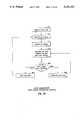
- FIG. 2is a system description flow chart for the first preferred embodiment
- FIG. 3is a flow chart describing a data acquisition method for the first preferred embodiment
- FIG. 4is a flow chart describing a parting line for the first preferred embodiment
- FIG. 5Aillustrates the ruled surface connecting the generic form and prepared tooth surface
- FIG. 5Billustrates the computer-based representation comprised of an altered generic form, a prepared tooth surface, and a ruled surface connecting the generic form and prepared tooth surface;
- FIG. 6illustrates a plurality of unwrapped radial scan lines
- FIG. 7illustrates a plurality of wrapped radial scan lines comprising the generic form
- FIG. 7illustrates a plurality of contour lines generated for the generic form
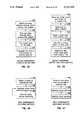
- FIG. 8is a flow chart describing a superposition method in the first preferred embodiment
- FIG. 9is a flow chart describing a scaling method in the first preferred embodiment
- FIG. 10is a flow chart describing a method for emphasizing features in the first preferred embodiment
- FIG. 11is a flow chart describing a method for shaping generic forms in the first preferred embodiment
- FIG. 12describes a dental prosthesis fitted over a prepared tooth
- FIGS. 13A and 13Billustrate the dimensions that decide the scaling factor
- FIGS. 14A and 14Billustrate an interference check between adjacent objects
- FIG. 15illustrates a digitized impression
- FIG. 16is a flow chart describing a method for contouring in the first preferred embodiment
- FIG. 17is a flow chart describing a method for generating offset tool paths in the first preferred embodiment
- FIG. 18is a flow chart describing a method of eliminating tool interferences in the first preferred embodiment
- FIG. 19is a system description flow chart for the second preferred embodiment
- FIG. 20is a flow chart describing a first data acquisition method for the second preferred embodiment
- FIG. 21is a flow chart describing a second data acquisition method for the second preferred embodiment
- FIG. 22illustrates a generic form as a series of profile lines
- FIG. 23is a flow chart describing a superimposition method in the second preferred embodiment
- FIG. 24is a flow chart describing a method for scaling coordinates in the second preferred embodiment
- FIG. 25is a flow chart describing a method of emphasizing features in the second preferred embodiment
- FIG. 26is a flow chart describing a method for generating surface patches in the second preferred embodiment
- FIG. 27is a flow chart describing a method for generating parting lines in the second preferred embodiment
- FIG. 28is a flow chart describing a method for propagating segmented searching circles in the second preferred embodiment
- FIG. 29illustrates the segmented searching circle method
- FIG. 30illustrates a surface composed of eight surface patches in a parametric domain
- FIG. 31illustrates the propagation of a searching circle on a single surface patch in the parametric domain
- FIG. 32describes a method for generating contour lines in the second preferred embodiment
- FIG. 33describes a method for generating offset tool paths in the second preferred embodiment
- FIG. 34describes a method for eliminating tool interferences in the second preferred embodiment
- FIG. 35describes a method for optimizing step lengths in both preferred embodiments
- FIG. 36illustrates the optimization of tool path step lengths in both preferred embodiments
- FIG. 37describes a method for optimizing cutter feed rates in both preferred embodiments
- FIG. 38describes a method for optimizing scallop heights in both preferred embodiments
- FIG. 39illustrates the optimization of tool path scallop heights in both preferred embodiments
- FIG. 40describes a method for fixturing workpiece materials in both preferred embodiments
- FIG. 41describes a method for machining workpiece materials in both preferred embodiments
- FIGS. 42A, 42B, 42C, and 43illustrate machining, rough cutting, and finish cutting in both preferred embodiments.
- FIG. 44illustrates a three axis machine tool used with both preferred embodiments.
- FIG. 1describes the components of the present invention. These components include a computer system 10, Computer-Aided-Design/Computer-Aided-Manufacturing (CAD/CAM) software 12, a database of generic forms 14, a machine tool 16, and a digitizer 18.
- the computer 10is a UNIX-based work station built by Silicon Graphics, Incorporated.
- the CAD/CAM software 12is a custom package that creates a computer-based model of the object, manipulates the model, and generates commands directing the machine tool 16 to reproduce the object.
- the database 14is comprised of files storing generic object forms that provide a plurality of idealized versions of the object.
- the machine tool 16is a three axis milling machine built by Servo Products Company.
- the digitizer 18is an optical, non-contact, three dimensional, surface digitizer 18 built by Laser Design Corporation. Using these components, the present invention can machine reproductions of objects of complex and precise geometry.
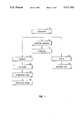
- FIG. 2describes the method steps used in a first preferred embodiment of the CAD/CAM software 12.
- the objectis radially scanned and the resulting coordinates are recorded into the computer (28).
- Radial scan linesappear to start near the center of the top of the object and proceed outward toward the bottom of the tooth. Initially, the coordinates are stored in an "unwrapped” state as successive scan lines. The radial scan lines are "clipped” to determine a parting line (30). The radial scan lines are then "wrapped" about the Z-axis to obtain a three dimensional representation of the object (32). The scanned coordinates may be superimposed onto a generic form of the object stored in the computer, thus creating an altered generic set of coordinates (34).
- Contour linesare created by connecting corresponding points on adjacent radial scan lines (36).
- the contour linesmay be projected in a normal direction to the surface to create the offset tool paths for the machine tool (38).
- Multiple offset tool pathsmay be generated to provide rough and finish cutting planes, and to achieve a desired machining tolerance.
- Tool interference checksare made to eliminate gouging (40).
- Additional machine tool commandsare generated in the computer as required (42).
- the material to be machinedis fixtured such that it may be machined sequentially by region (44).
- the offset tool paths and commandsare then transmitted from the computer to the machine tool for the machining step (46).
- FIG. 3describes a method of data acquisition in the first preferred embodiment.
- Data acquisitionis the first step in generating a computer-based representation of a three dimensional object.
- the digitizer 18is a point-by-point triangulation system.
- the digitizer 18is comprised of a three axis positioning head 20 with a low energy laser source and detector, a rotational stage 24, and a computer controller 26.
- the controller 26positions both the rotational stage 24 and the positioning head 20 (48).
- An objectis placed on the rotational stage 24, and the laser beam reflects from it. The reflected laser beam is used to measure the distance between the object and the laser source (50).
- the (Z) coordinate on the surfaceis established by combining the position of the laser source with the determined distance between the object and the laser source.
- the computer 10records the head 20 position into the database 14 as (X,Y,Z) coordinates (52). These coordinates are stored in an "unwrapped" state.
- the digitizer 18creates radial scan lines by beginning near the center of the top of the object and moving radially outward from the object.
- the controller 26orders either the rotational stage 24 or the positioning head 20 to shift to a new (X,Y) position to obtain a new (Z) value (54).
- the controller 26orders the rotational stage 24 to rotate to start a new line (56).
- the surface of the objectis scanned and represented by a grid of (X,Y,Z) position coordinates (58).
- the rotational stage 24, or just the object itselfmay be set at any angle relative to the laser source for scanning. If such an object is not angled during the scan, data may be lost.
- the digitizer 18may erroneously sense that an edge of the object has been reached and stop scanning. Data can be obtained at variable step sizes, with a minimum step size of 8 microns.
- the surfacecan be scanned at approximately ten to thirty points per second. Maximum digitizing volume is six inches by six inches by three inches.
- the CAD/CAM software 12may filter the coordinates to eliminate noise (60). Filtering eliminates any coordinates that correspond to points not substantially proximate to the radial scan line (60).
- the data acquisition method used in the first preferred embodimentis well suited to the fabrication of dental prostheses.
- Each patientpresents a unique set of teeth shapes and sizes.
- each restorationhas a unique form, depending upon the history of decay, fracture, and previous restorations.
- the data required to produce the dental prosthesisincludes: (1) the configuration of the tooth prepared by the dentist to receive the prosthesis; (2) the gap between, the heights of, and the widths of, the adjacent teeth which provides the scaling factor; (3) the surface configuration of the opposing teeth with which the prosthesis must occlude; and (4) motion of the mandible relative to the maxilla during function (in the areas where any of the teeth remain in contact and therefore guide the motion of the jaws).
- the process to create a dental prosthesisbegins in a similar fashion as the traditional wax casting techniques discussed hereinbefore.
- a dentistmakes an impression of the two arches of teeth.
- the impressionis a three-dimensional negative of the teeth shapes.
- the dentistcreates a model duplicating the teeth by pouring plaster into the impression. When the plaster has set, the impression is discarded.
- the digitizer 18scans the plaster model and records the resulting coordinates into the database 14.
- FIG. 4describes a method for generating parting lines in the first preferred embodiment.
- a parting lineis generated so that undercuts and their associated interferences are avoided during the machining step.
- the coordinatesare stored in an "unwrapped" state as successive scan lines.
- a searchis made for a point on the radial scan line with the largest Y-axis distance from the Z-axis (64).
- the first point with the largest Y-axis distancei.e., the relative maximum
- a parting lineis generated by "clipping" data on each of the radial scan lines below the selected parting line (66).
- Each of the successive radial scan linesare processed in a similar manner to form the complete parting line (68).
- a single parting line 72 in the first preferred embodimenttypically defines two major regions for a dental prosthesis 70.
- Both FIGS. 5A and 5Bare contour line representations, discussed herein later, of the dental prosthesis 70.
- One regionis a generic form 74 representing the occlusal surface and sides of the prosthesis 70 to the crests of convexity (the two maximum horizontal points in any given radial scan line to the parting line).
- the generic form 74is altered to fit the space available in the patient's mouth.
- the other regionis a prepared tooth surface 76 representing the lower part of the configuration. The prepared tooth surface 76 of the prosthesis 70 is manipulated to fit over the prepared tooth.
- a connecting surface 78 between the generic form 74 and the prepared tooth surface 76i.e., the surface below the crest of convexity, typically extending from the parting line 72 of the generic form 74 to the margin 80 of the prosthesis.
- FIG. 6is an illustration of the radial scan lines stored in an "unwrapped" state.
- FIG. 7Ais an illustration of the "wrapped" radial scan lines.
- the surface 82 of the objectis represented as a plurality of points 86 and 88 on a plurality of radial scan lines 84.
- Each radial scan line 84appears to start near the center of the top of the object and proceed outward.
- Each of the radial scan lines 84are at different angular increments around the center of the object.
- each radial scan line 84functions as a planar slice or crosssection of the three dimensional surface 82 beginning at the center of the object and extending to the outer surface.
- each generic form 82is represented in the computer 10 as a plurality of points 86 and 88 on a plurality of radial scan lines 84.
- Each radial scan line 84appears to start near the center of the top of the generic form 82 and proceed outward.
- Each of the radial scan lines 84are at different angular increments around the center of the generic form 82.
- each radial scan line 84functions as a planar slice or cross-section of the three dimensional surface beginning near the center of the generic form 82 and extending to the outer surface.
- the databasecontains a plurality of standardized generic tooth forms.
- the generic tooth forms usedare typically computer-based representations of standardized plaster models of teeth.
- FIG. 8describes a method for superimposing the scanned coordinates onto a generic form stored in the database.
- Landmarks on the generic formare matched with, and compared to, corresponding landmarks on the scanned object, thereby providing a correct orientation and size for the generic form.
- the CAD/CAM softwareretrieves a generic form from the database (90).
- the generic formis "spatially rotated” and positioned so that it corresponds to a spatial orientation of the set of coordinates scanned from the object (92). This orientation is performed by matching at least three landmarks on the generic form with corresponding landmarks on the scanned object.
- the CAD/CAM softwarealso scales the generic coordinates so they are sized substantially the same as the scanned coordinates (96). Additional coordinates may be created to prevent features from being smoothed out or eliminated (96).
- the resulting representationmay be shaped if desired (98).
- the representationmay also be checked for interferences with other objects adjacent to where the reproduction will reside (100).
- FIG. 9describes the scaling operation performed on the generic form. Gap measurements are recorded between the object and other objects adjacent to it (116). Also recorded are height and width measurements of the object and/or adjacent objects (118 and 120). The ratio of these values to the equivalent distances on the generic form yields a scaling factor. This scaling factor may be applied to the set of coordinates to create a linear transformation of the coordinates (122). Thus, the generic form can be sized to fit the space available for the reproduction. Note that with this method, a replacement part may be created using the computer-based generic form scaled according to the "gap" left for its placement, and from measurements of adjacent objects. Thus, the original object is not required when machining replacement parts, unless it is desired to construct a true, substantially identical "reproduction" of the object.
- FIG. 10describes a method for creating additional feature coordinates in the first preferred embodiment. Additional coordinates can be added to the set of coordinates to emphasize features of the object or the generic form. The additional coordinates ensure that the feature is not smoothed out, or otherwise eliminated, either by system operators or by the CAD/CAM software.
- a feature coordinateis identified within the set of coordinates (124).
- the CAD/CAM softwareplurally represents the feature coordinate by computing a plurality of parametric curves extending through the feature coordinate (126). These parametric curves are used to provide additional coordinates, thereby preventing the feature from being smoothed out or eliminated.
- FIG. 11describes a method for shaping the generic form in the first preferred embodiment.
- a point on the surface represented by a coordinateis selected and moved to a new position (128).
- the set of coordinatescan be changed, with local effects, using a free-form deformation technique (130).
- the surface geometryis deformed using a shaping function.
- the deformationsdecrease radially about the point of interest. Points very near the moved point will move almost as much. Points further away will move less, as determined by the selected shaping function, decreasing to zero movement at the selected maximum radius. This provides the equivalent of a computer shaping tool for the system operator.
- a generic tooth form 136 stored in the databasecontains a local coordinate system 140, based on maximum height (in the occlusal plane) of the cusp tips.
- the databasealso contains the positions of the proximal contacts 142 and 144 relative to that local coordinate system 140. If a landmark 146 is placed on the prepared tooth 148, a local coordinate system 150 relative to the prepared tooth 148 can be calculated. Since the two contact points 142 and 144 on the prosthesis must match the two contact points on the proximal teeth, a transformation from the generic coordinates to the prosthesis coordinates can be made. With this transformation, a scaled generic form 136 is created for the prepared tooth configuration 148.
- the design of the surfaces of the prosthesisis more complicated than simply transforming the coordinate system.
- the occlusal surface of the prosthesisis suggested by the generic tooth form stored in the database 14.
- the prosthesismust contact the adjacent teeth 152 and 154.
- the CAD/CAM softwarescales the generic tooth form so that the mesial-distal distance between proximal teeth matches the distance between contact points of the generic form.
- the scaling factor usedis simply the ratio of actual mesial-distal length over the mesial-distal length of the generic form.
- the size of the generic formcan be altered by checking the gap between the adjacent teeth 152 and 154.
- the width and height of the generic formcan be determined by measuring the thickness and height of the adjacent teeth 152 and 154. Also, the coordinates representing the fossae and cusps of the occlusal surface may be altered to raise or lower the cusps. This scaling factor is most likely provided by measuring the upper and lower teeth while in occlusion.
- FIGS. 14A and 14Bshow that the interference between the upper and lower teeth can be checked by using contour lines. Interferences are solved by moving the coordinates involved. The occlusal surface of the prosthesis 156 is checked when the maxilla tooth 158 is in contact. First, the relative positions between mandible and maxilla teeth have to be found.
- FIG. 15illustrates the data collection method. Impressions 160 in a wax plate 162 are digitized to find the relative position between the mandible and maxilla teeth. Landmarks 164 are plugged into the impression 160. The mandible and maxilla teeth can be digitized from opposite sides of the impression 160. Also, the position of the landmarks 164 are digitized. Thus, the relative position of the mandible and maxilla teeth can be calculated based on the position of the landmarks 164.
- the lower part of the prosthesis 134fits over the prepared tooth 148.
- This prepared tooth surface 134must be connected to the generic form providing the occlusal surface 136.
- a ruled surface 138e.g., straight, ruled lines
- the resulting margin of the prosthesisis usually sharp. A small error near the edge could cause severe problems, such as too loose or too tight a fit.
- FIG. 16describes a method for contouring the generic object in the first preferred embodiment.
- Each radial scan lineis reparameterized, so that all radial scan lines have the same number of coordinates (166).
- Contour linesare generated through these coordinates, matching the order of coordinates in each radial scan line (168).
- the first coordinate point in the first radial scan lineis connected to the first coordinate point in the second radial scan line
- the second coordinate point in the first radial scan lineis connected to the second coordinate point in the second radial scan line
- the contour linesare essentially perpendicular to the radial scan lines.
- These contour linesdefine the machine tool 16 contact point on the surface of the prosthesis.
- Enough contour linesare generated to connect all coordinates (170).
- the contour linesmay be selectively altered to provide offset tool paths from the reproduction surface (172 and 174). Offset tool paths are generated in such a way as to prevent the machine tool 16 from erroneously intersecting with the surface of the prosthesis. Offsets can be applied to regions automatically selected by the CAD/CAM software. Alternatively, offsets can be applied to regions manually selected by a systems operator.
- FIG. 17describes a method for generating offset tool paths in the first preferred embodiment.
- the CAD/CAM softwareselects an offset angle and an offset height from the contour line (176). The offset angle and offset height can be selected arbitrarily. The offset angle and the offset height determine the offset distance (178). A data point is projected the offset distance from the contour line (180).
- the CAD/CAM softwarecalculates the normal vectors to the contour lines at each coordinate point (182). The CAD/CAM software determines a new offset data point by shifting the data point offset distance along the normal vector from the contour line (184).
- FIG. 18describes a method for preventing tool interferences in the first preferred embodiment.
- the CAD/CAM softwareperforms a computation to prevent the offset tool paths from erroneously intersecting with the prosthesis surface represented by the original scan lines or the original contour lines.
- the CAD/CAM softwarechecks the minimum radii of principal curvature at the vertices or coordinate points of the offset tool paths (186).
- the vertices where the minimum radius is smaller than the machine tool 6 radiusare identified (188).
- the CAD/CAM softwarefinds a curve of intersection of each identified vertex with a plane.
- the planepasses through the identified vertex and contains a first vector normal to the surface and a second vector in the direction of the minimum radius (190).
- a plurality of line segments of the intersection curveare generated, which line segments intersect together (192).
- the line segmentsare subdivided using a segmentized searching circle, described hereinbelow, until an error value between the line segments and the surface approaches a predetermined tolerance value (194).
- a segmentized searching circleis computed for the two adjacent surface areas (196). An intersection between a plurality of triangular segments of the segmentized searching circles is found (198). The triangular segments are bisected (200). An intersection between the triangular segments is formed (202). These steps are repeated (i.e., the segmentized searching circle computing step (196) through the intersection finding step (202)) until an error value between a plurality of intersected edges of the triangular segments and the surface approaches the predetermined tolerance (204).
- the segmentized searching circlesare propagated until the circles meet or until the circles reach one of a plurality of boundaries for the surface areas (206). These steps are repeated (i.e., the curve of intersection finding step (190) through the segmentized searching circle propagating step (206)) until all identified vertices are processed (208).
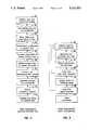
- FIG. 19describes the method steps used in a second preferred embodiment of the CAD/CAM software.
- the objectis scanned and coordinates describing the object are recorded into the computer (210). More than one set of coordinates may be recorded for each object.
- the set of coordinatesmay be superimposed onto a generic form of the object stored on the computer (212).
- the generic formis comprised of a generic set of coordinates. The superposition of the recorded coordinates thus creates an altered generic set of coordinates. If the object is represented by more than one set of coordinates, the sets are connected to create a master set of coordinates (214). A plurality of surface patches are computed from the master set of coordinates (216).
- Parting linesmay be generated to divide the surface patches into a plurality of regions, thus preventing undercuts by the machine tool 16 (218).
- Contour linesare generated from the surface patches (220).
- Offset tool pathsare generated from the contour lines that provide a predetermined offset from the surface patches for the machine tool 16 (222).
- a computationis performed on the offset tool paths to prevent the machine tool 16 from erroneously intersecting with the surface patches (224).
- Additional machine tool commandsare generated in the computer 10 (226).
- the workpiece materialis fixtured such that it may be machined sequentially by region (228).
- the offset tool paths and commandsare transmitted from the computer 10 to the machine tool 16 (230).
- FIGS. 20 and 21describe two alternative methods of data acquisition in the second preferred embodiment.
- the digitizeris the same used in the first preferred embodiment.
- profile linesrather than radial scan lines are recorded for each object.
- Profile linesappear to be planar slices of the three dimensional surface of the scanned object.
- the digitizerprojects a plurality of points onto the object (232).
- the second preferred embodimentscans the three dimensional object (234) and records the resulting set of coordinates of points into the computer (236). More than one set of scanned coordinates can be created to represent each object.
- the CAD/CAM softwareconverts the set of coordinates into a plurality of profile lines (238) and filters the set of coordinates to eliminate noise (240). Filtering eliminates any coordinates that correspond to points no substantially proximate to the profile lines.
- the scanned coordinates representing the profile linesare modified to ensure that each of the profile lines has substantially the same number of coordinates as adjacent profile lines (242).
- the digitizerprojects a plurality of profile lines onto the object (244).
- the three dimensional objectis scanned (246) and the resulting set of coordinates is recorded into the computer (248). More than one set of coordinates can be created to represent each object.
- the CAD/CAM softwarefilters the set of coordinates to eliminate noise (250). Filtering eliminates any coordinates that correspond to points not substantially proximate to the profile lines.
- the scanned coordinates representing the profile linesare modified to ensure that each of the profile lines has substantially the same number of coordinates as adjacent profile lines (252).
- the data acquisition method used in the second preferred embodimentlike that of the first preferred embodiment, is well suited to the fabrication of dental prostheses. Each patient presents a unique set of teeth shapes and sizes.
- each restorationhas a unique form, depending upon the history of decay, fracture, and previous restorations.
- the data required to produce the dental prosthesisincludes: (1) the configuration of the tooth prepared by the dentist to receive the prosthesis; (2) the gap between, the heights of, and the widths of, the adjacent teeth which provides the scaling factor; (3) the surface configuration of the opposing teeth with which the prosthesis must occlude; and (4) motion of the mandible relative to the maxilla during function (in the areas where any of the teeth remain in contact and therefore guide the motion of the jaws).
- the process to create a dental prosthesisbegins in a similar fashion as the traditional wax casting techniques discussed hereinbefore. A dentist makes an impression of the two arches of teeth.
- the impressionis a three-dimensional negative of the teeth shapes.
- the dentistcreates a model duplicating the teeth by pouring plaster into the impression. When the plaster has set, the impression is discarded.
- the digitizerscans the plaster model and records the resulting coordinates into the database.
- FIG. 22is an illustration of the profile lines.
- the profile linesrepresent the surface of the object as a plurality of points 254 on a plurality of profile lines 256.
- Each of the profile lines 256are at different increments along the surface of the object.
- each profile line 256functions as a planar slice of the three dimensional surface of the scanned object.
- the databasecontains a plurality of standardized object representations, referred to as generic forms.
- the generic formis comprised of a generic set of (X,Y,Z) coordinates.
- the generic formpermits the fabrication of reproductions based on idealized or standardized geometries.
- the surface of each generic formis represented in the computer as a plurality of points 254 on a plurality of profile lines 256.
- Each of the profile lines 256are at different increments along the surface of the generic form.
- each profile line 256functions as a planar slice of the three dimensional surface of the generic form.
- the databasecontains a plurality of standardized generic tooth forms.
- the generic tooth forms usedare typically computer-based representations of standardized plaster models of teeth.
- FIG. 23describes a method for superimposing the scanned coordinates onto a generic form stored in the database.
- Landmarks on the generic formare matched with, and compared to, corresponding landmarks on the scanned object, thereby providing a correct orientation and size for the generic form.
- the CAD/CAM softwareretrieves a generic form from the database (258).
- the generic formis "spatially rotated" and positioned so that it corresponds to a spatial orientation of the set of coordinates scanned from the object (260). This orientation is performed by matching at least three landmarks on the generic form with corresponding landmarks on the scanned object.
- the CAD/CAM softwarealso scales the generic coordinates so they are sized substantially the same as the scanned coordinates (262). Additional coordinates are created to emphasize features of the object or generic form (264). Interferences among objects are eliminated (266).
- FIG. 24describes the scaling operation performed on the generic form. Gap measurements are recorded between the object and other objects adjacent to it (268). Also recorded are height and width measurements of the object and/or adjacent objects (270,272). The ratio of these values to the equivalent distances on the generic form yields a scaling factor. This scaling factor may be applied to the set of coordinates (274). Thus, the generic form can be sized to fit the space available for the reproduction. Note that with this method, a replacement part may be created using the computer-based generic form scaled according to the "gap" left for its placement, and from measurements of adjacent objects. Thus, the original object is not required when machining replacement parts, unless it is desired to construct a true, substantially identical "reproduction" of the object.
- FIG. 25describes a method for creating additional feature coordinates in the second preferred embodiment. Additional coordinates can be added to the set of coordinates to emphasize features of the object or the generic form. The additional coordinates ensure that the feature is not smoothed out, or otherwise eliminated, either by system operators or by the CAD/CAM software.
- a feature coordinateis identified within the set of coordinates (276).
- the CAD/CAM softwareplurally represents the feature coordinate by computing a plurality of parametric curves extending through the feature coordinate (278). These parametric curves are used to provide additional coordinates, thereby preventing the feature from being smoothed out or eliminated.
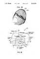
- FIG. 12illustrates this incorporation.
- a generic tooth form 136 stored in the databasecontains a local coordinate system 140, based on maximum height (in the occlusal plane) of the cusp tips.
- the databasealso contains the positions of the proximal contacts 142 and 144 relative to that local coordinate system 140. If a landmark 146 is placed on the prepared tooth 148, a local coordinate system 150 relative to the prepared tooth 148 can be calculated. Since the two contact points 142 and 144 on the prosthesis must match the two contact points on the proximal teeth, a transformation from the generic coordinates to the prosthesis coordinates can be made. With this transformation, a scaled generic form 136 is created for the prepared tooth configuration 148.
- the design of the surfaces of the prosthesisis more complicated than simply transforming the coordinate system.
- the occlusal surface of the prosthesisis suggested by the generic tooth form stored in the database.
- the prosthesismust contact the adjacent teeth 152 and 154.
- the CAD/CAM softwarescales the generic tooth form so that the mesial-distal distance between proximal teeth matches the distance between contact points of the generic form.
- the scaling factor usedis simply the ratio of actual mesial-distal length over the mesial-distal length of the generic form.
- the size of the generic formcan be altered by checking the gap between the adjacent teeth 152 and 154.
- the width and height of the generic formcan be determined by measuring the thickness and height of the adjacent teeth 152 and 154. Also, the coordinates representing the fossae and cusps of the occlusal surface may be altered to raise or lower the cusps. This scaling factor is most likely provided by measuring the upper and lower teeth while in occlusion.
- FIGS. 14A and 14Bshow that the interference between the upper and lower teeth can be checked by using contour lines. Interferences are solved by moving the coordinates involved.
- the occlusal surface of the prosthesis 156is checked when the teeth of the mandible and maxilla are in contact.
- FIG. 15illustrates the data collection method. Impressions 160 in a wax plate 162 are digitized to find the relative position between the mandible and maxilla teeth.
- Landmarks 164are plugged into the impression 160.
- the mandible and maxilla teethcan be digitized from opposite sides of the impression 160.
- the positions of the landmarks 164are digitized.
- the relative position of the mandible and maxilla teethcan be calculated based on the position of the landmarks 164.
- the lower part of the prosthesis 134fits over the prepared tooth.
- This prepared tooth surface 134must be connected to the generic form providing the occlusal surface 136.
- a ruled surface 138e.g., straight, ruled lines
- the resulting margin of the prosthesisis usually sharp. A small error near the edge could cause severe problems, such as too loose or too tight a fit.
- FIG. 26describes a method for computing surface patches from the scanned coordinates in the second preferred embodiment.
- a plurality of parametric curvesare derived from the coordinates (280).
- the surface patchesare created from the parametric curves (282).
- the combined surface patchesprovide a three dimensional representation of the object (284).
- the surface patchesare defined by bi-cubic uniform B-splines with multiple knots for boundaries.
- B-splinesare used for a number of reasons: (1) the surface can be changed locally by simply moving control vertices; (2) the control vertices approximate the interpolated surface; and (3) the surface can be constructed with simple equations.
- the B-spline geometryensures continuity across the surface of the object without sudden changes to second order derivatives. This property ensures aesthetics and simplifies subsequent machining.
- the prostheses surfacesare smooth and continuous. All external surfaces can be polished with round burrs because they are blended surfaces. Thus, there are no sharp points on the surface. These aesthetics are preserved with the use of B-splines.
- machining beginsit is important to avoid sudden accelerations. Otherwise, damaged or broken tools result, and the workpiece materials may be gouged or torn. By ensuring continuity across the surface patches to second order derivatives, these problems can be eliminated.
- FIG. 27describes a method for generating parting lines in the second preferred embodiment.
- Parting line generationoccurs in the second preferred embodiment after the surface patches have been constructed. This allows the surface patches to be divided into regions by a parting line, so that undercuts and their associated interferences are avoided.
- the parting line on a surface patchis perpendicular to the cross-product of two vectors.
- the first vectoris parallel to a first axis of the machine tool (the vertical Z-axis of a 3-axis milling machine).
- the second vectoris a normal vector of a point on a surface patch.
- the CAD/CAM softwarefinds those surface patches through which the parting line passes (286). An edge of these surface patches has end points with different signs of surface normal component values parallel to an axis of the machine tool. A seed point is found on the edge (boundary) of a marked surface patch at which the component of the surface normal vector parallel to the machine tool axis equals zero (288). The seed point on the edge of the surface patch can be found, for example, by successively bisecting the edge until the surface normal component is zero.
- the parting lineis propagated using a segmentized searching circle until an edge of an adjacent surface patch is encountered (290). An edge point of the adjacent surface patch is identified (292) and the seed point is replaced (294). These steps are repeated (i.e., the propagating step (290) through the replacing step (294)) until all found surface patches are processed (296).
- a single parting line in the second preferred embodimenttypically defines two major regions for a dental prosthesis.
- One part of the configurationis a generic form 136 representing the occlusal surface and sides of the prosthesis to the crests of convexity (the two maximum horizontal points in any given radial scan line to the parting line).
- the generic form 136is altered to fit the space available in the patient's mouth.
- the prepared tooth surface 148determines the other part of the configuration.
- the lower part of the prosthesis 134is manipulated to fit over the prepared tooth 148.
- Also included in this regionis a connecting surface 138 between the generic form and the prepared tooth surface, i.e., the surface below the crest of convexity, typically extending from the parting line to the margin of the prosthesis.
- FIG. 28describes a searching circle method of propagating lines through surface patches.
- the segmentized searching circleis propagated by first generating a plurality of enclosing points to create a substantially polygonal representation about a seed point (298).
- a plurality of line segmentsare derived between the enclosing points to enclose the seed point.
- the pointsare checked (300) to find two adjacent points which have different signs of surface normal components parallel to the machine tool axis (302).
- a new plurality of points with finer spacingare generated between the two points and the process repeats until the desired accuracy is obtained (304). These steps are repeated (i.e., the checking step (300) through the generating step (304)) until an edge of an adjacent surface patch is encountered (306).
- FIG. 29illustrates the segmented searching circle algorithm.
- a segmentized searching circleis a modification of the bisection algorithm. If any continuum is being searched for points having a particular value and a seed point 308 is known which has that value, an adjacent point having that value can be located by drawing a circle 310 about the seed point 308 and evaluating points 312, 314, 316, and 318 on the circumference of that circle 310. Instead of evaluating all points on the circumference, only the selected points 312, 314, 316, and 318 are evaluated to locate a segment that contains the desired value. The segment is successively subdivided until a point equal to or sufficiently close to the desired value is located. Subdivision is accomplished by mathematically rotating the search vector.
- the seed point 308when this method is applied to searching, the seed point 308 must be found first.
- four points 312, 314, 316, and 318, on the circle 310are evaluated and each segment between two points is checked for the given value. If a segment is found, it will be subdivided until the given tolerance or cut-off criterion is reached.
- the searching radiuscan be changed if necessary. Note that for successive steps, the point found at the given radius becomes the new seed point and the old seed point 308 is used as the first point on the search circle.
- FIG. 30shows a surface 320 as defined by 4 ⁇ 2 normalized parametric patches A-H.
- a surface S(x,y,z), in cartesian coordinates,is the mapping of a surface P(u,w), in the parametric domain, wherein P(u,w) is the equation of a uniform bi-cubic B-spline surface.
- Each patch A-Hhas 4 ⁇ 4 subpatches.
- a curve 322passes through normalized parametric patches B, F and G.
- FIG. 31is a magnification of region B. Initially, a seed point 324 must be found, using any convenient method such as a bisection algorithm. If a seed point 324 is found between subpatch 2 and 3, there are two intersection points between the curve 322 and the searching circle 326.
- subpatch 3is selected for processing, the edge between 2 and 3 is marked. Subpatch 3 is selected by examining normal vectors. The center of the searching circle 326 is updated by moving it to the point most recently located on the curve 322. If the searching circle 326 meets the boundary of the normalized parametric patch B, subpatch 3 is marked as processed and the center of the searching circle 326 moves to the point in subpatch 2 which was found earlier. Then, subpatch 2 is processed. When the searching circle 326 passes the edge between subpatch 2 and 6, subpatch 2 is marked as processed. If the searching circle 326 meets the boundary of normalized parametric patch B, the seed point on the boundary of normalized parametric patch F is computed from calculations based on the normal vector. This sequence continues until all patches are processed.
- FIG. 32describes a method for contouring surface patches in the second preferred embodiment. Contouring involves finding an intersection curve between a surface patch and a contour plane. The surface patches are contoured to provide a plurality of offset tool paths for the machine tool.
- the CAD/CAM softwarefirst identifies all surface patches through which a contour line passes (328). An edge of the identified surface patch is found (330). A seed point is selected on the edge (332). The seed point may be found, for example, by bisecting the edge.
- the contour lineis propagated from the seed point using a segmentized searching circle until it processes all of the identified surface patches (334).
- FIG. 33describes a method for creating offset tool paths in the second preferred embodiment.
- Offsetscan be applied to regions automatically selected by the CAD/CAM software. Alternatively, offsets can be applied to regions manually selected by an operator.
- the CAD/CAM softwareselects an offset angle and an offset height from the contour line (336). The offset angle and the offset height determine the offset distance (338).
- a data pointis projected from the contour line onto a plane to simplify normal vector calculation (340).
- a normal vectoris calculated at this data point (342).
- a new offset data pointis determined by shifting the data point offset a distance along the normal vector (344).
- FIG. 34describes a method for preventing tool interference in the second preferred embodiment.
- the methodprevents the machine tool from erroneously intersecting with one of the surface patches.
- the CAD/CAM softwarechecks the minimum radii of principal curvature at a plurality of vertices of the surface patches (346). The vertices where the minimum radius is smaller than the tool radius are identified (348).
- the CAD/CAM softwarefinds a curve of intersection of each identified vertex with a plane. The plane passes through the identified vertex and contains a first vector normal to the offset patch and a second vector in the direction of the minimum radius (350). A plurality of line segments of the intersection curve are generated, which line segments intersect together (352).
- the line segmentsare subdivided using a segmentized searching circle, until an error value between the line segments and the surface patch approaches a predetermined tolerance value (354).
- a segmentized searchingis computed circle for the two adjacent surface patches (356).
- An intersection between a plurality of triangular segments of the segmentized searching circlesis found (358).
- the triangular segmentsare bisected (360).
- An intersection between the triangular segmentsis formed (362).
- the segmentized searching circlesare propagated until the circles meet or until the circles reach one of a plurality of boundaries for the surface patches (366). These steps are repeated (i.e., the curve of intersection finding step (350) through the segmentized searching circle propagating step (366)) until all identified vertices are processed (368).
- FIG. 35describes a method for optimizing offset tool paths in both preferred embodiments.
- FIG. 36illustrates offset tool paths 386 and 387.
- the CAD/CAM softwarecan optimize the step length of the cutter 396 along the tool paths 386 and 387 (370). Since the desired surface 384 is known (372), along with a possible tool path 387 of length 388 (374), the maximum error 390 can be obtained (376). If the maximum error 390 is larger than an allowable value (380), the tool path length 388 is subdivided (382) until the calculated error 394 is less than an allowable value (384). The reduction in tool path step length 392 is determined by the known surface 384 and the allowable value for the calculated error 394.
- FIG. 37describes a method for optimizing the cutter feed rate in both preferred embodiments. Based on the characteristics of the machine tool (398), the cutter (400), a spindle speed (402), a feed rate (404), a depth of cut (406), and the type of material machined (408), the depth of cut is calculated from known surface geometries (410). An expected cutting force is calculated for the feed rate in the immediately preceding tool path increment (412). This expected force is compared with a limiting value of force based on cutter size and material (414). Feed rate in the current tool movement increment is adjusted to produce an estimated cutting force of a predefined fraction of the limiting force value (416).
- FIG. 38describes a method for optimizing scallop heights in both preferred embodiment.
- FIG. 39graphically illustrates the optimization of the scallop height.
- the machining parametersinclude the characteristics of the tool path (418), the distance between tool paths (420), the spindle speed (422), the feed rate (424), the characteristics of the material (426), and the size of the cutter 446 (428).
- the scallop height 436is compared with a predetermined maximum value (430), and if the scallop height 436 exceeds the predetermined maximum value (432), the distance between adjacent tool paths 438 is reduced and the offset tool paths are adjusted (434).
- the distance 438is specific to the cutter geometry and machined surface profile, particularly the cutter radius 440 and surface curvature 442.
- FIG. 40describes a method for fixturing in both preferred embodiments.
- a blank of the workpiece materialis chosen (448).
- the blankis oriented according to the spatial orientation of the set of coordinates (450).
- the workpiece materialis held on a bed surface of the machine tool to prevent movement while the machine tool operates (452).
- the blankalso may be selected from plurality of rough cut, preformed blanks. These preformed blanks, which correspond to generic forms stored in the database, eliminate the need for multiple machining passes for each region.
- the correct blanks preformed blanksare selected by the CAD/CAM software.
- a modified visemay be attached to the bed of the machine tool to hold the blank.
- a special fixtureis milled, representing the configuration of where the reproduction is to fit. When used to produce dental prostheses, this configuration represents the prepared tooth (similar to a die in the wax casting technique).
- the internal surface and tee external surface of the reproductionare milled to the heights of contour from another blank.
- the partially fabricated reproductionis removed from the vise and placed onto the fixture. When used to produce dental prostheses, this preserves the relative orientation between the internal and external surfaces when the final occlusal surface is machined.
- the partially fabricated reproductionis held in place with either sticky wax or epoxy.
- the fixtureis held with the vise while the remaining portion of the external surface is cut.
- the fixturecan also serve as a holding device and can be used during shipping as protection for the margins. This protection is probably not critical for metal reproductions, but may very practical for ceramic reproductions which are brittle and more susceptible to fracture and cracking.
- one or more parting linescan divide the three dimensional representation of the object into top and bottom portions.
- the bottom portionis machined first.
- the objectis then flipped and the bottom portion is secured onto the fixture.
- the top portionis machined, completing the reproduction.
- FIG. 41describes a method of machining used in both preferred embodiments.
- the machining operationbegins with the transmittal of the tool paths and commands from the CAD/CAM software to the machine tool (454).
- the machine toolmachines both rough and finish surfaces as transmitted (456,458).
- the tool pathsare transmitted by region, so that the machine tool, may if desired, machine a blank by region according to the tool paths received.
- FIGS. 42A, 42B, 42C, and 43illustrate the machining process.
- the surface of the raw stock or blank 460 and the offset 464 of the part surface 466are the geometrical constraints that determine the tool paths for the rough (if required) and finish cutting.
- the offset value 464is determined by the tool radius plus the material left for finish cutting.
- Rough cuttingis the process of removing the bulk of the material 462 from the raw stock 460, using the full capability of the machine tool.
- the factors related to roughingare the available spindle power, tools, and material properties.
- the tool path for roughingdepends on the shape of the raw stock 460 and the offset surface 464.
- the cutting plane 468moves down according to the maximum cutting depth along the Z axis. For each cutting plane 468, the intersection lines between the raw stock 460 and the offset surface 464 have to be calculated to determine the roughing area 462.
- the roughing area 462can be removed by contour cutting. Starting at a tool path that produces the desired contour, the machining continues outward until all rough cutting material is removed. If the machine tool meets the offset surface 464, it is retracted, moved to a position above the next rough cutting tool path and lowered to the cutting plane 468 to continue the rough cutting. The process repeats until all the rough cutting area 462 is removed.
- Finish cuttingremoves the small amount of excess material left during the roughing process, thus bringing the surface of the reproduced object 472 to the required geometry and surface finish.
- the feed rateis low and spindle speed high.
- the tool path for the finish cuttingis determined by finding the intersection lines between the offset surface and the X-Z plane in FIG. 42A.
- Polishingis the final process of eliminating all machining marks and shining the surface. This process can be done by using a rotating brush, grinding tool, or it can be performed manually.
- FIG. 44illustrates both one possible fixturing method and a three axis machine tool.
- a blank workpiece of appropriate sizeis chosen and placed in the adaptable fixture 478.
- the holder 478secures the workpiece in place.
- a region of the workpieceis machined using the cutting tool 474.
- the workpieceis removed from the fixture 478 and re-oriented.
- the workpiecemay also be secured in different size fixtures 480-490.
Landscapes
- Health & Medical Sciences (AREA)
- Engineering & Computer Science (AREA)
- Physics & Mathematics (AREA)
- Animal Behavior & Ethology (AREA)
- Manufacturing & Machinery (AREA)
- Epidemiology (AREA)
- General Health & Medical Sciences (AREA)
- Public Health (AREA)
- Veterinary Medicine (AREA)
- Dentistry (AREA)
- Oral & Maxillofacial Surgery (AREA)
- Life Sciences & Earth Sciences (AREA)
- General Physics & Mathematics (AREA)
- Software Systems (AREA)
- Geometry (AREA)
- Theoretical Computer Science (AREA)
- Computer Graphics (AREA)
- Human Computer Interaction (AREA)
- Automation & Control Theory (AREA)
- Dental Tools And Instruments Or Auxiliary Dental Instruments (AREA)
Abstract
Description
Claims (39)
Priority Applications (2)
| Application Number | Priority Date | Filing Date | Title |
|---|---|---|---|
| US07/365,139US5121333A (en) | 1989-06-09 | 1989-06-09 | Method and apparatus for manipulating computer-based representations of objects of complex and unique geometry |
| US07/869,764US5257203A (en) | 1989-06-09 | 1992-04-16 | Method and apparatus for manipulating computer-based representations of objects of complex and unique geometry |
Applications Claiming Priority (1)
| Application Number | Priority Date | Filing Date | Title |
|---|---|---|---|
| US07/365,139US5121333A (en) | 1989-06-09 | 1989-06-09 | Method and apparatus for manipulating computer-based representations of objects of complex and unique geometry |
Related Child Applications (1)
| Application Number | Title | Priority Date | Filing Date |
|---|---|---|---|
| US07/869,764DivisionUS5257203A (en) | 1989-06-09 | 1992-04-16 | Method and apparatus for manipulating computer-based representations of objects of complex and unique geometry |
Publications (1)
| Publication Number | Publication Date |
|---|---|
| US5121333Atrue US5121333A (en) | 1992-06-09 |
Family
ID=23437629
Family Applications (1)
| Application Number | Title | Priority Date | Filing Date |
|---|---|---|---|
| US07/365,139Expired - LifetimeUS5121333A (en) | 1989-06-09 | 1989-06-09 | Method and apparatus for manipulating computer-based representations of objects of complex and unique geometry |
Country Status (1)
| Country | Link |
|---|---|
| US (1) | US5121333A (en) |
Cited By (289)
| Publication number | Priority date | Publication date | Assignee | Title |
|---|---|---|---|---|
| WO1993009507A1 (en)* | 1991-11-08 | 1993-05-13 | Aura Systems, Inc. | Machine tool fixture computer aided setup |
| US5247487A (en)* | 1991-06-17 | 1993-09-21 | Spatial Positioning Systems, Inc. | Spatial measurement recovery system |
| US5257184A (en)* | 1990-04-10 | 1993-10-26 | Mushabac David R | Method and apparatus with multiple data input stylii for collecting curvilinear contour data |
| WO1995015131A1 (en)* | 1993-12-04 | 1995-06-08 | Harald Eufinger | Process for producing endoprostheses |
| US5442572A (en)* | 1992-11-23 | 1995-08-15 | Ford Motor Company | Method and system for comparing free-form geometries using high density point data models |
| US5475613A (en)* | 1991-04-19 | 1995-12-12 | Kawasaki Jukogyo Kabushiki Kaisha | Ultrasonic defect testing method and apparatus |
| WO1995029053A3 (en)* | 1994-04-25 | 1996-01-18 | 3D Systems Inc | Enhanced building techniques in stereolithography |
| US5487012A (en)* | 1990-12-21 | 1996-01-23 | Topholm & Westermann Aps | Method of preparing an otoplasty or adaptive earpiece individually matched to the shape of an auditory canal |
| US5557719A (en)* | 1991-10-30 | 1996-09-17 | Sony Corp. | Method and apparatus for forming objects based on free-form curves and free-form surfaces from projecting nodal points and a series of points onto a patch |
| US5638301A (en)* | 1994-06-02 | 1997-06-10 | Ford Motor Company | Method and system for inspecting die sets using free-form inspection techniques |
| FR2744012A1 (en)* | 1996-01-31 | 1997-08-01 | Choplin Dominique | METHOD FOR MANUFACTURING DENTAL PROSTHESES |
| US5659493A (en)* | 1995-03-03 | 1997-08-19 | Ford Motor Company | Virtual machining techniques for modifying computer models of parts |
| GB2318058A (en)* | 1996-09-25 | 1998-04-15 | Ninian Spenceley Peckitt | Three-dimensional modelling of maxillofacial implants |
| EP0854406A1 (en)* | 1997-01-21 | 1998-07-22 | Ford Global Technologies, Inc. | Method of predicting volume of finished combustion chambers from a raw cylinder head casting |
| EP0875751A1 (en) | 1997-05-02 | 1998-11-04 | General Electric Company | Computed tomography metrology |
| US5965079A (en)* | 1995-04-25 | 1999-10-12 | 3D Systems, Inc. | Method and apparatus for making a three-dimensional object by stereolithography |
| WO2000019285A1 (en)* | 1998-09-25 | 2000-04-06 | Fidia S.P.A. | Process and system for working a workpiece through numerically controlled machine tools |
| US6084586A (en)* | 1991-10-29 | 2000-07-04 | Sony Corporation | Method and apparatus for forming objects based on free-form curves and free-form surfaces generated by minimizing sum of distances from an input series of points to a free-form curve |
| US6152731A (en)* | 1997-09-22 | 2000-11-28 | 3M Innovative Properties Company | Methods for use in dental articulation |
| US6200135B1 (en)* | 1997-01-28 | 2001-03-13 | Iris Development Corporation | Scanning apparatus fixture for holding impression trays |
| US20010056436A1 (en)* | 2000-06-26 | 2001-12-27 | Autodesk, Inc. | Providing access to application data items of an application program |
| US20020055800A1 (en)* | 2000-02-17 | 2002-05-09 | Sergey Nikolskiy | Efficient data representation of teeth model |
| US20020102009A1 (en)* | 1998-06-19 | 2002-08-01 | Align Technology, Inc. | Manipulating a digital dentition model to form models of individual dentition components |
| US20020138237A1 (en)* | 2001-03-26 | 2002-09-26 | Jan Topholm | CAD/CAM system for designing a hearing aid |
| US20020187451A1 (en)* | 2000-04-25 | 2002-12-12 | Align Technology, Inc. | Systems and methods for varying elastic modulus appliances |
| US20020192617A1 (en)* | 2000-04-25 | 2002-12-19 | Align Technology, Inc. | Embedded features and methods of a dental appliance |
| US6533062B1 (en)* | 2000-09-25 | 2003-03-18 | Phonak Ag | Production process for custom-moulded ear-plug devices |
| US6540045B1 (en)* | 2000-06-30 | 2003-04-01 | Phonak Ag | Method for manufacturing an ear device and ear device |
| US20030074174A1 (en)* | 2000-10-06 | 2003-04-17 | Ping Fu | Manufacturing methods and systems for rapid production of hearing-aid shells |
| US6568936B2 (en) | 2000-01-05 | 2003-05-27 | Pentron Laboratory Technologies, Llc. | Method and apparatus for preparing dental restorations |
| US20030139834A1 (en)* | 2000-02-17 | 2003-07-24 | Align Technology, Inc. | Efficient data representation of teeth model |
| US20030190576A1 (en)* | 2000-04-25 | 2003-10-09 | Align Technology, Inc. A Delaware Corporation | Embedded features and methods of a dental appliance |
| US20030198917A1 (en)* | 2000-04-25 | 2003-10-23 | Align Technology, Inc. | Methods and systems for modeling bite registration |
| US20030203334A1 (en)* | 1998-12-04 | 2003-10-30 | Align Technology, Inc. | Manipulable dental model system for fabrication of a dental appliance |
| US20030207227A1 (en)* | 2002-05-02 | 2003-11-06 | Align Technology, Inc. | Systems and methods for treating patients |
| US6646641B1 (en) | 1999-12-08 | 2003-11-11 | Autodesk, Inc. | Extrapolation of behavioral constraints in a computer-implemented graphics system |
| US20030211440A1 (en)* | 2000-09-21 | 2003-11-13 | Align Technology, Inc. | Methods and systems for concurrent tooth repositioning and substance delivery |
| US20030214501A1 (en)* | 2002-04-29 | 2003-11-20 | Hultgren Bruce Willard | Method and apparatus for electronically generating a color dental occlusion map within electronic model images |
| US20030219691A1 (en)* | 1999-01-15 | 2003-11-27 | Align Technology, Inc | System and method for producing tooth movement |
| US20030235803A1 (en)* | 2002-06-21 | 2003-12-25 | Align Technology, Inc. | Systems and methods for automated bite-setting of tooth models |
| US20040023188A1 (en)* | 2000-08-16 | 2004-02-05 | Align Technology, Inc. | Systems and methods for removing gingiva from computer tooth models |
| US20040023183A1 (en)* | 1999-05-13 | 2004-02-05 | Align Technology, Inc. | System and methods for dental treatment planning |
| US20040038168A1 (en)* | 2002-08-22 | 2004-02-26 | Align Technology, Inc. | Systems and methods for treatment analysis by teeth matching |
| US20040048223A1 (en)* | 1997-06-20 | 2004-03-11 | Align Technology, Inc. | Attachment devices and methods for a dental appliance |
| US20040096799A1 (en)* | 2000-03-30 | 2004-05-20 | Align Technology, Inc. | System and method for separating three-dimensional models |
| US20040107080A1 (en)* | 2001-03-02 | 2004-06-03 | Nikolaj Deichmann | Method for modelling customised earpieces |
| US20040110110A1 (en)* | 1997-06-20 | 2004-06-10 | Align Technology, Inc. | Computer automated development of an orthodontic treatment plan and appliance |
| US20040118315A1 (en)* | 2001-03-13 | 2004-06-24 | Dieter Reichel | Guideway girder |
| US20040128010A1 (en)* | 2000-02-17 | 2004-07-01 | Align Technology, Inc. | Efficient data representation of teeth model |
| US20040142299A1 (en)* | 2000-04-25 | 2004-07-22 | Align Technology, Inc. | Methods for correcting deviations in preplanned tooth rearrangements |
| US20040152036A1 (en)* | 2002-09-10 | 2004-08-05 | Amir Abolfathi | Architecture for treating teeth |
| US20040170943A1 (en)* | 1998-10-08 | 2004-09-02 | Align Technology, Inc. | System and method for positioning teeth |
| US20040175671A1 (en)* | 1997-06-20 | 2004-09-09 | Align Technology, Inc. | Subdividing a digital dentition model |
| US20040191728A1 (en)* | 2000-09-08 | 2004-09-30 | Align Technology, Inc. | Modified tooth positioning appliances and methods and systems for their manufacture |
| US20040191719A1 (en)* | 2002-01-10 | 2004-09-30 | Align Technology, Inc. | System and method for positioning teeth |
| US20040197728A1 (en)* | 2002-09-10 | 2004-10-07 | Amir Abolfathi | Architecture for treating teeth |
| US20040209218A1 (en)* | 1998-11-30 | 2004-10-21 | Align Technology, Inc. | System and method for releasing tooth positioning appliances |
| US20040229183A1 (en)* | 2001-10-29 | 2004-11-18 | Peter Knopp | Polar attachment devices and method for a dental appliance |
| US20040229185A1 (en)* | 2003-02-26 | 2004-11-18 | Align Technology, Inc. | Systems and methods for fabricating a dental template with a 3-D object placement |
| US20040243361A1 (en)* | 2002-08-19 | 2004-12-02 | Align Technology, Inc. | Systems and methods for providing mass customization |
| US20040253562A1 (en)* | 2003-02-26 | 2004-12-16 | Align Technology, Inc. | Systems and methods for fabricating a dental template |
| US6835066B2 (en)* | 2001-01-31 | 2004-12-28 | Gc Corporation | Process for preparing dental prosthesis |
| US20050003319A1 (en)* | 2003-07-01 | 2005-01-06 | Align Technology, Inc. | Dental appliance sequence ordering system and method |
| US20050019721A1 (en)* | 2000-12-13 | 2005-01-27 | Align Technology, Inc. | Systems and methods for positioning teeth |
| US20050026102A1 (en)* | 2000-12-29 | 2005-02-03 | Align Technology, Inc. | Methods and systems for treating teeth |
| US20050042569A1 (en)* | 2003-02-26 | 2005-02-24 | Phan Loc X. | Systems and methods for fabricating a dental template |
| US20050048432A1 (en)* | 2002-08-22 | 2005-03-03 | Align Technology, Inc. | Systems and methods for treatment analysis by teeth matching |
| US20050064360A1 (en)* | 2003-02-26 | 2005-03-24 | Huafeng Wen | Systems and methods for combination treatments of dental patients |
| US20050106528A1 (en)* | 2003-11-19 | 2005-05-19 | Align Technology, Inc. | Dental tray containing radiopaque materials |
| US20050182654A1 (en)* | 2004-02-14 | 2005-08-18 | Align Technology, Inc. | Systems and methods for providing treatment planning |
| US20050186524A1 (en)* | 2004-02-24 | 2005-08-25 | Align Technology, Inc. | Arch expander |
| US20050203726A1 (en)* | 2004-03-11 | 2005-09-15 | Marshall Michael C. | System and method for generating an electronic model for a dental impression having a common coordinate system |
| US6947038B1 (en) | 2000-04-27 | 2005-09-20 | Align Technology, Inc. | Systems and methods for generating an appliance with tie points |
| US20050208449A1 (en)* | 2004-03-19 | 2005-09-22 | Align Technology, Inc. | Root-based tooth moving sequencing |
| US6948931B2 (en) | 1999-05-14 | 2005-09-27 | Align Technology, Inc. | Digitally modeling the deformation of gingival tissue during orthodontic treatment |
| US20050222823A1 (en)* | 2004-04-05 | 2005-10-06 | Hearing Aid Express, Inc. | Decentralized method for manufacturing hearing aid devices |
| US20050244791A1 (en)* | 2004-04-29 | 2005-11-03 | Align Technology, Inc. | Interproximal reduction treatment planning |
| US20050244782A1 (en)* | 1997-06-20 | 2005-11-03 | Align Technology, Inc. | Method and system for incrementally moving teeth |
| US20060095242A1 (en)* | 2004-03-11 | 2006-05-04 | Marshall Michael C | System and method for determining condyle displacement utilizing electronic models of dental impressions having a common coordinate system |
| US20060099547A1 (en)* | 2004-11-05 | 2006-05-11 | Knopp Peter G | Systems and methods for substituting virtual dental appliances |
| US20060115105A1 (en)* | 2004-12-01 | 2006-06-01 | Synygis, Llc | Acoustically tailored hearing aid and method of manufacture |
| US20060115795A1 (en)* | 2004-11-30 | 2006-06-01 | Marshall Michael C | Multi-component dental appliances and a method for constructing the same |
| US20060121408A1 (en)* | 2002-02-28 | 2006-06-08 | Align Technology, Inc. | Manipulable dental model system for fabrication of a dental appliance |
| US7059850B1 (en) | 1997-06-20 | 2006-06-13 | Align Technology, Inc. | Attachment devices and methods for a dental appliance |
| US20060125814A1 (en)* | 2000-01-25 | 2006-06-15 | Minolta Co., Ltd. | Electronic apparatus |
| US7063532B1 (en) | 1997-06-20 | 2006-06-20 | Align Technology, Inc. | Subdividing a digital dentition model |
| US7092784B1 (en) | 2000-07-28 | 2006-08-15 | Align Technology | Systems and methods for forming an object |
| US20060257814A1 (en)* | 1998-12-04 | 2006-11-16 | Align Technology, Inc. | Methods for correcting tooth movements midcourse in treatment |
| US20070003907A1 (en)* | 1999-05-13 | 2007-01-04 | Align Technology, Inc. | Tooth path treatment plan |
| US7245977B1 (en) | 2000-07-20 | 2007-07-17 | Align Technology, Inc. | Systems and methods for mass customization |
| US7320592B2 (en) | 1998-10-08 | 2008-01-22 | Align Technology, Inc. | Defining tooth-moving appliances computationally |
| GB2440267A (en)* | 2006-07-19 | 2008-01-23 | Align Technology Inc | Combining generic and patient tooth models to produce complete tooth model |
| US20080089542A1 (en)* | 2006-10-12 | 2008-04-17 | Synygis, Llc | Acoustic enhancement for behind the ear communication devices |
| US7383198B1 (en) | 2000-07-24 | 2008-06-03 | Align Technology, Inc. | Delivery information systems and methods |
| US20080142183A1 (en)* | 2006-11-07 | 2008-06-19 | Michael Craig Marshall | Sprue formers |
| US20080182220A1 (en)* | 1997-06-20 | 2008-07-31 | Align Technology, Inc. | Computer automated development of an orthodontic treatment plan and appliance |
| US20080220395A1 (en)* | 2007-01-11 | 2008-09-11 | Geodigm Corporation | Design of Dental Appliances |
| US20080248443A1 (en)* | 1997-06-20 | 2008-10-09 | Align Technology, Inc | Clinician review of an orthodontic treatment plan and appliance |
| US20080268400A1 (en)* | 1998-10-08 | 2008-10-30 | Align Technology, Inc. | Dental appliance reinforcement |
| US20080305454A1 (en)* | 2007-06-08 | 2008-12-11 | Ian Kitching | Treatment planning and progress tracking systems and methods |
| US20080306724A1 (en)* | 2007-06-08 | 2008-12-11 | Align Technology, Inc. | Treatment planning and progress tracking systems and methods |
| US20080305451A1 (en)* | 2007-06-08 | 2008-12-11 | Ian Kitching | System and method for detecting deviations during the course of an orthodontic treatment to gradually reposition teeth |
| US20080305452A1 (en)* | 2007-06-08 | 2008-12-11 | Align Technology, Inc. | Systems and method for management and delivery of orthodontic treatment |
| US20090087818A1 (en)* | 2000-09-06 | 2009-04-02 | Geodigm Corporation | Dental prosthesis manufacturing process, dental prosthesis pattern & dental prosthesis made thereby |
| US20090148809A1 (en)* | 2007-12-06 | 2009-06-11 | Align Technology, Inc. | System and method for improved dental geometry representation |
| US20090148816A1 (en)* | 2007-01-11 | 2009-06-11 | Geodigm Corporation | Design of dental appliances |
| US20090191503A1 (en)* | 2008-01-29 | 2009-07-30 | Align Technology, Inc. | Method and system for optimizing dental aligner geometry |
| US20090246726A1 (en)* | 2008-03-25 | 2009-10-01 | Align Technology, Inc. | Reconstruction of non-visible part of tooth |
| US20090292556A1 (en)* | 2001-01-09 | 2009-11-26 | Align Technology, Inc. | Method and system for distributing patient referrals |
| US20090291406A1 (en)* | 2008-05-23 | 2009-11-26 | Parshan Namiranian | Orthodontic tooth movement device, systems and methods |
| US7625335B2 (en) | 2000-08-25 | 2009-12-01 | 3Shape Aps | Method and apparatus for three-dimensional optical scanning of interior surfaces |
| US20100129763A1 (en)* | 2008-11-24 | 2010-05-27 | Align Technology, Inc. | Sequential sports guard |
| US20100129762A1 (en)* | 2008-11-24 | 2010-05-27 | Align Technology, Inc. | Dental appliance with simulated teeth and method for making |
| US20100138025A1 (en)* | 2008-11-20 | 2010-06-03 | Align Technology, Inc. | Orthodontic systems and methods including parametric attachments |
| US20100143867A1 (en)* | 2003-12-19 | 2010-06-10 | Cad.Esthetics Ab | method for producing a dental restoration |
| US7736147B2 (en) | 2000-10-30 | 2010-06-15 | Align Technology, Inc. | Systems and methods for bite-setting teeth models |
| US20100151404A1 (en)* | 2008-12-12 | 2010-06-17 | Align Technology, Inc. | Tooth movement measurement by automatic impression matching |
| US20110112804A1 (en)* | 1998-11-30 | 2011-05-12 | Align Technology, Inc. | System for determining final position of teeth |
| US20110123944A1 (en)* | 2002-04-18 | 2011-05-26 | Align Technology, Inc. | Systems and methods for improved engagement between aligners and teeth |
| US20110136072A1 (en)* | 2009-12-08 | 2011-06-09 | Aligan Technology, Inc. | Tactile objects for orthodontics, systems and methods |
| US8013853B1 (en) | 2002-03-06 | 2011-09-06 | Regents Of The University Of Minnesota | Virtual dental patient |
| US8047846B2 (en) | 2004-12-14 | 2011-11-01 | Align Technology, Inc. | Preventing interference between tooth models |
| US8348665B2 (en) | 2007-12-06 | 2013-01-08 | Align Technology, Inc. | Activatable dental appliance |
| US8401686B2 (en) | 2008-12-18 | 2013-03-19 | Align Technology, Inc. | Reduced registration bonding template |
| US20130150994A1 (en)* | 2011-12-08 | 2013-06-13 | Wesley V. Barbir | Method of carving three-dimensional artwork |
| US8562338B2 (en) | 2007-06-08 | 2013-10-22 | Align Technology, Inc. | Treatment progress tracking and recalibration |
| US8641414B2 (en) | 2011-10-10 | 2014-02-04 | Align Technology, Inc. | Automatic placement of precision cuts |
| US8899977B2 (en) | 2008-01-29 | 2014-12-02 | Align Technology, Inc. | Orthodontic repositioning appliances having improved geometry, methods and systems |
| US8930219B2 (en) | 2000-04-25 | 2015-01-06 | Andrew Trosien | Treatment analysis systems and methods |
| US9022781B2 (en) | 2012-02-15 | 2015-05-05 | Align Technology, Inc. | Orthodontic appliances that accommodate incremental and continuous tooth movement, systems and methods |
| US20150123923A1 (en)* | 2013-11-05 | 2015-05-07 | N-Trig Ltd. | Stylus tilt tracking with a digitizer |
| US9084653B2 (en) | 1998-01-14 | 2015-07-21 | Cadent, Ltd. | Methods for use in dental articulation |
| US9108338B2 (en) | 2011-04-13 | 2015-08-18 | Align Technology, Inc. | Methods and systems for thermal forming an object |
| US9125709B2 (en) | 2011-07-29 | 2015-09-08 | Align Technology, Inc. | Systems and methods for tracking teeth movement during orthodontic treatment |
| US9208558B2 (en) | 1999-08-11 | 2015-12-08 | Osteoplastics Llc | Methods and systems for producing an implant |
| US9326830B2 (en) | 2006-08-30 | 2016-05-03 | Align Technology, Inc. | Automated treatment staging for teeth |
| US9330206B2 (en) | 1999-08-11 | 2016-05-03 | Osteoplastics Llc | Producing a three dimensional model of an implant |
| US9375298B2 (en) | 2012-02-21 | 2016-06-28 | Align Technology, Inc. | Dental models and related methods |
| US9393087B2 (en) | 2013-08-01 | 2016-07-19 | Align Technology, Inc. | Methods and systems for generating color images |
| US9404740B2 (en) | 2004-06-17 | 2016-08-02 | Align Technology, Inc. | Method and apparatus for colour imaging a three-dimensional structure |
| US9427916B2 (en) | 2002-10-03 | 2016-08-30 | Align Technology, Inc. | Method for preparing a physical plaster model |
| US9539071B2 (en) | 2004-02-24 | 2017-01-10 | Align Technology, Inc. | Method and system for designing and producing dental prostheses and appliances |
| US9549794B2 (en) | 2005-07-15 | 2017-01-24 | Align Technology, Inc. | Method for manipulating a dental virtual model, method for creating physical entities based on a dental virtual model thus manipulated, and dental models thus created |
| US9592103B2 (en) | 1997-12-30 | 2017-03-14 | Align Technology, Inc. | Virtual orthodontic treatment |
| US9597165B2 (en) | 2009-02-24 | 2017-03-21 | Align Technology, Inc. | Method, system and model for indirect bonding |
| US9615901B2 (en) | 1998-08-05 | 2017-04-11 | Align Technology, Inc. | Method and apparatus for imaging three-dimensional structure |
| US9651419B2 (en) | 2003-08-04 | 2017-05-16 | Align Technology, Inc. | Speckle reduction method and apparatus |
| US9655691B2 (en) | 2012-05-14 | 2017-05-23 | Align Technology, Inc. | Multilayer dental appliances and related methods and systems |
| US9660418B2 (en) | 2014-08-27 | 2017-05-23 | Align Technology, Inc. | VCSEL based low coherence emitter for confocal 3D scanner |
| US9668829B2 (en) | 2012-12-19 | 2017-06-06 | Align Technology, Inc. | Methods and systems for dental procedures |
| US9675429B2 (en) | 2014-07-03 | 2017-06-13 | Align Technology, Inc. | Confocal surface topography measurement with fixed focal positions |
| US9683835B2 (en) | 2005-03-03 | 2017-06-20 | Align Technology, Inc. | System and method for scanning an intraoral cavity |
| US9693839B2 (en) | 2014-07-17 | 2017-07-04 | Align Technology, Inc. | Probe head and apparatus for intraoral confocal imaging using polarization-retarding coatings |
| US9724177B2 (en) | 2014-08-19 | 2017-08-08 | Align Technology, Inc. | Viewfinder with real-time tracking for intraoral scanning |
| US9730779B2 (en) | 2004-11-26 | 2017-08-15 | Align Technology, Inc. | Method and system for providing feedback data useful in prosthodontic procedures associated with the intra oral cavity |
| US9752867B2 (en) | 2014-07-03 | 2017-09-05 | Align Technology, Inc. | Chromatic confocal system |
| US9763758B2 (en) | 2011-01-13 | 2017-09-19 | Align Technology, Inc. | Virtual and physical dental models of dental surfaces and analog socket structure of a dental implant and related procedures |
| US9782238B2 (en) | 2008-07-17 | 2017-10-10 | Align Technology, Inc. | Methods, systems and accessories useful for procedures relating to dental implants |
| US9844428B2 (en) | 2008-12-31 | 2017-12-19 | Align Technology, Inc. | Dental articulator |
| US9844429B2 (en) | 2003-04-03 | 2017-12-19 | Align Technology, Inc. | Method and system for fabricating a dental coping, and a coping fabricated thereby |
| US9844427B2 (en) | 2014-07-03 | 2017-12-19 | Align Technology, Inc. | Apparatus and method for measuring surface topography optically |
| US9844420B2 (en) | 2006-10-20 | 2017-12-19 | Align Technology, Inc. | System and method for positioning three-dimensional brackets on teeth |
| US9844424B2 (en) | 2014-02-21 | 2017-12-19 | Align Technology, Inc. | Dental appliance with repositioning jaw elements |
| US20180024530A1 (en)* | 2016-07-22 | 2018-01-25 | ProSomnus Sleep Technologies, Inc. | Computer aided design matrix for the manufacture of dental devices |
| US9939999B2 (en) | 2005-04-29 | 2018-04-10 | Align Technology, Inc. | Treatment of teeth by aligners |
| US9937021B2 (en) | 2002-06-18 | 2018-04-10 | Align Technology, Inc. | Dental imaging instrument having an air stream auxiliary |
| US10016262B2 (en) | 2014-06-16 | 2018-07-10 | Align Technology, Inc. | Unitary dental model |
| US10045835B2 (en) | 2016-02-17 | 2018-08-14 | Align Technology, Inc. | Variable direction tooth attachments |
| US10059059B2 (en) | 2004-12-02 | 2018-08-28 | Align Technology, Inc. | System and method for manufacturing a dental prosthesis and a dental prosthesis manufactured thereby |
| US10123706B2 (en) | 2016-07-27 | 2018-11-13 | Align Technology, Inc. | Intraoral scanner with dental diagnostics capabilities |
| US10130445B2 (en) | 2014-09-19 | 2018-11-20 | Align Technology, Inc. | Arch expanding appliance |
| US10201409B2 (en) | 2015-07-07 | 2019-02-12 | Align Technology, Inc. | Dental appliance having ornamental design |
| US10248883B2 (en) | 2015-08-20 | 2019-04-02 | Align Technology, Inc. | Photograph-based assessment of dental treatments and procedures |
| US10271923B2 (en) | 2010-04-30 | 2019-04-30 | Align Technology, Inc. | Reinforced aligner hooks |
| US10299894B2 (en) | 2014-02-21 | 2019-05-28 | Align Technology, Inc. | Treatment plan specific bite adjustment structures |
| US10332164B2 (en) | 2000-03-24 | 2019-06-25 | Align Technology, Inc. | Health-care E-commerce systems and methods |
| US10327872B2 (en) | 2014-08-15 | 2019-06-25 | Align Technology, Inc. | Field curvature model for confocal imaging apparatus with curved focal surface |
| US10363116B2 (en) | 2015-07-07 | 2019-07-30 | Align Technology, Inc. | Direct fabrication of power arms |
| US10383705B2 (en) | 2016-06-17 | 2019-08-20 | Align Technology, Inc. | Orthodontic appliance performance monitor |
| US10390913B2 (en) | 2018-01-26 | 2019-08-27 | Align Technology, Inc. | Diagnostic intraoral scanning |
| US10413385B2 (en) | 2004-02-27 | 2019-09-17 | Align Technology, Inc. | Method and system for providing dynamic orthodontic assessment and treatment profiles |
| US10421152B2 (en) | 2011-09-21 | 2019-09-24 | Align Technology, Inc. | Laser cutting |
| US10449016B2 (en) | 2014-09-19 | 2019-10-22 | Align Technology, Inc. | Arch adjustment appliance |
| US10456043B2 (en) | 2017-01-12 | 2019-10-29 | Align Technology, Inc. | Compact confocal dental scanning apparatus |
| US10463452B2 (en) | 2016-08-24 | 2019-11-05 | Align Technology, Inc. | Method to visualize and manufacture aligner by modifying tooth position |
| US10470847B2 (en) | 2016-06-17 | 2019-11-12 | Align Technology, Inc. | Intraoral appliances with sensing |
| US10492888B2 (en) | 2015-07-07 | 2019-12-03 | Align Technology, Inc. | Dental materials using thermoset polymers |
| US10504386B2 (en) | 2015-01-27 | 2019-12-10 | Align Technology, Inc. | Training method and system for oral-cavity-imaging-and-modeling equipment |
| US10507087B2 (en) | 2016-07-27 | 2019-12-17 | Align Technology, Inc. | Methods and apparatuses for forming a three-dimensional volumetric model of a subject's teeth |
| US10512524B2 (en) | 2008-12-30 | 2019-12-24 | Align Technology, Inc. | Method and system for dental visualization |
| US10517701B2 (en) | 2015-01-13 | 2019-12-31 | Align Technology, Inc. | Mandibular advancement and retraction via bone anchoring devices |
| US10517482B2 (en) | 2017-07-27 | 2019-12-31 | Align Technology, Inc. | Optical coherence tomography for orthodontic aligners |
| US10524886B2 (en) | 2008-07-03 | 2020-01-07 | Align Technology, Inc. | Method, apparatus and system for use in dental procedures |
| US10524881B2 (en) | 2010-04-30 | 2020-01-07 | Align Technology, Inc. | Patterned dental positioning appliance |
| US10537463B2 (en) | 2015-01-13 | 2020-01-21 | Align Technology, Inc. | Systems and methods for positioning a patient's mandible in response to sleep apnea status |
| US10537405B2 (en) | 2014-11-13 | 2020-01-21 | Align Technology, Inc. | Dental appliance with cavity for an unerupted or erupting tooth |
| US10537406B2 (en) | 2014-02-21 | 2020-01-21 | Align Technology, Inc. | Dental appliance with repositioning jaw elements |
| US10543064B2 (en) | 2008-05-23 | 2020-01-28 | Align Technology, Inc. | Dental implant positioning |
| US10548700B2 (en) | 2016-12-16 | 2020-02-04 | Align Technology, Inc. | Dental appliance etch template |
| US10555792B2 (en) | 2014-01-31 | 2020-02-11 | Align Technology, Inc. | Direct fabrication of orthodontic appliances with elastics |
| US10588776B2 (en) | 2015-01-13 | 2020-03-17 | Align Technology, Inc. | Systems, methods, and devices for applying distributed forces for mandibular advancement |
| US10595966B2 (en) | 2016-11-04 | 2020-03-24 | Align Technology, Inc. | Methods and apparatuses for dental images |
| US10613515B2 (en) | 2017-03-31 | 2020-04-07 | Align Technology, Inc. | Orthodontic appliances including at least partially un-erupted teeth and method of forming them |
| US10610332B2 (en) | 2012-05-22 | 2020-04-07 | Align Technology, Inc. | Adjustment of tooth position in a virtual dental model |
| US10610107B2 (en) | 2010-07-19 | 2020-04-07 | Align Technology, Inc. | Methods and systems for creating and interacting with three dimensional virtual models |
| US10617489B2 (en) | 2012-12-19 | 2020-04-14 | Align Technology, Inc. | Creating a digital dental model of a patient's teeth using interproximal information |
| US10639134B2 (en) | 2017-06-26 | 2020-05-05 | Align Technology, Inc. | Biosensor performance indicator for intraoral appliances |
| US10653502B2 (en) | 2004-02-27 | 2020-05-19 | Align Technology, Inc. | Method and system for providing dynamic orthodontic assessment and treatment profiles |
| US10736716B2 (en) | 2008-09-02 | 2020-08-11 | Align Technology, Inc. | Shape engineered aligner—auto shaping |
| US10743964B2 (en) | 2015-07-07 | 2020-08-18 | Align Technology, Inc. | Dual aligner assembly |
| US10758323B2 (en) | 2014-01-31 | 2020-09-01 | Align Technology, Inc. | Orthodontic appliances with elastics |
| US10758322B2 (en) | 2017-03-20 | 2020-09-01 | Align Technology, Inc. | Virtually representing an orthodontic treatment outcome using automated detection of facial and dental reference objects |
| US10758321B2 (en) | 2008-05-23 | 2020-09-01 | Align Technology, Inc. | Smile designer |
| US10772506B2 (en) | 2014-07-07 | 2020-09-15 | Align Technology, Inc. | Apparatus for dental confocal imaging |
| US10779718B2 (en) | 2017-02-13 | 2020-09-22 | Align Technology, Inc. | Cheek retractor and mobile device holder |
| US10813720B2 (en) | 2017-10-05 | 2020-10-27 | Align Technology, Inc. | Interproximal reduction templates |
| US10835349B2 (en) | 2018-07-20 | 2020-11-17 | Align Technology, Inc. | Parametric blurring of colors for teeth in generated images |
| US10842601B2 (en) | 2008-06-12 | 2020-11-24 | Align Technology, Inc. | Dental appliance |
| US10874483B2 (en) | 2015-07-07 | 2020-12-29 | Align Technology, Inc. | Direct fabrication of attachment templates with adhesive |
| US10886010B2 (en) | 2006-04-18 | 2021-01-05 | Align Technology, Inc. | Method and system for providing indexing and cataloguing of orthodontic related treatment profiles and options |
| US10885521B2 (en) | 2017-07-17 | 2021-01-05 | Align Technology, Inc. | Method and apparatuses for interactive ordering of dental aligners |
| US10893918B2 (en) | 2012-03-01 | 2021-01-19 | Align Technology, Inc. | Determining a dental treatment difficulty |
| US10919209B2 (en) | 2009-08-13 | 2021-02-16 | Align Technology, Inc. | Method of forming a dental appliance |
| US10945813B2 (en) | 2018-06-29 | 2021-03-16 | Align Technology, Inc. | Providing a simulated outcome of dental treatment on a patient |
| US10952816B2 (en) | 2018-01-26 | 2021-03-23 | Align Technology, Inc. | Visual prosthetic and orthodontic treatment planning |
| US10959810B2 (en) | 2015-07-07 | 2021-03-30 | Align Technology, Inc. | Direct fabrication of aligners for palate expansion and other applications |
| US10980613B2 (en) | 2017-12-29 | 2021-04-20 | Align Technology, Inc. | Augmented reality enhancements for dental practitioners |
| US10993783B2 (en) | 2016-12-02 | 2021-05-04 | Align Technology, Inc. | Methods and apparatuses for customizing a rapid palatal expander |
| US11026766B2 (en) | 2018-05-21 | 2021-06-08 | Align Technology, Inc. | Photo realistic rendering of smile image after treatment |
| US11026831B2 (en) | 2016-12-02 | 2021-06-08 | Align Technology, Inc. | Dental appliance features for speech enhancement |
| US11045282B2 (en) | 2015-07-07 | 2021-06-29 | Align Technology, Inc. | Direct fabrication of aligners with interproximal force coupling |
| US11045283B2 (en) | 2017-06-09 | 2021-06-29 | Align Technology, Inc. | Palatal expander with skeletal anchorage devices |
| US11071608B2 (en) | 2016-12-20 | 2021-07-27 | Align Technology, Inc. | Matching assets in 3D treatment plans |
| US11083545B2 (en) | 2009-03-19 | 2021-08-10 | Align Technology, Inc. | Dental wire attachment |
| US11096763B2 (en) | 2017-11-01 | 2021-08-24 | Align Technology, Inc. | Automatic treatment planning |
| US11103330B2 (en) | 2015-12-09 | 2021-08-31 | Align Technology, Inc. | Dental attachment placement structure |
| US11116605B2 (en) | 2017-08-15 | 2021-09-14 | Align Technology, Inc. | Buccal corridor assessment and computation |
| US11123156B2 (en) | 2017-08-17 | 2021-09-21 | Align Technology, Inc. | Dental appliance compliance monitoring |
| USD932626S1 (en) | 2020-05-13 | 2021-10-05 | ProSomnus Sleep Technologies, Inc. | Mandibular advancement device with comfort bumps |
| US11147652B2 (en) | 2014-11-13 | 2021-10-19 | Align Technology, Inc. | Method for tracking, predicting, and proactively correcting malocclusion and related issues |
| US11154382B2 (en) | 2014-06-20 | 2021-10-26 | Align Technology, Inc. | Aligners with elastic layer |
| US11166788B2 (en) | 2016-12-19 | 2021-11-09 | Align Technology, Inc. | Aligners with enhanced gable bends |
| US11174338B2 (en) | 2018-05-04 | 2021-11-16 | Align Technology, Inc. | Curable composition for use in a high temperature lithography-based photopolymerization process and method of producing crosslinked polymers therefrom |
| US11219506B2 (en) | 2017-11-30 | 2022-01-11 | Align Technology, Inc. | Sensors for monitoring oral appliances |
| US11259896B2 (en) | 2015-02-23 | 2022-03-01 | Align Technology, Inc. | Method to manufacture aligner by modifying tooth position |
| US11273011B2 (en) | 2016-12-02 | 2022-03-15 | Align Technology, Inc. | Palatal expanders and methods of expanding a palate |
| US11298209B2 (en) | 2004-02-27 | 2022-04-12 | Align Technology, Inc. | Method and system for providing dynamic orthodontic assessment and treatment profiles |
| US11344385B2 (en) | 2015-02-23 | 2022-05-31 | Align Technology, Inc. | Primer aligner stages for lag issue resolution in low-stage clear aligner treatments |
| US11376101B2 (en) | 2016-12-02 | 2022-07-05 | Align Technology, Inc. | Force control, stop mechanism, regulating structure of removable arch adjustment appliance |
| US11419726B2 (en) | 2012-01-20 | 2022-08-23 | Conformis, Inc. | Systems and methods for manufacturing, preparation and use of blanks in orthopedic implants |
| US11419702B2 (en) | 2017-07-21 | 2022-08-23 | Align Technology, Inc. | Palatal contour anchorage |
| US11426259B2 (en) | 2012-02-02 | 2022-08-30 | Align Technology, Inc. | Identifying forces on a tooth |
| US11432907B2 (en) | 2012-09-06 | 2022-09-06 | Align Technology, Inc. | Method and a system usable in creating a subsequent dental appliance |
| US11436191B2 (en) | 2007-11-08 | 2022-09-06 | Align Technology, Inc. | Systems and methods for anonymizing patent images in relation to a clinical data file |
| US11432908B2 (en) | 2017-12-15 | 2022-09-06 | Align Technology, Inc. | Closed loop adaptive orthodontic treatment methods and apparatuses |
| US11471252B2 (en) | 2008-10-08 | 2022-10-18 | Align Technology, Inc. | Dental positioning appliance having mesh portion |
| US11478334B2 (en) | 2019-01-03 | 2022-10-25 | Align Technology, Inc. | Systems and methods for nonlinear tooth modeling |
| US11484389B2 (en) | 2017-08-17 | 2022-11-01 | Align Technology, Inc. | Systems, methods, and apparatus for correcting malocclusions of teeth |
| US11497586B2 (en) | 2014-03-21 | 2022-11-15 | Align Technology, Inc. | Segmented orthodontic appliance with elastics |
| US11534974B2 (en) | 2017-11-17 | 2022-12-27 | Align Technology, Inc. | Customized fabrication of orthodontic retainers based on patient anatomy |
| US11534268B2 (en) | 2017-10-27 | 2022-12-27 | Align Technology, Inc. | Alternative bite adjustment structures |
| US11547532B2 (en) | 2015-01-05 | 2023-01-10 | Align Technology, Inc. | Method to modify aligner by modifying tooth position |
| US11554000B2 (en) | 2015-11-12 | 2023-01-17 | Align Technology, Inc. | Dental attachment formation structure |
| US11553988B2 (en) | 2018-06-29 | 2023-01-17 | Align Technology, Inc. | Photo of a patient with new simulated smile in an orthodontic treatment review software |
| US11559374B2 (en) | 2004-09-24 | 2023-01-24 | Align Technology, Inc. | Release agent receptacle |
| US11564777B2 (en) | 2018-04-11 | 2023-01-31 | Align Technology, Inc. | Releasable palatal expanders |
| US11576752B2 (en) | 2017-10-31 | 2023-02-14 | Align Technology, Inc. | Dental appliance having selective occlusal loading and controlled intercuspation |
| US11596502B2 (en) | 2015-12-09 | 2023-03-07 | Align Technology, Inc. | Dental attachment placement structure |
| US11612454B2 (en) | 2010-04-30 | 2023-03-28 | Align Technology, Inc. | Individualized orthodontic treatment index |
| US11622836B2 (en) | 2019-12-31 | 2023-04-11 | Align Technology, Inc. | Aligner stage analysis to obtain mechanical interactions of aligners and teeth for treatment planning |
| US11633268B2 (en) | 2017-07-27 | 2023-04-25 | Align Technology, Inc. | Tooth shading, transparency and glazing |
| US11642198B2 (en) | 2014-06-20 | 2023-05-09 | Align Technology, Inc. | Elastic-coated orthodontic appliance |
| US11642195B2 (en) | 2019-05-14 | 2023-05-09 | Align Technology, Inc. | Visual presentation of gingival line generated based on 3D tooth model |
| US11666415B2 (en) | 2019-01-03 | 2023-06-06 | Align Technology, Inc. | Automatic aligner design with robust parametric optimization method |
| US11717384B2 (en) | 2007-05-25 | 2023-08-08 | Align Technology, Inc. | Dental appliance with eruption tabs |
| US11737857B2 (en) | 2017-11-01 | 2023-08-29 | Align Technology, Inc. | Systems and methods for correcting malocclusions of teeth |
| US11779243B2 (en) | 2019-01-07 | 2023-10-10 | Align Technology, Inc. | Customized aligner change indicator |
| US11779437B2 (en) | 2017-06-30 | 2023-10-10 | Align Technology, Inc. | Treatment of temperomandibular joint dysfunction with aligner therapy |
| US11798046B2 (en) | 2000-03-24 | 2023-10-24 | Align Technology, Inc. | Health-care systems and methods |
| US11793606B2 (en) | 2017-06-30 | 2023-10-24 | Align Technology, Inc. | Devices, systems, and methods for dental arch expansion |
| US11850111B2 (en) | 2015-04-24 | 2023-12-26 | Align Technology, Inc. | Comparative orthodontic treatment planning tool |
| US11931222B2 (en) | 2015-11-12 | 2024-03-19 | Align Technology, Inc. | Dental attachment formation structures |
| US11937991B2 (en) | 2018-03-27 | 2024-03-26 | Align Technology, Inc. | Dental attachment placement structure |
| US11996181B2 (en) | 2017-06-16 | 2024-05-28 | Align Technology, Inc. | Automatic detection of tooth type and eruption status |
| US12090020B2 (en) | 2017-03-27 | 2024-09-17 | Align Technology, Inc. | Apparatuses and methods assisting in dental therapies |
| US12152092B2 (en) | 2018-05-04 | 2024-11-26 | Align Technology, Inc. | Polymerizable monomers and method of polymerizing the same |
| US12171575B2 (en) | 2017-10-04 | 2024-12-24 | Align Technology, Inc. | Intraoral systems and methods for sampling soft-tissue |
| US12215223B2 (en) | 2019-10-31 | 2025-02-04 | Align Technology, Inc. | Crystallizable resins |
| US12274597B2 (en) | 2017-08-11 | 2025-04-15 | Align Technology, Inc. | Dental attachment template tray systems |
Citations (10)
| Publication number | Priority date | Publication date | Assignee | Title |
|---|---|---|---|---|
| EP0264919A2 (en)* | 1986-10-21 | 1988-04-27 | Sony Corporation | Method for generating offset surface data |
| US4752964A (en)* | 1984-04-17 | 1988-06-21 | Kawasaki Jukogyo Kabushiki Kaisha | Method and apparatus for producing three-dimensional shape |
| US4821200A (en)* | 1986-04-14 | 1989-04-11 | Jonkopings Lans Landsting | Method and apparatus for manufacturing a modified, three-dimensional reproduction of a soft, deformable object |
| US4837703A (en)* | 1986-06-26 | 1989-06-06 | Toshiba Kikai Kabushiki Kaisha | Method for generating tool path |
| US4837732A (en)* | 1986-06-24 | 1989-06-06 | Marco Brandestini | Method and apparatus for the three-dimensional registration and display of prepared teeth |
| US4846577A (en)* | 1987-04-30 | 1989-07-11 | Lbp Partnership | Optical means for making measurements of surface contours |
| EP0342238A1 (en)* | 1987-10-23 | 1989-11-23 | Fanuc Ltd. | Digitizing method |
| US4901253A (en)* | 1987-02-23 | 1990-02-13 | Mitutoyo Corporation | Coordinate measuring instrument and method of generating pattern data concerning shape of work to be measured |
| US4936862A (en)* | 1986-05-30 | 1990-06-26 | Walker Peter S | Method of designing and manufacturing a human joint prosthesis |
| US4956787A (en)* | 1987-09-21 | 1990-09-11 | Hitachi, Ltd. | Elimination work simulator apparatus |
- 1989
- 1989-06-09USUS07/365,139patent/US5121333A/ennot_activeExpired - Lifetime
Patent Citations (10)
| Publication number | Priority date | Publication date | Assignee | Title |
|---|---|---|---|---|
| US4752964A (en)* | 1984-04-17 | 1988-06-21 | Kawasaki Jukogyo Kabushiki Kaisha | Method and apparatus for producing three-dimensional shape |
| US4821200A (en)* | 1986-04-14 | 1989-04-11 | Jonkopings Lans Landsting | Method and apparatus for manufacturing a modified, three-dimensional reproduction of a soft, deformable object |
| US4936862A (en)* | 1986-05-30 | 1990-06-26 | Walker Peter S | Method of designing and manufacturing a human joint prosthesis |
| US4837732A (en)* | 1986-06-24 | 1989-06-06 | Marco Brandestini | Method and apparatus for the three-dimensional registration and display of prepared teeth |
| US4837703A (en)* | 1986-06-26 | 1989-06-06 | Toshiba Kikai Kabushiki Kaisha | Method for generating tool path |
| EP0264919A2 (en)* | 1986-10-21 | 1988-04-27 | Sony Corporation | Method for generating offset surface data |
| US4901253A (en)* | 1987-02-23 | 1990-02-13 | Mitutoyo Corporation | Coordinate measuring instrument and method of generating pattern data concerning shape of work to be measured |
| US4846577A (en)* | 1987-04-30 | 1989-07-11 | Lbp Partnership | Optical means for making measurements of surface contours |
| US4956787A (en)* | 1987-09-21 | 1990-09-11 | Hitachi, Ltd. | Elimination work simulator apparatus |
| EP0342238A1 (en)* | 1987-10-23 | 1989-11-23 | Fanuc Ltd. | Digitizing method |
Cited By (632)
| Publication number | Priority date | Publication date | Assignee | Title |
|---|---|---|---|---|
| US6264873B1 (en) | 1988-04-18 | 2001-07-24 | 3D Systems, Inc. | Method of making a three-dimensional object by stereolithography |
| US5257184A (en)* | 1990-04-10 | 1993-10-26 | Mushabac David R | Method and apparatus with multiple data input stylii for collecting curvilinear contour data |
| US5487012A (en)* | 1990-12-21 | 1996-01-23 | Topholm & Westermann Aps | Method of preparing an otoplasty or adaptive earpiece individually matched to the shape of an auditory canal |
| US5475613A (en)* | 1991-04-19 | 1995-12-12 | Kawasaki Jukogyo Kabushiki Kaisha | Ultrasonic defect testing method and apparatus |
| US5247487A (en)* | 1991-06-17 | 1993-09-21 | Spatial Positioning Systems, Inc. | Spatial measurement recovery system |
| US6084586A (en)* | 1991-10-29 | 2000-07-04 | Sony Corporation | Method and apparatus for forming objects based on free-form curves and free-form surfaces generated by minimizing sum of distances from an input series of points to a free-form curve |
| US5557719A (en)* | 1991-10-30 | 1996-09-17 | Sony Corp. | Method and apparatus for forming objects based on free-form curves and free-form surfaces from projecting nodal points and a series of points onto a patch |
| US5278953A (en)* | 1991-11-08 | 1994-01-11 | Aura Systems, Inc. | Machine tool fixture computer aided setup |
| WO1993009507A1 (en)* | 1991-11-08 | 1993-05-13 | Aura Systems, Inc. | Machine tool fixture computer aided setup |
| US5442572A (en)* | 1992-11-23 | 1995-08-15 | Ford Motor Company | Method and system for comparing free-form geometries using high density point data models |
| WO1995015131A1 (en)* | 1993-12-04 | 1995-06-08 | Harald Eufinger | Process for producing endoprostheses |
| US5798924A (en)* | 1993-12-04 | 1998-08-25 | Eufinger; Harald | Process for producing endoprostheses |
| WO1995029053A3 (en)* | 1994-04-25 | 1996-01-18 | 3D Systems Inc | Enhanced building techniques in stereolithography |
| US6261507B1 (en) | 1994-04-25 | 2001-07-17 | 3D Systems, Inc. | Method of and apparatus for making a three-dimensional object by stereolithography |
| US5638301A (en)* | 1994-06-02 | 1997-06-10 | Ford Motor Company | Method and system for inspecting die sets using free-form inspection techniques |
| US5659493A (en)* | 1995-03-03 | 1997-08-19 | Ford Motor Company | Virtual machining techniques for modifying computer models of parts |
| US5965079A (en)* | 1995-04-25 | 1999-10-12 | 3D Systems, Inc. | Method and apparatus for making a three-dimensional object by stereolithography |
| WO1997027818A1 (en)* | 1996-01-31 | 1997-08-07 | Dominique Choplin | Method for making dental prostheses |
| FR2744012A1 (en)* | 1996-01-31 | 1997-08-01 | Choplin Dominique | METHOD FOR MANUFACTURING DENTAL PROSTHESES |
| GB2318058A (en)* | 1996-09-25 | 1998-04-15 | Ninian Spenceley Peckitt | Three-dimensional modelling of maxillofacial implants |
| GB2318058B (en)* | 1996-09-25 | 2001-03-21 | Ninian Spenceley Peckitt | Improvements relating to prosthetic implants |
| EP0854406A1 (en)* | 1997-01-21 | 1998-07-22 | Ford Global Technologies, Inc. | Method of predicting volume of finished combustion chambers from a raw cylinder head casting |
| US6200135B1 (en)* | 1997-01-28 | 2001-03-13 | Iris Development Corporation | Scanning apparatus fixture for holding impression trays |
| US6206693B1 (en) | 1997-01-28 | 2001-03-27 | Iris Development Corporation | Buccal impression registration apparatus, and method of use |
| US6217334B1 (en) | 1997-01-28 | 2001-04-17 | Iris Development Corporation | Dental scanning method and apparatus |
| EP0875751A1 (en) | 1997-05-02 | 1998-11-04 | General Electric Company | Computed tomography metrology |
| US7059850B1 (en) | 1997-06-20 | 2006-06-13 | Align Technology, Inc. | Attachment devices and methods for a dental appliance |
| US20060286501A1 (en)* | 1997-06-20 | 2006-12-21 | Align Technology, Inc. | Computer automated development of an orthodontic treatment plan and appliance |
| US20040048223A1 (en)* | 1997-06-20 | 2004-03-11 | Align Technology, Inc. | Attachment devices and methods for a dental appliance |
| US20040110110A1 (en)* | 1997-06-20 | 2004-06-10 | Align Technology, Inc. | Computer automated development of an orthodontic treatment plan and appliance |
| US7474307B2 (en) | 1997-06-20 | 2009-01-06 | Align Technology, Inc. | Clinician review of an orthodontic treatment plan and appliance |
| US7063532B1 (en) | 1997-06-20 | 2006-06-20 | Align Technology, Inc. | Subdividing a digital dentition model |
| US20040175671A1 (en)* | 1997-06-20 | 2004-09-09 | Align Technology, Inc. | Subdividing a digital dentition model |
| US7905725B2 (en) | 1997-06-20 | 2011-03-15 | Align Technology, Inc. | Clinician review of an orthodontic treatment plan and appliance |
| US9161824B2 (en) | 1997-06-20 | 2015-10-20 | Align Technology, Inc. | Computer automated development of an orthodontic treatment plan and appliance |
| US20050244782A1 (en)* | 1997-06-20 | 2005-11-03 | Align Technology, Inc. | Method and system for incrementally moving teeth |
| US20030039389A1 (en)* | 1997-06-20 | 2003-02-27 | Align Technology, Inc. | Manipulating a digital dentition model to form models of individual dentition components |
| US7123767B2 (en) | 1997-06-20 | 2006-10-17 | Align Technology, Inc. | Manipulating a digital dentition model to form models of individual dentition components |
| US7125248B2 (en) | 1997-06-20 | 2006-10-24 | Align Technology, Inc. | Attachment devices and methods for a dental appliance |
| US8496474B2 (en) | 1997-06-20 | 2013-07-30 | Align Technology, Inc. | Computer automated development of an orthodontic treatment plan and appliance |
| US7134874B2 (en) | 1997-06-20 | 2006-11-14 | Align Technology, Inc. | Computer automated development of an orthodontic treatment plan and appliance |
| US20080248443A1 (en)* | 1997-06-20 | 2008-10-09 | Align Technology, Inc | Clinician review of an orthodontic treatment plan and appliance |
| US8105080B2 (en) | 1997-06-20 | 2012-01-31 | Align Technology, Inc. | Computer automated development of an orthodontic treatment plan and appliance |
| US8070487B2 (en) | 1997-06-20 | 2011-12-06 | Align Technology, Inc. | System and method for positioning teeth |
| US20080187879A1 (en)* | 1997-06-20 | 2008-08-07 | Align Technology, Inc. | System and method for positioning teeth |
| US7247021B2 (en) | 1997-06-20 | 2007-07-24 | Align Technology, Inc. | Subdividing a digital dentition model |
| US20080182220A1 (en)* | 1997-06-20 | 2008-07-31 | Align Technology, Inc. | Computer automated development of an orthodontic treatment plan and appliance |
| US7347690B2 (en) | 1997-09-22 | 2008-03-25 | Russell A Jordan | Methods for use in dental articulation |
| US6152731A (en)* | 1997-09-22 | 2000-11-28 | 3M Innovative Properties Company | Methods for use in dental articulation |
| US20020048741A1 (en)* | 1997-09-22 | 2002-04-25 | 3M Innovative Properties Company | Methods for use in dental articulation |
| US6322359B1 (en) | 1997-09-22 | 2001-11-27 | 3M Innovative Properties Company | Method for use in dental articulation |
| US9592103B2 (en) | 1997-12-30 | 2017-03-14 | Align Technology, Inc. | Virtual orthodontic treatment |
| US9084653B2 (en) | 1998-01-14 | 2015-07-21 | Cadent, Ltd. | Methods for use in dental articulation |
| US7110594B2 (en) | 1998-06-19 | 2006-09-19 | Align Technology, Inc. | Manipulating a digital dentition model to form models of individual dentition components |
| US20020102009A1 (en)* | 1998-06-19 | 2002-08-01 | Align Technology, Inc. | Manipulating a digital dentition model to form models of individual dentition components |
| US9615901B2 (en) | 1998-08-05 | 2017-04-11 | Align Technology, Inc. | Method and apparatus for imaging three-dimensional structure |
| US6681144B1 (en) | 1998-09-25 | 2004-01-20 | Fidia S.P.A. | Process and system for working a workpiece through numerically controlled machine tools |
| WO2000019285A1 (en)* | 1998-09-25 | 2000-04-06 | Fidia S.P.A. | Process and system for working a workpiece through numerically controlled machine tools |
| US20080268400A1 (en)* | 1998-10-08 | 2008-10-30 | Align Technology, Inc. | Dental appliance reinforcement |
| US9220579B2 (en) | 1998-10-08 | 2015-12-29 | Align Technology, Inc. | System and method for positioning teeth |
| US8858227B2 (en) | 1998-10-08 | 2014-10-14 | Align Technology, Inc. | System and method for positioning teeth |
| US7320592B2 (en) | 1998-10-08 | 2008-01-22 | Align Technology, Inc. | Defining tooth-moving appliances computationally |
| US7331783B2 (en) | 1998-10-08 | 2008-02-19 | Align Technology, Inc. | System and method for positioning teeth |
| US11026768B2 (en) | 1998-10-08 | 2021-06-08 | Align Technology, Inc. | Dental appliance reinforcement |
| US20080182221A1 (en)* | 1998-10-08 | 2008-07-31 | Align Technology, Inc. | Defining tooth-moving appliances computationally |
| US7874837B2 (en) | 1998-10-08 | 2011-01-25 | Align Technology, Inc. | Defining tooth-moving appliances computationally |
| US20040170943A1 (en)* | 1998-10-08 | 2004-09-02 | Align Technology, Inc. | System and method for positioning teeth |
| US20110112804A1 (en)* | 1998-11-30 | 2011-05-12 | Align Technology, Inc. | System for determining final position of teeth |
| US8651859B2 (en) | 1998-11-30 | 2014-02-18 | Align Technology, Inc. | System for determining final position of teeth |
| US9707054B2 (en) | 1998-11-30 | 2017-07-18 | Align Technology, Inc. | System for determining final position of teeth |
| US7121825B2 (en) | 1998-11-30 | 2006-10-17 | Align Technology, Inc. | Tooth positioning appliances and systems |
| US20040209218A1 (en)* | 1998-11-30 | 2004-10-21 | Align Technology, Inc. | System and method for releasing tooth positioning appliances |
| US20060003283A1 (en)* | 1998-12-04 | 2006-01-05 | Align Technology, Inc. | Methods for correcting deviations in preplanned tooth rearrangements |
| US20080206702A1 (en)* | 1998-12-04 | 2008-08-28 | Len Hedge | Manipulable dental model system for fabrication of a dental appliance |
| US7578674B2 (en) | 1998-12-04 | 2009-08-25 | Align Technology, Inc. | Methods for correcting tooth movements midcourse in treatment |
| US20030203334A1 (en)* | 1998-12-04 | 2003-10-30 | Align Technology, Inc. | Manipulable dental model system for fabrication of a dental appliance |
| US20060257814A1 (en)* | 1998-12-04 | 2006-11-16 | Align Technology, Inc. | Methods for correcting tooth movements midcourse in treatment |
| US7108508B2 (en) | 1998-12-04 | 2006-09-19 | Align Technology, Inc. | Manipulable dental model system for fabrication of a dental appliance |
| US7837904B2 (en) | 1998-12-04 | 2010-11-23 | Align Technology, Inc. | Manipulable dental model system for fabrication of a dental appliance |
| US20030219691A1 (en)* | 1999-01-15 | 2003-11-27 | Align Technology, Inc | System and method for producing tooth movement |
| US7063533B2 (en) | 1999-01-15 | 2006-06-20 | Align Technology, Inc. | System and method for producing tooth movement |
| US20040023183A1 (en)* | 1999-05-13 | 2004-02-05 | Align Technology, Inc. | System and methods for dental treatment planning |
| US7435083B2 (en) | 1999-05-13 | 2008-10-14 | Align Technology, Inc. | Tooth path treatment plan |
| US20070003907A1 (en)* | 1999-05-13 | 2007-01-04 | Align Technology, Inc. | Tooth path treatment plan |
| US6948931B2 (en) | 1999-05-14 | 2005-09-27 | Align Technology, Inc. | Digitally modeling the deformation of gingival tissue during orthodontic treatment |
| US10068671B2 (en) | 1999-08-11 | 2018-09-04 | Osteoplastics, Llc | Methods and systems for producing an implant |
| US9292920B2 (en) | 1999-08-11 | 2016-03-22 | Osteoplastics, Llc | Methods and systems for producing an implant |
| US9208558B2 (en) | 1999-08-11 | 2015-12-08 | Osteoplastics Llc | Methods and systems for producing an implant |
| US9330206B2 (en) | 1999-08-11 | 2016-05-03 | Osteoplastics Llc | Producing a three dimensional model of an implant |
| US9672302B2 (en) | 1999-08-11 | 2017-06-06 | Osteoplastics, Llc | Producing a three-dimensional model of an implant |
| US9626756B2 (en) | 1999-08-11 | 2017-04-18 | Osteoplastics Llc | Methods and systems for producing an implant |
| US9672617B2 (en) | 1999-08-11 | 2017-06-06 | Osteoplastics, Llc | Methods and systems for producing an implant |
| US6646641B1 (en) | 1999-12-08 | 2003-11-11 | Autodesk, Inc. | Extrapolation of behavioral constraints in a computer-implemented graphics system |
| US6568936B2 (en) | 2000-01-05 | 2003-05-27 | Pentron Laboratory Technologies, Llc. | Method and apparatus for preparing dental restorations |
| US20060125814A1 (en)* | 2000-01-25 | 2006-06-15 | Minolta Co., Ltd. | Electronic apparatus |
| US20040128010A1 (en)* | 2000-02-17 | 2004-07-01 | Align Technology, Inc. | Efficient data representation of teeth model |
| US20030139834A1 (en)* | 2000-02-17 | 2003-07-24 | Align Technology, Inc. | Efficient data representation of teeth model |
| US7373286B2 (en) | 2000-02-17 | 2008-05-13 | Align Technology, Inc. | Efficient data representation of teeth model |
| US20020055800A1 (en)* | 2000-02-17 | 2002-05-09 | Sergey Nikolskiy | Efficient data representation of teeth model |
| US7428481B2 (en) | 2000-02-17 | 2008-09-23 | Align Technology, Inc. | Efficient data representation of teeth model |
| US10332164B2 (en) | 2000-03-24 | 2019-06-25 | Align Technology, Inc. | Health-care E-commerce systems and methods |
| US11798046B2 (en) | 2000-03-24 | 2023-10-24 | Align Technology, Inc. | Health-care systems and methods |
| US7273367B2 (en) | 2000-03-30 | 2007-09-25 | Align Technology, Inc. | System and method for separating three-dimensional models |
| US20040096799A1 (en)* | 2000-03-30 | 2004-05-20 | Align Technology, Inc. | System and method for separating three-dimensional models |
| US20020187451A1 (en)* | 2000-04-25 | 2002-12-12 | Align Technology, Inc. | Systems and methods for varying elastic modulus appliances |
| US8930219B2 (en) | 2000-04-25 | 2015-01-06 | Andrew Trosien | Treatment analysis systems and methods |
| US20040170941A1 (en)* | 2000-04-25 | 2004-09-02 | Align Technology, Inc. | Embedded features and methods of a dental appliance |
| US9922170B2 (en) | 2000-04-25 | 2018-03-20 | Align Technology, Inc. | Treatment analysis systems and methods |
| US10553309B2 (en) | 2000-04-25 | 2020-02-04 | Align Technology, Inc. | Treatment analysis systems and methods |
| US20020192617A1 (en)* | 2000-04-25 | 2002-12-19 | Align Technology, Inc. | Embedded features and methods of a dental appliance |
| US7452207B2 (en) | 2000-04-25 | 2008-11-18 | Align Technology, Inc. | Methods and systems for modeling bite registration |
| US9855701B2 (en) | 2000-04-25 | 2018-01-02 | Align Technology, Inc. | Systems and methods for varying elastic modulus appliances |
| US20030190576A1 (en)* | 2000-04-25 | 2003-10-09 | Align Technology, Inc. A Delaware Corporation | Embedded features and methods of a dental appliance |
| US20030198917A1 (en)* | 2000-04-25 | 2003-10-23 | Align Technology, Inc. | Methods and systems for modeling bite registration |
| US20050196724A1 (en)* | 2000-04-25 | 2005-09-08 | Align Technology, Inc. | Methods and systems for modeling bite registration |
| US20040142299A1 (en)* | 2000-04-25 | 2004-07-22 | Align Technology, Inc. | Methods for correcting deviations in preplanned tooth rearrangements |
| US6964564B2 (en) | 2000-04-25 | 2005-11-15 | Align Technology, Inc. | Systems and methods for varying elastic modulus appliances |
| US6948936B2 (en) | 2000-04-25 | 2005-09-27 | Align Technology, Inc. | Methods and systems for modeling bite registration |
| US8858226B2 (en) | 2000-04-25 | 2014-10-14 | Align Technology, Inc. | Systems and methods for varying elastic modulus appliances |
| US7192275B2 (en) | 2000-04-25 | 2007-03-20 | Align Technology, Inc. | Methods for correcting deviations in preplanned tooth rearrangements |
| US9351809B2 (en) | 2000-04-25 | 2016-05-31 | Align Technology, Inc. | Systems and methods for varying elastic modulus appliances |
| US6947038B1 (en) | 2000-04-27 | 2005-09-20 | Align Technology, Inc. | Systems and methods for generating an appliance with tie points |
| US7133042B2 (en) | 2000-04-27 | 2006-11-07 | Align Technology, Inc. | Systems and methods for generating an appliance with tie points |
| US20050219242A1 (en)* | 2000-04-27 | 2005-10-06 | Align Technology, Inc. | Systems and methods for generating an appliance with tie points |
| US6918121B2 (en) | 2000-06-26 | 2005-07-12 | Autodesk, Inc. | Providing access to application data items of an application program |
| US20010056436A1 (en)* | 2000-06-26 | 2001-12-27 | Autodesk, Inc. | Providing access to application data items of an application program |
| US20050141734A1 (en)* | 2000-06-30 | 2005-06-30 | Christoph Widmer | Method for manufacturing an ear device and ear device |
| US6863151B2 (en)* | 2000-06-30 | 2005-03-08 | Phonak Ag | Method for manufacturing an ear device and ear device |
| US20040026163A1 (en)* | 2000-06-30 | 2004-02-12 | Christoph Widmer | Method for manufacturing an ear device and ear device |
| US6540045B1 (en)* | 2000-06-30 | 2003-04-01 | Phonak Ag | Method for manufacturing an ear device and ear device |
| US7245977B1 (en) | 2000-07-20 | 2007-07-17 | Align Technology, Inc. | Systems and methods for mass customization |
| US7383198B1 (en) | 2000-07-24 | 2008-06-03 | Align Technology, Inc. | Delivery information systems and methods |
| US7092784B1 (en) | 2000-07-28 | 2006-08-15 | Align Technology | Systems and methods for forming an object |
| US20040023188A1 (en)* | 2000-08-16 | 2004-02-05 | Align Technology, Inc. | Systems and methods for removing gingiva from computer tooth models |
| US7040896B2 (en) | 2000-08-16 | 2006-05-09 | Align Technology, Inc. | Systems and methods for removing gingiva from computer tooth models |
| US7826646B2 (en) | 2000-08-16 | 2010-11-02 | Align Technology, Inc. | Systems and methods for removing gingiva from computer tooth models |
| US7625335B2 (en) | 2000-08-25 | 2009-12-01 | 3Shape Aps | Method and apparatus for three-dimensional optical scanning of interior surfaces |
| US8280542B2 (en) | 2000-09-06 | 2012-10-02 | Geodigm Corporation | Dental prosthesis manufacturing process, dental prosthesis pattern and dental prosthesis made thereby |
| US7877160B2 (en) | 2000-09-06 | 2011-01-25 | Geodigm Corporation | Dental prosthesis manufacturing process, dental prosthesis pattern and dental prosthesis made thereby |
| US20090087818A1 (en)* | 2000-09-06 | 2009-04-02 | Geodigm Corporation | Dental prosthesis manufacturing process, dental prosthesis pattern & dental prosthesis made thereby |
| US20040191728A1 (en)* | 2000-09-08 | 2004-09-30 | Align Technology, Inc. | Modified tooth positioning appliances and methods and systems for their manufacture |
| US7037111B2 (en) | 2000-09-08 | 2006-05-02 | Align Technology, Inc. | Modified tooth positioning appliances and methods and systems for their manufacture |
| US20030211440A1 (en)* | 2000-09-21 | 2003-11-13 | Align Technology, Inc. | Methods and systems for concurrent tooth repositioning and substance delivery |
| US6533062B1 (en)* | 2000-09-25 | 2003-03-18 | Phonak Ag | Production process for custom-moulded ear-plug devices |
| US7328080B2 (en) | 2000-10-06 | 2008-02-05 | Phonak Ltd. | Manufacturing methods and systems for rapid production of hearing-aid shells |
| US7050876B1 (en) | 2000-10-06 | 2006-05-23 | Phonak Ltd. | Manufacturing methods and systems for rapid production of hearing-aid shells |
| US20030074174A1 (en)* | 2000-10-06 | 2003-04-17 | Ping Fu | Manufacturing methods and systems for rapid production of hearing-aid shells |
| WO2002030157A3 (en)* | 2000-10-06 | 2003-08-21 | Raindrop Geomagic Inc | Manufacturing methods and systems for rapid production of hearing-aid shells |
| US7736147B2 (en) | 2000-10-30 | 2010-06-15 | Align Technology, Inc. | Systems and methods for bite-setting teeth models |
| US20050019721A1 (en)* | 2000-12-13 | 2005-01-27 | Align Technology, Inc. | Systems and methods for positioning teeth |
| US7220122B2 (en) | 2000-12-13 | 2007-05-22 | Align Technology, Inc. | Systems and methods for positioning teeth |
| US20080131832A1 (en)* | 2000-12-29 | 2008-06-05 | Align Technology, Inc. | Methods and systems for treating teeth |
| US7326051B2 (en) | 2000-12-29 | 2008-02-05 | Align Technology, Inc. | Methods and systems for treating teeth |
| US20050026102A1 (en)* | 2000-12-29 | 2005-02-03 | Align Technology, Inc. | Methods and systems for treating teeth |
| US9333052B2 (en) | 2000-12-29 | 2016-05-10 | Align Technology, Inc. | Methods and systems for treating teeth |
| US8636509B2 (en) | 2000-12-29 | 2014-01-28 | Align Technology, Inc. | Methods and systems for treating teeth |
| US10507079B2 (en) | 2000-12-29 | 2019-12-17 | Align Technology, Inc. | Methods and systems for treating teeth |
| US8326647B2 (en) | 2001-01-09 | 2012-12-04 | Align Technology, Inc. | Method and system for distributing patient referrals |
| US20090292556A1 (en)* | 2001-01-09 | 2009-11-26 | Align Technology, Inc. | Method and system for distributing patient referrals |
| US8606598B2 (en) | 2001-01-09 | 2013-12-10 | Align Technology, Inc. | Method and system for distributing patient referrals |
| US6835066B2 (en)* | 2001-01-31 | 2004-12-28 | Gc Corporation | Process for preparing dental prosthesis |
| US8032337B2 (en)* | 2001-03-02 | 2011-10-04 | 3Shape A/S | Method for modeling customized earpieces |
| US20040107080A1 (en)* | 2001-03-02 | 2004-06-03 | Nikolaj Deichmann | Method for modelling customised earpieces |
| US20040118315A1 (en)* | 2001-03-13 | 2004-06-24 | Dieter Reichel | Guideway girder |
| US6920414B2 (en)* | 2001-03-26 | 2005-07-19 | Widex A/S | CAD/CAM system for designing a hearing aid |
| US20020138237A1 (en)* | 2001-03-26 | 2002-09-26 | Jan Topholm | CAD/CAM system for designing a hearing aid |
| US20080109198A1 (en)* | 2001-10-29 | 2008-05-08 | Peter Knopp | Polar attachment devices and method for a dental appliance |
| US7771195B2 (en) | 2001-10-29 | 2010-08-10 | Align Technology, Inc. | Polar attachment devices and method for a dental appliance |
| US20040229183A1 (en)* | 2001-10-29 | 2004-11-18 | Peter Knopp | Polar attachment devices and method for a dental appliance |
| US7841858B2 (en) | 2001-10-29 | 2010-11-30 | Align Technology, Inc. | Polar attachment devices and method for a dental appliance |
| US20040191719A1 (en)* | 2002-01-10 | 2004-09-30 | Align Technology, Inc. | System and method for positioning teeth |
| US7140877B2 (en) | 2002-01-10 | 2006-11-28 | Align Technology, Inc. | System and method for positioning teeth |
| US7357636B2 (en) | 2002-02-28 | 2008-04-15 | Align Technology, Inc. | Manipulable dental model system for fabrication of a dental appliance |
| US20060121408A1 (en)* | 2002-02-28 | 2006-06-08 | Align Technology, Inc. | Manipulable dental model system for fabrication of a dental appliance |
| US8013853B1 (en) | 2002-03-06 | 2011-09-06 | Regents Of The University Of Minnesota | Virtual dental patient |
| US10898297B2 (en) | 2002-04-18 | 2021-01-26 | Align Technology, Inc. | Systems and methods for improved engagement between aligners and teeth |
| US9408675B2 (en) | 2002-04-18 | 2016-08-09 | Align Technology, Inc. | Systems and methods for improved engagement between aligners and teeth |
| US20110123944A1 (en)* | 2002-04-18 | 2011-05-26 | Align Technology, Inc. | Systems and methods for improved engagement between aligners and teeth |
| US10531934B2 (en) | 2002-04-18 | 2020-01-14 | Align Technology, Inc. | Systems and methods for improved engagement between aligners and teeth |
| US7716024B2 (en) | 2002-04-29 | 2010-05-11 | Geodigm Corporation | Method and apparatus for electronically generating a color dental occlusion map within electronic model images |
| US20030214501A1 (en)* | 2002-04-29 | 2003-11-20 | Hultgren Bruce Willard | Method and apparatus for electronically generating a color dental occlusion map within electronic model images |
| USRE44465E1 (en) | 2002-04-29 | 2013-08-27 | Geodigm Corporation | Method and apparatus for electronically generating a color dental occlusion map within electronic model images |
| US20030207227A1 (en)* | 2002-05-02 | 2003-11-06 | Align Technology, Inc. | Systems and methods for treating patients |
| US9937021B2 (en) | 2002-06-18 | 2018-04-10 | Align Technology, Inc. | Dental imaging instrument having an air stream auxiliary |
| US6979196B2 (en) | 2002-06-21 | 2005-12-27 | Align Technology, Inc. | Systems and methods for automated bite-setting of tooth models |
| US20030235803A1 (en)* | 2002-06-21 | 2003-12-25 | Align Technology, Inc. | Systems and methods for automated bite-setting of tooth models |
| US20040243361A1 (en)* | 2002-08-19 | 2004-12-02 | Align Technology, Inc. | Systems and methods for providing mass customization |
| US20050048432A1 (en)* | 2002-08-22 | 2005-03-03 | Align Technology, Inc. | Systems and methods for treatment analysis by teeth matching |
| US7077647B2 (en) | 2002-08-22 | 2006-07-18 | Align Technology, Inc. | Systems and methods for treatment analysis by teeth matching |
| US7156661B2 (en) | 2002-08-22 | 2007-01-02 | Align Technology, Inc. | Systems and methods for treatment analysis by teeth matching |
| US20040038168A1 (en)* | 2002-08-22 | 2004-02-26 | Align Technology, Inc. | Systems and methods for treatment analysis by teeth matching |
| US20040152036A1 (en)* | 2002-09-10 | 2004-08-05 | Amir Abolfathi | Architecture for treating teeth |
| US20040197728A1 (en)* | 2002-09-10 | 2004-10-07 | Amir Abolfathi | Architecture for treating teeth |
| US11083541B2 (en) | 2002-10-03 | 2021-08-10 | Align Technology, Inc. | Method for preparing a physical plaster model |
| US9975294B2 (en) | 2002-10-03 | 2018-05-22 | Align Technology, Inc. | Method for preparing a physical plaster model |
| US9427916B2 (en) | 2002-10-03 | 2016-08-30 | Align Technology, Inc. | Method for preparing a physical plaster model |
| US20040253562A1 (en)* | 2003-02-26 | 2004-12-16 | Align Technology, Inc. | Systems and methods for fabricating a dental template |
| US8734149B2 (en) | 2003-02-26 | 2014-05-27 | Align Technology, Inc. | Systems and methods for fabricating a dental template |
| US7578673B2 (en) | 2003-02-26 | 2009-08-25 | Align Technology, Inc. | System and methods for combination treatments of dental patients |
| US10874487B2 (en) | 2003-02-26 | 2020-12-29 | Align Technology, Inc. | Systems and methods for fabricating a dental template |
| US7658610B2 (en) | 2003-02-26 | 2010-02-09 | Align Technology, Inc. | Systems and methods for fabricating a dental template with a 3-D object placement |
| US20040229185A1 (en)* | 2003-02-26 | 2004-11-18 | Align Technology, Inc. | Systems and methods for fabricating a dental template with a 3-D object placement |
| US9204942B2 (en) | 2003-02-26 | 2015-12-08 | Align Technology, Inc. | Systems and methods for fabricating a dental template |
| US7056115B2 (en) | 2003-02-26 | 2006-06-06 | Align Technology, Inc. | Systems and methods for fabricating a dental template |
| US20050064360A1 (en)* | 2003-02-26 | 2005-03-24 | Huafeng Wen | Systems and methods for combination treatments of dental patients |
| US7600999B2 (en) | 2003-02-26 | 2009-10-13 | Align Technology, Inc. | Systems and methods for fabricating a dental template |
| US20050042569A1 (en)* | 2003-02-26 | 2005-02-24 | Phan Loc X. | Systems and methods for fabricating a dental template |
| US9433479B2 (en) | 2003-02-26 | 2016-09-06 | Align Technology, Inc. | Systems and methods for fabricating a dental template |
| US9844429B2 (en) | 2003-04-03 | 2017-12-19 | Align Technology, Inc. | Method and system for fabricating a dental coping, and a coping fabricated thereby |
| US10543066B2 (en) | 2003-04-03 | 2020-01-28 | Align Technology, Inc. | Method and system for fabricating a dental coping, and a coping fabricated thereby |
| US10905530B2 (en) | 2003-04-03 | 2021-02-02 | Align Technology, Inc. | Method and system for fabricating a dental coping, and a coping fabricated thereby |
| US20080032248A1 (en)* | 2003-07-01 | 2008-02-07 | Align Technology, Inc. | Dental appliance sequence ordering system and method |
| US7648360B2 (en) | 2003-07-01 | 2010-01-19 | Align Technology, Inc. | Dental appliance sequence ordering system and method |
| US20050003319A1 (en)* | 2003-07-01 | 2005-01-06 | Align Technology, Inc. | Dental appliance sequence ordering system and method |
| US9651419B2 (en) | 2003-08-04 | 2017-05-16 | Align Technology, Inc. | Speckle reduction method and apparatus |
| US10514293B2 (en) | 2003-08-04 | 2019-12-24 | Align Technology, Inc. | Speckle reduction method and apparatus |
| US7361020B2 (en) | 2003-11-19 | 2008-04-22 | Align Technology, Inc. | Dental tray containing radiopaque materials |
| US20050106528A1 (en)* | 2003-11-19 | 2005-05-19 | Align Technology, Inc. | Dental tray containing radiopaque materials |
| US20100143867A1 (en)* | 2003-12-19 | 2010-06-10 | Cad.Esthetics Ab | method for producing a dental restoration |
| US20050182654A1 (en)* | 2004-02-14 | 2005-08-18 | Align Technology, Inc. | Systems and methods for providing treatment planning |
| US9539071B2 (en) | 2004-02-24 | 2017-01-10 | Align Technology, Inc. | Method and system for designing and producing dental prostheses and appliances |
| US20050186524A1 (en)* | 2004-02-24 | 2005-08-25 | Align Technology, Inc. | Arch expander |
| US11207156B2 (en) | 2004-02-24 | 2021-12-28 | Align Technology, Inc. | Method and system for designing and producing dental prosthesis and appliances |
| US10413385B2 (en) | 2004-02-27 | 2019-09-17 | Align Technology, Inc. | Method and system for providing dynamic orthodontic assessment and treatment profiles |
| US10653502B2 (en) | 2004-02-27 | 2020-05-19 | Align Technology, Inc. | Method and system for providing dynamic orthodontic assessment and treatment profiles |
| US11298209B2 (en) | 2004-02-27 | 2022-04-12 | Align Technology, Inc. | Method and system for providing dynamic orthodontic assessment and treatment profiles |
| US11607291B2 (en) | 2004-02-27 | 2023-03-21 | Align Technology, Inc. | Method and system for providing dynamic orthodontic assessment and treatment profiles |
| US8417493B2 (en) | 2004-03-11 | 2013-04-09 | GeoDigm | Scanning dental models |
| US20060095242A1 (en)* | 2004-03-11 | 2006-05-04 | Marshall Michael C | System and method for determining condyle displacement utilizing electronic models of dental impressions having a common coordinate system |
| US7824346B2 (en) | 2004-03-11 | 2010-11-02 | Geodigm Corporation | Determining condyle displacement utilizing electronic models of dental impressions having a common coordinate system |
| US20050203726A1 (en)* | 2004-03-11 | 2005-09-15 | Marshall Michael C. | System and method for generating an electronic model for a dental impression having a common coordinate system |
| US7702492B2 (en) | 2004-03-11 | 2010-04-20 | Geodigm Corporation | System and method for generating an electronic model for a dental impression having a common coordinate system |
| US20050208449A1 (en)* | 2004-03-19 | 2005-09-22 | Align Technology, Inc. | Root-based tooth moving sequencing |
| US7241142B2 (en) | 2004-03-19 | 2007-07-10 | Align Technology, Inc. | Root-based tooth moving sequencing |
| US20050222823A1 (en)* | 2004-04-05 | 2005-10-06 | Hearing Aid Express, Inc. | Decentralized method for manufacturing hearing aid devices |
| US7162323B2 (en) | 2004-04-05 | 2007-01-09 | Hearing Aid Express, Inc. | Decentralized method for manufacturing hearing aid devices |
| US20050244791A1 (en)* | 2004-04-29 | 2005-11-03 | Align Technology, Inc. | Interproximal reduction treatment planning |
| US9404740B2 (en) | 2004-06-17 | 2016-08-02 | Align Technology, Inc. | Method and apparatus for colour imaging a three-dimensional structure |
| US10812773B2 (en) | 2004-06-17 | 2020-10-20 | Align Technology, Inc. | Method and apparatus for colour imaging a three-dimensional structure |
| US10764557B2 (en) | 2004-06-17 | 2020-09-01 | Align Technology, Inc. | Method and apparatus for imaging a three-dimensional structure |
| US10750151B2 (en) | 2004-06-17 | 2020-08-18 | Align Technology, Inc. | Method and apparatus for colour imaging a three-dimensional structure |
| US10750152B2 (en) | 2004-06-17 | 2020-08-18 | Align Technology, Inc. | Method and apparatus for structure imaging a three-dimensional structure |
| US10924720B2 (en) | 2004-06-17 | 2021-02-16 | Align Technology, Inc. | Systems and methods for determining surface topology and associated color of an intraoral structure |
| US10944953B2 (en) | 2004-06-17 | 2021-03-09 | Align Technology, Inc. | Method and apparatus for colour imaging a three-dimensional structure |
| US20160295191A1 (en) | 2004-06-17 | 2016-10-06 | Align Technology, Inc. | Method and apparatus for colour imaging a three-dimensional structure |
| US10728519B2 (en) | 2004-06-17 | 2020-07-28 | Align Technology, Inc. | Method and apparatus for colour imaging a three-dimensional structure |
| US11559374B2 (en) | 2004-09-24 | 2023-01-24 | Align Technology, Inc. | Release agent receptacle |
| US20060099547A1 (en)* | 2004-11-05 | 2006-05-11 | Knopp Peter G | Systems and methods for substituting virtual dental appliances |
| US20080138760A1 (en)* | 2004-11-05 | 2008-06-12 | Knopp Peter G | Systems and methods for substituting virtual dental appliances |
| US7357634B2 (en) | 2004-11-05 | 2008-04-15 | Align Technology, Inc. | Systems and methods for substituting virtual dental appliances |
| US9730779B2 (en) | 2004-11-26 | 2017-08-15 | Align Technology, Inc. | Method and system for providing feedback data useful in prosthodontic procedures associated with the intra oral cavity |
| US10327878B2 (en) | 2004-11-26 | 2019-06-25 | Align Technology, Inc. | Method and system for providing feedback data useful in prosthodontic procedures associated with the intra oral cavity |
| US10813734B2 (en) | 2004-11-26 | 2020-10-27 | Align Technology, Inc. | Method and system for providing feedback data useful in prosthodontic procedures associated with the intra oral cavity |
| US20080131846A1 (en)* | 2004-11-30 | 2008-06-05 | Geodigm Corporation | Multi-component dental appliances |
| US20060115795A1 (en)* | 2004-11-30 | 2006-06-01 | Marshall Michael C | Multi-component dental appliances and a method for constructing the same |
| US20090142733A1 (en)* | 2004-11-30 | 2009-06-04 | Geodigm Corporation | Support structure for a printed model in multi-component dental appliances |
| US7819662B2 (en) | 2004-11-30 | 2010-10-26 | Geodigm Corporation | Multi-component dental appliances and a method for constructing the same |
| US7735542B2 (en) | 2004-11-30 | 2010-06-15 | Geodigm Corporation | Support structure for a printed model in multi-component dental appliances |
| US20060115105A1 (en)* | 2004-12-01 | 2006-06-01 | Synygis, Llc | Acoustically tailored hearing aid and method of manufacture |
| US10406753B2 (en) | 2004-12-02 | 2019-09-10 | Align Technology, Inc. | System and method for manufacturing a dental prosthesis and a dental prosthesis manufactured thereby |
| US11197739B2 (en) | 2004-12-02 | 2021-12-14 | Align Technology, Inc. | System and method for manufacturing a dental prosthesis and a dental prosthesis manufactured thereby |
| US10059059B2 (en) | 2004-12-02 | 2018-08-28 | Align Technology, Inc. | System and method for manufacturing a dental prosthesis and a dental prosthesis manufactured thereby |
| US10524880B2 (en) | 2004-12-14 | 2020-01-07 | Align Technology, Inc. | Preventing interference between tooth models |
| US9011149B2 (en) | 2004-12-14 | 2015-04-21 | Align Technology, Inc. | Preventing interference between tooth models |
| US9536020B2 (en) | 2004-12-14 | 2017-01-03 | Align Technology, Inc. | Preventing interference between tooth models |
| US8047846B2 (en) | 2004-12-14 | 2011-11-01 | Align Technology, Inc. | Preventing interference between tooth models |
| US11602411B2 (en) | 2004-12-14 | 2023-03-14 | Align Technology, Inc. | Preventing interference between tooth models |
| US9943382B2 (en) | 2004-12-14 | 2018-04-17 | Align Technology, Inc. | Preventing interference between tooth models |
| US11304785B2 (en) | 2005-03-03 | 2022-04-19 | Align Technology, Inc. | System and method for scanning an intraoral cavity |
| US9683835B2 (en) | 2005-03-03 | 2017-06-20 | Align Technology, Inc. | System and method for scanning an intraoral cavity |
| US10159546B2 (en) | 2005-03-03 | 2018-12-25 | Align Technology, Inc. | System and method for scanning an intraoral cavity |
| US11379097B2 (en) | 2005-04-29 | 2022-07-05 | Align Technology, Inc. | Treatment of teeth by aligners |
| US11789594B2 (en) | 2005-04-29 | 2023-10-17 | Align Technology, Inc. | Treatment of teeth by aligners |
| US11086490B2 (en) | 2005-04-29 | 2021-08-10 | Align Technology, Inc. | Treatment of teeth by aligners |
| US9939999B2 (en) | 2005-04-29 | 2018-04-10 | Align Technology, Inc. | Treatment of teeth by aligners |
| US10709527B1 (en) | 2005-07-15 | 2020-07-14 | Align Technology, Inc. | Method for manipulating a dental virtual model, method for creating physical entities based on a dental virtual model thus manipulated, and dental models thus created |
| US10143541B2 (en) | 2005-07-15 | 2018-12-04 | Align Technology, Inc. | Method for manipulating a dental virtual model, method for creating physical entities based on a dental virtual model thus manipulated, and dental models thus created |
| US10568722B2 (en) | 2005-07-15 | 2020-02-25 | Align Technology, Inc. | Method for manipulating a dental virtual model, method for creating physical entities based on a dental virtual model thus manipulated, and dental models thus created |
| US10405951B1 (en) | 2005-07-15 | 2019-09-10 | Align Technology, Inc. | Method for manipulating a dental virtual model, method for creating physical entities based on a dental virtual model thus manipulated, and dental models thus created |
| US10964425B2 (en) | 2005-07-15 | 2021-03-30 | Align Technology, Inc. | Method for manipulating a dental virtual model, method for creating physical entities based on a dental virtual model thus manipulated, and dental models thus created |
| US9549794B2 (en) | 2005-07-15 | 2017-01-24 | Align Technology, Inc. | Method for manipulating a dental virtual model, method for creating physical entities based on a dental virtual model thus manipulated, and dental models thus created |
| US10886010B2 (en) | 2006-04-18 | 2021-01-05 | Align Technology, Inc. | Method and system for providing indexing and cataloguing of orthodontic related treatment profiles and options |
| US8135569B2 (en)* | 2006-07-19 | 2012-03-13 | Align Technology, Inc. | System and method for three-dimensional complete tooth modeling |
| US7844429B2 (en)* | 2006-07-19 | 2010-11-30 | Align Technology, Inc. | System and method for three-dimensional complete tooth modeling |
| GB2440267B (en)* | 2006-07-19 | 2009-01-07 | Align Technology Inc | System and method for three-dimensional complete tooth modeling |
| US20110213598A1 (en)* | 2006-07-19 | 2011-09-01 | Align Technology, Inc. | System and method for three-dimensional complete tooth modeling |
| GB2440267A (en)* | 2006-07-19 | 2008-01-23 | Align Technology Inc | Combining generic and patient tooth models to produce complete tooth model |
| US20080020350A1 (en)* | 2006-07-19 | 2008-01-24 | Aligh Technology, Inc. | System and method for three-dimensional complete tooth modeling |
| US11369456B2 (en) | 2006-08-30 | 2022-06-28 | Align Technology, Inc. | Automated treatment staging for teeth |
| US10420631B2 (en) | 2006-08-30 | 2019-09-24 | Align Technology, Inc. | Automated treatment staging for teeth |
| US9326830B2 (en) | 2006-08-30 | 2016-05-03 | Align Technology, Inc. | Automated treatment staging for teeth |
| US10456217B2 (en) | 2006-08-30 | 2019-10-29 | Align Technology, Inc. | Automated treatment staging for teeth |
| US10524879B2 (en) | 2006-08-30 | 2020-01-07 | Align Technology, Inc. | Automated treatment staging for teeth |
| US7720243B2 (en) | 2006-10-12 | 2010-05-18 | Synygis, Llc | Acoustic enhancement for behind the ear communication devices |
| US20080089542A1 (en)* | 2006-10-12 | 2008-04-17 | Synygis, Llc | Acoustic enhancement for behind the ear communication devices |
| US10582986B2 (en) | 2006-10-20 | 2020-03-10 | Align Technology, Inc. | System and method for positioning three-dimensional brackets on teeth |
| US9844420B2 (en) | 2006-10-20 | 2017-12-19 | Align Technology, Inc. | System and method for positioning three-dimensional brackets on teeth |
| US10022204B2 (en) | 2006-10-20 | 2018-07-17 | Align Technology, Inc. | System and method for positioning three-dimensional brackets on teeth |
| US11583366B2 (en) | 2006-10-20 | 2023-02-21 | Align Technology, Inc. | System and method for positioning three-dimensional brackets on teeth |
| US7946334B2 (en) | 2006-11-07 | 2011-05-24 | Geodigm Corporation | Sprue formers |
| US20080142183A1 (en)* | 2006-11-07 | 2008-06-19 | Michael Craig Marshall | Sprue formers |
| US20090148816A1 (en)* | 2007-01-11 | 2009-06-11 | Geodigm Corporation | Design of dental appliances |
| US8200462B2 (en) | 2007-01-11 | 2012-06-12 | Geodigm Corporation | Dental appliances |
| US20080220395A1 (en)* | 2007-01-11 | 2008-09-11 | Geodigm Corporation | Design of Dental Appliances |
| US11717384B2 (en) | 2007-05-25 | 2023-08-08 | Align Technology, Inc. | Dental appliance with eruption tabs |
| US20080306724A1 (en)* | 2007-06-08 | 2008-12-11 | Align Technology, Inc. | Treatment planning and progress tracking systems and methods |
| US10368960B2 (en) | 2007-06-08 | 2019-08-06 | Align Technology, Inc. | Tooth movement measurement by automatic impression matching |
| US10517696B2 (en) | 2007-06-08 | 2019-12-31 | Align Technology, Inc. | Treatment progress tracking and recalibration |
| US9060829B2 (en) | 2007-06-08 | 2015-06-23 | Align Technology, Inc. | Systems and method for management and delivery of orthodontic treatment |
| US10624716B2 (en) | 2007-06-08 | 2020-04-21 | Align Technology, Inc. | System and method for detecting deviations during the course of an orthodontic treatment to gradually reposition teeth |
| US9168113B2 (en) | 2007-06-08 | 2015-10-27 | Align Technology, Inc. | Tooth movement measurement by automatic impression matching |
| US8636510B2 (en) | 2007-06-08 | 2014-01-28 | Align Technology, Inc. | System and method for detecting deviations during the course of an orthodontic treatment to gradually reposition teeth |
| US8562338B2 (en) | 2007-06-08 | 2013-10-22 | Align Technology, Inc. | Treatment progress tracking and recalibration |
| US9364297B2 (en) | 2007-06-08 | 2016-06-14 | Align Technology, Inc. | System and method for detecting deviations during the course of an orthodontic treatment to gradually reposition teeth |
| US11478333B2 (en) | 2007-06-08 | 2022-10-25 | Align Technology, Inc. | Treatment planning and progress tracking systems and methods |
| US20080305454A1 (en)* | 2007-06-08 | 2008-12-11 | Ian Kitching | Treatment planning and progress tracking systems and methods |
| US10342638B2 (en) | 2007-06-08 | 2019-07-09 | Align Technology, Inc. | Treatment planning and progress tracking systems and methods |
| US10052174B2 (en) | 2007-06-08 | 2018-08-21 | Align Technology, Inc. | Treatment progress tracking and recalibration |
| US10813721B2 (en) | 2007-06-08 | 2020-10-27 | Align Technology, Inc. | Systems and method for management and delivery of orthodontic treatment |
| US20080305451A1 (en)* | 2007-06-08 | 2008-12-11 | Ian Kitching | System and method for detecting deviations during the course of an orthodontic treatment to gradually reposition teeth |
| US20080305452A1 (en)* | 2007-06-08 | 2008-12-11 | Align Technology, Inc. | Systems and method for management and delivery of orthodontic treatment |
| US8075306B2 (en) | 2007-06-08 | 2011-12-13 | Align Technology, Inc. | System and method for detecting deviations during the course of an orthodontic treatment to gradually reposition teeth |
| US11571276B2 (en) | 2007-06-08 | 2023-02-07 | Align Technology, Inc. | Treatment progress tracking and recalibration |
| US12357428B2 (en) | 2007-06-08 | 2025-07-15 | Align Technology, Inc. | Systems and methods for providing orthodontic treatment |
| US11436191B2 (en) | 2007-11-08 | 2022-09-06 | Align Technology, Inc. | Systems and methods for anonymizing patent images in relation to a clinical data file |
| US20130289951A1 (en)* | 2007-12-06 | 2013-10-31 | Align Technology, Inc. | System and method for improved dental geometry representation |
| US10789394B2 (en)* | 2007-12-06 | 2020-09-29 | Align Technology, Inc. | System and method for improved dental geometry representation |
| US8244390B2 (en)* | 2007-12-06 | 2012-08-14 | Align Technology, Inc. | System and method for improved dental geometry representation |
| US20210004505A1 (en)* | 2007-12-06 | 2021-01-07 | Align Technology, Inc. | System and method for improved dental geometry representation |
| US11803669B2 (en)* | 2007-12-06 | 2023-10-31 | Align Technology, Inc. | Systems for generating digital models of patient teeth |
| US8348665B2 (en) | 2007-12-06 | 2013-01-08 | Align Technology, Inc. | Activatable dental appliance |
| US8469706B2 (en) | 2007-12-06 | 2013-06-25 | Align Technology, Inc. | Activatable dental appliance |
| US7865259B2 (en) | 2007-12-06 | 2011-01-04 | Align Technology, Inc. | System and method for improved dental geometry representation |
| US20090148809A1 (en)* | 2007-12-06 | 2009-06-11 | Align Technology, Inc. | System and method for improved dental geometry representation |
| US20110077913A1 (en)* | 2007-12-06 | 2011-03-31 | Eric Kuo | System and method for improved dental geometry representation |
| US10085823B2 (en) | 2008-01-29 | 2018-10-02 | Align Technology, Inc. | Orthodontic repositioning appliances having improved geometry, methods and systems |
| US11571277B2 (en) | 2008-01-29 | 2023-02-07 | Align Technology, Inc. | Method and system for optimizing dental aligner geometry |
| US8439672B2 (en) | 2008-01-29 | 2013-05-14 | Align Technology, Inc. | Method and system for optimizing dental aligner geometry |
| US11628044B2 (en) | 2008-01-29 | 2023-04-18 | Align Technology, Inc. | Orthodontic repositioning appliances having improved geometry, methods and systems |
| US9107722B2 (en) | 2008-01-29 | 2015-08-18 | Align Technology, Inc. | Method and system for optimizing dental aligner geometry |
| US11529215B2 (en) | 2008-01-29 | 2022-12-20 | Align Technology, Inc. | Method and system for optimizing dental aligner geometry |
| US11202691B2 (en) | 2008-01-29 | 2021-12-21 | Align Technology, Inc. | Orthodontic repositioning appliances having improved geometry, methods and systems |
| US20090191503A1 (en)* | 2008-01-29 | 2009-07-30 | Align Technology, Inc. | Method and system for optimizing dental aligner geometry |
| US8899977B2 (en) | 2008-01-29 | 2014-12-02 | Align Technology, Inc. | Orthodontic repositioning appliances having improved geometry, methods and systems |
| US8108189B2 (en)* | 2008-03-25 | 2012-01-31 | Align Technologies, Inc. | Reconstruction of non-visible part of tooth |
| US11213368B2 (en) | 2008-03-25 | 2022-01-04 | Align Technology, Inc. | Reconstruction of non-visible part of tooth |
| US8639477B2 (en) | 2008-03-25 | 2014-01-28 | Align Technology, Inc. | Reconstruction of non-visible part of tooth |
| US20090246726A1 (en)* | 2008-03-25 | 2009-10-01 | Align Technology, Inc. | Reconstruction of non-visible part of tooth |
| US10758321B2 (en) | 2008-05-23 | 2020-09-01 | Align Technology, Inc. | Smile designer |
| US11013579B2 (en) | 2008-05-23 | 2021-05-25 | Align Technology, Inc. | Orthodontic tooth movement device, systems and methods |
| US20090291406A1 (en)* | 2008-05-23 | 2009-11-26 | Parshan Namiranian | Orthodontic tooth movement device, systems and methods |
| US10080627B2 (en) | 2008-05-23 | 2018-09-25 | Align Technology, Inc. | Orthodontic tooth movement device, systems and methods |
| US10543064B2 (en) | 2008-05-23 | 2020-01-28 | Align Technology, Inc. | Dental implant positioning |
| US9119691B2 (en) | 2008-05-23 | 2015-09-01 | Align Technology, Inc. | Orthodontic tooth movement device, systems and methods |
| US10896761B2 (en) | 2008-05-23 | 2021-01-19 | Align Technology, Inc. | Smile designer |
| US11024431B2 (en) | 2008-05-23 | 2021-06-01 | Align Technology, Inc. | Smile designer |
| US10842601B2 (en) | 2008-06-12 | 2020-11-24 | Align Technology, Inc. | Dental appliance |
| US11096766B2 (en) | 2008-07-03 | 2021-08-24 | Align Technology, Inc. | Method, apparatus and system for use in dental procedures |
| US10524886B2 (en) | 2008-07-03 | 2020-01-07 | Align Technology, Inc. | Method, apparatus and system for use in dental procedures |
| US10722332B2 (en) | 2008-07-17 | 2020-07-28 | Align Technology, Inc. | Methods, systems and accessories useful for procedures relating to dental implants |
| US9782238B2 (en) | 2008-07-17 | 2017-10-10 | Align Technology, Inc. | Methods, systems and accessories useful for procedures relating to dental implants |
| US11291533B2 (en) | 2008-07-17 | 2022-04-05 | Align Technology, Inc. | Methods, systems and accessories useful for procedures relating to dental implants |
| US10736716B2 (en) | 2008-09-02 | 2020-08-11 | Align Technology, Inc. | Shape engineered aligner—auto shaping |
| US11471252B2 (en) | 2008-10-08 | 2022-10-18 | Align Technology, Inc. | Dental positioning appliance having mesh portion |
| US10307222B2 (en) | 2008-11-20 | 2019-06-04 | Align Technology, Inc. | Orthodontic systems and methods including parametric attachments |
| US12186152B2 (en) | 2008-11-20 | 2025-01-07 | Align Technology, Inc. | Methods for parametric attachments |
| US9161823B2 (en) | 2008-11-20 | 2015-10-20 | Align Technology, Inc. | Orthodontic systems and methods including parametric attachments |
| US20100138025A1 (en)* | 2008-11-20 | 2010-06-03 | Align Technology, Inc. | Orthodontic systems and methods including parametric attachments |
| US20100129762A1 (en)* | 2008-11-24 | 2010-05-27 | Align Technology, Inc. | Dental appliance with simulated teeth and method for making |
| US20100129763A1 (en)* | 2008-11-24 | 2010-05-27 | Align Technology, Inc. | Sequential sports guard |
| US8936463B2 (en) | 2008-11-24 | 2015-01-20 | Align Technology, Inc. | Dental appliance with simulated teeth and method for making |
| US10265141B2 (en) | 2008-11-24 | 2019-04-23 | Align Technology, Inc. | Dental appliance with simulated teeth and method for making |
| US11266484B2 (en) | 2008-11-24 | 2022-03-08 | Align Technology, Inc. | Dental appliance with simulated teeth and method for making |
| US11806602B2 (en) | 2008-11-24 | 2023-11-07 | Align Technology, Inc. | Sequential mouth guard |
| US20100151404A1 (en)* | 2008-12-12 | 2010-06-17 | Align Technology, Inc. | Tooth movement measurement by automatic impression matching |
| US12226277B2 (en) | 2008-12-12 | 2025-02-18 | Align Technology, Inc. | Methods for orthodontic progress tracking |
| US8591225B2 (en) | 2008-12-12 | 2013-11-26 | Align Technology, Inc. | Tooth movement measurement by automatic impression matching |
| US9744002B2 (en) | 2008-12-18 | 2017-08-29 | Align Technology, Inc. | Reduced registration bonding template |
| US8401686B2 (en) | 2008-12-18 | 2013-03-19 | Align Technology, Inc. | Reduced registration bonding template |
| US11317990B2 (en) | 2008-12-18 | 2022-05-03 | Align Technology, Inc. | Reduced registration bonding template |
| US10470848B2 (en) | 2008-12-18 | 2019-11-12 | Align Technology, Inc. | Reduced registration bonding template |
| US10512524B2 (en) | 2008-12-30 | 2019-12-24 | Align Technology, Inc. | Method and system for dental visualization |
| US11000350B2 (en) | 2008-12-30 | 2021-05-11 | Align Technology, Inc. | Method and system for dental visualization |
| US9844428B2 (en) | 2008-12-31 | 2017-12-19 | Align Technology, Inc. | Dental articulator |
| US9956058B2 (en) | 2009-02-24 | 2018-05-01 | Align Technology, Inc. | Method, system and model for indirect bonding |
| US11969310B2 (en) | 2009-02-24 | 2024-04-30 | Align Technology, Inc. | Method, system and model for indirect bonding |
| US9597165B2 (en) | 2009-02-24 | 2017-03-21 | Align Technology, Inc. | Method, system and model for indirect bonding |
| US10881488B2 (en) | 2009-02-24 | 2021-01-05 | Align Technology, Inc. | Method, system and model for indirect bonding |
| US11083545B2 (en) | 2009-03-19 | 2021-08-10 | Align Technology, Inc. | Dental wire attachment |
| US10919209B2 (en) | 2009-08-13 | 2021-02-16 | Align Technology, Inc. | Method of forming a dental appliance |
| US11547533B2 (en) | 2009-12-08 | 2023-01-10 | Align Technology, Inc. | Tactile objects for orthodontics, systems and methods |
| US8708697B2 (en) | 2009-12-08 | 2014-04-29 | Align Technology, Inc. | Tactile objects for orthodontics, systems and methods |
| US9597164B2 (en) | 2009-12-08 | 2017-03-21 | Align Technology, Inc. | Tactile objects for orthodontics, systems and methods |
| US12121412B2 (en) | 2009-12-08 | 2024-10-22 | Align Technology, Inc. | Orthodontic systems with elastic attachments |
| US10820967B2 (en) | 2009-12-08 | 2020-11-03 | Align Technology, Inc. | Tactile objects for orthodontics, systems and methods |
| US20110136072A1 (en)* | 2009-12-08 | 2011-06-09 | Aligan Technology, Inc. | Tactile objects for orthodontics, systems and methods |
| US11612454B2 (en) | 2010-04-30 | 2023-03-28 | Align Technology, Inc. | Individualized orthodontic treatment index |
| US10729515B2 (en) | 2010-04-30 | 2020-08-04 | Align Technology, Inc. | Reinforced aligner hooks |
| US10912627B2 (en) | 2010-04-30 | 2021-02-09 | Align Technology, Inc. | Reinforced aligner hooks |
| US10271923B2 (en) | 2010-04-30 | 2019-04-30 | Align Technology, Inc. | Reinforced aligner hooks |
| US10524881B2 (en) | 2010-04-30 | 2020-01-07 | Align Technology, Inc. | Patterned dental positioning appliance |
| US10791934B2 (en) | 2010-07-19 | 2020-10-06 | Align Technology, Inc. | Methods and systems for creating and interacting with three dimensional virtual models |
| US10791936B2 (en) | 2010-07-19 | 2020-10-06 | Align Technology, Inc. | Methods and systems for creating and interacting with three dimensional virtual models |
| US10945609B2 (en) | 2010-07-19 | 2021-03-16 | Align Technology, Inc. | Systems and methods for accounting for changes in surface topology when scanning a patient's teeth |
| US10610107B2 (en) | 2010-07-19 | 2020-04-07 | Align Technology, Inc. | Methods and systems for creating and interacting with three dimensional virtual models |
| US10675130B2 (en) | 2011-01-13 | 2020-06-09 | Align Technology, Inc. | Virtual and physical dental models of dental surfaces and analog socket structure of a dental implant and related procedures |
| US9763758B2 (en) | 2011-01-13 | 2017-09-19 | Align Technology, Inc. | Virtual and physical dental models of dental surfaces and analog socket structure of a dental implant and related procedures |
| US11369459B2 (en) | 2011-01-13 | 2022-06-28 | Align Technology, Inc. | Virtual and physical dental models of dental surfaces and analog socket structure of a dental implant and related procedures |
| US9108338B2 (en) | 2011-04-13 | 2015-08-18 | Align Technology, Inc. | Methods and systems for thermal forming an object |
| US11565441B2 (en) | 2011-04-13 | 2023-01-31 | Align Technology, Inc. | Methods and systems for thermal forming an object |
| US11623368B2 (en) | 2011-04-13 | 2023-04-11 | Align Technology, Inc. | Methods for thermal forming an object |
| US11633877B2 (en) | 2011-04-13 | 2023-04-25 | Align Technology, Inc. | Methods and systems for thermal forming an object |
| US10001771B2 (en) | 2011-07-29 | 2018-06-19 | Align Technology, Inc. | Systems and methods for tracking teeth movement during orthodontic treatment |
| US11567472B2 (en) | 2011-07-29 | 2023-01-31 | Align Technology, Inc. | Systems and methods for tracking teeth movement during orthodontic treatment |
| US10649437B2 (en) | 2011-07-29 | 2020-05-12 | Align Technology, Inc. | Systems and methods for tracking teeth movement during orthodontic treatment |
| US9125709B2 (en) | 2011-07-29 | 2015-09-08 | Align Technology, Inc. | Systems and methods for tracking teeth movement during orthodontic treatment |
| US10828719B2 (en) | 2011-09-21 | 2020-11-10 | Align Technology, Inc. | Laser cutting |
| US10421152B2 (en) | 2011-09-21 | 2019-09-24 | Align Technology, Inc. | Laser cutting |
| US8641414B2 (en) | 2011-10-10 | 2014-02-04 | Align Technology, Inc. | Automatic placement of precision cuts |
| US9433477B2 (en) | 2011-10-10 | 2016-09-06 | Align Technology, Inc. | Automatic placement of precision cuts |
| US11389272B2 (en) | 2011-10-10 | 2022-07-19 | Align Technology, Inc. | Orthodonitic appliance with precision cutout |
| US10136964B2 (en) | 2011-10-10 | 2018-11-27 | Align Technology, Inc. | Automatic placement of precision cuts |
| US20130150994A1 (en)* | 2011-12-08 | 2013-06-13 | Wesley V. Barbir | Method of carving three-dimensional artwork |
| US11419726B2 (en) | 2012-01-20 | 2022-08-23 | Conformis, Inc. | Systems and methods for manufacturing, preparation and use of blanks in orthopedic implants |
| US11426259B2 (en) | 2012-02-02 | 2022-08-30 | Align Technology, Inc. | Identifying forces on a tooth |
| US11974896B2 (en) | 2012-02-15 | 2024-05-07 | Align Technology, Inc. | Orthodontic appliances that accommodate incremental and continuous tooth movement, systems and methods |
| US10624718B2 (en) | 2012-02-15 | 2020-04-21 | Align Technology, Inc. | Orthodontic appliances that accommodate incremental and continuous tooth movement, systems and methods |
| US9022781B2 (en) | 2012-02-15 | 2015-05-05 | Align Technology, Inc. | Orthodontic appliances that accommodate incremental and continuous tooth movement, systems and methods |
| US9375298B2 (en) | 2012-02-21 | 2016-06-28 | Align Technology, Inc. | Dental models and related methods |
| US11344391B2 (en) | 2012-02-21 | 2022-05-31 | Align Technology, Inc. | Dental models and related methods |
| US10299899B2 (en) | 2012-02-21 | 2019-05-28 | Align Technology, Inc. | Dental models and related methods |
| US10893918B2 (en) | 2012-03-01 | 2021-01-19 | Align Technology, Inc. | Determining a dental treatment difficulty |
| US9655691B2 (en) | 2012-05-14 | 2017-05-23 | Align Technology, Inc. | Multilayer dental appliances and related methods and systems |
| US11154384B2 (en) | 2012-05-14 | 2021-10-26 | Align Technology, Inc. | Multilayer dental appliances and related methods and systems |
| US11576753B2 (en) | 2012-05-14 | 2023-02-14 | Align Technology, Inc. | Multilayer dental appliances and related methods and systems |
| US10973613B2 (en) | 2012-05-14 | 2021-04-13 | Align Technology, Inc. | Multilayer dental appliances and related methods and systems |
| US11213369B2 (en) | 2012-05-14 | 2022-01-04 | Align Technology, Inc. | Multilayer polymer sheets |
| US10052176B2 (en) | 2012-05-14 | 2018-08-21 | Align Technology, Inc. | Multilayer dental appliances and related methods and systems |
| US9655693B2 (en) | 2012-05-14 | 2017-05-23 | Align Technology, Inc. | Multilayer dental appliances and related methods and systems |
| US10610332B2 (en) | 2012-05-22 | 2020-04-07 | Align Technology, Inc. | Adjustment of tooth position in a virtual dental model |
| US11432907B2 (en) | 2012-09-06 | 2022-09-06 | Align Technology, Inc. | Method and a system usable in creating a subsequent dental appliance |
| US11033368B2 (en) | 2012-12-19 | 2021-06-15 | Align Technology, Inc. | Methods and systems for dental procedures |
| US10617489B2 (en) | 2012-12-19 | 2020-04-14 | Align Technology, Inc. | Creating a digital dental model of a patient's teeth using interproximal information |
| US10188490B2 (en) | 2012-12-19 | 2019-01-29 | Align Technology, Inc. | Methods and systems for dental procedures |
| US11534266B2 (en) | 2012-12-19 | 2022-12-27 | Align Technology, Inc. | Creating a digital dental model of a patient's teeth using interproximal information |
| US9668829B2 (en) | 2012-12-19 | 2017-06-06 | Align Technology, Inc. | Methods and systems for dental procedures |
| US10716647B2 (en) | 2013-08-01 | 2020-07-21 | Align Technology, Inc. | Methods and systems for generating color images |
| US10363118B2 (en) | 2013-08-01 | 2019-07-30 | Align Technology, Inc. | Methods and systems for generating color images |
| US9393087B2 (en) | 2013-08-01 | 2016-07-19 | Align Technology, Inc. | Methods and systems for generating color images |
| US9956061B2 (en) | 2013-08-01 | 2018-05-01 | Align Technology, Inc. | Methods and systems for generating color images |
| US10874491B2 (en) | 2013-08-01 | 2020-12-29 | Align Technology, Inc. | Methods and systems for generating color images of intraoral cavities |
| US9477330B2 (en)* | 2013-11-05 | 2016-10-25 | Microsoft Technology Licensing, Llc | Stylus tilt tracking with a digitizer |
| US20150123923A1 (en)* | 2013-11-05 | 2015-05-07 | N-Trig Ltd. | Stylus tilt tracking with a digitizer |
| US10555792B2 (en) | 2014-01-31 | 2020-02-11 | Align Technology, Inc. | Direct fabrication of orthodontic appliances with elastics |
| US11648089B2 (en) | 2014-01-31 | 2023-05-16 | Align Technology, Inc. | Orthodontic appliances and systems with elastic members |
| US11813135B2 (en) | 2014-01-31 | 2023-11-14 | Align Technology, Inc. | Methods for direct fabrication of orthodontic appliances with elastics |
| US10758323B2 (en) | 2014-01-31 | 2020-09-01 | Align Technology, Inc. | Orthodontic appliances with elastics |
| US12064316B2 (en) | 2014-02-21 | 2024-08-20 | Align Technology, Inc. | Method for appliances with bite adjustment structures |
| US11633261B2 (en) | 2014-02-21 | 2023-04-25 | Align Technology, Inc. | Dental appliance with repositioning jaw elements |
| US10537406B2 (en) | 2014-02-21 | 2020-01-21 | Align Technology, Inc. | Dental appliance with repositioning jaw elements |
| US11660167B2 (en) | 2014-02-21 | 2023-05-30 | Align Technology, Inc. | Dental appliance with repositioning jaw elements |
| US11723753B2 (en) | 2014-02-21 | 2023-08-15 | Align Technology, Inc. | Methods for generating orthodontic models having bite adjustment structures |
| US11141243B2 (en) | 2014-02-21 | 2021-10-12 | Align Technology, Inc. | Treatment plan specific bite adjustment structures |
| US10912629B2 (en) | 2014-02-21 | 2021-02-09 | Align Technology, Inc. | Dental appliances with repositioning jaw elements |
| US11744676B2 (en) | 2014-02-21 | 2023-09-05 | Align Technology, Inc. | Dental appliances with repositioning jaw elements |
| US10980616B2 (en) | 2014-02-21 | 2021-04-20 | Align Technology, Inc. | Treatment plan specific bite adjustment structures |
| US10299894B2 (en) | 2014-02-21 | 2019-05-28 | Align Technology, Inc. | Treatment plan specific bite adjustment structures |
| US9844424B2 (en) | 2014-02-21 | 2017-12-19 | Align Technology, Inc. | Dental appliance with repositioning jaw elements |
| US11497586B2 (en) | 2014-03-21 | 2022-11-15 | Align Technology, Inc. | Segmented orthodontic appliance with elastics |
| US10016262B2 (en) | 2014-06-16 | 2018-07-10 | Align Technology, Inc. | Unitary dental model |
| US10987202B2 (en) | 2014-06-16 | 2021-04-27 | Align Technology, Inc. | Unitary dental model |
| US11154382B2 (en) | 2014-06-20 | 2021-10-26 | Align Technology, Inc. | Aligners with elastic layer |
| US11642198B2 (en) | 2014-06-20 | 2023-05-09 | Align Technology, Inc. | Elastic-coated orthodontic appliance |
| US11273017B2 (en) | 2014-07-03 | 2022-03-15 | Align Technology, Inc. | Apparatus and method for measuring surface topography optically |
| US9939258B2 (en) | 2014-07-03 | 2018-04-10 | Align Technology, Inc. | Confocal surface topography measurement with fixed focal positions |
| US10746540B2 (en) | 2014-07-03 | 2020-08-18 | Align Technology, Inc. | Confocal surface topography measurement with fixed focal positions |
| US9752867B2 (en) | 2014-07-03 | 2017-09-05 | Align Technology, Inc. | Chromatic confocal system |
| US11105616B2 (en) | 2014-07-03 | 2021-08-31 | Align Technology, Inc. | Intraoral scanner with diagonal focal plane |
| US9675429B2 (en) | 2014-07-03 | 2017-06-13 | Align Technology, Inc. | Confocal surface topography measurement with fixed focal positions |
| US10260869B2 (en) | 2014-07-03 | 2019-04-16 | Align Technology, Inc. | Chromatic confocal system |
| US10743967B2 (en) | 2014-07-03 | 2020-08-18 | Align Technology, Inc. | Apparatus and method for measuring surface topography optically |
| US10281266B2 (en) | 2014-07-03 | 2019-05-07 | Align Technology, Inc. | Confocal surface topography measurement with fixed focal positions |
| US9844427B2 (en) | 2014-07-03 | 2017-12-19 | Align Technology, Inc. | Apparatus and method for measuring surface topography optically |
| US10258437B2 (en) | 2014-07-03 | 2019-04-16 | Align Technology, Inc. | Apparatus and method for measuring surface topography optically |
| US10772506B2 (en) | 2014-07-07 | 2020-09-15 | Align Technology, Inc. | Apparatus for dental confocal imaging |
| US10835128B2 (en) | 2014-07-07 | 2020-11-17 | Align Technology, Inc. | Apparatus for dental confocal imaging |
| US11369271B2 (en) | 2014-07-07 | 2022-06-28 | Align Technology, Inc. | Apparatus for dental imaging |
| US9693839B2 (en) | 2014-07-17 | 2017-07-04 | Align Technology, Inc. | Probe head and apparatus for intraoral confocal imaging using polarization-retarding coatings |
| US10058404B2 (en) | 2014-07-17 | 2018-08-28 | Align Technology, Inc. | Probe head and apparatus for intraoral confocal imaging using polarization-retarding coatings using a second sidewall |
| US10507088B2 (en) | 2014-08-15 | 2019-12-17 | Align Technology, Inc. | Imaging apparatus with simplified optical design |
| US10952827B2 (en) | 2014-08-15 | 2021-03-23 | Align Technology, Inc. | Calibration of an intraoral scanner |
| US10507089B2 (en) | 2014-08-15 | 2019-12-17 | Align Technology, Inc. | Imaging apparatus with simplified optical design |
| US10327872B2 (en) | 2014-08-15 | 2019-06-25 | Align Technology, Inc. | Field curvature model for confocal imaging apparatus with curved focal surface |
| US10624720B1 (en) | 2014-08-15 | 2020-04-21 | Align Technology, Inc. | Imaging apparatus with temperature compensation |
| US9724177B2 (en) | 2014-08-19 | 2017-08-08 | Align Technology, Inc. | Viewfinder with real-time tracking for intraoral scanning |
| US9987108B2 (en) | 2014-08-19 | 2018-06-05 | Align Technology, Inc. | Viewfinder with real-time tracking for intraoral scanning |
| US10485639B2 (en) | 2014-08-19 | 2019-11-26 | Align Technology, Inc. | Viewfinder with real-time tracking for intraoral scanning |
| US10888401B2 (en) | 2014-08-19 | 2021-01-12 | Align Technology, Inc. | Viewfinder with real-time tracking for intraoral scanning |
| US11387627B2 (en) | 2014-08-27 | 2022-07-12 | Align Technology, Inc. | Intraoral scanner with integrated viewfinder |
| US9660418B2 (en) | 2014-08-27 | 2017-05-23 | Align Technology, Inc. | VCSEL based low coherence emitter for confocal 3D scanner |
| US10148066B2 (en) | 2014-08-27 | 2018-12-04 | Align Technology, Inc. | VCSEL based low coherence emitter for confocal 3D scanner |
| US10756511B2 (en) | 2014-08-27 | 2020-08-25 | Align Technology, Inc. | VCSEL based low coherence emitter for confocal 3D scanner |
| US11744677B2 (en) | 2014-09-19 | 2023-09-05 | Align Technology, Inc. | Arch adjustment appliance |
| US10449016B2 (en) | 2014-09-19 | 2019-10-22 | Align Technology, Inc. | Arch adjustment appliance |
| US11638629B2 (en) | 2014-09-19 | 2023-05-02 | Align Technology, Inc. | Arch expanding appliance |
| US10130445B2 (en) | 2014-09-19 | 2018-11-20 | Align Technology, Inc. | Arch expanding appliance |
| US11147652B2 (en) | 2014-11-13 | 2021-10-19 | Align Technology, Inc. | Method for tracking, predicting, and proactively correcting malocclusion and related issues |
| US10537405B2 (en) | 2014-11-13 | 2020-01-21 | Align Technology, Inc. | Dental appliance with cavity for an unerupted or erupting tooth |
| US11980523B2 (en) | 2015-01-05 | 2024-05-14 | Align Technology, Inc. | Method to modify aligner by modifying tooth position |
| US11547532B2 (en) | 2015-01-05 | 2023-01-10 | Align Technology, Inc. | Method to modify aligner by modifying tooth position |
| US10517701B2 (en) | 2015-01-13 | 2019-12-31 | Align Technology, Inc. | Mandibular advancement and retraction via bone anchoring devices |
| US11259901B2 (en) | 2015-01-13 | 2022-03-01 | Align Technology, Inc. | Mandibular advancement and retraction via bone anchoring devices |
| US10537463B2 (en) | 2015-01-13 | 2020-01-21 | Align Technology, Inc. | Systems and methods for positioning a patient's mandible in response to sleep apnea status |
| US11376153B2 (en) | 2015-01-13 | 2022-07-05 | Align Technology, Inc. | Systems, methods, and devices for applying distributed forces for mandibular advancement |
| US10588776B2 (en) | 2015-01-13 | 2020-03-17 | Align Technology, Inc. | Systems, methods, and devices for applying distributed forces for mandibular advancement |
| US11207208B2 (en) | 2015-01-13 | 2021-12-28 | Align Technology, Inc. | Systems and methods for positioning a patient's mandible in response to sleep apnea status |
| US10504386B2 (en) | 2015-01-27 | 2019-12-10 | Align Technology, Inc. | Training method and system for oral-cavity-imaging-and-modeling equipment |
| US11037466B2 (en) | 2015-01-27 | 2021-06-15 | Align Technology, Inc. | Training method and system for oral-cavity-imaging-and-modeling equipment |
| US11259896B2 (en) | 2015-02-23 | 2022-03-01 | Align Technology, Inc. | Method to manufacture aligner by modifying tooth position |
| US11344385B2 (en) | 2015-02-23 | 2022-05-31 | Align Technology, Inc. | Primer aligner stages for lag issue resolution in low-stage clear aligner treatments |
| US11850111B2 (en) | 2015-04-24 | 2023-12-26 | Align Technology, Inc. | Comparative orthodontic treatment planning tool |
| US10806547B2 (en) | 2015-07-07 | 2020-10-20 | Align Technology, Inc. | Dental materials using thermoset polymers |
| US11571278B2 (en) | 2015-07-07 | 2023-02-07 | Align Technology, Inc. | Systems, apparatuses and methods for dental appliances with integrally formed features |
| US11648086B2 (en) | 2015-07-07 | 2023-05-16 | Align Technology, Inc. | Methods for fabricating orthodontic appliances with power arms |
| US11642194B2 (en) | 2015-07-07 | 2023-05-09 | Align Technology, Inc. | Multi-material aligners |
| US11813136B2 (en) | 2015-07-07 | 2023-11-14 | Align Technology, Inc. | Methods for designing multi-material aligners |
| US10874483B2 (en) | 2015-07-07 | 2020-12-29 | Align Technology, Inc. | Direct fabrication of attachment templates with adhesive |
| US11826219B2 (en) | 2015-07-07 | 2023-11-28 | Align Technology Inc. | Dual aligner assembly |
| US10772707B2 (en) | 2015-07-07 | 2020-09-15 | Align Technology, Inc. | Dental materials using thermoset polymers |
| US10363116B2 (en) | 2015-07-07 | 2019-07-30 | Align Technology, Inc. | Direct fabrication of power arms |
| US10201409B2 (en) | 2015-07-07 | 2019-02-12 | Align Technology, Inc. | Dental appliance having ornamental design |
| US10743964B2 (en) | 2015-07-07 | 2020-08-18 | Align Technology, Inc. | Dual aligner assembly |
| US10925692B2 (en) | 2015-07-07 | 2021-02-23 | Align Technology, Inc. | Dental materials using thermoset polymers |
| US10925693B2 (en) | 2015-07-07 | 2021-02-23 | Align Technology, Inc. | Dental materials using thermoset polymers |
| US11045282B2 (en) | 2015-07-07 | 2021-06-29 | Align Technology, Inc. | Direct fabrication of aligners with interproximal force coupling |
| US11576750B2 (en) | 2015-07-07 | 2023-02-14 | Align Technology, Inc. | Direct fabrication of aligners for arch expansion |
| US11419710B2 (en) | 2015-07-07 | 2022-08-23 | Align Technology, Inc. | Systems, apparatuses and methods for substance delivery from dental appliance |
| US10959810B2 (en) | 2015-07-07 | 2021-03-30 | Align Technology, Inc. | Direct fabrication of aligners for palate expansion and other applications |
| US10492888B2 (en) | 2015-07-07 | 2019-12-03 | Align Technology, Inc. | Dental materials using thermoset polymers |
| US11684453B2 (en) | 2015-07-07 | 2023-06-27 | Align Technology, Inc. | Methods for direct fabrication of attachment placement appliances |
| US10631955B2 (en) | 2015-07-07 | 2020-04-28 | Align Technology, Inc. | Dental materials using thermoset polymers |
| US10248883B2 (en) | 2015-08-20 | 2019-04-02 | Align Technology, Inc. | Photograph-based assessment of dental treatments and procedures |
| US11042774B2 (en) | 2015-08-20 | 2021-06-22 | Align Technology, Inc. | Photograph-based assessment of dental treatments and procedures |
| US11554000B2 (en) | 2015-11-12 | 2023-01-17 | Align Technology, Inc. | Dental attachment formation structure |
| US11931222B2 (en) | 2015-11-12 | 2024-03-19 | Align Technology, Inc. | Dental attachment formation structures |
| US11596502B2 (en) | 2015-12-09 | 2023-03-07 | Align Technology, Inc. | Dental attachment placement structure |
| US11103330B2 (en) | 2015-12-09 | 2021-08-31 | Align Technology, Inc. | Dental attachment placement structure |
| US11298211B2 (en) | 2016-02-17 | 2022-04-12 | Align Technology, Inc. | Variable direction tooth attachments |
| US10045835B2 (en) | 2016-02-17 | 2018-08-14 | Align Technology, Inc. | Variable direction tooth attachments |
| US10470847B2 (en) | 2016-06-17 | 2019-11-12 | Align Technology, Inc. | Intraoral appliances with sensing |
| US11612455B2 (en) | 2016-06-17 | 2023-03-28 | Align Technology, Inc. | Orthodontic appliance performance monitor |
| US10888396B2 (en) | 2016-06-17 | 2021-01-12 | Align Technology, Inc. | Intraoral appliances with proximity and contact sensing |
| US10383705B2 (en) | 2016-06-17 | 2019-08-20 | Align Technology, Inc. | Orthodontic appliance performance monitor |
| US20180024530A1 (en)* | 2016-07-22 | 2018-01-25 | ProSomnus Sleep Technologies, Inc. | Computer aided design matrix for the manufacture of dental devices |
| US10507087B2 (en) | 2016-07-27 | 2019-12-17 | Align Technology, Inc. | Methods and apparatuses for forming a three-dimensional volumetric model of a subject's teeth |
| US10585958B2 (en) | 2016-07-27 | 2020-03-10 | Align Technology, Inc. | Intraoral scanner with dental diagnostics capabilities |
| US10606911B2 (en) | 2016-07-27 | 2020-03-31 | Align Technology, Inc. | Intraoral scanner with dental diagnostics capabilities |
| US10509838B2 (en) | 2016-07-27 | 2019-12-17 | Align Technology, Inc. | Methods and apparatuses for forming a three-dimensional volumetric model of a subject's teeth |
| US10888400B2 (en) | 2016-07-27 | 2021-01-12 | Align Technology, Inc. | Methods and apparatuses for forming a three-dimensional volumetric model of a subject's teeth |
| US10123706B2 (en) | 2016-07-27 | 2018-11-13 | Align Technology, Inc. | Intraoral scanner with dental diagnostics capabilities |
| US10380212B2 (en) | 2016-07-27 | 2019-08-13 | Align Technology, Inc. | Methods and apparatuses for forming a three-dimensional volumetric model of a subject's teeth |
| US10528636B2 (en) | 2016-07-27 | 2020-01-07 | Align Technology, Inc. | Methods for dental diagnostics |
| US11497584B2 (en) | 2016-08-24 | 2022-11-15 | Align Technology, Inc. | Method to visualize and manufacture aligner by modifying tooth position |
| US10463452B2 (en) | 2016-08-24 | 2019-11-05 | Align Technology, Inc. | Method to visualize and manufacture aligner by modifying tooth position |
| US10932885B2 (en) | 2016-11-04 | 2021-03-02 | Align Technology, Inc. | Methods and apparatuses for dental images |
| US10595966B2 (en) | 2016-11-04 | 2020-03-24 | Align Technology, Inc. | Methods and apparatuses for dental images |
| US11191617B2 (en) | 2016-11-04 | 2021-12-07 | Align Technology, Inc. | Methods and apparatuses for dental images |
| US11376101B2 (en) | 2016-12-02 | 2022-07-05 | Align Technology, Inc. | Force control, stop mechanism, regulating structure of removable arch adjustment appliance |
| US10993783B2 (en) | 2016-12-02 | 2021-05-04 | Align Technology, Inc. | Methods and apparatuses for customizing a rapid palatal expander |
| US11026831B2 (en) | 2016-12-02 | 2021-06-08 | Align Technology, Inc. | Dental appliance features for speech enhancement |
| US11273011B2 (en) | 2016-12-02 | 2022-03-15 | Align Technology, Inc. | Palatal expanders and methods of expanding a palate |
| US10548700B2 (en) | 2016-12-16 | 2020-02-04 | Align Technology, Inc. | Dental appliance etch template |
| US11166788B2 (en) | 2016-12-19 | 2021-11-09 | Align Technology, Inc. | Aligners with enhanced gable bends |
| US11071608B2 (en) | 2016-12-20 | 2021-07-27 | Align Technology, Inc. | Matching assets in 3D treatment plans |
| US10456043B2 (en) | 2017-01-12 | 2019-10-29 | Align Technology, Inc. | Compact confocal dental scanning apparatus |
| US11712164B2 (en) | 2017-01-12 | 2023-08-01 | Align Technology, Inc. | Intraoral scanner with moveable opto-mechanical module |
| US10918286B2 (en) | 2017-01-12 | 2021-02-16 | Align Technology, Inc. | Compact confocal dental scanning apparatus |
| US10779718B2 (en) | 2017-02-13 | 2020-09-22 | Align Technology, Inc. | Cheek retractor and mobile device holder |
| US10758322B2 (en) | 2017-03-20 | 2020-09-01 | Align Technology, Inc. | Virtually representing an orthodontic treatment outcome using automated detection of facial and dental reference objects |
| US10973611B2 (en) | 2017-03-20 | 2021-04-13 | Align Technology, Inc. | Generating a virtual depiction of an orthodontic treatment of a patient |
| US11717380B2 (en) | 2017-03-20 | 2023-08-08 | Align Technology, Inc. | Automated 2D/3D integration and lip spline autoplacement |
| US11234794B2 (en) | 2017-03-20 | 2022-02-01 | Align Technology, Inc. | Restorative smile visualization through digital treatment planning |
| US11007036B2 (en) | 2017-03-20 | 2021-05-18 | Align Technology, Inc. | Automated 2D/3D integration and lip spline autoplacement |
| US10828130B2 (en) | 2017-03-20 | 2020-11-10 | Align Technology, Inc. | Automated 2D/3D integration and lip spline autoplacement |
| US12090020B2 (en) | 2017-03-27 | 2024-09-17 | Align Technology, Inc. | Apparatuses and methods assisting in dental therapies |
| US10613515B2 (en) | 2017-03-31 | 2020-04-07 | Align Technology, Inc. | Orthodontic appliances including at least partially un-erupted teeth and method of forming them |
| US11045283B2 (en) | 2017-06-09 | 2021-06-29 | Align Technology, Inc. | Palatal expander with skeletal anchorage devices |
| US11996181B2 (en) | 2017-06-16 | 2024-05-28 | Align Technology, Inc. | Automatic detection of tooth type and eruption status |
| US10639134B2 (en) | 2017-06-26 | 2020-05-05 | Align Technology, Inc. | Biosensor performance indicator for intraoral appliances |
| US11793606B2 (en) | 2017-06-30 | 2023-10-24 | Align Technology, Inc. | Devices, systems, and methods for dental arch expansion |
| US11779437B2 (en) | 2017-06-30 | 2023-10-10 | Align Technology, Inc. | Treatment of temperomandibular joint dysfunction with aligner therapy |
| US10885521B2 (en) | 2017-07-17 | 2021-01-05 | Align Technology, Inc. | Method and apparatuses for interactive ordering of dental aligners |
| US11419702B2 (en) | 2017-07-21 | 2022-08-23 | Align Technology, Inc. | Palatal contour anchorage |
| US10842380B2 (en) | 2017-07-27 | 2020-11-24 | Align Technology, Inc. | Methods and systems for imaging orthodontic aligners |
| US11633268B2 (en) | 2017-07-27 | 2023-04-25 | Align Technology, Inc. | Tooth shading, transparency and glazing |
| US10517482B2 (en) | 2017-07-27 | 2019-12-31 | Align Technology, Inc. | Optical coherence tomography for orthodontic aligners |
| US12274597B2 (en) | 2017-08-11 | 2025-04-15 | Align Technology, Inc. | Dental attachment template tray systems |
| US11116605B2 (en) | 2017-08-15 | 2021-09-14 | Align Technology, Inc. | Buccal corridor assessment and computation |
| US11123156B2 (en) | 2017-08-17 | 2021-09-21 | Align Technology, Inc. | Dental appliance compliance monitoring |
| US11484389B2 (en) | 2017-08-17 | 2022-11-01 | Align Technology, Inc. | Systems, methods, and apparatus for correcting malocclusions of teeth |
| US12171575B2 (en) | 2017-10-04 | 2024-12-24 | Align Technology, Inc. | Intraoral systems and methods for sampling soft-tissue |
| US10813720B2 (en) | 2017-10-05 | 2020-10-27 | Align Technology, Inc. | Interproximal reduction templates |
| US11534268B2 (en) | 2017-10-27 | 2022-12-27 | Align Technology, Inc. | Alternative bite adjustment structures |
| US11576752B2 (en) | 2017-10-31 | 2023-02-14 | Align Technology, Inc. | Dental appliance having selective occlusal loading and controlled intercuspation |
| US11096763B2 (en) | 2017-11-01 | 2021-08-24 | Align Technology, Inc. | Automatic treatment planning |
| US11737857B2 (en) | 2017-11-01 | 2023-08-29 | Align Technology, Inc. | Systems and methods for correcting malocclusions of teeth |
| US11534974B2 (en) | 2017-11-17 | 2022-12-27 | Align Technology, Inc. | Customized fabrication of orthodontic retainers based on patient anatomy |
| US11219506B2 (en) | 2017-11-30 | 2022-01-11 | Align Technology, Inc. | Sensors for monitoring oral appliances |
| US11432908B2 (en) | 2017-12-15 | 2022-09-06 | Align Technology, Inc. | Closed loop adaptive orthodontic treatment methods and apparatuses |
| US10980613B2 (en) | 2017-12-29 | 2021-04-20 | Align Technology, Inc. | Augmented reality enhancements for dental practitioners |
| US10952816B2 (en) | 2018-01-26 | 2021-03-23 | Align Technology, Inc. | Visual prosthetic and orthodontic treatment planning |
| US11013581B2 (en) | 2018-01-26 | 2021-05-25 | Align Technology, Inc. | Diagnostic intraoral methods and apparatuses |
| US10390913B2 (en) | 2018-01-26 | 2019-08-27 | Align Technology, Inc. | Diagnostic intraoral scanning |
| US10813727B2 (en) | 2018-01-26 | 2020-10-27 | Align Technology, Inc. | Diagnostic intraoral tracking |
| US11937991B2 (en) | 2018-03-27 | 2024-03-26 | Align Technology, Inc. | Dental attachment placement structure |
| US11564777B2 (en) | 2018-04-11 | 2023-01-31 | Align Technology, Inc. | Releasable palatal expanders |
| US12152092B2 (en) | 2018-05-04 | 2024-11-26 | Align Technology, Inc. | Polymerizable monomers and method of polymerizing the same |
| US11174338B2 (en) | 2018-05-04 | 2021-11-16 | Align Technology, Inc. | Curable composition for use in a high temperature lithography-based photopolymerization process and method of producing crosslinked polymers therefrom |
| US11542362B2 (en) | 2018-05-04 | 2023-01-03 | Align Technology, Inc. | Curable composition for use in a high temperature lithography-based photopolymerization process and method of producing crosslinked polymers therefrom |
| US11026766B2 (en) | 2018-05-21 | 2021-06-08 | Align Technology, Inc. | Photo realistic rendering of smile image after treatment |
| US11020205B2 (en) | 2018-06-29 | 2021-06-01 | Align Technology, Inc. | Providing a simulated outcome of dental treatment on a patient |
| US10945813B2 (en) | 2018-06-29 | 2021-03-16 | Align Technology, Inc. | Providing a simulated outcome of dental treatment on a patient |
| US11553988B2 (en) | 2018-06-29 | 2023-01-17 | Align Technology, Inc. | Photo of a patient with new simulated smile in an orthodontic treatment review software |
| US10835349B2 (en) | 2018-07-20 | 2020-11-17 | Align Technology, Inc. | Parametric blurring of colors for teeth in generated images |
| US11452577B2 (en) | 2018-07-20 | 2022-09-27 | Align Technology, Inc. | Generation of synthetic post treatment images of teeth |
| US11478334B2 (en) | 2019-01-03 | 2022-10-25 | Align Technology, Inc. | Systems and methods for nonlinear tooth modeling |
| US11666415B2 (en) | 2019-01-03 | 2023-06-06 | Align Technology, Inc. | Automatic aligner design with robust parametric optimization method |
| US11779243B2 (en) | 2019-01-07 | 2023-10-10 | Align Technology, Inc. | Customized aligner change indicator |
| US11642195B2 (en) | 2019-05-14 | 2023-05-09 | Align Technology, Inc. | Visual presentation of gingival line generated based on 3D tooth model |
| US12215223B2 (en) | 2019-10-31 | 2025-02-04 | Align Technology, Inc. | Crystallizable resins |
| US11622836B2 (en) | 2019-12-31 | 2023-04-11 | Align Technology, Inc. | Aligner stage analysis to obtain mechanical interactions of aligners and teeth for treatment planning |
| USD932626S1 (en) | 2020-05-13 | 2021-10-05 | ProSomnus Sleep Technologies, Inc. | Mandibular advancement device with comfort bumps |
Similar Documents
| Publication | Publication Date | Title |
|---|---|---|
| US5121333A (en) | Method and apparatus for manipulating computer-based representations of objects of complex and unique geometry | |
| US5257203A (en) | Method and apparatus for manipulating computer-based representations of objects of complex and unique geometry | |
| US5128870A (en) | Automated high-precision fabrication of objects of complex and unique geometry | |
| US5027281A (en) | Method and apparatus for scanning and recording of coordinates describing three dimensional objects of complex and unique geometry | |
| US5184306A (en) | Automated high-precision fabrication of objects of complex and unique geometry | |
| US5121334A (en) | Method and apparatus for automated machining of objects of complex and unique geometry | |
| EP3801361B1 (en) | Methods of digitally designing artificial teeth | |
| Kim et al. | Trueness of milled prostheses according to number of ball-end mill burs | |
| EP0565175B1 (en) | Dental prosthesis and method for manufacturing a dental prosthesis | |
| EP0763351B1 (en) | Prosthetic teeth | |
| US5823778A (en) | Imaging method for fabricating dental devices | |
| US7536234B2 (en) | Method and system for manufacturing a dental prosthesis | |
| Rekow et al. | CAD/CAM for dental restorations-some of the curious challenges | |
| WO1999061202A1 (en) | Method and device for machining prosthetic appliance and prosthetic block | |
| JP4291897B2 (en) | Method for producing dental prosthesis | |
| JP3482077B2 (en) | Manufacturing method of dental prosthesis | |
| US20150289954A1 (en) | Computer fabrication of dental prosthetics | |
| JPH11333667A5 (en) | ||
| Young et al. | An integrated machining approach for a centrifugal impeller | |
| WO2002076327A1 (en) | A method of and an arrangement for a dental restoration | |
| JP4464485B2 (en) | Processing method of dental prosthesis | |
| EP1895471B1 (en) | Program to make of cutting data for inner face of dental prosthesis | |
| WO1997049524A1 (en) | Measuring and processing system, method and apparatus therefor | |
| JPH0910234A (en) | Production of prosthetic appliance for human body | |
| JP4215893B2 (en) | Dental prosthesis building block |
Legal Events
| Date | Code | Title | Description |
|---|---|---|---|
| AS | Assignment | Owner name:REGENTS OF THE UNIVERSITY OF MINNESOTA, A CORP. OF Free format text:ASSIGNMENT OF ASSIGNORS INTEREST.;ASSIGNORS:KLAMECKI, BARNEY;ERDMAN, ARTHUR G.;REEL/FRAME:005169/0858 Effective date:19890807 Owner name:MINNESOTA, REGENTS OF THE UNIVERSITY OF, A CORP. O Free format text:ASSIGNMENT OF ASSIGNORS INTEREST.;ASSIGNORS:REKOW, ELIZABETH D.;AHN, JEONG-HO;REEL/FRAME:005169/0856;SIGNING DATES FROM 19890807 TO 19890907 Owner name:REGENTS OF THE UNIVERSITY OF MINNESOTA, A CORP. OF Free format text:ASSIGNMENT OF ASSIGNORS INTEREST.;ASSIGNORS:RILEY, DONALD R.;ZHU, YANG;REEL/FRAME:005169/0854 Effective date:19890807 | |
| STCF | Information on status: patent grant | Free format text:PATENTED CASE | |
| CC | Certificate of correction | ||
| FEPP | Fee payment procedure | Free format text:PAYOR NUMBER ASSIGNED (ORIGINAL EVENT CODE: ASPN); ENTITY STATUS OF PATENT OWNER: SMALL ENTITY | |
| FPAY | Fee payment | Year of fee payment:4 | |
| REMI | Maintenance fee reminder mailed | ||
| FPAY | Fee payment | Year of fee payment:8 | |
| SULP | Surcharge for late payment | ||
| FPAY | Fee payment | Year of fee payment:12 |