US5120299A - Intra-aortic balloon assembly with hemostasis device - Google Patents
Intra-aortic balloon assembly with hemostasis deviceDownload PDFInfo
- Publication number
- US5120299A US5120299AUS07/610,285US61028590AUS5120299AUS 5120299 AUS5120299 AUS 5120299AUS 61028590 AUS61028590 AUS 61028590AUS 5120299 AUS5120299 AUS 5120299A
- Authority
- US
- United States
- Prior art keywords
- segment
- hemostasis device
- balloon
- intra
- patient
- Prior art date
- Legal status (The legal status is an assumption and is not a legal conclusion. Google has not performed a legal analysis and makes no representation as to the accuracy of the status listed.)
- Expired - Lifetime
Links
- 230000023597hemostasisEffects0.000titleclaimsabstractdescription107
- 238000003780insertionMethods0.000claimsabstractdescription142
- 230000037431insertionEffects0.000claimsabstractdescription142
- 210000001105femoral arteryAnatomy0.000claimsabstractdescription42
- 230000000740bleeding effectEffects0.000claimsabstractdescription31
- 238000000034methodMethods0.000claimsabstractdescription28
- 230000007704transitionEffects0.000claimsabstractdescription23
- 230000017531blood circulationEffects0.000claimsdescription8
- 238000007789sealingMethods0.000claimsdescription4
- 210000002376aorta thoracicAnatomy0.000claimsdescription3
- 230000000916dilatatory effectEffects0.000claims1
- 210000001367arteryAnatomy0.000abstractdescription37
- 208000032843HemorrhageDiseases0.000description21
- 239000008280bloodSubstances0.000description8
- 210000004369bloodAnatomy0.000description8
- 210000000709aortaAnatomy0.000description3
- 230000010339dilationEffects0.000description3
- 239000000463materialSubstances0.000description3
- 239000012528membraneSubstances0.000description3
- 230000008569processEffects0.000description3
- 238000005086pumpingMethods0.000description3
- 206010060964Arterial haemorrhageDiseases0.000description2
- 238000013459approachMethods0.000description2
- 230000000712assemblyEffects0.000description2
- 238000000429assemblyMethods0.000description2
- 239000013536elastomeric materialSubstances0.000description2
- 230000006872improvementEffects0.000description2
- 238000012544monitoring processMethods0.000description2
- -1polytetrafluoroethylenePolymers0.000description2
- 206010021137HypovolaemiaDiseases0.000description1
- 229920002633Kraton (polymer)Polymers0.000description1
- 239000004698PolyethyleneSubstances0.000description1
- 229920006362Teflon®Polymers0.000description1
- 230000009471actionEffects0.000description1
- 238000010420art techniqueMethods0.000description1
- 230000004872arterial blood pressureEffects0.000description1
- 210000004204blood vesselAnatomy0.000description1
- 206010007625cardiogenic shockDiseases0.000description1
- 238000010276constructionMethods0.000description1
- 230000003247decreasing effectEffects0.000description1
- 230000003292diminished effectEffects0.000description1
- 230000000694effectsEffects0.000description1
- 238000001125extrusionMethods0.000description1
- 238000012966insertion methodMethods0.000description1
- 210000003141lower extremityAnatomy0.000description1
- 238000004519manufacturing processMethods0.000description1
- 239000004033plasticSubstances0.000description1
- 229920003023plasticPolymers0.000description1
- 229920000573polyethylenePolymers0.000description1
- 229920001343polytetrafluoroethylenePolymers0.000description1
- 239000004810polytetrafluoroethyleneSubstances0.000description1
- 230000004044responseEffects0.000description1
- 230000037394skin elasticityEffects0.000description1
- 238000001356surgical procedureMethods0.000description1
- 230000004083survival effectEffects0.000description1
- 230000002792vascularEffects0.000description1
Images


Classifications
- A—HUMAN NECESSITIES
- A61—MEDICAL OR VETERINARY SCIENCE; HYGIENE
- A61M—DEVICES FOR INTRODUCING MEDIA INTO, OR ONTO, THE BODY; DEVICES FOR TRANSDUCING BODY MEDIA OR FOR TAKING MEDIA FROM THE BODY; DEVICES FOR PRODUCING OR ENDING SLEEP OR STUPOR
- A61M39/00—Tubes, tube connectors, tube couplings, valves, access sites or the like, specially adapted for medical use
- A61M39/02—Access sites
- A61M39/06—Haemostasis valves, i.e. gaskets sealing around a needle, catheter or the like, closing on removal thereof
- A61M39/0606—Haemostasis valves, i.e. gaskets sealing around a needle, catheter or the like, closing on removal thereof without means for adjusting the seal opening or pressure
- A—HUMAN NECESSITIES
- A61—MEDICAL OR VETERINARY SCIENCE; HYGIENE
- A61M—DEVICES FOR INTRODUCING MEDIA INTO, OR ONTO, THE BODY; DEVICES FOR TRANSDUCING BODY MEDIA OR FOR TAKING MEDIA FROM THE BODY; DEVICES FOR PRODUCING OR ENDING SLEEP OR STUPOR
- A61M25/00—Catheters; Hollow probes
- A61M25/01—Introducing, guiding, advancing, emplacing or holding catheters
- A61M25/06—Body-piercing guide needles or the like
Definitions
- the present inventionrelates generally to intra-aortic balloon (hereinafter "IAB") assemblies, and more particularly, to an improved IAB assembly and percutaneous method for inserting same employing a new hemostasis device to facilitate insertion of the IAB into the body by (1) reducing insertion time, and (2) by lowering the degree of obstruction in the femoral artery, while at the same time controlling bleeding back through the insertion site.
- IABintra-aortic balloon
- IAB devicesare introduced into the body and are used to assist the pumping action of the heart. See, for example, U.S. Pat. No. 4,362,150. In some instances, they may remain in the body for extended periods of time, such as several days or more.
- One method of installing an IAB device in the bodyis via non-surgical insertion into the femoral common artery using the percutaneous "Seldinger" insertion technique.
- Seldinger techniquethe skin is punctured with a hypodermic needle to form a hole through the skin and into the femoral artery.
- a first guide wireis inserted through the needle into the femoral artery and the needle is then removed from the artery, leaving the guide wire in place.
- the puncture hole created by the needleis then expanded by an inserter dilator (for example, an 8-French dilator) which slides over the guide wire through the skin and into the artery.
- an inserter dilatorfor example, an 8-French dilator
- the inserter dilatoris then removed and a series of progressively larger dilators are inserted into the hole over the guide wire to increase the size of the hole.
- an insertion sheathis passed through the hole over the guide wire and into the femoral artery. This sheath has an inside diameter generally corresponding to the outside diameter of the IAB to be inserted.
- the first guide wireis removed and replaced by a second guide wire which is fed up through the artery to the vicinity of the aortic arch.
- the IABis passed over this second guide wire and slides up through the insertion sheath and along the artery to a point just below the aortic arch.
- the prerequisite insertion of the sheathrequires time and equipment to perform, often under circumstances such that time is a critical factor to patient survival, as during cardiogenic shock.
- arterial bleeding through the insertion sheathmust be carefully controlled during the time interval between the removal of the first guide wire from the sheath and the insertion of the wrapped balloon containing the second guide wire. Often, especially in a hypovolemic patient, this loss of blood may be critical.
- the balloon bladderwhen the balloon bladder is wrapped around the central cannula, spiral interstices are produced along its length.
- the interstices of the wrapped balloon membranedo not provide for the complete occlusion of the insertion sheath between its inner wall and the wrapped balloon. Therefore, a certain amount of arterial bleeding takes place during the time that is required to fully insert the wrapped balloon membrane portion of the balloon catheter into the blood vessel.
- the insertion sheathmay have to be withdrawn partly from the percutaneous wound to permit complete introduction of the balloon membrane into the sheath, especially in those cases of extreme vascular tortuosity. This creates an additional loss of critical time and of critical blood.
- Another problem experienced with some patientsis that after IAB insertion is complete, blood flow to the lower extremities is diminished substantially.
- the decrease in blood flowis generally attributable to the obstruction of the femoral artery caused by the relatively large diameter of the insertion sheath extending into the artery. By removing the sheath, the obstruction in the femoral artery can be decreased substantially.
- Certain prior art techniquesattempt to solve this problem by utilizing splittable ("tear-away") insertion sheaths, such as, for example, those identified in U.S. Pat. Nos. 4,166,469, 4,581,019 and 4,581,025.
- the arterial wallmust constrict to seal around the balloon catheter (which has a smaller outside diameter than the insertion sheath) to prevent bleeding at the insertion site.
- the required vessel constrictionmay not always occur resulting in profuse bleeding at the insertion site between the IAB catheter and arterial puncture. If bleeding cannot be stopped, the IAB must be removed.
- One way to stop this bleedingis to exert pressure on the artery above the insertion site. Such an approach, however, adds an additional step to the IAB insertion process, and may also result in damage to the balloon catheter.
- a patient having limited or little vessel and skin elasticitywill ordinarily require a greater length of the hemostasis device to be inserted to stop bleeding at the IAB puncture site than a patient whose vessels and skin are relatively elastic.
- the length and diameter of the hemostasis device insertedincreases, there will be an accompanying increase in both insertion time and body resistance to insertion.
- It is still another object of the invention to provide a new hemostasis deviceproviding a first constant diameter segment at the distal end thereof configured and dimensioned to generate less initial resistance during insertion into the patient's skin, and a second constant diameter segment positioned proximally with respect to the first segment which is dimensioned to fill the opening in the patient's skin created by the insertion of the IAB device, and thereby stop bleeding from the femoral artery at the insertion site.
- the present inventioncomprises an IAB assembly and method for inserting same into the body in which the assembly incorporates a hemostasis device slidably mounted to the balloon catheter for controlling bleeding from the insertion site after insertion of the IAB.
- the hemostasis deviceis formed with a first constant diameter segment at the distal end thereof which is only slightly larger in diameter than the outside diameter of the balloon catheter, and which is dimensioned to be as small as possible so as to pass through the opening made by the passage of the balloon bladder through the percutaneous insertion site and into the femoral artery.
- the first segment of the hemostasis deviceis integrated with a second constant diameter segment positioned proximally with respect thereto via a transition segment.
- the second constant diameter segmentis proportioned to fill the opening in the patient's skin at the percutaneous insertion site upon slidable insertion of the hemostasis device thereinto, and thereby stop bleeding from the femoral artery at the insertion site.
- the transition segmentis configured and dimensioned so as to allow essentially immediate transition from the first segment to the second segment during insertion of the hemostasis device, yet at the same time minimize any resistance encountered during insertion of the larger diameter second segment through the patient's skin.
- the inside diameter of the hemostasis deviceis sized to provide a close clearance between the inside of the hemostasis device at its distal end and the outside of the balloon catheter.
- the inside diameter of the hemostasis deviceshould be sized so as to maintain this close tolerance, yet at the same time permit the sheath to be easily slidably translated along the balloon catheter to and from the percutaneous insertion site.
- the hemostasis deviceis provided with a cuff member releasably attachable to the proximal end thereof to prevent any residual backflow of blood from spurting out of the sheath while it is being inserted into the femoral artery.
- the hemostasis devicecan be used in conjunction with an IAB apparatus inserted into the patient using either a tear-away insertion sheath or using a sheathless insertion technique.
- FIG. 1 lines (a-d)shows in succession, the Seldinger technique steps of (a) puncturing the skin and artery with a hypodermic needle, (b) inserting a guide wire through the needle, (c) removing the needle leaving the guide wire in place, and (d) placing an insertion sheath into the artery following dilation of the puncture site.
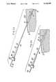
- FIG. 2ais a side elevation view of an IAB device according to the present invention showing the IAB bladder being directly inserted into the femoral common artery without an insertion sheath;
- FIG. 2bis a side elevation view partly in cross-section showing the IAB device of FIG. 1 following insertion of the IAB bladder into the femoral common artery;
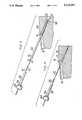
- FIG. 3is a side elevation view of an IAB device according to the present invention showing the IAB bladder being inserted into the femoral common artery using an insertion sheath;
- FIG. 4is a side elevation view partly in cross-section showing the IAB device of FIG. 3 following insertion of the IAB bladder into the femoral common artery;
- FIG. 5is a side elevation view of the IAB device of FIGS. 2a, 2b, 3 and 4 showing the hemostasis device of the present invention positioned within the insertion puncture in accordance with the IAB insertion methods of the present invention illustrated in FIGS. 2a, 2b, 3 and 4.
- FIG. 6is a cross-section of the hemostasis device according to the invention showing the hemostasis device installed on a balloon catheter.
- FIG. 1lines (a-d) the various steps employed in the Seldinger technique for inserting an IAB device percutaneously, and in FIGS. 2a through 6, the preferred embodiments of the IAB assembly with hemostasis device and method for percutaneous insertion of same according to the present invention.
- FIG. 1 line (a)shows puncture of the skin and the femoral artery using a Seldinger needle.
- FIG. 1 line (b)shows placement of a guide wire 5 into the artery through the hollow bore of the needle.
- FIG. 1 line (c)shows removal of the hypodermic needle from the artery leaving the guide wire 5 in place.
- FIG. 1 line (d)shows placement of an insertion sheath into the artery over the guide wire following dilation of the insertion site.
- FIGS. 2a, 2b, and 5there is shown the insertion of an IAB assembly with hemostasis device according to the invention into a femoral common artery through the skin using a new percutaneous insertion technique also according to the invention.
- a physician(not shown) would be positioned in the left-hand margin in relation to the various elements being described.
- proximal and distalas used herein shall refer to position a relative to that of the physician.
- the IAB assemblycomprises and IAB bladder 40 which is attached to a balloon catheter 42.
- the IABis a double lumen device with a central cannula 44 preferably of, but not limited to, the type described in U.S. Pat. No. 4,362,150, which patent is incorporated herein by reference.
- the IABcan have a wrap handle for rotation as described in the above patent or can have a fixed type configuration.
- the bladder 40Prior to insertion, the bladder 40 is wrapped about itself to reduce its diameter either by the manufacturer or by the physician.
- the balloon catheter 42may be attached at its proximal end to a rotating or fixed handle (not shown) and may also be connected in known manner to an intra-aortic balloon pumping/monitoring system (also not shown).
- hemostasis device 50is slidably mounted to balloon catheter 42 and generally comprises a the distal end of the device, a second segment 50b positioned proximally with respect to first segment 50a and formed with a neck portion 55, a transition segment 50c connecting segments 50a and 50b together, a flange 57 formed on segment 50b at the proximal end of the hemostasis device, and a cuff 60 releasably connectable to flange 57.
- the hemostasis deviceis manufactured from a resilient plastic material, such as polytetrafluoroethylene (Teflon®) or polyethylene.
- the cuff 60is manufactured from an elastomeric material such as, for example, Kraton; although no particular elastomeric material is preferred.
- first segment 50ahas a constant outside diameter which is only slightly larger than the outside diameter of catheter 42, and which is dimensioned to be as small as possible so as to pass through the opening made by the passage of balloon bladder 40 through the percutaneous insertion site and into the femoral artery.
- the outside diameter of the balloon catheteris about 10.5 French (i.e. about 0.138 inches)
- the outside diameter (A) of segment 50ais about 0.150 inches.
- the outside diameter (A) of segment 50ais about 0.142 inches.
- segment 50apreferably has a length of at least about 1/8 inch, and is configured and dimensioned to generate less initial resistance during insertion through the patient's skin so that the hemostasis device as a whole can be more easily inserted into the patient. Although the overall resistance to further insertion will increase as larger diameter segment 50b of the hemostasis device (described below) is inserted, the safe passage of segment 50a through the skin will avoid the danger of collapsing or buckling of the hemostasis device at its distal end.
- hemostasis device 50 of the present inventionis provided with a second segment 50b connected to segment 50a via a transition segment 50c.
- segment 50bhas a constant outside diameter dimensioned to be larger than the outside diameter of the wrapped balloon 40. This will enable segment 50b to fill the opening in the patient's skin created by the insertion of balloon 40 into the patient's femoral artery and thereby stop bleeding from the femoral artery at the insertion site.
- the outside diameter of segment 50bis preferably about 0.169 inches. This will provide adequate hemostasis capability for all commercially available IAB assemblies; the largest being a 50 cc assembly wherein the outside diameter of the wrapped balloon is about 0.162 inches.
- transition segment 50cis configured and dimensioned so as to allow essentially immediate transition from first segment 50a to second segment 50b during insertion of hemostasis device 50 into the percutaneous insertion site opening, yet at the same time minimize any resistance encountered during insertion of larger diameter segment 50b through the patient's skin.
- transition segment 50chas a tapered configuration and a length of about 1/8 inch measured linearly from the end of segment 50a to the beginning of segment 50b.
- the angle of taper for segment 50cwill vary in accordance with the dimensions of segments 50a and 50b employed, it is preferred that transition segment 50c be tapered in a manner so as to provide the smoothest and quickest transition from first segment 50a to second segment 50b during the insertion process.
- transition segment 50cdoes not perform a hemostasis function, it may, in accordance with the invention, be omitted from the hemostasis device structure (with second segment 50b immediately following first segment 50a). Such an arrangement, however, is less preferred as it will result in increased resistance to insertion of the hemostasis device into the patient.
- the length of segment 50bis about 2.75 inches, thereby giving hemostasis device 50 an overall length (T) between distal end 52 and proximal end 54 of preferably about 3.0 inches.
- Toverall length between distal end 52 and proximal end 54 of preferably about 3.0 inches.
- the inside diameter (I) of hemostasis device 50can be about the same throughout its entire length (as shown in FIG. 6), or can vary in accordance with the configuration of the outside of hemostasis device 50.
- the inside diameter of device 50is preferably sized to provide a close clearance 58 between the inside of the hemostasis device 50 at distal end 52 and the outside of the balloon catheter 42.
- the inside diameter (I) of hemostasis device 50 at distal end 52is between about 2 to 3 thousandths of an inch larger than the outside diameter of the balloon catheter 42 to allow for manufacturing tolerance.
- the inside diameter (I) of the hemostasis device 50 at the distal end 52is about 0.140 inches to provide a clearance 58 of about 0.002 inches between the hemostasis device and the catheter.
- This close fit clearance 58permits the outside diameter of hemostasis device 50 to be as small as possible at the distal end 52 with the balloon catheter 42 providing structural support for the hemostasis device 50 during insertion to prevent an accordion effect from occurring at distal end 52.
- the resilient, low-friction nature of the hemostasis device materialallows the device to be easily slidably advanced along the catheter in either a distal or proximal direction substantially without loosening the interference fit between the parts.
- hemostasis device 50is provided at its proximal end with a neck 55 and flange 57, each formed on second segment 50b. As here embodied, neck 55 and flange 57 are held within a cuff member 60. As shown in FIG. 6, cuff 60 is sized to provide a close clearance 64 between the cuff and neck 55 of the hemostasis device. Additionally, cuff 60 is sized to provide a close clearance 62 between the cuff and balloon catheter 42. In this manner, cuff 60 is able to seal the proximal end of hemostasis device 50 against backflow of blood through the device after it has been inserted into the femoral artery. Close clearance 62 also precludes slippage of cuff 60 and, in turn, hemostasis device 50 along catheter 42 due to arterial pressure and the like.
- a small hypodermic needle(not shown) is inserted through the skin 20 of a patient to perforate or puncture the femoral artery 10.
- a guide wire 5sufficient in length to reach the central aorta (e.g. up to about 170-190 cm or longer) is fed into the artery 10 by passing the guide wire through the center of the hollow hypodermic needle.
- the hypodermic needleis removed leaving the guide wire 5 in place.
- One or more progressively larger dilators(preferably a single expanding, e.g. Grunzig type dilator) is then placed over the guide wire and advanced through the perforated skin 20 and into the artery 10 in order to expand the hole to achieve an opening large enough to permit the passage of the wrapped IAB bladder 40.
- a progressively larger dilatorspreferably a single expanding, e.g. Grunzig type dilator
- the holeshould be dilated to approximately 10 French in diameter.
- the IAB bladder 40 in its wrapped conditionhas a larger outside diameter than the IAB catheter 42.
- the IAB bladder 40will dilate the insertion site to a larger diameter than that of the catheter 42.
- the insertion site 8may have an opening which, due to some inelasticity in the skin, has not completely closed around the catheter 42. This condition may result in uncontrollable bleeding from the insertion site.
- hemostasis device 50is slidably advanced in a distal direction along catheter 42 so as to insert first segment 50a thereof into opening 14 in the wall of femoral artery 10 made by passage of the IAB balloon bladder thereinto. Hemostasis device 50 is further advanced into the femoral artery until segment 50b thereof fills opening 14 (see FIG. 5). In this position, the outside diameter of segment 50b will sufficiently fill opening 14 so as to provide elastic, sealing contact between the skin opening and segment 50b, and thereby stop bleeding which might have resulted after insertion of the IAB device.
- the configuration and dimensions of the hemostasis device(described above) control bleeding without restricting good blood flow through artery 10 to any great degree. Moreover, any residual backflow of blood up through device 50 during the insertion process will be prevented from spurting out of the hemostasis device via cuff member 60.
- FIG. 3shows, from left to right, a hemostasis device 50 slidably connected to a balloon catheter 42, a tear-away insertion sheath 30, an IAB bladder 40, and a femoral common artery 10.
- an IAB deviceis inserted into the femoral common artery 10 through skin 20 using the percutaneous Seldinger technique.
- bladder 40Prior to insertion, bladder 40 is wrapped about itself to reduce its diameter.
- the balloon catheter 42may be attached at its proximal end to a wrap handle (not shown) and may also be connected to an intra-aortic balloon pumping/monitoring system (also not shown).
- a tear-away insertion sheath 30is inserted into artery 10 through opening 14.
- the tear-away insertion sheath 30may have a tear line 32 which permits sheath 30 to be torn therealong and removed from insertion site 8 once the balloon 40 has been inserted into the aorta.
- insertion sheath 30may be formed by linear extrusion (as is known in the art) to facilitate tearing thereof for removal purposes.
- an intra-aortic balloon 40is passed through the insertion sheath and into artery 10 using the following percutaneous insertion (Seldinger) technique.
- a small hypodermic needle(not shown) is inserted through the skin 20 of a patient to perforate or puncture the artery 10.
- a guide wire(also not shown) is fed into the artery 10 by passing the guide wire through the center of the hollow hypodermic needle. The hypodermic needle is then removed leaving the wire in place.
- a dilator(also not shown) is placed over the guide wire and advanced through the perforated skin 20 and into artery 10 in order to dilate (that is enlarge) the artery 10 and create opening 14.
- the dilatoris then removed and a series of larger dilators (not shown) are then fed over the guide wire and into artery 10 to continue the dilation procedure.
- the insertion sheath 30is inserted through the opening 14 and into the artery and the last dilator is removed leaving the insertion sheath 30 extending through the opening 14 and available for insertion of the IAB device over the guide wire and into the patient without requiring surgery.
- the tear-away insertion sheath 30is removed. Upon removal of the insertion sheath, however, the wall of the femoral artery may not completely constrict around the balloon catheter 42 resulting in uncontrolled bleeding at the insertion site. In order to control such bleeding, the hemostasis device 50 is slid down the balloon catheter 42 towards insertion site 8 and partially into the opening 14.
- hemostasis device 50is inserted into the opening 14 in the wall of artery 10 until the outside diameter of segment 50b fills opening 14 (see FIG. 5). In this position, elastic sealing contact is provided between the patient's skin opening and segment 50b, thereby preventing bleeding at the insertion site without restricting good blood flow through the artery 10 to any great degree. Any residual backflow of blood up through hemostasis device 50 during the insertion thereof will be prevented from spurting out of the hemostasis device 50 via cuff member 60.
Landscapes
- Health & Medical Sciences (AREA)
- Life Sciences & Earth Sciences (AREA)
- Heart & Thoracic Surgery (AREA)
- Biomedical Technology (AREA)
- Engineering & Computer Science (AREA)
- Anesthesiology (AREA)
- Pulmonology (AREA)
- Hematology (AREA)
- Animal Behavior & Ethology (AREA)
- General Health & Medical Sciences (AREA)
- Public Health (AREA)
- Veterinary Medicine (AREA)
- Biophysics (AREA)
- Surgical Instruments (AREA)
- Media Introduction/Drainage Providing Device (AREA)
Abstract
Description
Claims (11)
Priority Applications (1)
| Application Number | Priority Date | Filing Date | Title |
|---|---|---|---|
| US07/610,285US5120299A (en) | 1987-05-22 | 1990-11-07 | Intra-aortic balloon assembly with hemostasis device |
Applications Claiming Priority (2)
| Application Number | Priority Date | Filing Date | Title |
|---|---|---|---|
| US5318387A | 1987-05-22 | 1987-05-22 | |
| US07/610,285US5120299A (en) | 1987-05-22 | 1990-11-07 | Intra-aortic balloon assembly with hemostasis device |
Related Parent Applications (1)
| Application Number | Title | Priority Date | Filing Date |
|---|---|---|---|
| US5318387AContinuation-In-Part | 1986-10-30 | 1987-05-22 |
Publications (1)
| Publication Number | Publication Date |
|---|---|
| US5120299Atrue US5120299A (en) | 1992-06-09 |
Family
ID=26731550
Family Applications (1)
| Application Number | Title | Priority Date | Filing Date |
|---|---|---|---|
| US07/610,285Expired - LifetimeUS5120299A (en) | 1987-05-22 | 1990-11-07 | Intra-aortic balloon assembly with hemostasis device |
Country Status (1)
| Country | Link |
|---|---|
| US (1) | US5120299A (en) |
Cited By (30)
| Publication number | Priority date | Publication date | Assignee | Title |
|---|---|---|---|---|
| US5334160A (en)* | 1992-05-04 | 1994-08-02 | Scimed Life Systems, Inc. | Intravascular catheter with sleeve and method for use thereof |
| US5431639A (en)* | 1993-08-12 | 1995-07-11 | Boston Scientific Corporation | Treating wounds caused by medical procedures |
| US5947953A (en)* | 1997-08-06 | 1999-09-07 | Hemocleanse, Inc. | Splittable multiple catheter assembly and methods of inserting the same |
| US20030125619A1 (en)* | 2001-12-31 | 2003-07-03 | Cardiac Pacemakers, Inc. | Telescoping guide catheter with peel-away outer sheath |
| US20040010265A1 (en)* | 2002-05-31 | 2004-01-15 | Wilson-Cook Medical, Inc. | Stent introducer apparatus |
| US20040113542A1 (en)* | 2002-12-11 | 2004-06-17 | Applied Materials, Inc. | Low temperature process for passivation applications |
| US20050054990A1 (en)* | 2003-09-08 | 2005-03-10 | Joanna Graft | Split-tip catheter divider |
| US20050182387A1 (en)* | 2004-02-13 | 2005-08-18 | Cardiac Pacemakers, Inc. | Peel-away catheter shaft |
| US20080009803A1 (en)* | 2000-06-01 | 2008-01-10 | Twincath, Llc | Multi-lumen catheter and methods for making the catheter |
| US7393339B2 (en) | 2003-02-21 | 2008-07-01 | C. R. Bard, Inc. | Multi-lumen catheter with separate distal tips |
| USRE40913E1 (en) | 2000-06-01 | 2009-09-08 | Medical Components, Inc. | Multilumen catheter assembly and methods for making and inserting the same |
| US8021321B2 (en) | 2002-02-07 | 2011-09-20 | C. R. Bard, Inc. | Split tip dialysis catheter |
| US8066660B2 (en) | 2007-10-26 | 2011-11-29 | C. R. Bard, Inc. | Split-tip catheter including lateral distal openings |
| US8092415B2 (en) | 2007-11-01 | 2012-01-10 | C. R. Bard, Inc. | Catheter assembly including triple lumen tip |
| US8206371B2 (en) | 2003-05-27 | 2012-06-26 | Bard Access Systems, Inc. | Methods and apparatus for inserting multi-lumen split-tip catheters into a blood vessel |
| US8292841B2 (en) | 2007-10-26 | 2012-10-23 | C. R. Bard, Inc. | Solid-body catheter including lateral distal openings |
| US8500939B2 (en) | 2007-10-17 | 2013-08-06 | Bard Access Systems, Inc. | Manufacture of split tip catheters |
| US8540618B2 (en) | 2003-01-31 | 2013-09-24 | L-Vad Technology, Inc. | Stable aortic blood pump implant |
| US20140005768A1 (en)* | 2010-08-17 | 2014-01-02 | St. Jude Medical, Inc. | Sleeve for facilitating movement of a transfemoral catheter |
| US8992454B2 (en) | 2004-06-09 | 2015-03-31 | Bard Access Systems, Inc. | Splitable tip catheter with bioresorbable adhesive |
| USD748252S1 (en) | 2013-02-08 | 2016-01-26 | C. R. Bard, Inc. | Multi-lumen catheter tip |
| US9370422B2 (en) | 2011-07-28 | 2016-06-21 | St. Jude Medical, Inc. | Expandable radiopaque marker for transcatheter aortic valve implantation |
| US9439795B2 (en) | 2010-09-17 | 2016-09-13 | St. Jude Medical, Cardiology Division, Inc. | Retainers for transcatheter heart valve delivery systems |
| US9480561B2 (en) | 2012-06-26 | 2016-11-01 | St. Jude Medical, Cardiology Division, Inc. | Apparatus and method for aortic protection and TAVI planar alignment |
| US9579485B2 (en) | 2007-11-01 | 2017-02-28 | C. R. Bard, Inc. | Catheter assembly including a multi-lumen configuration |
| US9694122B2 (en)* | 2003-01-31 | 2017-07-04 | L-Vad Technology, Inc. | Rigid body aortic blood pump implant |
| US9918837B2 (en) | 2012-06-29 | 2018-03-20 | St. Jude Medical, Cardiology Division, Inc. | System to assist in the release of a collapsible stent from a delivery device |
| US10258768B2 (en) | 2014-07-14 | 2019-04-16 | C. R. Bard, Inc. | Apparatuses, systems, and methods for inserting catheters having enhanced stiffening and guiding features |
| US10398550B2 (en) | 2013-09-12 | 2019-09-03 | St. Jude Medical, Cardiology Division, Inc. | Atraumatic interface in an implant delivery device |
| US10667907B2 (en) | 2016-05-13 | 2020-06-02 | St. Jude Medical, Cardiology Division, Inc. | Systems and methods for device implantation |
Citations (6)
| Publication number | Priority date | Publication date | Assignee | Title |
|---|---|---|---|---|
| US3921631A (en)* | 1972-06-21 | 1975-11-25 | Vicra Sterile Inc | Catheter insertion device and method of catheter introduction |
| US4473067A (en)* | 1982-04-28 | 1984-09-25 | Peter Schiff | Introducer assembly for intra-aortic balloons and the like incorporating a sliding, blood-tight seal |
| US4738658A (en)* | 1986-09-19 | 1988-04-19 | Aries Medical Incorporated | Tapered hemostatic device for use in conjunction with a catheter for alleviating blood leakage and method for using same |
| US4850960A (en)* | 1987-07-08 | 1989-07-25 | Joseph Grayzel | Diagonally tapered, bevelled tip introducing catheter and sheath and method for insertion |
| US4883461A (en)* | 1987-05-15 | 1989-11-28 | Interface Biomedical Laboratories Corp. | Safety needle sheath in anti-reflux catheter having novel valve means |
| US4897077A (en)* | 1987-05-22 | 1990-01-30 | Kontron Inc. | Method of inserting an IAB device into the body |
- 1990
- 1990-11-07USUS07/610,285patent/US5120299A/ennot_activeExpired - Lifetime
Patent Citations (6)
| Publication number | Priority date | Publication date | Assignee | Title |
|---|---|---|---|---|
| US3921631A (en)* | 1972-06-21 | 1975-11-25 | Vicra Sterile Inc | Catheter insertion device and method of catheter introduction |
| US4473067A (en)* | 1982-04-28 | 1984-09-25 | Peter Schiff | Introducer assembly for intra-aortic balloons and the like incorporating a sliding, blood-tight seal |
| US4738658A (en)* | 1986-09-19 | 1988-04-19 | Aries Medical Incorporated | Tapered hemostatic device for use in conjunction with a catheter for alleviating blood leakage and method for using same |
| US4883461A (en)* | 1987-05-15 | 1989-11-28 | Interface Biomedical Laboratories Corp. | Safety needle sheath in anti-reflux catheter having novel valve means |
| US4897077A (en)* | 1987-05-22 | 1990-01-30 | Kontron Inc. | Method of inserting an IAB device into the body |
| US4850960A (en)* | 1987-07-08 | 1989-07-25 | Joseph Grayzel | Diagonally tapered, bevelled tip introducing catheter and sheath and method for insertion |
Cited By (72)
| Publication number | Priority date | Publication date | Assignee | Title |
|---|---|---|---|---|
| US5334160A (en)* | 1992-05-04 | 1994-08-02 | Scimed Life Systems, Inc. | Intravascular catheter with sleeve and method for use thereof |
| US5431639A (en)* | 1993-08-12 | 1995-07-11 | Boston Scientific Corporation | Treating wounds caused by medical procedures |
| US5947953A (en)* | 1997-08-06 | 1999-09-07 | Hemocleanse, Inc. | Splittable multiple catheter assembly and methods of inserting the same |
| US6190349B1 (en) | 1997-08-06 | 2001-02-20 | Hemocleanse, Inc. | Splittable multiple catheter assembly and methods for inserting the same |
| US20080009803A1 (en)* | 2000-06-01 | 2008-01-10 | Twincath, Llc | Multi-lumen catheter and methods for making the catheter |
| US11058849B2 (en) | 2000-06-01 | 2021-07-13 | Medical Components, Inc. | Multi-lumen catheter |
| US7981093B2 (en) | 2000-06-01 | 2011-07-19 | Medical Components, Inc. | Methods of making a multilumen catheter assembly |
| USRE40913E1 (en) | 2000-06-01 | 2009-09-08 | Medical Components, Inc. | Multilumen catheter assembly and methods for making and inserting the same |
| US20050065561A1 (en)* | 2001-12-31 | 2005-03-24 | Cardiac Pacemakers, Inc. | Methods of using a telescoping guide catheter with peel-away outer sheath |
| US6979319B2 (en) | 2001-12-31 | 2005-12-27 | Cardiac Pacemakers, Inc. | Telescoping guide catheter with peel-away outer sheath |
| US7117039B2 (en) | 2001-12-31 | 2006-10-03 | Cardiac Pacemakers, Inc. | Methods of using a telescoping guide catheter with peel-away outer sheath |
| US20070021812A1 (en)* | 2001-12-31 | 2007-01-25 | Cardiac Pacemakers, Inc. | Telescoping guide catheter with peel-away outer sheath |
| US20030125619A1 (en)* | 2001-12-31 | 2003-07-03 | Cardiac Pacemakers, Inc. | Telescoping guide catheter with peel-away outer sheath |
| US8126570B2 (en) | 2001-12-31 | 2012-02-28 | Cardiac Pacemakers, Inc. | Telescoping guide catheter with peel-away outer sheath |
| US7697996B2 (en) | 2001-12-31 | 2010-04-13 | Cardiac Pacemakers, Inc. | Telescoping guide catheter with peel-away outer sheath |
| US20100198194A1 (en)* | 2001-12-31 | 2010-08-05 | Manning Frank E | Telescoping Guide Catheter with Peel-Away Outer Sheath |
| US8021321B2 (en) | 2002-02-07 | 2011-09-20 | C. R. Bard, Inc. | Split tip dialysis catheter |
| US7314481B2 (en) | 2002-05-31 | 2008-01-01 | Wilson-Cook Medical Inc. | Stent introducer apparatus |
| US20040010265A1 (en)* | 2002-05-31 | 2004-01-15 | Wilson-Cook Medical, Inc. | Stent introducer apparatus |
| US20040113542A1 (en)* | 2002-12-11 | 2004-06-17 | Applied Materials, Inc. | Low temperature process for passivation applications |
| US9433715B2 (en) | 2003-01-31 | 2016-09-06 | L-Vad Technology, Inc. | Stable aortic blood pump implant |
| US8540618B2 (en) | 2003-01-31 | 2013-09-24 | L-Vad Technology, Inc. | Stable aortic blood pump implant |
| US9694122B2 (en)* | 2003-01-31 | 2017-07-04 | L-Vad Technology, Inc. | Rigid body aortic blood pump implant |
| US7393339B2 (en) | 2003-02-21 | 2008-07-01 | C. R. Bard, Inc. | Multi-lumen catheter with separate distal tips |
| US8152951B2 (en) | 2003-02-21 | 2012-04-10 | C. R. Bard, Inc. | Multi-lumen catheter with separate distal tips |
| US9387304B2 (en) | 2003-02-21 | 2016-07-12 | C.R. Bard, Inc. | Multi-lumen catheter with separate distal tips |
| US8808227B2 (en) | 2003-02-21 | 2014-08-19 | C. R. Bard, Inc. | Multi-lumen catheter with separate distal tips |
| US10806895B2 (en) | 2003-05-27 | 2020-10-20 | Bard Access Systems, Inc. | Methods and apparatus for inserting multi-lumen split-tip catheters into a blood vessel |
| US8206371B2 (en) | 2003-05-27 | 2012-06-26 | Bard Access Systems, Inc. | Methods and apparatus for inserting multi-lumen split-tip catheters into a blood vessel |
| US10105514B2 (en) | 2003-05-27 | 2018-10-23 | Bard Access Systems, Inc. | Methods and apparatus for inserting multi-lumen split-tip catheters into a blood vessel |
| US8597275B2 (en) | 2003-05-27 | 2013-12-03 | Bard Access Systems, Inc. | Methods and apparatus for inserting multi-lumen split-tip catheters into a blood vessel |
| US9572956B2 (en) | 2003-05-27 | 2017-02-21 | Bard Access Systems, Inc. | Methods and apparatus for inserting multi-lumen split-tip catheters into a blood vessel |
| US20050054990A1 (en)* | 2003-09-08 | 2005-03-10 | Joanna Graft | Split-tip catheter divider |
| US20050182387A1 (en)* | 2004-02-13 | 2005-08-18 | Cardiac Pacemakers, Inc. | Peel-away catheter shaft |
| US9669149B2 (en) | 2004-06-09 | 2017-06-06 | Bard Access Systems, Inc. | Splitable tip catheter with bioresorbable adhesive |
| US8992454B2 (en) | 2004-06-09 | 2015-03-31 | Bard Access Systems, Inc. | Splitable tip catheter with bioresorbable adhesive |
| US9782535B2 (en) | 2004-06-09 | 2017-10-10 | Bard Access Systems, Inc. | Splitable tip catheter with bioresorbable adhesive |
| US8500939B2 (en) | 2007-10-17 | 2013-08-06 | Bard Access Systems, Inc. | Manufacture of split tip catheters |
| US9174019B2 (en) | 2007-10-26 | 2015-11-03 | C. R. Bard, Inc. | Solid-body catheter including lateral distal openings |
| US8540661B2 (en) | 2007-10-26 | 2013-09-24 | C. R. Bard, Inc. | Solid-body catheter including lateral distal openings |
| US11338075B2 (en) | 2007-10-26 | 2022-05-24 | C. R. Bard, Inc. | Split-tip catheter including lateral distal openings |
| US9233200B2 (en) | 2007-10-26 | 2016-01-12 | C.R. Bard, Inc. | Split-tip catheter including lateral distal openings |
| US11260161B2 (en) | 2007-10-26 | 2022-03-01 | C. R. Bard, Inc. | Solid-body catheter including lateral distal openings |
| US8066660B2 (en) | 2007-10-26 | 2011-11-29 | C. R. Bard, Inc. | Split-tip catheter including lateral distal openings |
| US12076475B2 (en) | 2007-10-26 | 2024-09-03 | C. R. Bard, Inc. | Split-tip catheter including lateral distal openings |
| US10258732B2 (en) | 2007-10-26 | 2019-04-16 | C. R. Bard, Inc. | Split-tip catheter including lateral distal openings |
| US8292841B2 (en) | 2007-10-26 | 2012-10-23 | C. R. Bard, Inc. | Solid-body catheter including lateral distal openings |
| US8696614B2 (en) | 2007-10-26 | 2014-04-15 | C. R. Bard, Inc. | Split-tip catheter including lateral distal openings |
| US10207043B2 (en) | 2007-10-26 | 2019-02-19 | C. R. Bard, Inc. | Solid-body catheter including lateral distal openings |
| US9610422B2 (en) | 2007-11-01 | 2017-04-04 | C. R. Bard, Inc. | Catheter assembly |
| US8092415B2 (en) | 2007-11-01 | 2012-01-10 | C. R. Bard, Inc. | Catheter assembly including triple lumen tip |
| US8894601B2 (en) | 2007-11-01 | 2014-11-25 | C. R. Bard, Inc. | Catheter assembly including triple lumen tip |
| US11918758B2 (en) | 2007-11-01 | 2024-03-05 | C. R. Bard, Inc. | Catheter assembly including a multi-lumen configuration |
| US10518064B2 (en) | 2007-11-01 | 2019-12-31 | C. R. Bard, Inc. | Catheter assembly including a multi-lumen configuration |
| US9579485B2 (en) | 2007-11-01 | 2017-02-28 | C. R. Bard, Inc. | Catheter assembly including a multi-lumen configuration |
| US10130470B2 (en)* | 2010-08-17 | 2018-11-20 | St. Jude Medical, Llc | Sleeve for facilitating movement of a transfemoral catheter |
| US20140005768A1 (en)* | 2010-08-17 | 2014-01-02 | St. Jude Medical, Inc. | Sleeve for facilitating movement of a transfemoral catheter |
| US10799351B2 (en) | 2010-09-17 | 2020-10-13 | St. Jude Medical, Cardiology Division, Inc. | Retainers for transcatheter heart valve delivery systems |
| US9439795B2 (en) | 2010-09-17 | 2016-09-13 | St. Jude Medical, Cardiology Division, Inc. | Retainers for transcatheter heart valve delivery systems |
| US9370422B2 (en) | 2011-07-28 | 2016-06-21 | St. Jude Medical, Inc. | Expandable radiopaque marker for transcatheter aortic valve implantation |
| US10028830B2 (en) | 2011-07-28 | 2018-07-24 | St. Jude Medical, Llc | Expandable radiopaque marker for transcatheter aortic valve implantation |
| US10441418B2 (en) | 2012-06-26 | 2019-10-15 | St. Jude Medical, Cardiology Division, Inc. | Apparatus and method for aortic protection and tavi planar alignment |
| US9480561B2 (en) | 2012-06-26 | 2016-11-01 | St. Jude Medical, Cardiology Division, Inc. | Apparatus and method for aortic protection and TAVI planar alignment |
| US9918837B2 (en) | 2012-06-29 | 2018-03-20 | St. Jude Medical, Cardiology Division, Inc. | System to assist in the release of a collapsible stent from a delivery device |
| US12295843B2 (en) | 2012-06-29 | 2025-05-13 | St. Jude Medical, Cardiology Division, Inc. | System to assist in the release of a collapsible stent from a delivery device |
| US11026789B2 (en) | 2012-06-29 | 2021-06-08 | St. Jude Medical, Cardiology Division, Inc. | System to assist in the release of a collapsible stent from a delivery device |
| US11612483B2 (en) | 2012-06-29 | 2023-03-28 | St. Jude Medical, Cardiology Division, Ine. | System to assist in the release of a collapsible stent from a delivery device |
| USD748252S1 (en) | 2013-02-08 | 2016-01-26 | C. R. Bard, Inc. | Multi-lumen catheter tip |
| US10398550B2 (en) | 2013-09-12 | 2019-09-03 | St. Jude Medical, Cardiology Division, Inc. | Atraumatic interface in an implant delivery device |
| US10258768B2 (en) | 2014-07-14 | 2019-04-16 | C. R. Bard, Inc. | Apparatuses, systems, and methods for inserting catheters having enhanced stiffening and guiding features |
| US10857330B2 (en) | 2014-07-14 | 2020-12-08 | C. R. Bard, Inc. | Apparatuses, systems, and methods for inserting catheters having enhanced stiffening and guiding features |
| US10667907B2 (en) | 2016-05-13 | 2020-06-02 | St. Jude Medical, Cardiology Division, Inc. | Systems and methods for device implantation |
Similar Documents
| Publication | Publication Date | Title |
|---|---|---|
| US5120299A (en) | Intra-aortic balloon assembly with hemostasis device | |
| US4327709A (en) | Apparatus and method for the percutaneous introduction of intra-aortic balloons into the human body | |
| US4804365A (en) | Vascular cannulae for transfemoral cardiopulmonary bypass and method of use | |
| US5125904A (en) | Splittable hemostatic valve and sheath and the method for using the same | |
| US5158545A (en) | Diameter expansion cannula | |
| US4862891A (en) | Device for sequential percutaneous dilation | |
| US5437631A (en) | Percutaneous introducer set and method for sealing puncture wounds | |
| AU767637B2 (en) | Improved intra-aortic balloon catheter and insertion sheath | |
| US4738658A (en) | Tapered hemostatic device for use in conjunction with a catheter for alleviating blood leakage and method for using same | |
| US4897077A (en) | Method of inserting an IAB device into the body | |
| US4540404A (en) | Balloon catheter with intrinsic introducer for percutaneous insertion into a blood vessel over a guide wire, and method of use | |
| US7722568B2 (en) | Expandable intra-aortic balloon pump sheath | |
| US5167634A (en) | Peelable sheath with hub connector | |
| US5078685A (en) | Catheter with exterior tunnel member | |
| US4921483A (en) | Angioplasty catheter | |
| US20060217664A1 (en) | Telescoping vascular dilator | |
| JPH06502327A (en) | Percutaneous transseptal left atrial cannulation system | |
| JP2005161065A (en) | Method and apparatus for catheterization access | |
| US20020193822A1 (en) | Externally positioned medical dilator | |
| US5772631A (en) | Procedure for alleviating arterial obstruction | |
| WO2025098390A1 (en) | Venous catheter having automatically unfolding member | |
| EP0265864B1 (en) | Hemostasis sheath | |
| US6179825B1 (en) | Oval vascular catheter | |
| US20050234497A1 (en) | Externally positioned medical dilator | |
| CN113520539B (en) | Catheter sheath for central venous catheter and auxiliary device |
Legal Events
| Date | Code | Title | Description |
|---|---|---|---|
| AS | Assignment | Owner name:KONTRON INSTRUMENTS, INC., MASSACHUSETTS Free format text:ASSIGNMENT OF ASSIGNORS INTEREST.;ASSIGNOR:LOMBARDI, EDWARD J.;REEL/FRAME:006040/0504 Effective date:19920302 | |
| STCF | Information on status: patent grant | Free format text:PATENTED CASE | |
| CC | Certificate of correction | ||
| AS | Assignment | Owner name:SHAWMUT BANK, N.A., MASSACHUSETTS Free format text:SECURITY INTEREST;ASSIGNOR:KONTRON INSTRUMENTS, INC.;REEL/FRAME:006663/0651 Effective date:19930730 | |
| AS | Assignment | Owner name:KONTRON INSTRUMENTS, INC., MASSACHUSETTS Free format text:TERMINATION/RELEASE;ASSIGNOR:SHAWMUT BANK, N.A.;REEL/FRAME:006842/0949 Effective date:19940131 | |
| FEPP | Fee payment procedure | Free format text:PAYOR NUMBER ASSIGNED (ORIGINAL EVENT CODE: ASPN); ENTITY STATUS OF PATENT OWNER: LARGE ENTITY | |
| FPAY | Fee payment | Year of fee payment:4 | |
| AS | Assignment | Owner name:ARROW INTERVENTIONAL, INC., ENGLAND Free format text:SECURITY INTEREST;ASSIGNOR:KONTRON INSTRUMENT INCORPORATED;REEL/FRAME:007991/0444 Effective date:19960227 | |
| AS | Assignment | Owner name:ARROW INTERNATIONAL INVESTMENT CORPORATION, DELAWA Free format text:ASSIGNMENT OF ASSIGNORS INTEREST;ASSIGNOR:ARROW INTERVENTIONAL, INC.;REEL/FRAME:008077/0661 Effective date:19960430 | |
| AS | Assignment | Owner name:ARROW INTERVENTIONAL, INC., MASSACHUSETTS Free format text:ASSIGNMENT OF ASSIGNORS INTEREST;ASSIGNOR:ARROW INTERNATIONAL INVESTMENT CORP.;REEL/FRAME:009015/0349 Effective date:19980204 | |
| FPAY | Fee payment | Year of fee payment:8 | |
| FPAY | Fee payment | Year of fee payment:12 |