US5120175A - Shape memory alloy fastener - Google Patents
Shape memory alloy fastenerDownload PDFInfo
- Publication number
- US5120175A US5120175AUS07/730,222US73022291AUS5120175AUS 5120175 AUS5120175 AUS 5120175AUS 73022291 AUS73022291 AUS 73022291AUS 5120175 AUS5120175 AUS 5120175A
- Authority
- US
- United States
- Prior art keywords
- fastener
- shape
- shank
- opening
- trained
- Prior art date
- Legal status (The legal status is an assumption and is not a legal conclusion. Google has not performed a legal analysis and makes no representation as to the accuracy of the status listed.)
- Expired - Lifetime
Links
- 229910001285shape-memory alloyInorganic materials0.000titleclaimsabstractdescription38
- 230000009466transformationEffects0.000claimsabstractdescription48
- 238000003780insertionMethods0.000claimsabstractdescription30
- 230000037431insertionEffects0.000claimsabstractdescription30
- 230000008602contractionEffects0.000claimsabstractdescription10
- 238000000034methodMethods0.000claimsdescription19
- 238000010438heat treatmentMethods0.000claimsdescription11
- 229910001000nickel titaniumInorganic materials0.000claimsdescription4
- PXHVJJICTQNCMI-UHFFFAOYSA-NNickelChemical compound[Ni]PXHVJJICTQNCMI-UHFFFAOYSA-N0.000claims4
- 238000001816coolingMethods0.000claims3
- RYGMFSIKBFXOCR-UHFFFAOYSA-NCopperChemical compound[Cu]RYGMFSIKBFXOCR-UHFFFAOYSA-N0.000claims2
- RTAQQCXQSZGOHL-UHFFFAOYSA-NTitaniumChemical compound[Ti]RTAQQCXQSZGOHL-UHFFFAOYSA-N0.000claims2
- 239000010949copperSubstances0.000claims2
- 229910052802copperInorganic materials0.000claims2
- 229910052759nickelInorganic materials0.000claims2
- 239000010936titaniumSubstances0.000claims2
- 229910052719titaniumInorganic materials0.000claims2
- 229910000990Ni alloyInorganic materials0.000claims1
- HZEWFHLRYVTOIW-UHFFFAOYSA-N[Ti].[Ni]Chemical compound[Ti].[Ni]HZEWFHLRYVTOIW-UHFFFAOYSA-N0.000claims1
- 239000000463materialSubstances0.000abstractdescription8
- 229910052782aluminiumInorganic materials0.000abstractdescription5
- XAGFODPZIPBFFR-UHFFFAOYSA-NaluminiumChemical compound[Al]XAGFODPZIPBFFR-UHFFFAOYSA-N0.000abstractdescription5
- 229910045601alloyInorganic materials0.000description10
- 239000000956alloySubstances0.000description10
- 229910000734martensiteInorganic materials0.000description6
- 238000000137annealingMethods0.000description4
- 238000009434installationMethods0.000description4
- 238000004519manufacturing processMethods0.000description4
- 238000012549trainingMethods0.000description4
- 238000013461designMethods0.000description3
- HLXZNVUGXRDIFK-UHFFFAOYSA-Nnickel titaniumChemical compound[Ti].[Ti].[Ti].[Ti].[Ti].[Ti].[Ti].[Ti].[Ti].[Ti].[Ti].[Ni].[Ni].[Ni].[Ni].[Ni].[Ni].[Ni].[Ni].[Ni].[Ni].[Ni].[Ni].[Ni].[Ni]HLXZNVUGXRDIFK-UHFFFAOYSA-N0.000description3
- 229920003023plasticPolymers0.000description3
- 230000008569processEffects0.000description3
- -1copper-aluminum-nickelChemical compound0.000description2
- 238000005242forgingMethods0.000description2
- 229910052751metalInorganic materials0.000description2
- 239000002184metalSubstances0.000description2
- 230000002441reversible effectEffects0.000description2
- 238000005096rolling processMethods0.000description2
- 229910000799K alloyInorganic materials0.000description1
- 229910018054Ni-CuInorganic materials0.000description1
- 229910018481Ni—CuInorganic materials0.000description1
- 229910001069Ti alloyInorganic materials0.000description1
- UXZUCXCKBOYJDF-UHFFFAOYSA-N[Ti].[Co].[Ni]Chemical compound[Ti].[Co].[Ni]UXZUCXCKBOYJDF-UHFFFAOYSA-N0.000description1
- 230000009471actionEffects0.000description1
- 238000013459approachMethods0.000description1
- 230000009286beneficial effectEffects0.000description1
- 230000015572biosynthetic processEffects0.000description1
- 230000007123defenseEffects0.000description1
- 238000005304joiningMethods0.000description1
- 238000003754machiningMethods0.000description1
- 238000000465mouldingMethods0.000description1
- 238000004663powder metallurgyMethods0.000description1
- 125000000391vinyl groupChemical group[H]C([*])=C([H])[H]0.000description1
- 229920002554vinyl polymerPolymers0.000description1
- 239000011800void materialSubstances0.000description1
Images


Classifications
- F—MECHANICAL ENGINEERING; LIGHTING; HEATING; WEAPONS; BLASTING
- F16—ENGINEERING ELEMENTS AND UNITS; GENERAL MEASURES FOR PRODUCING AND MAINTAINING EFFECTIVE FUNCTIONING OF MACHINES OR INSTALLATIONS; THERMAL INSULATION IN GENERAL
- F16B—DEVICES FOR FASTENING OR SECURING CONSTRUCTIONAL ELEMENTS OR MACHINE PARTS TOGETHER, e.g. NAILS, BOLTS, CIRCLIPS, CLAMPS, CLIPS OR WEDGES; JOINTS OR JOINTING
- F16B19/00—Bolts without screw-thread; Pins, including deformable elements; Rivets
- F16B19/04—Rivets; Spigots or the like fastened by riveting
- F16B19/06—Solid rivets made in one piece
- F—MECHANICAL ENGINEERING; LIGHTING; HEATING; WEAPONS; BLASTING
- F27—FURNACES; KILNS; OVENS; RETORTS
- F27D—DETAILS OR ACCESSORIES OF FURNACES, KILNS, OVENS OR RETORTS, IN SO FAR AS THEY ARE OF KINDS OCCURRING IN MORE THAN ONE KIND OF FURNACE
- F27D1/00—Casings; Linings; Walls; Roofs
- F27D1/14—Supports for linings
- F27D1/145—Assembling elements
- C—CHEMISTRY; METALLURGY
- C08—ORGANIC MACROMOLECULAR COMPOUNDS; THEIR PREPARATION OR CHEMICAL WORKING-UP; COMPOSITIONS BASED THEREON
- C08L—COMPOSITIONS OF MACROMOLECULAR COMPOUNDS
- C08L2201/00—Properties
- C08L2201/12—Shape memory
- F—MECHANICAL ENGINEERING; LIGHTING; HEATING; WEAPONS; BLASTING
- F16—ENGINEERING ELEMENTS AND UNITS; GENERAL MEASURES FOR PRODUCING AND MAINTAINING EFFECTIVE FUNCTIONING OF MACHINES OR INSTALLATIONS; THERMAL INSULATION IN GENERAL
- F16B—DEVICES FOR FASTENING OR SECURING CONSTRUCTIONAL ELEMENTS OR MACHINE PARTS TOGETHER, e.g. NAILS, BOLTS, CIRCLIPS, CLAMPS, CLIPS OR WEDGES; JOINTS OR JOINTING
- F16B2200/00—Constructional details of connections not covered for in other groups of this subclass
- F16B2200/77—Use of a shape-memory material
- Y—GENERAL TAGGING OF NEW TECHNOLOGICAL DEVELOPMENTS; GENERAL TAGGING OF CROSS-SECTIONAL TECHNOLOGIES SPANNING OVER SEVERAL SECTIONS OF THE IPC; TECHNICAL SUBJECTS COVERED BY FORMER USPC CROSS-REFERENCE ART COLLECTIONS [XRACs] AND DIGESTS
- Y10—TECHNICAL SUBJECTS COVERED BY FORMER USPC
- Y10S—TECHNICAL SUBJECTS COVERED BY FORMER USPC CROSS-REFERENCE ART COLLECTIONS [XRACs] AND DIGESTS
- Y10S411/00—Expanded, threaded, driven, headed, tool-deformed, or locked-threaded fastener
- Y10S411/90—Fastener or fastener element composed of plural different materials
- Y10S411/901—Core and exterior of different materials
- Y10S411/902—Metal core
- Y—GENERAL TAGGING OF NEW TECHNOLOGICAL DEVELOPMENTS; GENERAL TAGGING OF CROSS-SECTIONAL TECHNOLOGIES SPANNING OVER SEVERAL SECTIONS OF THE IPC; TECHNICAL SUBJECTS COVERED BY FORMER USPC CROSS-REFERENCE ART COLLECTIONS [XRACs] AND DIGESTS
- Y10—TECHNICAL SUBJECTS COVERED BY FORMER USPC
- Y10S—TECHNICAL SUBJECTS COVERED BY FORMER USPC CROSS-REFERENCE ART COLLECTIONS [XRACs] AND DIGESTS
- Y10S411/00—Expanded, threaded, driven, headed, tool-deformed, or locked-threaded fastener
- Y10S411/909—Fastener or fastener element composed of thermo-responsive memory material
- Y—GENERAL TAGGING OF NEW TECHNOLOGICAL DEVELOPMENTS; GENERAL TAGGING OF CROSS-SECTIONAL TECHNOLOGIES SPANNING OVER SEVERAL SECTIONS OF THE IPC; TECHNICAL SUBJECTS COVERED BY FORMER USPC CROSS-REFERENCE ART COLLECTIONS [XRACs] AND DIGESTS
- Y10—TECHNICAL SUBJECTS COVERED BY FORMER USPC
- Y10T—TECHNICAL SUBJECTS COVERED BY FORMER US CLASSIFICATION
- Y10T29/00—Metal working
- Y10T29/49—Method of mechanical manufacture
- Y10T29/49826—Assembling or joining
- Y10T29/49863—Assembling or joining with prestressing of part
- Y10T29/49865—Assembling or joining with prestressing of part by temperature differential [e.g., shrink fit]
- Y—GENERAL TAGGING OF NEW TECHNOLOGICAL DEVELOPMENTS; GENERAL TAGGING OF CROSS-SECTIONAL TECHNOLOGIES SPANNING OVER SEVERAL SECTIONS OF THE IPC; TECHNICAL SUBJECTS COVERED BY FORMER USPC CROSS-REFERENCE ART COLLECTIONS [XRACs] AND DIGESTS
- Y10—TECHNICAL SUBJECTS COVERED BY FORMER USPC
- Y10T—TECHNICAL SUBJECTS COVERED BY FORMER US CLASSIFICATION
- Y10T29/00—Metal working
- Y10T29/49—Method of mechanical manufacture
- Y10T29/49826—Assembling or joining
- Y10T29/49908—Joining by deforming
- Y10T29/49938—Radially expanding part in cavity, aperture, or hollow body
- Y10T29/49943—Riveting
- Y—GENERAL TAGGING OF NEW TECHNOLOGICAL DEVELOPMENTS; GENERAL TAGGING OF CROSS-SECTIONAL TECHNOLOGIES SPANNING OVER SEVERAL SECTIONS OF THE IPC; TECHNICAL SUBJECTS COVERED BY FORMER USPC CROSS-REFERENCE ART COLLECTIONS [XRACs] AND DIGESTS
- Y10—TECHNICAL SUBJECTS COVERED BY FORMER USPC
- Y10T—TECHNICAL SUBJECTS COVERED BY FORMER US CLASSIFICATION
- Y10T403/00—Joints and connections
- Y10T403/75—Joints and connections having a joining piece extending through aligned openings in plural members
Definitions
- the present inventionrelates generally to the field of mechanical fasteners. More specifically, the present invention discloses a fastener or rivet made of a shape memory alloy that will self-deploy when heated above a critical transformation temperature.
- Conventional riveting(buck and rivet) requires access to both sides of the workpieces. One person holds the rivet in place while a second person deforms the other side of the rivet with an impact device. Conventional riveting results in the workpieces being held together by the two heads of the rivet, without additional compressive loading of the workpieces.
- blind rivetingis required.
- a number of blind rivet designshave been developed in the past. For example, pop rivets are commonly used in installation of suspended ceilings and for joining sheet metal in light-duty applications.
- blind riveting systems for industrial applicationsare relatively expensive.
- Blind rivet designs approved by the Department of Defenseare typically at least $3 each.
- the present inventionaddresses these shortcomings by providing a more cost-effective fastener suitable for blind riveting that will automatically self-deploy when heated.
- Otte, et al.disclose a connector having two tines.
- a metallic band made of a shape memory alloyextends around the tines. The band shrinks when heated, thereby applying a compressive force on the tines to grip an object (such as a wire) held between the tines.
- Thellmanndiscloses a bimetal fastener.
- the bottom portion of the fastener shankis made of a relatively soft metal to permit the fastener to be readily deformed by manual means.
- Gappet al., disclose another bimetal fastener having a ductile bottom end and a harder titanium alloy shank. The bottom of the fastener is deformed by manual means.
- Krummediscloses a surgical staple made of a shape memory alloy.
- Jackson, et al.disclose a daze fastener system in which the bottom portion of the fastener has a frusto-conical shape.
- the workpieces to be joined togetherhave corresponding frusto-conical apertures to accept the fastener.
- the purpose of this systemis to compensate for mismatches in the coefficient of thermal expansion between the materials being joined.
- Ignasiakdiscloses a retainer post having an internal cavity containing a material (such as a shape memory alloy) that expands when heated. Expansion of this material causes radial expansion of the lower end of the retainer post, thereby holding the post in place with respect to the surrounding hole.
- a materialsuch as a shape memory alloy
- This inventiondiscloses a fastener having an elongated shank formed of a shape memory alloy, a head at the upper end of the shank, and an annular segment at the lower end of said shank having a deformed cross-sectional shape suitable for insertion into an opening extending through adjacent workpieces.
- the annular segmenthas a frusto-conical trained shape that is larger than the opening.
- the annular segmentradially flares from the deformed shape to an approximation of the trained shape when heated above a critical transformation temperature, thereby securing the fastener in place with respect to the opening in the workpieces.
- a sleeve made of a different materiale.g. aluminum
- a primary object of the present inventionis to provide a fastener that will self-deploy simply by heating the fastener.
- Another object of the present inventionis to provide a fastener suitable for blind riveting, i.e. where the reverse side of the workpieces is inaccessible.
- FIGS. 1a and 1bare perspective views of a fastener made of a shape memory alloy in which the temperature of the fastener is respectively below (FIG. 1a) and above (FIG. 1b) the transformation temperature.
- FIGS. 2a through 2care simplified cross-sectional views of a fastener and the jig assembly used to train and deform the fastener prior to installation.
- FIGS. 3a and 3bare simplified cross-sectional views showing installation of the fastener.
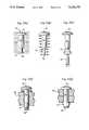
- FIGS. 4a through 4fsimplified cross-sectional views of an alternative embodiment of the present invention in which a fastener is formed by inserting a shank of shape memory alloy in an aluminum sleeve.
- FIGS. 5a through 5eare simplified cross-sectional views of yet another alternative embodiment in which a shank of shape memory alloy is used with a partial aluminum sleeve to form a fastener.
- Shape memory alloyshave the characteristic of retaining a memory of a previously "trained" shape.
- the alloycan be deformed, but will return to the trained shape when heated above a critical transformation temperature, T c . This is accomplished by a thermally-activated, reversible martensitic-austenitic phase transformation in the crystalline structure of the alloy.
- shape memory alloysare typically used in the following manner:
- a part (e.g., a wire) made of the shape memory alloyis formed by conventional means (e.g., a jig) into the desired trained shape.
- the partcan then be deformed by conventional means into a second, "deformed” shape while maintaining the temperature below the critical transformation temperature. A significant amount of deformation can be accommodated, often reaching in excess of 8%. This results in a deformed martensitic structure for the alloy.
- the partis then heated to a temperature above the critical transformation temperature by a heater or by ambient conditions. This causes the alloy to return to an austenitic crystalline structure, and to return from the deformed shape to an approximation of the trained shape.
- shape memory alloysare commercially available, including Raychem K-alloy (Ti-Ni-Cu) and nitinol (Ni-Ti).
- Other shape memory alloyssuch as copper-aluminum-nickel, copper-zinc-aluminum, and titanium-cobalt-nickel, are also known in the art.
- an alloysuch as iron-doped or chromium-doped Ni-Ti can be employed.
- the fastener 10is formed from a unitary piece of shape memory alloy having a head 12, an elongated shank 14, and an annular segment 16.
- the fastenerhas a deformed shape with substantially cylindrical shank 14 and annular segment 16. In this state, the cross-sectional dimensions of the shank 14 and annular segment 16 are sufficiently small to permit the shank 14 and annular segment 16 of the fastener 10 to be inserted into the opening extending through the adjacent workpieces 30 to be fastened together, as shown in FIG. 3(a).
- the head 12 of the fastener 10provides a predetermined maximum depth of insertion of the fastener 10 in the opening.
- the trained shape of the fasteneris shown in FIGS. 1(b) and 3(b).
- T ccritical transformation temperature
- this heatingcan be accomplished simply by allowing the fastener to warm to ambient conditions. This causes the annular segment 16 to flare radially outward toward a frusto-conical shape with dimensions at least as large, and preferably larger than the opening in the workpieces 30, as shown in FIG. 3(b), thereby securing the fastener 10 in the opening.
- FIGS. 2(a) through (c)show one possible method of fabricating and training the fastener using a jig.
- a blank for the fastener 10is first formed by conventional molding, forging, or machining techniques.
- the shank 14 of the fastener 10initially has a substantially cylindrical shape to simplify initial fabrication.
- the annular segment 16 at the lower end of the shankalso has a cylindrical void extending axially upward from its lower end toward the head 12 of the fastener 10.
- the fastener 10is positioned in the jig 20 as shown in cross-section in FIG. 2(a).
- a screw assemblyadvances a conical training die 22 in the jig 20 toward the lower end of the fastener 10, as shown in FIG.
- FIG. 2(b)which deforms the annular segment into a substantially frusto-conical shape, as shown in FIG. 2(b), which is preferably larger than the corresponding shape of the workpiece opening (compare FIGS. 2(b) and 3(b)).
- the jig 20is subjected to an annealing process in which the fastener 10 is heated to a temperature above the critical transformation temperature, T c , for the shape memory alloy. This elevated temperature results in an austenitic crystalline structure for the alloy. The jig is then cooled to a temperature below the critical transformation temperature, causing a martensitic transformation in the crystalline structure.
- the training die 22is removed after the annealing process is complete, and replaced with a knock-out die 24.
- the knock-out die 24forces the fastener 10 out through the hole in the left end of the jig 20.
- the annular segment 16undergoes plastic deformation from its frusto-conical trained shape into a substantially cylindrical shape.
- the temperatureremains below the critical transformation temperature, thereby resulting in a deformed martensitic crystalline structure for the fastener.
- the resulting fastener 10can be transported and/or stored for an indefinite period of time provide its temperature never exceeds the critical transformation temperature for the shape memory alloy.
- FIGS. 3(a) and 3(b)demonstrate installation of the fastener 10 in the workpieces 30.
- the fasteneris manually inserted in a preformed opening of appropriate dimensions extending through the workpieces, and then heated by means of a conventional heater 35 (or by ambient conditions for alloys with cyrogenic transformation temperatures) to a temperature above the critical transformation temperature.
- Thiscauses the fastener 10 to revert from its deformed martensitic state to an austenitic crystalline state, and causes the annular segment 16 to flare radially outward from its deformed cylindrical shape to an approximation of its frusto-conical trained shape (i.e. the trained shape).
- the dimensions and shape of the opening through the workpieces 30preferably correspond to the deformed and trained shapes of the fastener 10.
- the cross-sectional dimensions of the annular segment 16 and shank 14 of the fastener 10 in its deformed shapemust be sufficiently small to permit insertion into the opening in the workpieces.
- the head 12 of the fastener 10is typically large enough to provide a predetermined maximum limit for insertion of the fastener 10 into the opening.
- the trained shape of the annular segment 16must be sufficiently large to effectively lock the fastener 10 in place with respect to the workpieces 30. This is typically accomplished by using a shank that is long enough to cause the annular segment 16 to extend substantially through the opening to the opposite side of the workpieces 30.
- the sides of the openingcan be tapered radially outward as shown in FIGS. 3(a) and 3(b) to match the contour of the trained shape of the annular segment 16.
- the shank 14 of the fastener 10can also be trained, in addition to the annular segment 16.
- the shank 14can be trained to provide axial contraction and/or radial expansion by means of the training process outlined above. Radial expansion of the shank 14 can be used to seal the opening in the workpieces 30, and axial contraction is beneficial in ensuring compressive loading of the workpieces 30 between the head 12 and annular segment 16 of the fastener 10.
- FIGS. 4(a) through 4(f)show an alternative embodiment of the present invention in which a sleeve 45, made of a material such as aluminum, is added to enhance the deformational characteristics of a fastener core 40 made of a shape memory alloy. Axial contraction of the fastener core results in deformation of the lower end of the sleeve 41 into a frusto-conical shape to deploy the fastener.
- the fastener core 40is formed by conventional means into a trained shape having an upper head 42, a central elongated shank 44, and a lower annular segment 46.
- both the upper head 42 and lower annual segment 46can be simultaneously formed by the action of an opposing set of dies with conical faces.
- the fastener core 40is then heated to a temperature well above the critical transformation temperature for the shape memory alloy by a heater or by ambient conditions, thereby causing an austenitic transformation in the fastener core 40.
- the fastener coreis then cooled below the critical transformation temperature and the upper head 42 and lower annual segment 46 are deformed to smaller cross-sectional dimensions as shown in FIG. 4(b).
- the shank 44is also typically lengthened and reduced in diameter by rolling or pulling.
- the fastener core 40is inserted into a sleeve 45 having a head 43 and tubular shank 47.
- FIGS. 4(e) and 4(f)demonstrate the manner in which the fastener assembly is deployed in a hole or opening extending through the workpieces 30. The fastener assembly is manually inserted into the opening which preferably is slightly larger than the diameter of the fastener.
- the length of the fastener(between the head 43 of the sleeve 45 and the top of the lower annular segment 46 of the fastener core 40) preferably is slightly larger than the depth of the hole through the workpieces 30.
- the fastener assemblyis heated above the critical transformation temperature by a heater or by ambient conditions. This causes the fastener core to return to an approximation of the trained shape shown in FIG. 4(a).
- Radial expansion and axial contraction of the fastener core 40causes deformation of the sleeve 45, as shown in FIG. 4(f), substantially filling the opening and placing a compressive loading on the workpieces 30.
- FIGS. 5(a) through 5(e)disclose yet another alternative embodiment of the present invention using only a partial sleeve 51.
- the fastener 50is formed of a shaped memory alloy, as generally discussed above.
- the trained shape of the fastener 50includes a reduced segment 56 at the bottom of the shank 54 with a smaller diameter than the shank 54.
- the trained shapealso includes a frusto-conical retaining segment 58 at the bottom of the reduced segment 56.
- the fastener 50is annealed as shown in FIG. 5(a) and allowed to cool below the critical transformation temperature.
- the shank 54, reduced segment 56, and retaining segment 58are deformed (e.g., by rolling) to lengthen their axial dimensions and reduce their radial dimensions as shown in FIG. 5(b).
- the cross-section of the retaining segment 58is reduced sufficiently to permit the annular sleeve or collar 51 to be insert over the retaining segment 58 and onto the reduced segment 56 as shown in FIG. 5(c).
- a die 49is employed to deform the retaining segment 58 to hold the sleeve 51 in place on the reduced segment 56.
- FIGS. 5(d) and 5(e)demonstrate the manner in which the fastener is deployed in a hole or opening extending through the workpieces 30.
- the fasteneris manually inserted into the opening which preferably is slightly larger than the diameter of the fastener.
- the length of the fastener shank 54 in its deformed statepreferably is approximately equal to the depth of the hole through the workpieces 30.
- the fastener assemblyis heated above the critical transformation temperature by a heater or by ambient conditions. This causes the fastener to return to an approximation of the trained shape shown in FIG. 5(a).
- Axial contraction of the shank 54, coupled with radial expansion and axial contraction of the reduced segment 56 and retaining segment 58cause deformation of the sleeve 51, as shown in FIG. 5(e). This also causes compressive loading on the workpieces 30. Additionally, radial expansion of the shank 54 substantially fills the opening in the workpieces 30.
Landscapes
- Engineering & Computer Science (AREA)
- General Engineering & Computer Science (AREA)
- Mechanical Engineering (AREA)
- Insertion Pins And Rivets (AREA)
Abstract
Description
______________________________________ Inventor Patent No. Issue Date ______________________________________ Wolfe 2,994,933 Aug. 8, 1961 Otte, et al. 3,740,839 June 26, 1973 Thellmann 3,762,266 Oct. 2, 1973 Gapp, et al. 3,848,389 Nov. 19, 1974 Krumme 4,485,816 Dec. 4, 1984 Jackson, et al. 4,512,699 Apr. 23, 1985 Ignasiak 4,841,100 June 20, 1989 ______________________________________
Claims (30)
Priority Applications (1)
| Application Number | Priority Date | Filing Date | Title |
|---|---|---|---|
| US07/730,222US5120175A (en) | 1991-07-15 | 1991-07-15 | Shape memory alloy fastener |
Applications Claiming Priority (1)
| Application Number | Priority Date | Filing Date | Title |
|---|---|---|---|
| US07/730,222US5120175A (en) | 1991-07-15 | 1991-07-15 | Shape memory alloy fastener |
Publications (1)
| Publication Number | Publication Date |
|---|---|
| US5120175Atrue US5120175A (en) | 1992-06-09 |
Family
ID=24934456
Family Applications (1)
| Application Number | Title | Priority Date | Filing Date |
|---|---|---|---|
| US07/730,222Expired - LifetimeUS5120175A (en) | 1991-07-15 | 1991-07-15 | Shape memory alloy fastener |
Country Status (1)
| Country | Link |
|---|---|
| US (1) | US5120175A (en) |
Cited By (124)
| Publication number | Priority date | Publication date | Assignee | Title |
|---|---|---|---|---|
| US5254837A (en)* | 1991-07-15 | 1993-10-19 | The United States Of America As Represented By The Administrator Of The National Aeronautics And Space Administration | Thermally activated retainer means utilizing shape memory alloy |
| US5265456A (en)* | 1992-06-29 | 1993-11-30 | Grumman Aerospace Corporation | Method of cold working holes using a shape memory alloy tool |
| US5267832A (en)* | 1992-03-30 | 1993-12-07 | United Technologies Corporation | Flarable retainer |
| US5380221A (en)* | 1993-06-18 | 1995-01-10 | The Whitaker Corporation | Anchor pin |
| US5407322A (en)* | 1992-09-30 | 1995-04-18 | Societe Nationale D'etude Et De Construction De Moteurs D'aviation "Snecma" | Variable phase vane |
| US5414922A (en)* | 1992-09-21 | 1995-05-16 | Pm Hochtemperatur-Metall Gmbh | Process for producing a riveted joint by forming a rivet head onto a heated rivet pin using a riveting tool |
| US5536917A (en)* | 1994-06-23 | 1996-07-16 | Motorla, Inc. | Housing with integral thin film resistive snap-fits |
| WO1998020801A1 (en)* | 1995-07-18 | 1998-05-22 | Beth Israel Deaconess Medical Center | In vivo method for repairing a ruptured segment of a therapeutic appliance |
| US5858020A (en)* | 1995-12-05 | 1999-01-12 | Metagen, Llc | Modular prosthesis |
| US6080161A (en)* | 1999-03-19 | 2000-06-27 | Eaves, Iii; Felmont F. | Fastener and method for bone fixation |
| US6086305A (en)* | 1999-01-13 | 2000-07-11 | Illinois Tool Works Inc. | Nails having selected heat treatment and hardening |
| US6109851A (en)* | 1999-01-13 | 2000-08-29 | Illinois Tool Works Inc. | Screws having selected heat treatment and hardening |
| WO2001046597A1 (en)* | 1999-12-22 | 2001-06-28 | Brunel University | Releasable fasteners |
| US6257593B1 (en) | 1999-05-14 | 2001-07-10 | Patrick Michel White | Stress induced interposed connector |
| US6398450B1 (en) | 1998-08-20 | 2002-06-04 | British Aerospace Public Limited Company | Fastener arrangements |
| US6425829B1 (en)* | 1994-12-06 | 2002-07-30 | Nitinol Technologies, Inc. | Threaded load transferring attachment |
| US6436474B2 (en) | 1999-01-13 | 2002-08-20 | Illinois Tool Works Inc. | Method of chemically coating fasteners having improved penetration and withdrawal resistance |
| US6435519B1 (en) | 1999-05-14 | 2002-08-20 | Patrick Michel White | Stress-induced gasket |
| WO2002066844A1 (en)* | 2001-02-23 | 2002-08-29 | Siemens Aktiengesellschaft | Assembling element for connecting two objects, especially two device parts |
| US6464713B2 (en)* | 1990-06-28 | 2002-10-15 | Peter M. Bonutti | Body tissue fastening |
| US6499926B2 (en) | 2001-05-18 | 2002-12-31 | The Boeing Company | Fastener apparatus and method of fastening non-metallic structures |
| US6503579B1 (en)* | 1998-03-05 | 2003-01-07 | Nissin Electric Co., Ltd. | Plasma CVD method, plasma CVD apparatus, and electrode |
| WO2003037051A1 (en)* | 2001-10-19 | 2003-05-01 | Siemens Aktiengesellschaft | Object consisting of several individual parts, especially an electronic or electrotechnical device |
| US6564531B2 (en) | 1999-04-07 | 2003-05-20 | Dtl Technology Limited Partnership | Blow molded container with memory shrink closure attachment and method of making the same |
| US20030126828A1 (en)* | 2000-05-10 | 2003-07-10 | John Cook | Method of reinforcing structures |
| US6623487B1 (en)* | 2001-02-13 | 2003-09-23 | Biomet, Inc. | Temperature sensitive surgical fastener |
| US6637995B1 (en) | 2000-02-09 | 2003-10-28 | Patrick Michel White | Super-elastic rivet assembly |
| US20030225438A1 (en)* | 2000-03-13 | 2003-12-04 | Bonutti Peter M. | Method of using ultrasonic vibration to secure body tissue |
| US20030226249A1 (en)* | 2002-06-10 | 2003-12-11 | Schnabel John David | Riveting method |
| US20040003683A1 (en)* | 2000-07-06 | 2004-01-08 | Dickory Rudduck | Multi-function tool |
| WO2004010011A1 (en)* | 2002-07-22 | 2004-01-29 | Telezygology Inc | Fastener for assembly and disassembly |
| US6688828B1 (en)* | 2000-12-01 | 2004-02-10 | Arizona Board Of Regents | Self-torquing fasteners |
| US20040067122A1 (en)* | 2002-02-26 | 2004-04-08 | Arizona Board Of Regents | Self-torquing fasteners |
| GB2393927A (en)* | 2002-10-09 | 2004-04-14 | Bae Systems Plc | A method of assembling components |
| US20040173662A1 (en)* | 2002-08-07 | 2004-09-09 | Brent Christner | Welded joints with polymer sealant |
| US6797083B2 (en) | 2001-06-11 | 2004-09-28 | Ev3 Inc. | Method of training nitinol wire |
| US20040201152A1 (en)* | 2003-04-08 | 2004-10-14 | Honda Motor Co., Ltd. | Liquid sealed mount device |
| US20040220616A1 (en)* | 2000-03-13 | 2004-11-04 | Bonutti Peter M. | Method and device for securing body tissue |
| US20050172462A1 (en)* | 2002-06-19 | 2005-08-11 | Dickory Rudduck | Fixing and release systems and fastener networks |
| DE102004004658A1 (en)* | 2004-01-29 | 2005-09-15 | Faurecia Innenraum Systeme Gmbh | Fastening element with temperature-inducible deformation effect |
| US20050212304A1 (en)* | 2004-03-12 | 2005-09-29 | Herrera Guillermo A | Active seal assisted latching assemblies |
| US20050240190A1 (en)* | 2004-04-21 | 2005-10-27 | Gall Kenneth A | Osteosynthetic implants and methods of use and manufacture |
| US20060002787A1 (en)* | 2004-07-02 | 2006-01-05 | Siemens Westinghouse Power Corporation | Retraction retainer system for biased turbine engine components |
| CN1771399A (en)* | 2002-07-22 | 2006-05-10 | 远程接合技术公司 | Fasteners for assembly and disassembly |
| US7128753B1 (en) | 1990-06-28 | 2006-10-31 | Bonutti Peter M | Surgical devices having a polymeric material with a therapeutic agent and methods for making same |
| US7150680B2 (en) | 1999-05-14 | 2006-12-19 | Precimed S.A. | Drive shaft coupling |
| DE102005046567A1 (en)* | 2005-09-28 | 2007-03-29 | Burg Giebichenstein Hochschule für Kunst und Design | Elastomer rivet for connecting components, has shaft arranged before movement of elastomer having diameter greater than riveted hole, and fixed seat provided after elastomer movement by elasticity of riveted material between shaft and hole |
| US20070071575A1 (en)* | 2003-11-17 | 2007-03-29 | Dickory Rudduck | Fasteners and other assemblies |
| US20070095442A1 (en)* | 2005-10-28 | 2007-05-03 | Daniel Clark | Method for joining components |
| US7217059B1 (en) | 1998-03-18 | 2007-05-15 | Telezygology Pty Limited | Fixing and release systems |
| US20070270833A1 (en)* | 2006-02-07 | 2007-11-22 | Bonutti Peter M | Methods and devices for trauma welding |
| WO2008116203A2 (en) | 2007-03-22 | 2008-09-25 | Marctec, Llc | Methods and devices for intracorporeal bonding or interlocking of implants with thermal energy |
| US20080253830A1 (en)* | 2004-03-31 | 2008-10-16 | Akio Katsuki | Method of Installing Anchor Bolt, Method of Drilling Anchor Bolt Hole, and Drilling Device |
| US20080262629A1 (en)* | 2007-03-26 | 2008-10-23 | Fonte Matthew V | Proximally Self-Locking Long Bone Prosthesis |
| US20090041085A1 (en)* | 2001-03-23 | 2009-02-12 | Petrakis Dennis N | Temperature responsive systems |
| WO2009029908A1 (en) | 2007-08-30 | 2009-03-05 | Marctec, Llc | Methods and devices for utilizing thermal energy to bond, stake and/or remove implants |
| US20090119860A1 (en)* | 2006-03-16 | 2009-05-14 | Klaus Amsel | Riveted joint based on plastic |
| US20090190868A1 (en)* | 2008-01-30 | 2009-07-30 | Kane Daniel J | Memory shape bushings and bearings |
| US20100061795A1 (en)* | 2007-03-05 | 2010-03-11 | Renault S.A.S. | Arrangement for securing a gearshift lever trim base to the periphery of a surrounding covering |
| US20100155998A1 (en)* | 2008-12-19 | 2010-06-24 | 3M Innovative Properties Company | Shape memory polymer |
| US20100154181A1 (en)* | 2008-12-23 | 2010-06-24 | Ford Global Technologies Llc | Shape Memory Fastener |
| US20100202855A1 (en)* | 2009-02-10 | 2010-08-12 | Rolls-Royce Plc | Assembly |
| US20100293775A1 (en)* | 2006-09-12 | 2010-11-25 | Gm Global Technology Operations, Inc. | Reversible attachment mechanisms |
| US7854750B2 (en) | 2002-08-27 | 2010-12-21 | P Tech, Llc. | Apparatus and method for securing a suture |
| US7879072B2 (en) | 1997-08-01 | 2011-02-01 | P Tech, Llc. | Method for implanting a flowable fastener |
| US20110027093A1 (en)* | 2009-07-28 | 2011-02-03 | Snecma | Anti-wear device of a turbomachine rotor |
| US20110087277A1 (en)* | 2009-10-08 | 2011-04-14 | Tyco Healthcare Group Lp | Shape Memory Fasteners And Method Of Use |
| US20110135418A1 (en)* | 2009-12-07 | 2011-06-09 | Kirkwood Brad L | Self expanding fastener |
| US20110175295A1 (en)* | 2008-07-16 | 2011-07-21 | Karl Lenhardt | Linear Connector for Spacers in Insulating Glass Panes, Method for the Production Thereof and Method for Connecting Two Ends of a Hollow Profile Bar for a Spacer Using such a Linear Connector |
| US7996975B1 (en)* | 2004-09-30 | 2011-08-16 | Denslow Clark A | Method of making unified head for a staked fastener |
| US20110202042A1 (en)* | 2010-02-17 | 2011-08-18 | Roy Junius Rusly | Apparatus and methods for programming a shape-memory medical device implant |
| US8066778B2 (en) | 2005-04-21 | 2011-11-29 | Biomet Manufacturing Corp. | Porous metal cup with cobalt bearing surface |
| US20110299915A1 (en)* | 2009-09-15 | 2011-12-08 | William Mike Crane | Micro-coupling active release mechanism |
| US20110297732A1 (en)* | 2006-05-17 | 2011-12-08 | Warsaw Orthopedic, Inc. | Surgical Staple Assembly |
| US20120024932A1 (en)* | 2010-07-27 | 2012-02-02 | Rolls-Royce Plc | Tool |
| US8123814B2 (en) | 2001-02-23 | 2012-02-28 | Biomet Manufacturing Corp. | Method and appartus for acetabular reconstruction |
| US8197550B2 (en) | 2005-04-21 | 2012-06-12 | Biomet Manufacturing Corp. | Method and apparatus for use of porous implants |
| US20120181294A1 (en)* | 2005-12-15 | 2012-07-19 | Cornerstone Research Group, Inc. | Venting mechanism for containers |
| US8266780B2 (en)* | 2005-04-21 | 2012-09-18 | Biomet Manufacturing Corp. | Method and apparatus for use of porous implants |
| CN102996582A (en)* | 2012-03-30 | 2013-03-27 | 合肥工业大学 | Active dismounting structure and dismounting method of active dismounting structure |
| US8496657B2 (en) | 2006-02-07 | 2013-07-30 | P Tech, Llc. | Methods for utilizing vibratory energy to weld, stake and/or remove implants |
| US20130212856A1 (en)* | 2010-06-22 | 2013-08-22 | The Swatch Group Research And Development Ltd. | Method of assembling a part |
| US8617185B2 (en) | 2007-02-13 | 2013-12-31 | P Tech, Llc. | Fixation device |
| US20140214037A1 (en)* | 2011-07-18 | 2014-07-31 | Woodwelding Ag | Method and implant for stabilizing separated bone portions relative to each other |
| US8808329B2 (en) | 1998-02-06 | 2014-08-19 | Bonutti Skeletal Innovations Llc | Apparatus and method for securing a portion of a body |
| US8814902B2 (en) | 2000-05-03 | 2014-08-26 | Bonutti Skeletal Innovations Llc | Method of securing body tissue |
| US20140248011A1 (en)* | 2011-10-03 | 2014-09-04 | Bell Helicopter Textron Inc. | Bearing with a shape memory alloy component |
| US8845699B2 (en) | 1999-08-09 | 2014-09-30 | Bonutti Skeletal Innovations Llc | Method of securing tissue |
| US8845687B2 (en) | 1996-08-19 | 2014-09-30 | Bonutti Skeletal Innovations Llc | Anchor for securing a suture |
| US20150130110A1 (en)* | 2013-11-14 | 2015-05-14 | GM Global Technology Operations LLC | Fit and finish methods |
| US9060767B2 (en) | 2003-04-30 | 2015-06-23 | P Tech, Llc | Tissue fastener and methods for using same |
| US9089323B2 (en) | 2005-02-22 | 2015-07-28 | P Tech, Llc | Device and method for securing body tissue |
| US9138222B2 (en) | 2000-03-13 | 2015-09-22 | P Tech, Llc | Method and device for securing body tissue |
| US20150265278A1 (en)* | 2014-03-19 | 2015-09-24 | Boston Scientific Scimed, Inc. | Closure devices, systems, and methods for treating body tissue |
| US9149281B2 (en) | 2002-03-20 | 2015-10-06 | P Tech, Llc | Robotic system for engaging a fastener with body tissue |
| US9173647B2 (en) | 2004-10-26 | 2015-11-03 | P Tech, Llc | Tissue fixation system |
| US9226828B2 (en) | 2004-10-26 | 2016-01-05 | P Tech, Llc | Devices and methods for stabilizing tissue and implants |
| US9271766B2 (en) | 2004-10-26 | 2016-03-01 | P Tech, Llc | Devices and methods for stabilizing tissue and implants |
| US20160169256A1 (en)* | 2011-06-09 | 2016-06-16 | United Technologies Corporation | Method and assembly for attaching components |
| WO2016115346A1 (en)* | 2015-01-14 | 2016-07-21 | Eaton Corporation | Engine valve lifter anti-rotation device |
| US9439642B2 (en) | 2006-02-07 | 2016-09-13 | P Tech, Llc | Methods and devices for utilizing bondable materials |
| US9463012B2 (en) | 2004-10-26 | 2016-10-11 | P Tech, Llc | Apparatus for guiding and positioning an implant |
| US9522022B2 (en) | 2013-11-18 | 2016-12-20 | Biomedical Enterprises, Inc. | Method and appparatus for an intramedullary implant and method of implantation therefor |
| US9636155B2 (en) | 2013-11-18 | 2017-05-02 | Biomedical Enterprises, Inc. | Method and apparatus for an intramudullary implant and method of implantation thereof |
| US9657762B2 (en) | 2015-03-12 | 2017-05-23 | Northrop Grumman Systems Corporation | Thermally activated, shape configurable mechanical locking Z-pin |
| US9770238B2 (en) | 2001-12-03 | 2017-09-26 | P Tech, Llc | Magnetic positioning apparatus |
| US9775659B2 (en) | 2010-10-04 | 2017-10-03 | Biomedical Enterprises, Inc. | Method and system for storing and inserting an implant |
| US20170292547A1 (en)* | 2014-07-03 | 2017-10-12 | The Boeing Company | Assemblies including shape memory alloy fittings and composite structural members |
| US9888916B2 (en) | 2004-03-09 | 2018-02-13 | P Tech, Llc | Method and device for securing body tissue |
| US9986668B2 (en) | 2008-01-03 | 2018-05-29 | Apple Inc. | Metal retaining features for handheld electronic device casing |
| JP2018119657A (en)* | 2017-01-27 | 2018-08-02 | 株式会社古河テクノマテリアル | Connection structure and manufacturing method of connection structure |
| US10058393B2 (en) | 2015-10-21 | 2018-08-28 | P Tech, Llc | Systems and methods for navigation and visualization |
| US10076377B2 (en) | 2013-01-05 | 2018-09-18 | P Tech, Llc | Fixation systems and methods |
| CN109613674A (en)* | 2018-12-24 | 2019-04-12 | 中北大学 | A laser light source collimation device using memory alloy structure |
| CN110947895A (en)* | 2019-11-20 | 2020-04-03 | 四川大学 | Automatic riveting device for shape memory alloy rivet |
| DE102018125807A1 (en)* | 2018-10-17 | 2020-04-23 | Technische Universität Darmstadt | Connection element and connection system with a connection element |
| US10669007B2 (en) | 2011-06-09 | 2020-06-02 | Raytheon Technologies Corporation | Method and apparatus for attaching components having dissimilar rates of thermal expansion |
| US10695985B2 (en) | 2015-09-10 | 2020-06-30 | Short Brothers Plc | Method for designing and fitting, via interference, an insert into an opening in a non-metallic material |
| US20200215765A1 (en)* | 2017-09-21 | 2020-07-09 | Continental Automotive Gmbh | Rivet connection and method for producing a rivet connection |
| US11246638B2 (en) | 2006-05-03 | 2022-02-15 | P Tech, Llc | Methods and devices for utilizing bondable materials |
| US11253296B2 (en) | 2006-02-07 | 2022-02-22 | P Tech, Llc | Methods and devices for intracorporeal bonding of implants with thermal energy |
| US11278331B2 (en) | 2006-02-07 | 2022-03-22 | P Tech Llc | Method and devices for intracorporeal bonding of implants with thermal energy |
| US20230053525A1 (en)* | 2013-06-14 | 2023-02-23 | James Alan Monroe | Thermally stabilized fastener system and method |
| US12064156B2 (en) | 2023-01-09 | 2024-08-20 | John F. Krumme | Dynamic compression fixation devices |
Citations (13)
| Publication number | Priority date | Publication date | Assignee | Title |
|---|---|---|---|---|
| US980420A (en)* | 1907-03-14 | 1911-01-03 | Mcmeen & Miller | Bimetallic rivet. |
| US1947906A (en)* | 1933-06-23 | 1934-02-20 | William H Fine | Rivet fastener |
| US2080220A (en)* | 1935-05-25 | 1937-05-11 | Butter Karl | Explosion rivet |
| US2994933A (en)* | 1956-04-04 | 1961-08-08 | Sheemon A Wolfe | Grommet |
| US3740839A (en)* | 1971-06-29 | 1973-06-26 | Raychem Corp | Cryogenic connection method and means |
| US3762266A (en)* | 1970-11-09 | 1973-10-02 | Gould Inc | Bimetal fastener |
| US3848389A (en)* | 1969-12-29 | 1974-11-19 | Textron Inc | Bimetal rivets |
| SU777270A1 (en)* | 1979-01-08 | 1980-11-07 | за витель Н. Н. Рахманов | Part non-releasable connection |
| US4485816A (en)* | 1981-06-25 | 1984-12-04 | Alchemia | Shape-memory surgical staple apparatus and method for use in surgical suturing |
| US4512699A (en)* | 1983-05-17 | 1985-04-23 | The United States Of America As Represented By The Administrator Of The National Aeronautics And Space Administration | Daze fasteners |
| US4754538A (en)* | 1983-11-15 | 1988-07-05 | Raychem Corporation | Annular tube-like driver |
| US4841100A (en)* | 1987-09-02 | 1989-06-20 | Minnesota Mining And Manufacturing Company | Expanding surface mount compatible retainer post |
| US4985979A (en)* | 1989-01-23 | 1991-01-22 | Mcdonnell Douglas Corporation | Method of installing interference fit sleeved fasteners having radiused intersection for stress coining |
- 1991
- 1991-07-15USUS07/730,222patent/US5120175A/ennot_activeExpired - Lifetime
Patent Citations (13)
| Publication number | Priority date | Publication date | Assignee | Title |
|---|---|---|---|---|
| US980420A (en)* | 1907-03-14 | 1911-01-03 | Mcmeen & Miller | Bimetallic rivet. |
| US1947906A (en)* | 1933-06-23 | 1934-02-20 | William H Fine | Rivet fastener |
| US2080220A (en)* | 1935-05-25 | 1937-05-11 | Butter Karl | Explosion rivet |
| US2994933A (en)* | 1956-04-04 | 1961-08-08 | Sheemon A Wolfe | Grommet |
| US3848389A (en)* | 1969-12-29 | 1974-11-19 | Textron Inc | Bimetal rivets |
| US3762266A (en)* | 1970-11-09 | 1973-10-02 | Gould Inc | Bimetal fastener |
| US3740839A (en)* | 1971-06-29 | 1973-06-26 | Raychem Corp | Cryogenic connection method and means |
| SU777270A1 (en)* | 1979-01-08 | 1980-11-07 | за витель Н. Н. Рахманов | Part non-releasable connection |
| US4485816A (en)* | 1981-06-25 | 1984-12-04 | Alchemia | Shape-memory surgical staple apparatus and method for use in surgical suturing |
| US4512699A (en)* | 1983-05-17 | 1985-04-23 | The United States Of America As Represented By The Administrator Of The National Aeronautics And Space Administration | Daze fasteners |
| US4754538A (en)* | 1983-11-15 | 1988-07-05 | Raychem Corporation | Annular tube-like driver |
| US4841100A (en)* | 1987-09-02 | 1989-06-20 | Minnesota Mining And Manufacturing Company | Expanding surface mount compatible retainer post |
| US4985979A (en)* | 1989-01-23 | 1991-01-22 | Mcdonnell Douglas Corporation | Method of installing interference fit sleeved fasteners having radiused intersection for stress coining |
Cited By (258)
| Publication number | Priority date | Publication date | Assignee | Title |
|---|---|---|---|---|
| US7208013B1 (en) | 1990-06-28 | 2007-04-24 | Bonutti Ip, Llc | Composite surgical devices |
| US6464713B2 (en)* | 1990-06-28 | 2002-10-15 | Peter M. Bonutti | Body tissue fastening |
| US7217290B2 (en) | 1990-06-28 | 2007-05-15 | Bonutti Peter M | Surgical devices containing a heat bondable material with a therapeutic agent |
| US20030069605A1 (en)* | 1990-06-28 | 2003-04-10 | Bonutti Peter M. | Surgical devices containing a heat bondable material with a therapeutic agent |
| US7128753B1 (en) | 1990-06-28 | 2006-10-31 | Bonutti Peter M | Surgical devices having a polymeric material with a therapeutic agent and methods for making same |
| US5254837A (en)* | 1991-07-15 | 1993-10-19 | The United States Of America As Represented By The Administrator Of The National Aeronautics And Space Administration | Thermally activated retainer means utilizing shape memory alloy |
| US5267832A (en)* | 1992-03-30 | 1993-12-07 | United Technologies Corporation | Flarable retainer |
| US5265456A (en)* | 1992-06-29 | 1993-11-30 | Grumman Aerospace Corporation | Method of cold working holes using a shape memory alloy tool |
| US5414922A (en)* | 1992-09-21 | 1995-05-16 | Pm Hochtemperatur-Metall Gmbh | Process for producing a riveted joint by forming a rivet head onto a heated rivet pin using a riveting tool |
| US5407322A (en)* | 1992-09-30 | 1995-04-18 | Societe Nationale D'etude Et De Construction De Moteurs D'aviation "Snecma" | Variable phase vane |
| US5380221A (en)* | 1993-06-18 | 1995-01-10 | The Whitaker Corporation | Anchor pin |
| EP0630072A3 (en)* | 1993-06-18 | 1996-02-21 | Whitaker Corp | Anchor pin. |
| US5536917A (en)* | 1994-06-23 | 1996-07-16 | Motorla, Inc. | Housing with integral thin film resistive snap-fits |
| US6425829B1 (en)* | 1994-12-06 | 2002-07-30 | Nitinol Technologies, Inc. | Threaded load transferring attachment |
| WO1998020801A1 (en)* | 1995-07-18 | 1998-05-22 | Beth Israel Deaconess Medical Center | In vivo method for repairing a ruptured segment of a therapeutic appliance |
| US5858020A (en)* | 1995-12-05 | 1999-01-12 | Metagen, Llc | Modular prosthesis |
| US8845687B2 (en) | 1996-08-19 | 2014-09-30 | Bonutti Skeletal Innovations Llc | Anchor for securing a suture |
| US7879072B2 (en) | 1997-08-01 | 2011-02-01 | P Tech, Llc. | Method for implanting a flowable fastener |
| US8808329B2 (en) | 1998-02-06 | 2014-08-19 | Bonutti Skeletal Innovations Llc | Apparatus and method for securing a portion of a body |
| US6503579B1 (en)* | 1998-03-05 | 2003-01-07 | Nissin Electric Co., Ltd. | Plasma CVD method, plasma CVD apparatus, and electrode |
| US7217059B1 (en) | 1998-03-18 | 2007-05-15 | Telezygology Pty Limited | Fixing and release systems |
| US6646240B2 (en) | 1998-08-20 | 2003-11-11 | British Aerospace Public Limited Company | Fastening arrangements |
| US6398450B1 (en) | 1998-08-20 | 2002-06-04 | British Aerospace Public Limited Company | Fastener arrangements |
| US6086305A (en)* | 1999-01-13 | 2000-07-11 | Illinois Tool Works Inc. | Nails having selected heat treatment and hardening |
| US6109851A (en)* | 1999-01-13 | 2000-08-29 | Illinois Tool Works Inc. | Screws having selected heat treatment and hardening |
| US6364972B1 (en) | 1999-01-13 | 2002-04-02 | Illinois Tool Works Inc. | Method for selectively hardening a carbon steel screw |
| US6273974B1 (en) | 1999-01-13 | 2001-08-14 | Illinois Tool Works Inc. | Selected heat treatment and hardening method for nails |
| US6436474B2 (en) | 1999-01-13 | 2002-08-20 | Illinois Tool Works Inc. | Method of chemically coating fasteners having improved penetration and withdrawal resistance |
| WO2000056236A1 (en) | 1999-03-19 | 2000-09-28 | Eaves Felmont F Iii | Fastener and method for bone fixation |
| US6080161A (en)* | 1999-03-19 | 2000-06-27 | Eaves, Iii; Felmont F. | Fastener and method for bone fixation |
| US6564531B2 (en) | 1999-04-07 | 2003-05-20 | Dtl Technology Limited Partnership | Blow molded container with memory shrink closure attachment and method of making the same |
| US6435519B1 (en) | 1999-05-14 | 2002-08-20 | Patrick Michel White | Stress-induced gasket |
| US7150680B2 (en) | 1999-05-14 | 2006-12-19 | Precimed S.A. | Drive shaft coupling |
| US6257593B1 (en) | 1999-05-14 | 2001-07-10 | Patrick Michel White | Stress induced interposed connector |
| US8845699B2 (en) | 1999-08-09 | 2014-09-30 | Bonutti Skeletal Innovations Llc | Method of securing tissue |
| WO2001046597A1 (en)* | 1999-12-22 | 2001-06-28 | Brunel University | Releasable fasteners |
| US6637995B1 (en) | 2000-02-09 | 2003-10-28 | Patrick Michel White | Super-elastic rivet assembly |
| US9067362B2 (en) | 2000-03-13 | 2015-06-30 | P Tech, Llc | Method of using ultrasonic vibration to secure body tissue with fastening element |
| US20030225438A1 (en)* | 2000-03-13 | 2003-12-04 | Bonutti Peter M. | Method of using ultrasonic vibration to secure body tissue |
| US20060235470A1 (en)* | 2000-03-13 | 2006-10-19 | Bonutti Peter M | Method of using ultrasonic vibration to secure implantable member to body tissue |
| US9884451B2 (en) | 2000-03-13 | 2018-02-06 | P Tech, Llc | Method of using ultrasonic vibration to secure body tissue |
| US7429266B2 (en) | 2000-03-13 | 2008-09-30 | Marctec, Llc | Method of using ultrasonic vibration to secure body tissue |
| US8747439B2 (en) | 2000-03-13 | 2014-06-10 | P Tech, Llc | Method of using ultrasonic vibration to secure body tissue with fastening element |
| US20060241695A1 (en)* | 2000-03-13 | 2006-10-26 | Bonutti Peter M | Method of using ultrasonic vibration to secure body tissue with fastening element |
| US8932330B2 (en) | 2000-03-13 | 2015-01-13 | P Tech, Llc | Method and device for securing body tissue |
| US20040220616A1 (en)* | 2000-03-13 | 2004-11-04 | Bonutti Peter M. | Method and device for securing body tissue |
| US9138222B2 (en) | 2000-03-13 | 2015-09-22 | P Tech, Llc | Method and device for securing body tissue |
| US9986994B2 (en) | 2000-03-13 | 2018-06-05 | P Tech, Llc | Method and device for securing body tissue |
| US8814902B2 (en) | 2000-05-03 | 2014-08-26 | Bonutti Skeletal Innovations Llc | Method of securing body tissue |
| US20030126828A1 (en)* | 2000-05-10 | 2003-07-10 | John Cook | Method of reinforcing structures |
| US6865791B2 (en)* | 2000-05-10 | 2005-03-15 | Qinetiq Limited | Method of generating force between a structure and an additional member |
| US20040003683A1 (en)* | 2000-07-06 | 2004-01-08 | Dickory Rudduck | Multi-function tool |
| US8166836B2 (en) | 2000-07-06 | 2012-05-01 | Telezygology, Inc. | Multi-function tool |
| US6688828B1 (en)* | 2000-12-01 | 2004-02-10 | Arizona Board Of Regents | Self-torquing fasteners |
| US6623487B1 (en)* | 2001-02-13 | 2003-09-23 | Biomet, Inc. | Temperature sensitive surgical fastener |
| DE10108956A1 (en)* | 2001-02-23 | 2002-09-12 | Siemens Ag | Mounting element for connecting two objects, in particular two parts of the device |
| US9375316B2 (en) | 2001-02-23 | 2016-06-28 | Biomet Manufacturing, Llc. | Method and apparatus for acetabular reconstruction |
| US8123814B2 (en) | 2001-02-23 | 2012-02-28 | Biomet Manufacturing Corp. | Method and appartus for acetabular reconstruction |
| US8551181B2 (en) | 2001-02-23 | 2013-10-08 | Biomet Manufacturing, Llc | Method and apparatus for acetabular reconstruction |
| WO2002066844A1 (en)* | 2001-02-23 | 2002-08-29 | Siemens Aktiengesellschaft | Assembling element for connecting two objects, especially two device parts |
| US8172458B2 (en)* | 2001-03-23 | 2012-05-08 | Petrakis Dennis N | Temperature responsive systems |
| US20090041085A1 (en)* | 2001-03-23 | 2009-02-12 | Petrakis Dennis N | Temperature responsive systems |
| US6499926B2 (en) | 2001-05-18 | 2002-12-31 | The Boeing Company | Fastener apparatus and method of fastening non-metallic structures |
| US7413622B2 (en) | 2001-06-11 | 2008-08-19 | Ev3 Inc. | Method of training nitinol wire |
| US6797083B2 (en) | 2001-06-11 | 2004-09-28 | Ev3 Inc. | Method of training nitinol wire |
| US20050061406A1 (en)* | 2001-06-11 | 2005-03-24 | Ev3 Inc. | Method of training nitinol wire |
| WO2003037051A1 (en)* | 2001-10-19 | 2003-05-01 | Siemens Aktiengesellschaft | Object consisting of several individual parts, especially an electronic or electrotechnical device |
| US9770238B2 (en) | 2001-12-03 | 2017-09-26 | P Tech, Llc | Magnetic positioning apparatus |
| US20040067122A1 (en)* | 2002-02-26 | 2004-04-08 | Arizona Board Of Regents | Self-torquing fasteners |
| US9808318B2 (en) | 2002-03-20 | 2017-11-07 | P Tech, Llc | Robotic arthroplasty system |
| US10932869B2 (en) | 2002-03-20 | 2021-03-02 | P Tech, Llc | Robotic surgery |
| US9486227B2 (en) | 2002-03-20 | 2016-11-08 | P Tech, Llc | Robotic retractor system |
| US10869728B2 (en) | 2002-03-20 | 2020-12-22 | P Tech, Llc | Robotic surgery |
| US10265128B2 (en) | 2002-03-20 | 2019-04-23 | P Tech, Llc | Methods of using a robotic spine system |
| US9629687B2 (en) | 2002-03-20 | 2017-04-25 | P Tech, Llc | Robotic arthroplasty system |
| US9149281B2 (en) | 2002-03-20 | 2015-10-06 | P Tech, Llc | Robotic system for engaging a fastener with body tissue |
| US9585725B2 (en) | 2002-03-20 | 2017-03-07 | P Tech, Llc | Robotic arthroplasty system |
| US10959791B2 (en) | 2002-03-20 | 2021-03-30 | P Tech, Llc | Robotic surgery |
| US9271741B2 (en) | 2002-03-20 | 2016-03-01 | P Tech, Llc | Robotic ultrasonic energy system |
| US9877793B2 (en) | 2002-03-20 | 2018-01-30 | P Tech, Llc | Robotic arthroplasty system |
| US9271779B2 (en) | 2002-03-20 | 2016-03-01 | P Tech, Llc | Methods of using a robotic spine system |
| US9192395B2 (en) | 2002-03-20 | 2015-11-24 | P Tech, Llc | Robotic fastening system |
| US10368953B2 (en) | 2002-03-20 | 2019-08-06 | P Tech, Llc | Robotic system for fastening layers of body tissue together and method thereof |
| US9155544B2 (en) | 2002-03-20 | 2015-10-13 | P Tech, Llc | Robotic systems and methods |
| US6877204B1 (en)* | 2002-06-10 | 2005-04-12 | Sun Microsystems, Inc. | Riveting method |
| US20030226249A1 (en)* | 2002-06-10 | 2003-12-11 | Schnabel John David | Riveting method |
| US6751841B2 (en)* | 2002-06-10 | 2004-06-22 | Sun Microsystems, Inc. | Riveting method |
| US7600301B2 (en) | 2002-06-19 | 2009-10-13 | Telezygology, Inc. | Fixing and release systems and fastener networks |
| US20050172462A1 (en)* | 2002-06-19 | 2005-08-11 | Dickory Rudduck | Fixing and release systems and fastener networks |
| US20060019510A1 (en)* | 2002-07-22 | 2006-01-26 | Telezygology, Inc. | Fastener for assembly and disassembly |
| WO2004010011A1 (en)* | 2002-07-22 | 2004-01-29 | Telezygology Inc | Fastener for assembly and disassembly |
| CN1771399A (en)* | 2002-07-22 | 2006-05-10 | 远程接合技术公司 | Fasteners for assembly and disassembly |
| JP2006515407A (en)* | 2002-07-22 | 2006-05-25 | テレズィゴロジー インク | Fasteners for assembly and disassembly |
| US7225966B2 (en) | 2002-08-07 | 2007-06-05 | Eclipse Aviation Corporation | Welded joints with polymer sealant |
| US20040173662A1 (en)* | 2002-08-07 | 2004-09-09 | Brent Christner | Welded joints with polymer sealant |
| US9750496B2 (en) | 2002-08-27 | 2017-09-05 | P Tech, Llc | System for securing a portion of a body |
| US7854750B2 (en) | 2002-08-27 | 2010-12-21 | P Tech, Llc. | Apparatus and method for securing a suture |
| US8162977B2 (en) | 2002-08-27 | 2012-04-24 | P Tech, Llc. | Method for joining implants |
| GB2393927A (en)* | 2002-10-09 | 2004-04-14 | Bae Systems Plc | A method of assembling components |
| US20040201152A1 (en)* | 2003-04-08 | 2004-10-14 | Honda Motor Co., Ltd. | Liquid sealed mount device |
| US7192013B2 (en)* | 2003-04-08 | 2007-03-20 | Honda Motor Co., Ltd. | Liquid sealed mount device |
| US9060767B2 (en) | 2003-04-30 | 2015-06-23 | P Tech, Llc | Tissue fastener and methods for using same |
| US9962162B2 (en) | 2003-04-30 | 2018-05-08 | P Tech, Llc | Tissue fastener and methods for using same |
| EP2302230A3 (en)* | 2003-11-17 | 2012-06-20 | Telezygology Inc. | Shape memory fastener assembly |
| US20100011548A1 (en)* | 2003-11-17 | 2010-01-21 | Dickory Rudduck | Fasteners and Other Assemblies |
| US20070071575A1 (en)* | 2003-11-17 | 2007-03-29 | Dickory Rudduck | Fasteners and other assemblies |
| US7610783B2 (en) | 2003-11-17 | 2009-11-03 | Telezygology Inc. | Fasteners and other assemblies |
| DE102004004658B4 (en)* | 2004-01-29 | 2006-01-12 | Faurecia Innenraum Systeme Gmbh | Fastening element with temperature-inducible deformation effect |
| DE102004004658A1 (en)* | 2004-01-29 | 2005-09-15 | Faurecia Innenraum Systeme Gmbh | Fastening element with temperature-inducible deformation effect |
| US9888916B2 (en) | 2004-03-09 | 2018-02-13 | P Tech, Llc | Method and device for securing body tissue |
| US20050212304A1 (en)* | 2004-03-12 | 2005-09-29 | Herrera Guillermo A | Active seal assisted latching assemblies |
| US20080253830A1 (en)* | 2004-03-31 | 2008-10-16 | Akio Katsuki | Method of Installing Anchor Bolt, Method of Drilling Anchor Bolt Hole, and Drilling Device |
| US8118952B2 (en) | 2004-04-21 | 2012-02-21 | Medshape Solutions, Inc. | Osteosynthetic implants and methods of use and manufacture |
| US20080269808A1 (en)* | 2004-04-21 | 2008-10-30 | Medshape Solutions, Inc | Osteosynthetic Implants and Methods of Use and Manufacture |
| US20050240190A1 (en)* | 2004-04-21 | 2005-10-27 | Gall Kenneth A | Osteosynthetic implants and methods of use and manufacture |
| US7985222B2 (en) | 2004-04-21 | 2011-07-26 | Medshape Solutions, Inc. | Osteosynthetic implants and methods of use and manufacture |
| US7121785B2 (en) | 2004-07-02 | 2006-10-17 | Siemens Power Generation, Inc. | Retraction retainer system for biased turbine engine components |
| US20060002787A1 (en)* | 2004-07-02 | 2006-01-05 | Siemens Westinghouse Power Corporation | Retraction retainer system for biased turbine engine components |
| US7996975B1 (en)* | 2004-09-30 | 2011-08-16 | Denslow Clark A | Method of making unified head for a staked fastener |
| US10813764B2 (en) | 2004-10-26 | 2020-10-27 | P Tech, Llc | Expandable introducer system and methods |
| US9579129B2 (en) | 2004-10-26 | 2017-02-28 | P Tech, Llc | Devices and methods for stabilizing tissue and implants |
| US9867706B2 (en) | 2004-10-26 | 2018-01-16 | P Tech, Llc | Tissue fastening system |
| US9271766B2 (en) | 2004-10-26 | 2016-03-01 | P Tech, Llc | Devices and methods for stabilizing tissue and implants |
| US9545268B2 (en) | 2004-10-26 | 2017-01-17 | P Tech, Llc | Devices and methods for stabilizing tissue and implants |
| US9226828B2 (en) | 2004-10-26 | 2016-01-05 | P Tech, Llc | Devices and methods for stabilizing tissue and implants |
| US9173647B2 (en) | 2004-10-26 | 2015-11-03 | P Tech, Llc | Tissue fixation system |
| US11992205B2 (en) | 2004-10-26 | 2024-05-28 | P Tech, Llc | Devices and methods for stabilizing tissue and implants |
| US9814453B2 (en) | 2004-10-26 | 2017-11-14 | P Tech, Llc | Deformable fastener system |
| US9999449B2 (en) | 2004-10-26 | 2018-06-19 | P Tech, Llc | Devices and methods for stabilizing tissue and implants |
| US9980761B2 (en) | 2004-10-26 | 2018-05-29 | P Tech, Llc | Tissue fixation system and method |
| US9463012B2 (en) | 2004-10-26 | 2016-10-11 | P Tech, Llc | Apparatus for guiding and positioning an implant |
| US10238378B2 (en) | 2004-10-26 | 2019-03-26 | P Tech, Llc | Tissue fixation system and method |
| US11013542B2 (en) | 2004-10-26 | 2021-05-25 | P Tech, Llc | Tissue fixation system and method |
| US11457958B2 (en) | 2004-10-26 | 2022-10-04 | P Tech, Llc | Devices and methods for stabilizing tissue and implants |
| US9980717B2 (en) | 2005-02-22 | 2018-05-29 | P Tech, Llc | Device and method for securing body tissue |
| US9089323B2 (en) | 2005-02-22 | 2015-07-28 | P Tech, Llc | Device and method for securing body tissue |
| WO2006116164A1 (en)* | 2005-04-21 | 2006-11-02 | Medshape Solutions, Inc. | Osteosynthetic implants and methods of use and manufacture |
| CN101208051B (en)* | 2005-04-21 | 2010-11-03 | 夏普医学解决方案公司 | Osteosynthetic implants and methods of use and manufacture |
| US8266780B2 (en)* | 2005-04-21 | 2012-09-18 | Biomet Manufacturing Corp. | Method and apparatus for use of porous implants |
| US8066778B2 (en) | 2005-04-21 | 2011-11-29 | Biomet Manufacturing Corp. | Porous metal cup with cobalt bearing surface |
| US8197550B2 (en) | 2005-04-21 | 2012-06-12 | Biomet Manufacturing Corp. | Method and apparatus for use of porous implants |
| DE102005046567A1 (en)* | 2005-09-28 | 2007-03-29 | Burg Giebichenstein Hochschule für Kunst und Design | Elastomer rivet for connecting components, has shaft arranged before movement of elastomer having diameter greater than riveted hole, and fixed seat provided after elastomer movement by elasticity of riveted material between shaft and hole |
| US10376259B2 (en) | 2005-10-05 | 2019-08-13 | P Tech, Llc | Deformable fastener system |
| US11219446B2 (en) | 2005-10-05 | 2022-01-11 | P Tech, Llc | Deformable fastener system |
| US10441269B1 (en) | 2005-10-05 | 2019-10-15 | P Tech, Llc | Deformable fastener system |
| US7841060B2 (en)* | 2005-10-28 | 2010-11-30 | Rolls-Royce Plc | Method for joining components |
| US20070095442A1 (en)* | 2005-10-28 | 2007-05-03 | Daniel Clark | Method for joining components |
| US20120181294A1 (en)* | 2005-12-15 | 2012-07-19 | Cornerstone Research Group, Inc. | Venting mechanism for containers |
| US8720722B2 (en)* | 2005-12-15 | 2014-05-13 | Cornerstone Research Group, Inc. | Venting mechanism for containers |
| US8496657B2 (en) | 2006-02-07 | 2013-07-30 | P Tech, Llc. | Methods for utilizing vibratory energy to weld, stake and/or remove implants |
| US9439642B2 (en) | 2006-02-07 | 2016-09-13 | P Tech, Llc | Methods and devices for utilizing bondable materials |
| US9743963B2 (en) | 2006-02-07 | 2017-08-29 | P Tech, Llc | Methods and devices for trauma welding |
| US7967820B2 (en)* | 2006-02-07 | 2011-06-28 | P Tech, Llc. | Methods and devices for trauma welding |
| US11129645B2 (en) | 2006-02-07 | 2021-09-28 | P Tech, Llc | Methods of securing a fastener |
| US11278331B2 (en) | 2006-02-07 | 2022-03-22 | P Tech Llc | Method and devices for intracorporeal bonding of implants with thermal energy |
| US9421005B2 (en) | 2006-02-07 | 2016-08-23 | P Tech, Llc | Methods and devices for intracorporeal bonding of implants with thermal energy |
| US11998251B2 (en) | 2006-02-07 | 2024-06-04 | P Tech, Llc | Methods and devices for intracorporeal bonding of implants with thermal energy |
| US10368924B2 (en) | 2006-02-07 | 2019-08-06 | P Tech, Llc | Methods and devices for trauma welding |
| US11253296B2 (en) | 2006-02-07 | 2022-02-22 | P Tech, Llc | Methods and devices for intracorporeal bonding of implants with thermal energy |
| US9610073B2 (en) | 2006-02-07 | 2017-04-04 | P Tech, Llc | Methods and devices for intracorporeal bonding of implants with thermal energy |
| US20070270833A1 (en)* | 2006-02-07 | 2007-11-22 | Bonutti Peter M | Methods and devices for trauma welding |
| US9173650B2 (en) | 2006-02-07 | 2015-11-03 | P Tech, Llc | Methods and devices for trauma welding |
| US11134995B2 (en) | 2006-02-07 | 2021-10-05 | P Tech, Llc | Method and devices for intracorporeal bonding of implants with thermal energy |
| US20090119860A1 (en)* | 2006-03-16 | 2009-05-14 | Klaus Amsel | Riveted joint based on plastic |
| US12232789B2 (en) | 2006-05-03 | 2025-02-25 | P Tech, Llc | Methods and devices for utilizing bondable materials |
| US11246638B2 (en) | 2006-05-03 | 2022-02-15 | P Tech, Llc | Methods and devices for utilizing bondable materials |
| US12402927B2 (en) | 2006-05-03 | 2025-09-02 | P Tech, Llc | Methods and devices for utilizing bondable materials |
| US20110297732A1 (en)* | 2006-05-17 | 2011-12-08 | Warsaw Orthopedic, Inc. | Surgical Staple Assembly |
| US20100293775A1 (en)* | 2006-09-12 | 2010-11-25 | Gm Global Technology Operations, Inc. | Reversible attachment mechanisms |
| US8096034B2 (en)* | 2006-09-12 | 2012-01-17 | GM Global Technology Operations LLC | Reversible attachment mechanisms process |
| US10390817B2 (en) | 2007-02-13 | 2019-08-27 | P Tech, Llc | Tissue fixation system and method |
| US10517584B1 (en) | 2007-02-13 | 2019-12-31 | P Tech, Llc | Tissue fixation system and method |
| US9402668B2 (en) | 2007-02-13 | 2016-08-02 | P Tech, Llc | Tissue fixation system and method |
| US8617185B2 (en) | 2007-02-13 | 2013-12-31 | P Tech, Llc. | Fixation device |
| US12137898B2 (en) | 2007-02-13 | 2024-11-12 | P Tech, Llc | Tissue fixation system and method |
| US11801044B2 (en) | 2007-02-13 | 2023-10-31 | P Tech, Llc | Tissue fixation system and method |
| US20100061795A1 (en)* | 2007-03-05 | 2010-03-11 | Renault S.A.S. | Arrangement for securing a gearshift lever trim base to the periphery of a surrounding covering |
| WO2008116203A2 (en) | 2007-03-22 | 2008-09-25 | Marctec, Llc | Methods and devices for intracorporeal bonding or interlocking of implants with thermal energy |
| US20090204226A1 (en)* | 2007-03-26 | 2009-08-13 | Mx Orthopedics Corp. | Proximally Self-Locking Long Bone Prosthesis |
| US20110192563A1 (en)* | 2007-03-26 | 2011-08-11 | Mx Orthopedics Corp. | Proximally Self-Locking Long Bone Prosthesis |
| US20080262629A1 (en)* | 2007-03-26 | 2008-10-23 | Fonte Matthew V | Proximally Self-Locking Long Bone Prosthesis |
| US8398790B2 (en) | 2007-03-26 | 2013-03-19 | Mx Orthopedics, Corp. | Proximally self-locking long bone prosthesis |
| US8062378B2 (en) | 2007-03-26 | 2011-11-22 | Mx Orthopedics Corp. | Proximal self-locking long bone prosthesis |
| US7947135B2 (en) | 2007-03-26 | 2011-05-24 | Mx Orthopedics Corp. | Proximally self-locking long bone prosthesis |
| US8137486B2 (en) | 2007-03-26 | 2012-03-20 | Mx Orthopedics, Corp. | Proximally self-locking long bone prosthesis |
| WO2009029908A1 (en) | 2007-08-30 | 2009-03-05 | Marctec, Llc | Methods and devices for utilizing thermal energy to bond, stake and/or remove implants |
| US9986668B2 (en) | 2008-01-03 | 2018-05-29 | Apple Inc. | Metal retaining features for handheld electronic device casing |
| US8225478B2 (en)* | 2008-01-30 | 2012-07-24 | The Boeing Company | Memory shape bushings and bearings |
| US20090190868A1 (en)* | 2008-01-30 | 2009-07-30 | Kane Daniel J | Memory shape bushings and bearings |
| US20110175295A1 (en)* | 2008-07-16 | 2011-07-21 | Karl Lenhardt | Linear Connector for Spacers in Insulating Glass Panes, Method for the Production Thereof and Method for Connecting Two Ends of a Hollow Profile Bar for a Spacer Using such a Linear Connector |
| US8381481B2 (en)* | 2008-07-16 | 2013-02-26 | Plus Inventia Ag | Linear connector for spacers in insulating glass panes, method for the production thereof and method for connecting two ends of a hollow profile bar for a spacer using such a linear connector |
| US20110156310A1 (en)* | 2008-12-19 | 2011-06-30 | 3M Innovative Properties Company | Shape memory polymer |
| US20100155998A1 (en)* | 2008-12-19 | 2010-06-24 | 3M Innovative Properties Company | Shape memory polymer |
| US20100154181A1 (en)* | 2008-12-23 | 2010-06-24 | Ford Global Technologies Llc | Shape Memory Fastener |
| US8376680B2 (en)* | 2009-02-10 | 2013-02-19 | Rolls-Royce Plc | Assembly |
| US20100202855A1 (en)* | 2009-02-10 | 2010-08-12 | Rolls-Royce Plc | Assembly |
| US20110027093A1 (en)* | 2009-07-28 | 2011-02-03 | Snecma | Anti-wear device of a turbomachine rotor |
| US8573944B2 (en)* | 2009-07-28 | 2013-11-05 | Snecma | Anti-wear device of a turbomachine rotor |
| US20110299915A1 (en)* | 2009-09-15 | 2011-12-08 | William Mike Crane | Micro-coupling active release mechanism |
| US8579535B2 (en)* | 2009-09-15 | 2013-11-12 | The United States Of America As Represented By The Secretary Of The Navy | Micro-coupling active release mechanism |
| US9003627B1 (en) | 2009-09-15 | 2015-04-14 | The United States Of America As Represented By The Secretary Of The Navy | Micro-coupling active release mechanism |
| US10849619B2 (en) | 2009-10-08 | 2020-12-01 | Covidien Lp | Shape memory fasteners and method of use |
| US20110087277A1 (en)* | 2009-10-08 | 2011-04-14 | Tyco Healthcare Group Lp | Shape Memory Fasteners And Method Of Use |
| US9295463B2 (en) | 2009-10-08 | 2016-03-29 | Covidien Lp | Shape memory fasteners and method of use |
| CN102639883B (en)* | 2009-12-07 | 2014-12-17 | 波音公司 | self-expanding fastener |
| US8388292B2 (en)* | 2009-12-07 | 2013-03-05 | The Boeing Company | Self expanding fastener |
| US20130097847A1 (en)* | 2009-12-07 | 2013-04-25 | The Boeing Company | Self expanding fastener |
| CN102639883A (en)* | 2009-12-07 | 2012-08-15 | 波音公司 | Self expanding fastener |
| US8918978B2 (en)* | 2009-12-07 | 2014-12-30 | The Boeing Company | Self expanding fastener |
| US20110135418A1 (en)* | 2009-12-07 | 2011-06-09 | Kirkwood Brad L | Self expanding fastener |
| WO2011071621A1 (en)* | 2009-12-07 | 2011-06-16 | The Boeing Company | Self expanding fastener |
| US20110202042A1 (en)* | 2010-02-17 | 2011-08-18 | Roy Junius Rusly | Apparatus and methods for programming a shape-memory medical device implant |
| US8323272B2 (en)* | 2010-02-17 | 2012-12-04 | Medshape Solutions, Inc. | Apparatus and methods for programming a shape-memory medical device implant |
| US9108279B2 (en)* | 2010-06-22 | 2015-08-18 | The Swatch Group Research And Development Ltd | Method of assembling a part |
| US20130212856A1 (en)* | 2010-06-22 | 2013-08-22 | The Swatch Group Research And Development Ltd. | Method of assembling a part |
| US20120024932A1 (en)* | 2010-07-27 | 2012-02-02 | Rolls-Royce Plc | Tool |
| US9775659B2 (en) | 2010-10-04 | 2017-10-03 | Biomedical Enterprises, Inc. | Method and system for storing and inserting an implant |
| US10233954B2 (en)* | 2011-06-09 | 2019-03-19 | United Technologies Corporation | Method and assembly for attaching components |
| US10669007B2 (en) | 2011-06-09 | 2020-06-02 | Raytheon Technologies Corporation | Method and apparatus for attaching components having dissimilar rates of thermal expansion |
| US20160169256A1 (en)* | 2011-06-09 | 2016-06-16 | United Technologies Corporation | Method and assembly for attaching components |
| US10271839B2 (en)* | 2011-07-18 | 2019-04-30 | Woodwelding Ag | Method and implant for stabilizing separated bone portions relative to each other |
| US9955964B2 (en)* | 2011-07-18 | 2018-05-01 | Woodwelding Ag | Method and implant for stabilizing separated bone portions relative to each other |
| US20140214037A1 (en)* | 2011-07-18 | 2014-07-31 | Woodwelding Ag | Method and implant for stabilizing separated bone portions relative to each other |
| US20140248011A1 (en)* | 2011-10-03 | 2014-09-04 | Bell Helicopter Textron Inc. | Bearing with a shape memory alloy component |
| US9771974B2 (en)* | 2011-10-03 | 2017-09-26 | Bell Helicopter Textron Inc. | Bearing with a shape memory alloy component |
| CN102996582A (en)* | 2012-03-30 | 2013-03-27 | 合肥工业大学 | Active dismounting structure and dismounting method of active dismounting structure |
| US10076377B2 (en) | 2013-01-05 | 2018-09-18 | P Tech, Llc | Fixation systems and methods |
| US20230053525A1 (en)* | 2013-06-14 | 2023-02-23 | James Alan Monroe | Thermally stabilized fastener system and method |
| US11867217B2 (en)* | 2013-06-14 | 2024-01-09 | James Alan Monroe | Thermally stabilized fastener system and method |
| US11846307B2 (en)* | 2013-06-14 | 2023-12-19 | James Alan Monroe | Thermally stabilized fastener system and method |
| US20230058923A1 (en)* | 2013-06-14 | 2023-02-23 | James Alan Monroe | Thermally stabilized fastener system and method |
| US20150130110A1 (en)* | 2013-11-14 | 2015-05-14 | GM Global Technology Operations LLC | Fit and finish methods |
| US9623813B2 (en)* | 2013-11-14 | 2017-04-18 | GM Global Technology Operations LLC | Fit and finish methods |
| US9636155B2 (en) | 2013-11-18 | 2017-05-02 | Biomedical Enterprises, Inc. | Method and apparatus for an intramudullary implant and method of implantation thereof |
| US9522022B2 (en) | 2013-11-18 | 2016-12-20 | Biomedical Enterprises, Inc. | Method and appparatus for an intramedullary implant and method of implantation therefor |
| US9775656B2 (en) | 2013-11-18 | 2017-10-03 | Biomedical Enterprises, Inc. | Method and appparatus for an intramedullary implant and method of implantation therefor |
| US20150265278A1 (en)* | 2014-03-19 | 2015-09-24 | Boston Scientific Scimed, Inc. | Closure devices, systems, and methods for treating body tissue |
| US20170292547A1 (en)* | 2014-07-03 | 2017-10-12 | The Boeing Company | Assemblies including shape memory alloy fittings and composite structural members |
| US10774858B2 (en)* | 2014-07-03 | 2020-09-15 | The Boeing Company | Assemblies including shape memory alloy fittings and composite structural members |
| WO2016115346A1 (en)* | 2015-01-14 | 2016-07-21 | Eaton Corporation | Engine valve lifter anti-rotation device |
| US20170306810A1 (en)* | 2015-01-14 | 2017-10-26 | Eaton Corporation | Engine valve lifter anti-rotation device |
| US9657762B2 (en) | 2015-03-12 | 2017-05-23 | Northrop Grumman Systems Corporation | Thermally activated, shape configurable mechanical locking Z-pin |
| US10695985B2 (en) | 2015-09-10 | 2020-06-30 | Short Brothers Plc | Method for designing and fitting, via interference, an insert into an opening in a non-metallic material |
| US12096995B2 (en) | 2015-10-21 | 2024-09-24 | P Tech, Llc | Systems and methods for navigation and visualization |
| US11684430B2 (en) | 2015-10-21 | 2023-06-27 | P Tech, Llc | Systems and methods for navigation and visualization |
| US12268455B2 (en) | 2015-10-21 | 2025-04-08 | P Tech, Llc | Systems and methods for navigation and visualization |
| US10058393B2 (en) | 2015-10-21 | 2018-08-28 | P Tech, Llc | Systems and methods for navigation and visualization |
| US10765484B2 (en) | 2015-10-21 | 2020-09-08 | P Tech, Llc | Systems and methods for navigation and visualization |
| US11744651B2 (en) | 2015-10-21 | 2023-09-05 | P Tech, Llc | Systems and methods for navigation and visualization |
| US12023111B2 (en) | 2015-10-21 | 2024-07-02 | P Tech, Llc | Systems and methods for navigation and visualization |
| US11317974B2 (en) | 2015-10-21 | 2022-05-03 | P Tech, Llc | Systems and methods for navigation and visualization |
| JP2018119657A (en)* | 2017-01-27 | 2018-08-02 | 株式会社古河テクノマテリアル | Connection structure and manufacturing method of connection structure |
| US20200215765A1 (en)* | 2017-09-21 | 2020-07-09 | Continental Automotive Gmbh | Rivet connection and method for producing a rivet connection |
| US12128634B2 (en)* | 2017-09-21 | 2024-10-29 | Continental Automotive Gmbh | Rivet connection and method for producing a rivet connection |
| DE102018125807A1 (en)* | 2018-10-17 | 2020-04-23 | Technische Universität Darmstadt | Connection element and connection system with a connection element |
| CN109613674A (en)* | 2018-12-24 | 2019-04-12 | 中北大学 | A laser light source collimation device using memory alloy structure |
| CN110947895A (en)* | 2019-11-20 | 2020-04-03 | 四川大学 | Automatic riveting device for shape memory alloy rivet |
| US12064156B2 (en) | 2023-01-09 | 2024-08-20 | John F. Krumme | Dynamic compression fixation devices |
Similar Documents
| Publication | Publication Date | Title |
|---|---|---|
| US5120175A (en) | Shape memory alloy fastener | |
| US3657957A (en) | Rivet | |
| US3369289A (en) | Die-draw blind rivet with deformable die and the method of setting same | |
| US2146461A (en) | Method of riveting | |
| JP4429775B2 (en) | Clinch nut manufacturing method and clinch nut manufactured by this manufacturing method | |
| EP2510245B1 (en) | Self expanding fastener | |
| US3302510A (en) | Die-draw blind rivet with non-deforming die | |
| EP0398512B1 (en) | Blind rivet | |
| US4143580A (en) | Lock spindle blind rivet | |
| US4044591A (en) | Blind rivet and improved method of blind riveting | |
| US5056219A (en) | Method of manufacturing hollow engine valve | |
| US3438301A (en) | Hollow rivet and pull-stem assembly for blind fastening or the like | |
| WO2000036309A1 (en) | Blind fastener | |
| US9649682B2 (en) | Method of assembling a structure using highly-deformable titanium and titanium-alloy one-piece fasteners | |
| PL361970A1 (en) | Fastening element ? piercing two joined panels, riveting machine for pressing and closing up fasteners as well method of holding metal plates together | |
| CA2273237A1 (en) | Interference blind type bolt | |
| TWI221789B (en) | Split die groove maker | |
| US5252013A (en) | Self-plugging blind rivet | |
| US2854744A (en) | Method of locking and sealing tubular structures | |
| US20050031433A1 (en) | Threaded insert and method of installation | |
| US3414965A (en) | Blind rivet assembly and method of making and using same | |
| US3534419A (en) | Method of making blind sealing rivets | |
| US2426422A (en) | Method of making expandable rivets | |
| EP0572513B1 (en) | Method, rivet-punch, rivet, etc. for joining several metal sheets by using non-heat-treating rivets made from an aluminium alloy | |
| US4177710A (en) | Blind fastener |
Legal Events
| Date | Code | Title | Description |
|---|---|---|---|
| AS | Assignment | Owner name:MARTIN MARIETTA CORPORATION, A CORPORATION OF MD, Free format text:ASSIGNMENT OF ASSIGNORS INTEREST.;ASSIGNORS:ARBEGAST, WILLIAM J.;ARMSTRONG, JOSEPH H.;MACLEAN, BRIAN J.;REEL/FRAME:005796/0031;SIGNING DATES FROM 19910506 TO 19910709 | |
| FEPP | Fee payment procedure | Free format text:PAYOR NUMBER ASSIGNED (ORIGINAL EVENT CODE: ASPN); ENTITY STATUS OF PATENT OWNER: LARGE ENTITY Free format text:PAYER NUMBER DE-ASSIGNED (ORIGINAL EVENT CODE: RMPN); ENTITY STATUS OF PATENT OWNER: LARGE ENTITY | |
| FEPP | Fee payment procedure | Free format text:PAYOR NUMBER ASSIGNED (ORIGINAL EVENT CODE: ASPN); ENTITY STATUS OF PATENT OWNER: LARGE ENTITY | |
| STCF | Information on status: patent grant | Free format text:PATENTED CASE | |
| FEPP | Fee payment procedure | Free format text:PAYOR NUMBER ASSIGNED (ORIGINAL EVENT CODE: ASPN); ENTITY STATUS OF PATENT OWNER: LARGE ENTITY Free format text:PAYER NUMBER DE-ASSIGNED (ORIGINAL EVENT CODE: RMPN); ENTITY STATUS OF PATENT OWNER: LARGE ENTITY | |
| FPAY | Fee payment | Year of fee payment:4 | |
| AS | Assignment | Owner name:LOCKHEED MARTIN CORPORATION, MARYLAND Free format text:MERGER;ASSIGNOR:MARTIN MARIETTA CORPORATION;REEL/FRAME:009414/0706 Effective date:19960125 | |
| FEPP | Fee payment procedure | Free format text:PAYOR NUMBER ASSIGNED (ORIGINAL EVENT CODE: ASPN); ENTITY STATUS OF PATENT OWNER: LARGE ENTITY Free format text:PAYER NUMBER DE-ASSIGNED (ORIGINAL EVENT CODE: RMPN); ENTITY STATUS OF PATENT OWNER: LARGE ENTITY | |
| FPAY | Fee payment | Year of fee payment:8 | |
| FPAY | Fee payment | Year of fee payment:12 |