US5120160A - Method and apparatus for confining and reclaiming hydrocarbon contaminated land sites - Google Patents
Method and apparatus for confining and reclaiming hydrocarbon contaminated land sitesDownload PDFInfo
- Publication number
- US5120160A US5120160AUS07/489,174US48917490AUS5120160AUS 5120160 AUS5120160 AUS 5120160AUS 48917490 AUS48917490 AUS 48917490AUS 5120160 AUS5120160 AUS 5120160A
- Authority
- US
- United States
- Prior art keywords
- soil
- wells
- bacteria
- site
- contamination
- Prior art date
- Legal status (The legal status is an assumption and is not a legal conclusion. Google has not performed a legal analysis and makes no representation as to the accuracy of the status listed.)
- Expired - Fee Related
Links
- 238000000034methodMethods0.000titleclaimsabstractdescription54
- 150000002430hydrocarbonsChemical class0.000titleclaimsdescription30
- 229930195733hydrocarbonNatural products0.000titleclaimsdescription26
- 239000004215Carbon black (E152)Substances0.000titleclaimsdescription22
- 239000002689soilSubstances0.000claimsabstractdescription100
- 241000894006BacteriaSpecies0.000claimsabstractdescription67
- 238000011109contaminationMethods0.000claimsabstractdescription56
- XLYOFNOQVPJJNP-UHFFFAOYSA-NwaterSubstancesOXLYOFNOQVPJJNP-UHFFFAOYSA-N0.000claimsabstractdescription52
- 239000003673groundwaterSubstances0.000claimsabstractdescription47
- 230000008569processEffects0.000claimsabstractdescription38
- 238000005067remediationMethods0.000claimsabstractdescription14
- 239000000356contaminantSubstances0.000claimsabstractdescription13
- 150000002894organic compoundsChemical class0.000claimsabstractdescription13
- 238000002347injectionMethods0.000claimsabstractdescription10
- 239000007924injectionSubstances0.000claimsabstractdescription10
- 238000009412basement excavationMethods0.000claimsdescription38
- VNWKTOKETHGBQD-UHFFFAOYSA-NmethaneChemical compoundCVNWKTOKETHGBQD-UHFFFAOYSA-N0.000claimsdescription32
- 241000282414Homo sapiensSpecies0.000claimsdescription17
- 238000012544monitoring processMethods0.000claimsdescription17
- 238000012216screeningMethods0.000claimsdescription15
- 244000005700microbiomeSpecies0.000claimsdescription13
- 230000006698inductionEffects0.000claimsdescription12
- QVGXLLKOCUKJST-UHFFFAOYSA-Natomic oxygenChemical compound[O]QVGXLLKOCUKJST-UHFFFAOYSA-N0.000claimsdescription10
- 239000001301oxygenSubstances0.000claimsdescription10
- 229910052760oxygenInorganic materials0.000claimsdescription10
- 239000007789gasSubstances0.000claimsdescription8
- 238000007667floatingMethods0.000claimsdescription6
- 230000002745absorbentEffects0.000claimsdescription5
- 239000002250absorbentSubstances0.000claimsdescription5
- 239000000463materialSubstances0.000claimsdescription5
- 241001148471unidentified anaerobic bacteriumSpecies0.000claimsdescription4
- 230000001105regulatory effectEffects0.000claimsdescription3
- 230000001580bacterial effectEffects0.000claimsdescription2
- 230000001276controlling effectEffects0.000claimsdescription2
- 238000000151depositionMethods0.000claimsdescription2
- 150000001875compoundsChemical class0.000claims2
- 238000001514detection methodMethods0.000claims1
- 238000011084recoveryMethods0.000abstractdescription5
- 239000000047productSubstances0.000description19
- 239000000203mixtureSubstances0.000description14
- 239000003344environmental pollutantSubstances0.000description7
- 239000011519fill dirtSubstances0.000description7
- 238000011065in-situ storageMethods0.000description7
- 231100000719pollutantToxicity0.000description7
- 230000009471actionEffects0.000description5
- 239000003209petroleum derivativeSubstances0.000description5
- 235000014676Phragmites communisNutrition0.000description4
- 241001148470aerobic bacillusSpecies0.000description4
- 238000006065biodegradation reactionMethods0.000description4
- 230000015556catabolic processEffects0.000description4
- 238000006731degradation reactionMethods0.000description4
- 238000009434installationMethods0.000description4
- 239000011435rockSubstances0.000description4
- 238000012360testing methodMethods0.000description4
- 235000012206bottled waterNutrition0.000description3
- 238000006243chemical reactionMethods0.000description3
- 239000004567concreteSubstances0.000description3
- 238000010276constructionMethods0.000description3
- 239000003651drinking waterSubstances0.000description3
- 239000003502gasolineSubstances0.000description3
- 238000009277landfarmingMethods0.000description3
- 239000007788liquidSubstances0.000description3
- 238000005259measurementMethods0.000description3
- 239000003921oilSubstances0.000description3
- 229920000915polyvinyl chloridePolymers0.000description3
- 239000004800polyvinyl chlorideSubstances0.000description3
- 239000011148porous materialSubstances0.000description3
- 238000005070samplingMethods0.000description3
- 239000006227byproductSubstances0.000description2
- 230000000694effectsEffects0.000description2
- 238000005516engineering processMethods0.000description2
- 230000007613environmental effectEffects0.000description2
- 235000013305foodNutrition0.000description2
- 239000000446fuelSubstances0.000description2
- 231100001261hazardousToxicity0.000description2
- 238000004519manufacturing processMethods0.000description2
- 238000011027product recoveryMethods0.000description2
- 229920006395saturated elastomerPolymers0.000description2
- 239000003039volatile agentSubstances0.000description2
- 239000002699waste materialSubstances0.000description2
- 244000063299Bacillus subtilisSpecies0.000description1
- 235000014469Bacillus subtilisNutrition0.000description1
- 238000002835absorbanceMethods0.000description1
- 239000000809air pollutantSubstances0.000description1
- 231100001243air pollutantToxicity0.000description1
- 238000003915air pollutionMethods0.000description1
- 238000004458analytical methodMethods0.000description1
- 239000010426asphaltSubstances0.000description1
- 230000008953bacterial degradationEffects0.000description1
- 230000033228biological regulationEffects0.000description1
- 230000015572biosynthetic processEffects0.000description1
- 238000007664blowingMethods0.000description1
- 239000003610charcoalSubstances0.000description1
- 239000002131composite materialSubstances0.000description1
- 238000005520cutting processMethods0.000description1
- 230000001934delayEffects0.000description1
- 230000001419dependent effectEffects0.000description1
- 238000013461designMethods0.000description1
- 239000002283diesel fuelSubstances0.000description1
- 239000003866digestantSubstances0.000description1
- 238000005553drillingMethods0.000description1
- 238000001914filtrationMethods0.000description1
- 239000000295fuel oilSubstances0.000description1
- 230000005484gravityEffects0.000description1
- 239000004519greaseSubstances0.000description1
- 229920001903high density polyethylenePolymers0.000description1
- 238000013101initial testMethods0.000description1
- 238000011835investigationMethods0.000description1
- 230000007246mechanismEffects0.000description1
- 238000012986modificationMethods0.000description1
- 230000004048modificationEffects0.000description1
- 238000012806monitoring deviceMethods0.000description1
- 230000007935neutral effectEffects0.000description1
- 235000015097nutrientsNutrition0.000description1
- 230000001717pathogenic effectEffects0.000description1
- 239000003208petroleumSubstances0.000description1
- 238000006552photochemical reactionMethods0.000description1
- 230000008635plant growthEffects0.000description1
- 230000009467reductionEffects0.000description1
- 230000000246remedial effectEffects0.000description1
- 238000011160researchMethods0.000description1
- 238000011268retreatmentMethods0.000description1
- 238000012552reviewMethods0.000description1
- 239000007787solidSubstances0.000description1
- 238000003860storageMethods0.000description1
- 238000005728strengtheningMethods0.000description1
- 239000002352surface waterSubstances0.000description1
- 230000009897systematic effectEffects0.000description1
- 230000035899viabilityEffects0.000description1
Images


Classifications
- B—PERFORMING OPERATIONS; TRANSPORTING
- B09—DISPOSAL OF SOLID WASTE; RECLAMATION OF CONTAMINATED SOIL
- B09C—RECLAMATION OF CONTAMINATED SOIL
- B09C1/00—Reclamation of contaminated soil
- B09C1/10—Reclamation of contaminated soil microbiologically, biologically or by using enzymes
- E—FIXED CONSTRUCTIONS
- E21—EARTH OR ROCK DRILLING; MINING
- E21B—EARTH OR ROCK DRILLING; OBTAINING OIL, GAS, WATER, SOLUBLE OR MELTABLE MATERIALS OR A SLURRY OF MINERALS FROM WELLS
- E21B43/00—Methods or apparatus for obtaining oil, gas, water, soluble or meltable materials or a slurry of minerals from wells
- E21B43/30—Specific pattern of wells, e.g. optimising the spacing of wells
- E21B43/305—Specific pattern of wells, e.g. optimising the spacing of wells comprising at least one inclined or horizontal well
Definitions
- the present inventionrelates to a process for in-situ biodegradation of hydrocarbon contaminated soil, and for containment of the contaminated groundwater to prevent the spread of the contamination. More specifically the invention is an apparatus and process for containing and/or treating groundwater contaminated by an organic compound, such as a petroleum product and for biodegrading in-situ such organic compound, which is contaminating a particulate solid, such as soil.
- an organic compoundsuch as a petroleum product
- biodegrading in-situ such organic compoundwhich is contaminating a particulate solid, such as soil.
- ground and groundwaterwhich are determined to be contaminated by organic compounds such as a petroleum product, are treated through the use of air stripping towers and groundwater withdrawal systems.
- a wellis drilled into the ground to a depth equal to the vertical extent of contamination.
- a pumpis installed and groundwater is withdrawn from the well and pumped to an above ground air-stripping tower.
- Pressurized airis pumped into the tower from the bottom and comes into contact with the contaminated water travelling down the tower.
- the contaminantsattach themselves to the air molecules (a function of vapor pressure) and are carried upward into the atmosphere.
- Treated groundwateris discharged back into the ground for subsequent withdrawal and retreatment or are disposed of off-site.
- Air strippingis only as effective as the ability of the particular soil to release water (and contaminants) from the soil pore spaces, as a result, loose sands can be cleaned with air stripping fairly well, but clays or other loamy sands are not well suited for the air stripping process.
- Air strippingreleases pollutants to the atmosphere, and the pollutant is merely being moved from the water we drink to the air we breathe.
- Current regulations on air pollutionare strengthening due to public pressure.
- the most obvious air pollutantis smog.
- Air strippingwill require charcoal filtration and liquid recovery in the future as is presently required in California increasing the expense of this technique.
- Typical in-situ bioremediation systemsintroduce organisms and/or stimulate indigenous bacteria. This technique can take up to several months depending on the hydrogeological setting.
- Some of the problems encountered with such bioremediationinclude following: keeping the bacteria alive until the pollutants reach them, or until they reach the hydrocarbon pollutant which is the food source; the difficulty of controlling oxygen content, nutrient levels and temperature in the field. All three variables are easy to control in the laboratory or in above ground systems, but are difficult to control underground in the field; and monitoring the bacteria degradation rates often becomes difficult.
- excess bacteriaWhen excess bacteria are introduced, the bacteria become anaerobic and generate methane gas as a waste product. Methane is a combustible gas and large build ups from failed bioremediation attempts have impeded regulatory acceptance to bioremediation.
- the present inventionrelates to a process for the treatment of hydrocarbon contaminated ground and groundwater to reduce the level of contamination and to contain polluted groundwater.
- the basic steps of the processare:
- This processis normally continued until the level of hydrocarbon contamination in the ground and/or groundwater is eliminated or reaches an acceptable level.
- the bacteria employed in the present inventionis a commercially available high-grease digestant bacteria, such as non-pathogenic bacillus subtilis or ERS Formula 1 which may be obtained from Environmental Bio-Remediation International Corp.
- the bacteriamay be mixed in the field with screenings to assist with the dispersal of the bacteria, in water with a small amount of non-hazardous petroleum product, such as baby oil.
- the baby oilhelps to sustain the viability of the bacteria until it reaches the food source (i.e. the hydrocarbon pollutant).
- the screeningsare by-products of manufacture of aggregate materials.
- the preferred screeningsare light and highly absorbent.
- the addition of the non-hazardous petroleum productalso helps trigger the activity of the bacteria when introduced to the pollutant.
- a high degree of hydrocarbon conversionis accomplished in-situ by maintaining adequate supplies of oxygen.
- Optimum temperaturesare accomplished by the introduction of pressurized air through a specially designed well tube and connection fitting. Dry bacteria mix is placed in a veil well to which water is added (approximately 3 to 5 gallons) and air is forced through the tube causing the bacteria to be evenly released. Heat may be generated during the pressurization as a result of the connection fitting which may contain a vibrating reed and a reduction in air line diameter.
- Oxygenis controlled by the initial burst and subsequent reintroductions of air (“blow downs”) into the well pipe.
- Methaneis controlled by pressure relief valves on the veil wells and induction wells. Methane is a waste product of biodegradation when aerobic bacteria increase to levels where all the available oxygen is consumed. This action causes the aerobic bacteria to be converted to anaerobic bacteria, resulting in a methane by-product being released.
- Methane levelsare monitored through the veil well.
- methane productionmeaning the point of conversion to anaerobic or the point of high aerobic consumption
- a blow downis performed, thereby providing oxygen to stop the conversion of aerobic bacteria to anaerobic bacteria and aerobic degradation continues at a high rate.
- the introduction of pressurized air through one veil wellallows the methane to escape out another veil well on site.
- Methane levelsare thereby kept low and safe, and oxygen levels are kept at an optimum for high degradation.
- the reintroduced enriched soilstill contains active bacteria and continue the process of site rehabilitation in-situ
- the apparatus and process of the inventionprovide for the in-situ treatment of such soils, to minimize excavation and/or to reach areas where excavation is not possible, such as under a building or a major roadway.
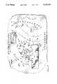
- FIG. 1is a site plan for a typical area contaminated by gasoline, fuel oil or the like showing locations of remediation devices in accordance with the invention
- FIG. 2is a cross sectional view of soil having a veil well, shown partially cut away, installed therein;
- FIG. 3is a cross sectional view of a landfarm of FIG. 1 prior to depositing of contaminated soil;
- FIG. 4is a cross sectional view of soil having a dead man device installed therein for collection of ground water and product;
- FIG. 5is a perspective view of an excavation of a square of contaminated soil of FIG. 1 showing the ledge procedure
- FIG. 6is a tine of a rotary tiller used in treating contaminated soil in the landfarm of FIG. 3;
- FIG. 7is a cross sectional view of a building and supporting oil showing a horizontal well installed in the soil;
- FIG. 8is a perspective view of an injection well system installed in an excavation.
- FIG. 9is a partial and cutaway view of an air manifold used in the process of the invention having a reed for increasing the temperature of air passing therethrough.
- a typical application of the present inventionis in the bioremediation of contaminated soils and groundwater caused by a tank leak of gasoline or other petroleum hydrocarbons at a service station.
- a Contamination Assessment Reportis required when a discharge has been discovered or reported.
- the first step in a Contamination Assessment Reportis to determine if the suspected discharge has in fact occurred and, if so, has it reached the groundwater.
- a monitoring well 13is installed in the area of the suspected discharge and a water sample is collected.
- a soil samplecan be collected from the cuttings coming up the auger which provides a composite sample over the depth of the well.
- a split spoon sampling methodcan be used to collect soil samples from specific depths.
- the water sampleis typically analyzed by conventional means to determine the presence and concentration of a hydrocarbon spill, such as gasoline or diesel fuel. Equivalent conventional tests for soil are also conducted to indicate the presence of a hydrocarbon materials.
- the next stepis to define the horizontal extent thereof.
- the term used to define the area of contaminationis "plume,” and the plume can consist of a free floating fraction on the surface of the groundwater table due to the insolubility of fuel in water and due to the lighter specific gravity, and a dissolved fraction, which is soluble or miscible in water.
- the floating fractionis referred to as "product.”
- the two fractions of pollutantswill travel at varying rates in the groundwater and both fractions travel as a function of the site specific hydrogeology.
- additional monitoring wells 14are installed, and the tops of the wells and the horizontal location of the wells are surveyed. Measurements are then made to determine the depth of water from the top of the well casing. The information is used to generate a water contour map 15 which defines the direction and gradient of groundwater flow.
- a deep monitoring well 16is then installed, sampled, and analyzed, at one or more locations, to define the vertical extent of contamination.
- the analytical data, the flow data and the lithology dataare combined with information obtained during on site investigations and research concerning the source and type of discharges.
- the remaining information needed for a Contamination Assessment Reportalso concerns regional information such as adjacent land uses, nearby potable water wellfield locations, or surface water bodies and drainage features in the area. All of the information is assembled prior to determining what remedial measures should be taken.
- veil wells 20After contamination is verified a plurality of containment wells, referred to as "veil wells" 20 is installed.
- a veil well 20is shown in FIG. 2.
- the veil well 20is designed with perforations and/or slots 21 and is installed into the unsaturated zone of the soil, just above the water table.
- veil wells 20are installed down gradient of the plume and on surrounding sides of the plume as required to surround the plume.
- the locations of the veil well curtainis determined from measurements from monitor wells 16. For example, a measurement of 10 ppm to 50 ppm is considered satisfactory for installation of veil wells.
- a bacteria mixis prepared using ERS Formula 1 bacteria mixed with absorbent screenings.
- the bacteria mixis inserted into veil wells 20 in dry form and water is added to fill veil wells 20. Pressurized air in the range of 15 to 25 psi is then used to force the bacteria into the area down gradient of the contamination.
- the curtainserves to keep the contamination plume from migrating away from the original source of contamination and possibly affecting off-site third parties.
- veil wells 20are determined from simple geometric patterns which result in an even spacing. See FIG. 1.
- Field instrumentationsuch as a Foxboro Organic Vapor Analyzer (OVA) or Drager monitoring device, are used to confirm proper and optimum locations.
- OVAFoxboro Organic Vapor Analyzer
- Drager monitoring deviceare used to confirm proper and optimum locations.
- the landfarm 22is constructed in an area not already contaminated, but with monitoring wells 16 in place downgradient from the proposed landfarm location to detect possible leakage from the landfarm.
- a perimeter berm 23is constructed to prevent stormwater from coming in contact with contaminated soil stored therein and possibly overflowing the landfarm area.
- the landfarm 22uses clean fill for the base and berm construction. Screenings 23 are placed over the base to a depth of about 12 inches with a plastic liner 24 placed over the screenings 23.
- the screenings 23act as a cushion in the landfarm to handle the weight of tilling equipment to be used during soil treatment and also act as an absorbent in the event the liner is breached.
- the liner materialmay be overlapped with two foot seams between sections depending upon the size of the landfarm. Another 12 inch lift or thickness of screenings 25 is then placed on top of the liner 24. Excavated contaminated soil is to be placed in the landfarm 22 over the second lift of screenings 25.
- a leachate collection system 28is also installed in the base of the landfarm to collect any liquids which may be generated in the landfarm 22.
- monitoring well 16-1is down gradient from landfarm 22.
- well 16-1will be continually monitored to detect any leakage from a possible breach of liner 24.
- a dead man 30is shown in FIG. 4 that is used to remove water and product in downgradient areas from the source of contamination.
- a 24 to 36 inch culvert pipe 32 with perforations 33 in a lower portion thereofis installed vertically into the ground and extending about three feet into the water table 34, indicated by arrows D.
- Gravel 36is placed around dead man 30 to allow for the easy flow of water and free product into and through perforations 33.
- Three feet of gravel 38is placed in the center of dead man 30 to allow for water and product flow from below the installation.
- a cover(not shown) is also placed over dead man 30 to prevent accidental or intentional dumping.
- Dead man 30is used to recover free product from the surface of the water table. As will be discussed hereinbelow, free product may be directed toward dead man 30 through the manipulation of the water table contours during blow downs on the site.
- dead men 30are installed downgradient from the area of maximum contamination.
- a series of induction wells 31, similar to veil wells 20,is installed adjacent each dead man 30 approximately five to ten feet away.
- Induction wells 31are initially used to draw out and recover free product after first installed. After free product is recovered, the wells 31 are used as a conduit for pressurized air and the introduction of bacteria mix.
- Air pressureof approximately 500 psi is used in a stripping action, to free contamination products trapped in the soils.
- the duration of application of air pressureis a function of the pore spaces and pore sizes in the unsaturated zone of the soil. Loose sands will allow for more air pressure at longer durations before the soil becomes saturated and a blow back phenomenon occurs in which water is forced back into the well 31.
- the air pressureforces the bacteria mix into the surrounding soil to produce the desired bio-degradation of contaminants.
- the pressurealso moves free product and water in the soil toward dead men 30, permitting recovery therefrom.
- a checkerboard excavation pattern 40is used, as shown in FIG. 1.
- a single bucket-wide hole 41is excavated downgradient of the area of contamination as determined by hydrogeological characters.
- the purpose of the excavation 41is to recover free product from the directly contaminated area and to permit organic vapor analyzer (OVA) sampling on the sidewalls of the excavation to be performed.
- OVAorganic vapor analyzer
- the single bucket wide excavation 41 with OVA testing of the side walls, downgradient of the land farmis performed prior to construction of landfarm 22 and is used to estimate the quantities of soil to be excavated and thus, to determine the size and capacity of the landfarm 22.
- the OVA testingis also done to determine the number of monitoring well 16 installations, and amount of sampling and analysis required.
- the initial excavationis preferably performed in an upgradient square of checkerboard pattern 40, such as square 42.
- Excavating upgradient of the tank farmis an optimal process for all sites because bacteria mix introduced upgradient flows into the area of contamination prior to the excavation of the source of contamination.
- FIG. 4The preferred method of removing heavily contaminated soil in square 42 is shown in FIG. 4, termed a ledge type of excavation, and avoids dewatering the area of excavation.
- a large square 43 of about 20 feet by 20 feetis excavated to produce sidewalls 44 of approximately three feet.
- the next level of excavation 46is dug to just above the water table 47 and is approximately 15 feet by 15 feet. The optimum size and depth of the excavation is dependent on the level of contamination and site specific characteristics.
- the soil excavated from square 42is deposited in landfarm 22 for treatment when the excavated soil is spread within berm 23, the surface is coated with bacteria mix dissolved in water, and tilled by a specially designed rotary tiller.
- the tillerhas tines 50, as seen in FIG. 5, having flattened back bars 52. This tiller design produces a fluffing of the soil, increasing its absorbance of the liquid bacteria. The action of the bacteria quickly reduces the contamination to the 10 ppm to 20 ppm range.
- the cleaned soil from landfarm 40is then used to construct a dike between the excavation 43 and the next square to be excavated.
- the floor of the first sequential excavation 43is graded until it is completely level.
- a six inch layer or lift of screeningsis placed on the bottom of excavation 43 followed by a six inch lift of 3/4 inch rock.
- the flooris leveled with a grade stick. The leveling of the floor of the excavation is critical to the process to prevent any particular area from being inundated with too much bacteria during treatment of the excavation.
- tank 12may be removed.
- Horizontal wells 54may be installed in the area under building 10. Horizontal wells 54 can treat soils up to 800 ppm of hydrocarbon with adequate success. Beyond 800 ppm more bacteria is required and degradation rates slow considerably.
- a culvert pipe 58has a plurality of perforations 61 in its side wall.
- a horizontal section of tubing 57is inserted in pipe 58 and surrounded by rock 59.
- An end section 63includes perforations 62.
- a vertical section of tubing 56includes an air lined fitting 53.
- Horizontal section 57preferably has a 10 degree drop from horizontal.
- the perforations 61are placed in the bottom and top of the horizontal pipe. No holes are placed in the sides of the horizontal well under a building, in order to prevent the hole from collapsing and creating voids under the building.
- a concrete collar(not shown) is set into place around the pipe. Rebar is set into the concrete to further hold horizontal well 54 in place during the air injection process.
- Dry bacteriais placed into horizontal wells 54 in dry form.
- a horizontal well 54is filled with water and 500 psi of air pressure is introduced in a single burst to introduce the water, air and bacteria mix. The process is repeated when a blow back occurs. Repeating the process tends to tamp the soil around the horizontal well so more bacteria can be introduced under lower pressures. It is critical that water be used when introducing air pressure into the horizontal well to prevent the pipe from backing out of the hole as the water forms ducts through the soil.
- the horizontal well 54has been described relative to treating soil under buildings and the like, it may also be used for soil surrounding pattern 40 which may have OVA levels below 500 ppm.
- perforationsare placed in the bottom, sides and top of the pipe 61. Where OVA readings are less than 500 ppm less bacteria is required, and lower pressure can be used. The amount of bacteria mix used will depend on the degree of contamination of the site.
- An air line fitting 53is provided at the upper end of tube 56.
- fitting 53is removed and dry bacteria mix inserted into tube 56.
- the well 54is filled with water and air under pressure is introduced via fitting 53.
- the compressed airis supplied to all wells in the system via a special manifold 65 shown in partial cutaway view in FIG. 9.
- a body 68is connected to the source of compressed air.
- a thin, metallic reed 66is interposed in the air flow such that fingers cut into reed 66 vibrate causing a significant increase in the air temperature.
- the heated airexits manifold 65 via a fitting and hose 67 of reduced diameter, increasing the velocity and temperature.
- the higher temperatureaccelerates the remediation action of the bacteria.
- Horizontal wells 54are also used in areas which have contamination below 500 ppm which is not economical to excavate.
- wells 54are shown in FIG. 1 inserted in the outside walls of excavated squares in pattern 40.
- a special bacteria injection device 70shown in perspective view in FIG. 8, is used.
- the device 70is fabricated from polyvinyl chloride pipe (PVC) and includes input fittings 75 and valves 74.
- a bacteria injection array 72may be in the form of a square of PVC pipe having holes 73 along the sides thereof. Array 72 is fed by a pair of vertical pipes connected to valves 74.
- the device 70is lowered into an excavated square of pattern 50 after the described leveling and treatment of the floor.
- Array 72is covered with a 12 inch lift of 3/4 inch drainfield rock followed by a 12 inch lift of screenings. This allows for good movement of groundwater through the area, allowing the bacteria to move freely through the site.
- Bio-enriched fill from landfarm 22is then placed over the screenings up to subgrade level. Bacteria, mix and water are introduced and air, via a manifold 68, previously described, is used to inject bacteria into the contaminated areas for treating any remaining contamination.
- the second inlet 75serves to control the pressure in the system, and acts as a relief mechanism.
- the device 70is left permanently in the area. If monitoring wells indicate excessing levels of contamination in the future, additional treatment can be provided at minimum cost as discussed below.
- the sitemay be covered with asphalt or concrete and normal business operations can begin on the site again.
- Monitoring wells 16are left located in strategic positions to monitor the effectiveness of the remediation.
- the bacteriawill continue working in the ground to clean the soils and groundwater. Available oxygen is being consumed by the aerobic bacteria left in the ground. When the levels of oxygen get too low, the aerobic bacterial convert to anaerobic bacteria and methane is produced.
- aircan be introduced as needed to continue the site rehabilitation process and methane is controlled by pressure relief valves on the wells.
- the air which is introducedmay still be heated and if monitoring data warrants, more bacteria mix and water may be added.
Landscapes
- Life Sciences & Earth Sciences (AREA)
- Engineering & Computer Science (AREA)
- Environmental & Geological Engineering (AREA)
- Mining & Mineral Resources (AREA)
- Geology (AREA)
- Mycology (AREA)
- Microbiology (AREA)
- Molecular Biology (AREA)
- Health & Medical Sciences (AREA)
- Soil Sciences (AREA)
- General Health & Medical Sciences (AREA)
- Physics & Mathematics (AREA)
- Fluid Mechanics (AREA)
- Biotechnology (AREA)
- Biomedical Technology (AREA)
- General Life Sciences & Earth Sciences (AREA)
- Geochemistry & Mineralogy (AREA)
- Processing Of Solid Wastes (AREA)
Abstract
Description
Claims (19)
Priority Applications (1)
| Application Number | Priority Date | Filing Date | Title |
|---|---|---|---|
| US07/489,174US5120160A (en) | 1990-03-05 | 1990-03-05 | Method and apparatus for confining and reclaiming hydrocarbon contaminated land sites |
Applications Claiming Priority (1)
| Application Number | Priority Date | Filing Date | Title |
|---|---|---|---|
| US07/489,174US5120160A (en) | 1990-03-05 | 1990-03-05 | Method and apparatus for confining and reclaiming hydrocarbon contaminated land sites |
Publications (1)
| Publication Number | Publication Date |
|---|---|
| US5120160Atrue US5120160A (en) | 1992-06-09 |
Family
ID=23942718
Family Applications (1)
| Application Number | Title | Priority Date | Filing Date |
|---|---|---|---|
| US07/489,174Expired - Fee RelatedUS5120160A (en) | 1990-03-05 | 1990-03-05 | Method and apparatus for confining and reclaiming hydrocarbon contaminated land sites |
Country Status (1)
| Country | Link |
|---|---|
| US (1) | US5120160A (en) |
Cited By (38)
| Publication number | Priority date | Publication date | Assignee | Title |
|---|---|---|---|---|
| US5192163A (en)* | 1992-05-29 | 1993-03-09 | Fleming Joseph W | Correction method for contaminated sites |
| US5228804A (en)* | 1992-06-25 | 1993-07-20 | Balch Thomas H | Method and apparatus for hydrocarbon-contaminated soil remediation |
| US5265979A (en)* | 1991-03-25 | 1993-11-30 | Landfill Service Corporation | High efficiency waste placement system for municipal landfills |
| WO1994002421A1 (en)* | 1992-07-16 | 1994-02-03 | Hogen Delman R | Microbial mediated method for soil and water treatment |
| US5286140A (en)* | 1992-12-17 | 1994-02-15 | Petro Environmental Technologies, Inc. | Bioremediation systems and methods |
| USH1337H (en) | 1992-09-21 | 1994-07-05 | The United States Of America As Represented By The Secretary Of The Navy | Process for biodegradatioon of soil contaminants that contain volatile/semivolatile components |
| US5336290A (en)* | 1991-09-27 | 1994-08-09 | Jermstad David B | Semi-solid activated sludge bioremediation of hydrocarbon-affected soil |
| US5346330A (en)* | 1992-05-23 | 1994-09-13 | Ieg Industrie-Engineering Gmbh | Method of yielding oil residues or oil containing liquids from contaminated ground layers |
| US5348422A (en)* | 1993-02-25 | 1994-09-20 | Terranalysis Corporation | Methods for the formation and operation of an in situ process reactor |
| US5356240A (en)* | 1992-12-23 | 1994-10-18 | Schuler Joseph A | Soil gas and moisture removal |
| WO1995021034A1 (en)* | 1992-01-07 | 1995-08-10 | Terra Vac, Inc. | Process for soil decontamination by oxidation and vacuum extraction |
| US5511907A (en)* | 1995-05-12 | 1996-04-30 | Tabasco; Joseph J. | Mobile injection device and method for delivery of remediation materials to underground contaminated soils and water |
| US5543049A (en)* | 1991-02-04 | 1996-08-06 | Delman R. Hogen | Microbial mediated water treatment |
| US5558463A (en)* | 1995-03-21 | 1996-09-24 | Geisel; Donald J. | Soil remediation apparatus and method |
| US5591115A (en)* | 1994-01-12 | 1997-01-07 | K & M Engineering & Consulting Corp. | Barrier for blocking movement of contaminants within an aggregate particulate substrate |
| US5597265A (en)* | 1995-02-01 | 1997-01-28 | Gallo; Bruce M. | Method and apparatus for the in-situ treatment of contamination in soil |
| US5605417A (en)* | 1994-07-18 | 1997-02-25 | The Dragun Corporation | Method and apparatus for improving degradation of an unsecured landfill |
| US5641020A (en)* | 1994-05-20 | 1997-06-24 | University Of Waterloo | Treatment of contaminated water in clays and the like |
| US5646342A (en)* | 1992-03-27 | 1997-07-08 | Schlumberger Technology Corporation | Method of Locating Hydrocarbon reserves |
| US5756304A (en)* | 1995-07-14 | 1998-05-26 | Molecular Solutions | Screening of microorganisms for bioremediation |
| US5829918A (en)* | 1994-03-24 | 1998-11-03 | Chintis; Candice | Method and apparatus for remediating contamination in soils |
| US5885203A (en)* | 1994-06-28 | 1999-03-23 | Les Expertises Environmentales Soconag Inc. | Method of decontaminating soils and/or residues in situ and ex situ combining horizontal radial flow technique and depolluting agents |
| US5893680A (en)* | 1996-04-15 | 1999-04-13 | Lowry; William Edward | Volatile contaminant extraction from subsurface apparatus and method |
| US5984578A (en)* | 1997-04-11 | 1999-11-16 | New Jersey Institute Of Technology | Apparatus and method for in situ removal of contaminants using sonic energy |
| US6024513A (en)* | 1996-11-14 | 2000-02-15 | American Technologies Inc | Aerobic landfill bioreactor |
| US6027284A (en)* | 1997-11-03 | 2000-02-22 | Mcgill University | Method and apparatus for remediation of contaminated soil |
| US6356205B1 (en)* | 1998-11-30 | 2002-03-12 | General Electric | Monitoring, diagnostic, and reporting system and process |
| RU2182049C2 (en)* | 2000-03-27 | 2002-05-10 | Федорив Любомир Васильевич | Oil-contaminated soil recultivation method |
| WO2002064699A2 (en) | 2001-02-14 | 2002-08-22 | M-I L.L.C. | Oleaginous drilling fluid, method of use and bio-remediation of the same to produce a useful soil amendments |
| US6497534B1 (en)* | 2001-07-02 | 2002-12-24 | Dorothy A. Smith | Reduction of soil contamination |
| US6503395B1 (en) | 1999-04-14 | 2003-01-07 | Shell Oil Company | Situ method and apparatus for biodegradation of alkyl ethers and tertiary butyl alcohol |
| US20060112627A1 (en)* | 2004-11-02 | 2006-06-01 | Geisel Donald J | Device, system, and method for remediation of contaminated soil |
| US20100059454A1 (en)* | 2008-09-08 | 2010-03-11 | Q Environmental, Inc. | Method for clean-up of an underground plume contaminated with hydrocarbon leakage, and the like |
| US20140231346A1 (en)* | 2009-07-10 | 2014-08-21 | Richard Lee Aho | Accelerated Processing |
| US8974662B2 (en)* | 2002-10-30 | 2015-03-10 | William J Gannon | Filtration of a pumped hydrocarbon containing liquid |
| JP2016168553A (en)* | 2015-03-13 | 2016-09-23 | 三井住友建設株式会社 | Soil purification system |
| US10065223B2 (en)* | 2015-12-03 | 2018-09-04 | Geo-Bohrtechnik Gmbh | Method and system for the in-situ decontamination of contaminated soils |
| US12411123B2 (en) | 2020-05-15 | 2025-09-09 | Environmental Material Science Inc. | Methods and systems for stimulating and detecting the biological degradation of hydrocarbons and biogeochemical cycles in contaminated soils |
Citations (45)
| Publication number | Priority date | Publication date | Assignee | Title |
|---|---|---|---|---|
| US2769750A (en)* | 1953-03-20 | 1956-11-06 | Texaco Development Corp | Processes employing homogenous mixture of inert adsorbent and substrate |
| US2813821A (en)* | 1955-06-20 | 1957-11-19 | Socony Mobil Oil Co Inc | Treatment of porous materials |
| US3152983A (en)* | 1961-12-12 | 1964-10-13 | Socony Mobil Oil Co Inc | Microbial disposal of oily wastes |
| US3224946A (en)* | 1962-09-21 | 1965-12-21 | Socony Mobil Oil Co Inc | Increasing rate of microbial fermentation with zeolites |
| US3306447A (en)* | 1963-11-15 | 1967-02-28 | Robert B Medeiros | Water purification system |
| US3449247A (en)* | 1965-10-23 | 1969-06-10 | William J Bauer | Process for wet oxidation of combustible waste materials |
| US3470091A (en)* | 1967-02-21 | 1969-09-30 | Dorr Oliver Inc | Treatment of polluted streams in place |
| US3616204A (en)* | 1969-05-28 | 1971-10-26 | Continental Oil Co | Method for soil restoration |
| US3634227A (en)* | 1969-09-09 | 1972-01-11 | Dresser Ind | Oil slick elimination |
| US3705851A (en)* | 1971-11-15 | 1972-12-12 | Robert C Brauer | Waste disposal system |
| US3769164A (en)* | 1970-06-03 | 1973-10-30 | Bioteknika International | Microbial degradation of petroleum |
| US3843517A (en)* | 1970-01-08 | 1974-10-22 | Grace W R & Co | Methods for elimination of oil slicks |
| US3846290A (en)* | 1972-09-29 | 1974-11-05 | Sun Research Development | Reclamation of hydrocarbon contaminated ground waters |
| US3856667A (en)* | 1970-06-03 | 1974-12-24 | Bioteknika Int Inc | Microbial degradation of petroleum |
| US3870599A (en)* | 1970-06-03 | 1975-03-11 | Bioteknika International | Microbial degradation of petroleum |
| US3871957A (en)* | 1973-05-09 | 1975-03-18 | Exxon Research Engineering Co | Use of microorganisms to disperse and degrade oil spills |
| US3871956A (en)* | 1970-06-03 | 1975-03-18 | Bioteknika International | Microbial degradation of petroleum |
| US4050907A (en)* | 1976-07-09 | 1977-09-27 | Brimhall George H | Organic waste treating and conversion system |
| US4086167A (en)* | 1977-01-10 | 1978-04-25 | Enso-Gutzeit Osakeyhtio | Biofilter |
| US4171921A (en)* | 1976-06-09 | 1979-10-23 | Morfeldt Carl Olof | Method for preventing the contamination of subsoil water from products deposited on the ground or in underground cavities |
| US4194855A (en)* | 1978-03-27 | 1980-03-25 | Hanns Egger | Method for storing waste materials and their combustion residues in a manner harmless to underground water |
| US4201663A (en)* | 1978-09-07 | 1980-05-06 | Dornbush James N | Method and apparatus for the enhanced treatment of food processing waste waters using aerobic microorganisms |
| US4288174A (en)* | 1979-09-10 | 1981-09-08 | Laws Awbrey C | System for groundwater flow control |
| US4296884A (en)* | 1979-01-23 | 1981-10-27 | True Temper Corporation | Containment reservoir and method |
| US4297122A (en)* | 1979-04-18 | 1981-10-27 | Bio-Group, Inc. | Process for the biological degradation of organic-containing waste matter |
| US4333831A (en)* | 1980-12-22 | 1982-06-08 | Petzinger Manfred W A | Evaporation septic tank sewage system |
| US4385121A (en)* | 1981-10-07 | 1983-05-24 | Chevron Research Company | Medium and process for disposing of hydrocarbon wastes |
| US4396402A (en)* | 1980-06-23 | 1983-08-02 | Institute Of Gas Technology | Gas production by accelerated bioleaching of organic materials |
| US4401569A (en)* | 1981-07-09 | 1983-08-30 | Groundwater Decontamination Systems, Inc. | Method and apparatus for treating hydrocarbon and halogenated hydrocarbon contaminated ground and ground water |
| US4404516A (en)* | 1980-10-29 | 1983-09-13 | Johnson Jr Victor R | System for detecting leaks from liquid-containing reservoirs and conduits |
| US4414333A (en)* | 1976-09-01 | 1983-11-08 | Snamprogetti, S.P.A. | Compositions for depolluting fresh water and salt water bodies |
| US4415662A (en)* | 1981-07-30 | 1983-11-15 | Thirumalachar Mandayam J | Microbial degradation of petroleum materials |
| US4415661A (en)* | 1981-07-30 | 1983-11-15 | Thirumalachar Mandayam J | Microbial degradation of petroleum materials |
| US4469176A (en)* | 1983-06-08 | 1984-09-04 | Getty Synthetic Fuels, Inc. | Landfill gas recovery system and method with pressure symmetry |
| US4493895A (en)* | 1981-09-24 | 1985-01-15 | Occidental Chemical Corporation | Microbial degradation of obnoxious organic wastes into innocuous materials |
| US4521515A (en)* | 1981-10-21 | 1985-06-04 | Seiken Kai Foundation Juridical Person | Bacterial strain for purifying hydrocarbons pollution and purification process |
| US4584102A (en)* | 1985-09-05 | 1986-04-22 | Bogart John D | Process for the biological degradation of hazardous waste by-products |
| US4624604A (en)* | 1981-11-23 | 1986-11-25 | Environmental Design, Inc. | Groundwater protection system |
| US4637462A (en)* | 1985-06-04 | 1987-01-20 | Grable Donovan B | Liquid mud ring control of underground liquids |
| US4670148A (en)* | 1984-11-10 | 1987-06-02 | Reinhard Schneider | Apparatus and method for withdrawing gaseous decomposition products from a refuse dump |
| US4678582A (en)* | 1986-01-24 | 1987-07-07 | Lavigne Ronald L | Treatment system for landfill leachate |
| US4713343A (en)* | 1985-08-29 | 1987-12-15 | The United States Of America As Represented By The Administrator Of The U.S. Environmental Protection Agency | Biodegradation of halogenated aliphatic hydrocarbons |
| US4765902A (en)* | 1987-09-25 | 1988-08-23 | Chevron Research Company | Process for in situ biodegradation of hydrocarbon contaminated soil |
| US4849360A (en)* | 1986-07-30 | 1989-07-18 | International Technology Corporation | Apparatus and method for confining and decontaminating soil |
| US4850745A (en)* | 1988-06-17 | 1989-07-25 | Sybron Chemicals, Inc. | Bioremediation system |
- 1990
- 1990-03-05USUS07/489,174patent/US5120160A/ennot_activeExpired - Fee Related
Patent Citations (45)
| Publication number | Priority date | Publication date | Assignee | Title |
|---|---|---|---|---|
| US2769750A (en)* | 1953-03-20 | 1956-11-06 | Texaco Development Corp | Processes employing homogenous mixture of inert adsorbent and substrate |
| US2813821A (en)* | 1955-06-20 | 1957-11-19 | Socony Mobil Oil Co Inc | Treatment of porous materials |
| US3152983A (en)* | 1961-12-12 | 1964-10-13 | Socony Mobil Oil Co Inc | Microbial disposal of oily wastes |
| US3224946A (en)* | 1962-09-21 | 1965-12-21 | Socony Mobil Oil Co Inc | Increasing rate of microbial fermentation with zeolites |
| US3306447A (en)* | 1963-11-15 | 1967-02-28 | Robert B Medeiros | Water purification system |
| US3449247A (en)* | 1965-10-23 | 1969-06-10 | William J Bauer | Process for wet oxidation of combustible waste materials |
| US3470091A (en)* | 1967-02-21 | 1969-09-30 | Dorr Oliver Inc | Treatment of polluted streams in place |
| US3616204A (en)* | 1969-05-28 | 1971-10-26 | Continental Oil Co | Method for soil restoration |
| US3634227A (en)* | 1969-09-09 | 1972-01-11 | Dresser Ind | Oil slick elimination |
| US3843517A (en)* | 1970-01-08 | 1974-10-22 | Grace W R & Co | Methods for elimination of oil slicks |
| US3769164A (en)* | 1970-06-03 | 1973-10-30 | Bioteknika International | Microbial degradation of petroleum |
| US3871956A (en)* | 1970-06-03 | 1975-03-18 | Bioteknika International | Microbial degradation of petroleum |
| US3856667A (en)* | 1970-06-03 | 1974-12-24 | Bioteknika Int Inc | Microbial degradation of petroleum |
| US3870599A (en)* | 1970-06-03 | 1975-03-11 | Bioteknika International | Microbial degradation of petroleum |
| US3705851A (en)* | 1971-11-15 | 1972-12-12 | Robert C Brauer | Waste disposal system |
| US3846290A (en)* | 1972-09-29 | 1974-11-05 | Sun Research Development | Reclamation of hydrocarbon contaminated ground waters |
| US3871957A (en)* | 1973-05-09 | 1975-03-18 | Exxon Research Engineering Co | Use of microorganisms to disperse and degrade oil spills |
| US4171921A (en)* | 1976-06-09 | 1979-10-23 | Morfeldt Carl Olof | Method for preventing the contamination of subsoil water from products deposited on the ground or in underground cavities |
| US4050907A (en)* | 1976-07-09 | 1977-09-27 | Brimhall George H | Organic waste treating and conversion system |
| US4414333A (en)* | 1976-09-01 | 1983-11-08 | Snamprogetti, S.P.A. | Compositions for depolluting fresh water and salt water bodies |
| US4086167A (en)* | 1977-01-10 | 1978-04-25 | Enso-Gutzeit Osakeyhtio | Biofilter |
| US4194855A (en)* | 1978-03-27 | 1980-03-25 | Hanns Egger | Method for storing waste materials and their combustion residues in a manner harmless to underground water |
| US4201663A (en)* | 1978-09-07 | 1980-05-06 | Dornbush James N | Method and apparatus for the enhanced treatment of food processing waste waters using aerobic microorganisms |
| US4296884A (en)* | 1979-01-23 | 1981-10-27 | True Temper Corporation | Containment reservoir and method |
| US4297122A (en)* | 1979-04-18 | 1981-10-27 | Bio-Group, Inc. | Process for the biological degradation of organic-containing waste matter |
| US4288174A (en)* | 1979-09-10 | 1981-09-08 | Laws Awbrey C | System for groundwater flow control |
| US4396402A (en)* | 1980-06-23 | 1983-08-02 | Institute Of Gas Technology | Gas production by accelerated bioleaching of organic materials |
| US4404516A (en)* | 1980-10-29 | 1983-09-13 | Johnson Jr Victor R | System for detecting leaks from liquid-containing reservoirs and conduits |
| US4333831A (en)* | 1980-12-22 | 1982-06-08 | Petzinger Manfred W A | Evaporation septic tank sewage system |
| US4401569A (en)* | 1981-07-09 | 1983-08-30 | Groundwater Decontamination Systems, Inc. | Method and apparatus for treating hydrocarbon and halogenated hydrocarbon contaminated ground and ground water |
| US4415661A (en)* | 1981-07-30 | 1983-11-15 | Thirumalachar Mandayam J | Microbial degradation of petroleum materials |
| US4415662A (en)* | 1981-07-30 | 1983-11-15 | Thirumalachar Mandayam J | Microbial degradation of petroleum materials |
| US4493895A (en)* | 1981-09-24 | 1985-01-15 | Occidental Chemical Corporation | Microbial degradation of obnoxious organic wastes into innocuous materials |
| US4385121A (en)* | 1981-10-07 | 1983-05-24 | Chevron Research Company | Medium and process for disposing of hydrocarbon wastes |
| US4521515A (en)* | 1981-10-21 | 1985-06-04 | Seiken Kai Foundation Juridical Person | Bacterial strain for purifying hydrocarbons pollution and purification process |
| US4624604A (en)* | 1981-11-23 | 1986-11-25 | Environmental Design, Inc. | Groundwater protection system |
| US4469176A (en)* | 1983-06-08 | 1984-09-04 | Getty Synthetic Fuels, Inc. | Landfill gas recovery system and method with pressure symmetry |
| US4670148A (en)* | 1984-11-10 | 1987-06-02 | Reinhard Schneider | Apparatus and method for withdrawing gaseous decomposition products from a refuse dump |
| US4637462A (en)* | 1985-06-04 | 1987-01-20 | Grable Donovan B | Liquid mud ring control of underground liquids |
| US4713343A (en)* | 1985-08-29 | 1987-12-15 | The United States Of America As Represented By The Administrator Of The U.S. Environmental Protection Agency | Biodegradation of halogenated aliphatic hydrocarbons |
| US4584102A (en)* | 1985-09-05 | 1986-04-22 | Bogart John D | Process for the biological degradation of hazardous waste by-products |
| US4678582A (en)* | 1986-01-24 | 1987-07-07 | Lavigne Ronald L | Treatment system for landfill leachate |
| US4849360A (en)* | 1986-07-30 | 1989-07-18 | International Technology Corporation | Apparatus and method for confining and decontaminating soil |
| US4765902A (en)* | 1987-09-25 | 1988-08-23 | Chevron Research Company | Process for in situ biodegradation of hydrocarbon contaminated soil |
| US4850745A (en)* | 1988-06-17 | 1989-07-25 | Sybron Chemicals, Inc. | Bioremediation system |
Cited By (52)
| Publication number | Priority date | Publication date | Assignee | Title |
|---|---|---|---|---|
| US5543049A (en)* | 1991-02-04 | 1996-08-06 | Delman R. Hogen | Microbial mediated water treatment |
| US5667673A (en)* | 1991-02-04 | 1997-09-16 | Hogen; Delman R. | Microbial mediated water treatment |
| US5265979A (en)* | 1991-03-25 | 1993-11-30 | Landfill Service Corporation | High efficiency waste placement system for municipal landfills |
| US5336290A (en)* | 1991-09-27 | 1994-08-09 | Jermstad David B | Semi-solid activated sludge bioremediation of hydrocarbon-affected soil |
| AU693430B2 (en)* | 1992-01-07 | 1998-07-02 | Terra Vac, Inc. | Process for soil decontamination by oxidation and vacuum extraction |
| WO1995021034A1 (en)* | 1992-01-07 | 1995-08-10 | Terra Vac, Inc. | Process for soil decontamination by oxidation and vacuum extraction |
| US5646342A (en)* | 1992-03-27 | 1997-07-08 | Schlumberger Technology Corporation | Method of Locating Hydrocarbon reserves |
| US5346330A (en)* | 1992-05-23 | 1994-09-13 | Ieg Industrie-Engineering Gmbh | Method of yielding oil residues or oil containing liquids from contaminated ground layers |
| US5192163A (en)* | 1992-05-29 | 1993-03-09 | Fleming Joseph W | Correction method for contaminated sites |
| US5228804A (en)* | 1992-06-25 | 1993-07-20 | Balch Thomas H | Method and apparatus for hydrocarbon-contaminated soil remediation |
| WO1994002421A1 (en)* | 1992-07-16 | 1994-02-03 | Hogen Delman R | Microbial mediated method for soil and water treatment |
| USH1337H (en) | 1992-09-21 | 1994-07-05 | The United States Of America As Represented By The Secretary Of The Navy | Process for biodegradatioon of soil contaminants that contain volatile/semivolatile components |
| US5286140A (en)* | 1992-12-17 | 1994-02-15 | Petro Environmental Technologies, Inc. | Bioremediation systems and methods |
| US5356240A (en)* | 1992-12-23 | 1994-10-18 | Schuler Joseph A | Soil gas and moisture removal |
| US5348422A (en)* | 1993-02-25 | 1994-09-20 | Terranalysis Corporation | Methods for the formation and operation of an in situ process reactor |
| US5591115A (en)* | 1994-01-12 | 1997-01-07 | K & M Engineering & Consulting Corp. | Barrier for blocking movement of contaminants within an aggregate particulate substrate |
| US5829918A (en)* | 1994-03-24 | 1998-11-03 | Chintis; Candice | Method and apparatus for remediating contamination in soils |
| US5641020A (en)* | 1994-05-20 | 1997-06-24 | University Of Waterloo | Treatment of contaminated water in clays and the like |
| US5885203A (en)* | 1994-06-28 | 1999-03-23 | Les Expertises Environmentales Soconag Inc. | Method of decontaminating soils and/or residues in situ and ex situ combining horizontal radial flow technique and depolluting agents |
| US5605417A (en)* | 1994-07-18 | 1997-02-25 | The Dragun Corporation | Method and apparatus for improving degradation of an unsecured landfill |
| US5597265A (en)* | 1995-02-01 | 1997-01-28 | Gallo; Bruce M. | Method and apparatus for the in-situ treatment of contamination in soil |
| US5558463A (en)* | 1995-03-21 | 1996-09-24 | Geisel; Donald J. | Soil remediation apparatus and method |
| US5511907A (en)* | 1995-05-12 | 1996-04-30 | Tabasco; Joseph J. | Mobile injection device and method for delivery of remediation materials to underground contaminated soils and water |
| US5756304A (en)* | 1995-07-14 | 1998-05-26 | Molecular Solutions | Screening of microorganisms for bioremediation |
| US5893680A (en)* | 1996-04-15 | 1999-04-13 | Lowry; William Edward | Volatile contaminant extraction from subsurface apparatus and method |
| US6364572B1 (en)* | 1996-11-14 | 2002-04-02 | American Technologies, Inc. | Aerobic landfill bioreactor |
| US6024513A (en)* | 1996-11-14 | 2000-02-15 | American Technologies Inc | Aerobic landfill bioreactor |
| US5984578A (en)* | 1997-04-11 | 1999-11-16 | New Jersey Institute Of Technology | Apparatus and method for in situ removal of contaminants using sonic energy |
| US6027284A (en)* | 1997-11-03 | 2000-02-22 | Mcgill University | Method and apparatus for remediation of contaminated soil |
| US6356205B1 (en)* | 1998-11-30 | 2002-03-12 | General Electric | Monitoring, diagnostic, and reporting system and process |
| US6808632B2 (en) | 1999-04-14 | 2004-10-26 | Shell Oil Company | In situ method and apparatus for biodegradation of alkyl ethers and tertiary butyl alcohol |
| US20050020453A1 (en)* | 1999-04-14 | 2005-01-27 | Salanitro Joseph Patrick | In situ method and apparatus for biodegradation of alkyl ethers and tertiary butyl alcohol |
| US7255791B2 (en) | 1999-04-14 | 2007-08-14 | Shell Oil Company | In situ method and apparatus for biodegradation of alkyl ethers and tertiary butyl alcohol |
| US6503395B1 (en) | 1999-04-14 | 2003-01-07 | Shell Oil Company | Situ method and apparatus for biodegradation of alkyl ethers and tertiary butyl alcohol |
| US20030150799A1 (en)* | 1999-04-14 | 2003-08-14 | Salanitro Joseph Patrick | In situ method and apparatus for biodegradation of alkyl ethers and tertiary butyl alcohol |
| US6776910B2 (en)* | 1999-04-14 | 2004-08-17 | Shell Oil Company | In situ method and apparatus for biodegradation of alkyl ethers and tertiary butyl alcohol |
| RU2182049C2 (en)* | 2000-03-27 | 2002-05-10 | Федорив Любомир Васильевич | Oil-contaminated soil recultivation method |
| US6838082B2 (en) | 2001-02-14 | 2005-01-04 | M-I Llc | Vermiculture compositions |
| EP2458136A1 (en) | 2001-02-14 | 2012-05-30 | M-I L.L.C. | Method of bio-remediating wellbore cuttings |
| US20050090405A1 (en)* | 2001-02-14 | 2005-04-28 | Frederick Growcock | Vermiculture compositions |
| WO2002064699A2 (en) | 2001-02-14 | 2002-08-22 | M-I L.L.C. | Oleaginous drilling fluid, method of use and bio-remediation of the same to produce a useful soil amendments |
| US8735141B2 (en) | 2001-02-14 | 2014-05-27 | M-I L.L.C. | Vermiculture compositions |
| US6497534B1 (en)* | 2001-07-02 | 2002-12-24 | Dorothy A. Smith | Reduction of soil contamination |
| US8974662B2 (en)* | 2002-10-30 | 2015-03-10 | William J Gannon | Filtration of a pumped hydrocarbon containing liquid |
| US20060112627A1 (en)* | 2004-11-02 | 2006-06-01 | Geisel Donald J | Device, system, and method for remediation of contaminated soil |
| US7175366B2 (en) | 2004-11-02 | 2007-02-13 | Geisel Donald J | Device, system, and method for remediation of contaminated soil |
| US20100059454A1 (en)* | 2008-09-08 | 2010-03-11 | Q Environmental, Inc. | Method for clean-up of an underground plume contaminated with hydrocarbon leakage, and the like |
| US20140231346A1 (en)* | 2009-07-10 | 2014-08-21 | Richard Lee Aho | Accelerated Processing |
| US9902638B2 (en)* | 2009-07-10 | 2018-02-27 | Richard Lee Aho | Accelerated processing |
| JP2016168553A (en)* | 2015-03-13 | 2016-09-23 | 三井住友建設株式会社 | Soil purification system |
| US10065223B2 (en)* | 2015-12-03 | 2018-09-04 | Geo-Bohrtechnik Gmbh | Method and system for the in-situ decontamination of contaminated soils |
| US12411123B2 (en) | 2020-05-15 | 2025-09-09 | Environmental Material Science Inc. | Methods and systems for stimulating and detecting the biological degradation of hydrocarbons and biogeochemical cycles in contaminated soils |
Similar Documents
| Publication | Publication Date | Title |
|---|---|---|
| US5120160A (en) | Method and apparatus for confining and reclaiming hydrocarbon contaminated land sites | |
| US4582611A (en) | Soil decontamination with wick drains | |
| US5037240A (en) | In-situ soil treatment process | |
| Fountain et al. | A controlled field test of surfactant‐enhanced aquifer remediation | |
| US5733067A (en) | Method and system for bioremediation of contaminated soil using inoculated support spheres | |
| Brown | Treatment of petroleum hydrocarbons in ground water by air sparging | |
| US5879107A (en) | Underground contamination in situ treatment system | |
| Shackelford et al. | Geoenvironmental engineering for in situ remediation | |
| US5403119A (en) | Perforated piling for soil remediation | |
| Cohen et al. | Design guidelines for conventional pump-and-treat systems | |
| Reddy | Physical and chemical groundwater remediation technologies | |
| Adam | US EPA Contaminated Site Cleanup Information (CLU-IN) | |
| Minugh et al. | A case history: Cleanup of a subsurface leak of refined product | |
| Waltz | Utilization of closed-in-place underground storage tanks in the remediation of contaminated soils and groundwater | |
| Schrauf et al. | Alternative method of groundwater sparging for petroleum hydrocarbon remediation | |
| Malot | Cleanup of a gasoline contaminated site using vacuum extraction technology | |
| Bondoc | An overview of alternative remediation methods for groundwater contamination | |
| Ola et al. | Remediation of hydrocarbon contaminated sites | |
| Marley et al. | Successfully applying sparging technologies | |
| Kittel et al. | In situ Remediation of Low-Volatility Fuels Using Bioventing Technology | |
| Reynolds et al. | Bioremediation of hydrocarbon-contaminated soils and groundwater in northern climates | |
| Nordin et al. | Remediation Cleanup Options for the Hoe Creek UCG Site | |
| Ward | Leaking underground storage tanks: site characterization, remediation and risk assessment | |
| Edison | Alternatives Analysis Report Consolidated Edison, Former MGP East 115th Street, New York, New York NYSDEC Site# V00540-2 | |
| Cohen et al. | Ground water issue |
Legal Events
| Date | Code | Title | Description |
|---|---|---|---|
| AS | Assignment | Owner name:ENVIRONMENTAL BIO-REMEDIATION INT'L. CORP., A CORP Free format text:ASSIGNMENT OF ASSIGNORS INTEREST.;ASSIGNOR:SCHWENGEL, ERICH;REEL/FRAME:005279/0620 Effective date:19900305 | |
| AS | Assignment | Owner name:ENVIRONMENTAL RECLAMATION SYSTEMS, INC.,, FLORIDA Free format text:ASSIGNMENT OF ASSIGNORS INTEREST.;ASSIGNOR:ENVIRONMENTAL BIO-REMEDIATION INTERNATIONAL CORP.;REEL/FRAME:005700/0739 Effective date:19910502 | |
| AS | Assignment | Owner name:RECLAMATION BIOTECH INC., A CORP. OF FLORIDA Free format text:ASSIGNMENT OF ASSIGNORS INTEREST.;ASSIGNOR:ENVIRONMENTAL RECLAMATION SYSTEMS INC., A CORP. OF FLORIDA;REEL/FRAME:006125/0501 Effective date:19920508 | |
| AS | Assignment | Owner name:RECLAMATION BIOTECH INC., NEW YORK Free format text:ASSIGNMENT OF ASSIGNORS INTEREST.;ASSIGNOR:ENVIRONMENTAL RECLAMATION SYSTEMS INC., A FL CORP.;REEL/FRAME:006155/0045 Effective date:19920610 | |
| FPAY | Fee payment | Year of fee payment:4 | |
| REMI | Maintenance fee reminder mailed | ||
| LAPS | Lapse for failure to pay maintenance fees | ||
| FP | Lapsed due to failure to pay maintenance fee | Effective date:20000609 | |
| STCH | Information on status: patent discontinuation | Free format text:PATENT EXPIRED DUE TO NONPAYMENT OF MAINTENANCE FEES UNDER 37 CFR 1.362 |