US5120109A - Motor vehicle seat - Google Patents
Motor vehicle seatDownload PDFInfo
- Publication number
- US5120109A US5120109AUS07/383,140US38314089AUS5120109AUS 5120109 AUS5120109 AUS 5120109AUS 38314089 AUS38314089 AUS 38314089AUS 5120109 AUS5120109 AUS 5120109A
- Authority
- US
- United States
- Prior art keywords
- backrest
- frame
- transverse axis
- support structure
- relative
- Prior art date
- Legal status (The legal status is an assumption and is not a legal conclusion. Google has not performed a legal analysis and makes no representation as to the accuracy of the status listed.)
- Expired - Lifetime
Links
- 208000007623LordosisDiseases0.000claimsdescription26
- 230000004044responseEffects0.000claimsdescription3
- 210000004705lumbosacral regionAnatomy0.000abstractdescription5
- 230000006978adaptationEffects0.000abstractdescription2
- 210000004197pelvisAnatomy0.000abstractdescription2
- 208000028571Occupational diseaseDiseases0.000abstract1
- 206010036086PolymenorrhoeaDiseases0.000abstract1
- 239000002184metalSubstances0.000description5
- 210000002414legAnatomy0.000description4
- 230000008859changeEffects0.000description3
- 238000006073displacement reactionMethods0.000description3
- 238000000034methodMethods0.000description3
- 239000003638chemical reducing agentSubstances0.000description2
- 238000010276constructionMethods0.000description2
- 230000009471actionEffects0.000description1
- 230000003213activating effectEffects0.000description1
- 230000004075alterationEffects0.000description1
- 210000003484anatomyAnatomy0.000description1
- 238000005452bendingMethods0.000description1
- 238000006243chemical reactionMethods0.000description1
- 238000007796conventional methodMethods0.000description1
- 230000008030eliminationEffects0.000description1
- 238000003379elimination reactionMethods0.000description1
- 238000005516engineering processMethods0.000description1
- 206010016256fatigueDiseases0.000description1
- 239000000463materialSubstances0.000description1
- 230000004962physiological conditionEffects0.000description1
- 229920003023plasticPolymers0.000description1
- 239000004033plasticSubstances0.000description1
- 230000002035prolonged effectEffects0.000description1
- 230000002787reinforcementEffects0.000description1
- 230000003014reinforcing effectEffects0.000description1
- 238000005096rolling processMethods0.000description1
- 210000000689upper legAnatomy0.000description1
Images


Classifications
- B—PERFORMING OPERATIONS; TRANSPORTING
- B60—VEHICLES IN GENERAL
- B60N—SEATS SPECIALLY ADAPTED FOR VEHICLES; VEHICLE PASSENGER ACCOMMODATION NOT OTHERWISE PROVIDED FOR
- B60N2/00—Seats specially adapted for vehicles; Arrangement or mounting of seats in vehicles
- B60N2/64—Back-rests or cushions
- B60N2/66—Lumbar supports
- B—PERFORMING OPERATIONS; TRANSPORTING
- B60—VEHICLES IN GENERAL
- B60N—SEATS SPECIALLY ADAPTED FOR VEHICLES; VEHICLE PASSENGER ACCOMMODATION NOT OTHERWISE PROVIDED FOR
- B60N2/00—Seats specially adapted for vehicles; Arrangement or mounting of seats in vehicles
- B60N2/02—Seats specially adapted for vehicles; Arrangement or mounting of seats in vehicles the seat or part thereof being movable, e.g. adjustable
- B60N2/04—Seats specially adapted for vehicles; Arrangement or mounting of seats in vehicles the seat or part thereof being movable, e.g. adjustable the whole seat being movable
- B60N2/16—Seats specially adapted for vehicles; Arrangement or mounting of seats in vehicles the seat or part thereof being movable, e.g. adjustable the whole seat being movable height-adjustable
- B60N2/18—Seats specially adapted for vehicles; Arrangement or mounting of seats in vehicles the seat or part thereof being movable, e.g. adjustable the whole seat being movable height-adjustable the front or the rear portion of the seat being adjustable, e.g. independently of each other
- B60N2/1803—Seats specially adapted for vehicles; Arrangement or mounting of seats in vehicles the seat or part thereof being movable, e.g. adjustable the whole seat being movable height-adjustable the front or the rear portion of the seat being adjustable, e.g. independently of each other with independent front and/or rear adjustment
- B—PERFORMING OPERATIONS; TRANSPORTING
- B60—VEHICLES IN GENERAL
- B60N—SEATS SPECIALLY ADAPTED FOR VEHICLES; VEHICLE PASSENGER ACCOMMODATION NOT OTHERWISE PROVIDED FOR
- B60N2/00—Seats specially adapted for vehicles; Arrangement or mounting of seats in vehicles
- B60N2/02—Seats specially adapted for vehicles; Arrangement or mounting of seats in vehicles the seat or part thereof being movable, e.g. adjustable
- B60N2/04—Seats specially adapted for vehicles; Arrangement or mounting of seats in vehicles the seat or part thereof being movable, e.g. adjustable the whole seat being movable
- B60N2/16—Seats specially adapted for vehicles; Arrangement or mounting of seats in vehicles the seat or part thereof being movable, e.g. adjustable the whole seat being movable height-adjustable
- B60N2/18—Seats specially adapted for vehicles; Arrangement or mounting of seats in vehicles the seat or part thereof being movable, e.g. adjustable the whole seat being movable height-adjustable the front or the rear portion of the seat being adjustable, e.g. independently of each other
- B60N2/1807—Seats specially adapted for vehicles; Arrangement or mounting of seats in vehicles the seat or part thereof being movable, e.g. adjustable the whole seat being movable height-adjustable the front or the rear portion of the seat being adjustable, e.g. independently of each other characterised by the cinematic
- B60N2/181—Rods
- B—PERFORMING OPERATIONS; TRANSPORTING
- B60—VEHICLES IN GENERAL
- B60N—SEATS SPECIALLY ADAPTED FOR VEHICLES; VEHICLE PASSENGER ACCOMMODATION NOT OTHERWISE PROVIDED FOR
- B60N2/00—Seats specially adapted for vehicles; Arrangement or mounting of seats in vehicles
- B60N2/02—Seats specially adapted for vehicles; Arrangement or mounting of seats in vehicles the seat or part thereof being movable, e.g. adjustable
- B60N2/04—Seats specially adapted for vehicles; Arrangement or mounting of seats in vehicles the seat or part thereof being movable, e.g. adjustable the whole seat being movable
- B60N2/16—Seats specially adapted for vehicles; Arrangement or mounting of seats in vehicles the seat or part thereof being movable, e.g. adjustable the whole seat being movable height-adjustable
- B60N2/18—Seats specially adapted for vehicles; Arrangement or mounting of seats in vehicles the seat or part thereof being movable, e.g. adjustable the whole seat being movable height-adjustable the front or the rear portion of the seat being adjustable, e.g. independently of each other
- B60N2/185—Seats specially adapted for vehicles; Arrangement or mounting of seats in vehicles the seat or part thereof being movable, e.g. adjustable the whole seat being movable height-adjustable the front or the rear portion of the seat being adjustable, e.g. independently of each other characterised by the drive mechanism
- B—PERFORMING OPERATIONS; TRANSPORTING
- B60—VEHICLES IN GENERAL
- B60N—SEATS SPECIALLY ADAPTED FOR VEHICLES; VEHICLE PASSENGER ACCOMMODATION NOT OTHERWISE PROVIDED FOR
- B60N2/00—Seats specially adapted for vehicles; Arrangement or mounting of seats in vehicles
- B60N2/02—Seats specially adapted for vehicles; Arrangement or mounting of seats in vehicles the seat or part thereof being movable, e.g. adjustable
- B60N2/22—Seats specially adapted for vehicles; Arrangement or mounting of seats in vehicles the seat or part thereof being movable, e.g. adjustable the back-rest being adjustable
- B60N2/2222—Seats specially adapted for vehicles; Arrangement or mounting of seats in vehicles the seat or part thereof being movable, e.g. adjustable the back-rest being adjustable the back-rest having two or more parts
- B—PERFORMING OPERATIONS; TRANSPORTING
- B60—VEHICLES IN GENERAL
- B60N—SEATS SPECIALLY ADAPTED FOR VEHICLES; VEHICLE PASSENGER ACCOMMODATION NOT OTHERWISE PROVIDED FOR
- B60N2/00—Seats specially adapted for vehicles; Arrangement or mounting of seats in vehicles
- B60N2/62—Thigh-rests
- B—PERFORMING OPERATIONS; TRANSPORTING
- B60—VEHICLES IN GENERAL
- B60N—SEATS SPECIALLY ADAPTED FOR VEHICLES; VEHICLE PASSENGER ACCOMMODATION NOT OTHERWISE PROVIDED FOR
- B60N2/00—Seats specially adapted for vehicles; Arrangement or mounting of seats in vehicles
- B60N2/64—Back-rests or cushions
- B60N2/66—Lumbar supports
- B60N2/666—Lumbar supports vertically adjustable
- B—PERFORMING OPERATIONS; TRANSPORTING
- B60—VEHICLES IN GENERAL
- B60N—SEATS SPECIALLY ADAPTED FOR VEHICLES; VEHICLE PASSENGER ACCOMMODATION NOT OTHERWISE PROVIDED FOR
- B60N2/00—Seats specially adapted for vehicles; Arrangement or mounting of seats in vehicles
- B60N2/80—Head-rests
- B60N2/806—Head-rests movable or adjustable
- B60N2/838—Tiltable
- B60N2/853—Tiltable characterised by their adjusting mechanisms, e.g. electric motors
Definitions
- the present inventionrelates to motor vehicle seats of the known type comprising:
- a squabincluding a frame which is intended to be mounted on the floor of the motor vehicle with the interposition of guide means for adjusting the position of the seat longitudinally of the motor vehicle, and
- a backrestincluding a frame which is articulated at the bottom, about a first transverse axis, to a support structure fixed to the movable part of the longitudinal guide means, by means of a device which enables the angular position of the backrest to be adjusted relative to the transverse axis.
- a different curvature of the backrest in the lumbar regiongenerally forces the user to change the position of his back relative to the length of the motor vehicle, or causes a change in the distribution of the pressure exerted by the backrest on the back. It is essential, however, that the pressure distribution remains substantially constant under all conditions of use, in order to avoid the alteration of the optimum physiological conditions after a prolonged period in the seat.
- another problemresults from the considerable differences which may exist between the physical characteristics of different users, particularly with reference to the vertical distance between the lordosis of the neck and the lumbar lordosis.
- Another problem common to all prior-art seatsconsists of the fact that the iliac region of the seated person is situated in correspondence with the angle formed between the squab and the backrest and therefore lacks support since the bulk of the adjacent parts of the padding of the backrest and the squab leaves an empty space in correspondence with the angle, which is not occupied by the body of the seated person.
- the object of the present inventionis to produce a motor vehicle seat which enables the satisfactory resolution of all the problems indicated above, and particularly of the problem relating to the correct support of the seated person's back.
- the seat according to the inventiona primarily characterised by the fact that it has at least the following further characteristics:
- the frame of the backrestincludes an upper portion which is articulated to the rest of the frame of the backrest about a second transverse axis by means of a device which enables the angular position of the upper portion to be adjusted relative to the second transverse axis, the part of the backrest associated with the upper portion being intended to support the body of the seated person substantially in correspondence with the lordosis of the vertebral column in the upper region of the back;
- the portion of the frame of the backrest which is situated beneath the second axis of articulationis composed of at least two parts mounted for sliding relative to each other vertically of the backrest and actuator means are provided for adjusting the relative positions of these parts and hence the vertical position of the second transverse articulation axis.
- the usercan easily adapt the backrest of the seat according to the invention to his own particular characteristics so as to obtain correct support in correspondence with the lordosis of the neck.
- the presence of an articulated upper part in the frame of the backrestactually enables the upper part to be inclined forwardly, so as to achieve the correct support of the region of the back which is situated at a height intermediate the level of the shoulder blades and the level of the neck.
- the fact that the vertical position of the second axis of articulation can be variedenables this adaptation to be made to any physical configuration and particularly to any distance between the lordosis of the neck and the lumbar lordosis of the seated person.
- the seat according to the inventionis also characterised in that the lower part of the frame of the backrest is provided with means for adjusting the curvature of the backrest in correspondence with the lumbar lordosis of the seated person.
- the lumbar adjustment meanscomprise a resilient panel which is associated with the padding of the backrest and can assume a curved configuration, and is connected to the frame of the backrest by adjustment means which enable the degree of curvature of the panel to be varied, the region of maximum curvature of the panel being left in a substantially fixed position relative to the frame of the backrest.
- the longitudinal position of the region of maximum curvature of the resilient paneldoes not vary with variations in the curvature of the panel enables the backrest to be adjusted according to the particular configuration of the lumbar lordosis of the seated person, without a variation in the distribution of the pressures exerted on the back of the seated person by the backrest.
- the risk of fatigue arising even after long periods in the seatis thus reduced to a minimum.
- a further characteristic of the seat according to the inventionlies in the fact that the lower part of the frame of the backrest includes two sides which extend forwardly and are articulated about the first transverse axis to the support structure which is fixed to the movable part of the longitudinal guide means, the first transverse axis being considerably further forward than the general plane of the backrest so as to be situated substantially on the same vertical line as the axis of articulation between the legs and the body of the seated person.
- the frame of the squab of the seat according to the inventionis supported so that it can be oriented--independently of the frame of the backrest--on the support structure which is fixed to the movable part of the longitudinal guide means.
- the squabcan be arranged in the best position relative to the seat, in order to achieve the correct support of the body of the seated person even in correspondence with the iliac region. Moreover, the orientability of the squab also enables the lower parts of the thighs of the seated person to be supported correctly.
- the frame of the squabis connected to the support structure at the front and rear by means of connecting-rod elements which can be oriented angularly about respective transverse axes, so as to enable the positions of the front and rear edges of the squab to be varied independently.
- Yet another preferred characteristic of the seat according to the inventionlies in the fact that the upper part of the frame of the backrest, which is articulated about the second transverse axis, is in turn provided at its top with an articulated frame for a headrest.
- the adjustment devices associated with the various axes of articulation of the backrest and the squabcan be made in any known manner and can be operated manually or by means of electric motors. In the latter case, a push-button panel for activating the various actuator devices is provided adjacent the seat.
- Known electronic devicesmay also be used for memorising the different positions of the adjustable parts of the seat.
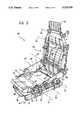
- FIG. 1is a schematic perspective view of one embodiment of the seat according to the invention.
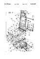
- FIG. 2is a perspective view of the frame of the seat of FIG. 1,
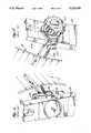
- FIG. 3is an exploded perspective view of the frame of FIG. 2,
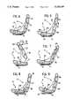
- FIGS. 4-9are schematic side views of the seat of FIG. 1, showing the various ways in which the seat can be adjusted,
- FIGS. 10 and 11are two schematic drawings which show the ergonomic principles upon which the seat according to the invention is based
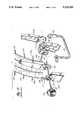
- FIG. 12is a partial schematic and enlarged vertical sectional view of a lower part of a frame of a seat according to the prior art
- FIGS. 13 and 14are schematic side views of the frame of FIG. 12 showing prior art with minimum and maximum curvature positions thereof to illustrate ergonomic principles upon which the seat according to the invention is based,
- FIG. 15is an exploded perspective view of the frame of FIG. 12 and is prior art
- FIGS. 16 and 17are prior art enlarged perspective views of the frame of FIG. 12 to illustrate details of the frame.
- a seatin FIG. 1, comprises a backrest 2 provided with a headrest 3, and a squab 4.
- the squabcomprises a frame 5, for example of pressed sheet metal, provided at the front and the rear with respective pairs of lateral pins 6, 7 which are aligned in pairs on two transverse axes 8, 9.
- the pins 6, 7are articulated respectively to two pairs of connecting-rod elements 10, 11 which are mounted for rotation about two transverse axes 12, 13 on two pairs of lugs 14, 15.
- the lugs 14, 15form part of a pressed-sheet-metal structure 16 including two guide channels 17 which are intended to be mounted for sliding on corresponding guide sections (not illustrated) fixed to the floor of the motor vehicle.
- Locking means of any known type(not illustrated), which can be released by means of a control lever 18, are associated with the structure 16 for locking it in the required position longitudinally of the motor vehicle, relative to the guide sections which are fixed to the floor of the motor vehicle.
- the channels 17 and the corresponding guide sections fixed to the floortherefore constitute the means for the adjustment of the position of the seat longitudinally of the motor vehicle.
- the structural details of the guide meansare not illustrated in detail since, as already indicated, they may be made in any known manner and do not fall within the scope of the present invention.
- connecting-rod elements 10, 11are also interconnected by means of two lateral reinforcing elements 19, also of pressed sheet metal, which have apertures for the engagement of the pins 6, 7.
- Two adjustment means of any known typeare provided in correspondence with the axes of articulation 12, 13 of the connecting-rod elements 10, 11 for adjusting the angular positions of the connecting-rod elements relative to the axes.
- a preferred solutionconsists of the use of continuous adjustment devices with meshed eccentric sets of teeth, of the type usually used for the adjustment of the inclination of the backrests of motor vehicle seats.
- the shafts 20, 21 for operating the adjustment devicesmay be provided with knobs 22, 23 for manual operation, as shown in the drawings, or may be associated with electric operating motors.
- the front of the frame 5 of the squabis also provided with a thigh-support element 24 having two rods 25 which can be housed in apertures 26 in the frame 5 and locked in various possible positions by a technique similar to that conventionally used for varying the height of the headrest of the seat.
- the frame of the backrestis generally indicated 26 and comprises a lower part 27, an upper part 28 and an intermediate part 29.
- the lower part 27 of the backrest frameis constituted by two sides (in the embodiment illustrated, the frame of the backrest is also made of pressed sheet metal, though obviously the backrest frame and the squab frame could be made, for example, of plastics material), the sides being indicated 28.
- the sides 28extend forwardly from the general plane of the backrest and at their front ends are articulated about a transverse axis 30 of the two lugs 29 forming part of the reinforcement elements 19.
- the articulation about the axis 30is achieved by means of an adjustment device made in any known manner.
- Conventional devices for the adjustment of the backrestgenerally comprise continuous adjustment devices which use meshed eccentric sets of teeth, or discontinuous adjustment devices, that is, devices which provide for a finite number of different adjustment positions defined by the engagement of two toothed sectors.
- the details of the device used for the articulation 30are not illustrated in the appended drawings, since they are of known type and do not fall within the scope of the present invention.
- the adjustment device associated with the articulation axis 30is a discontinuous device including coil springs 31 which tend to bias the backrest towards an erect position and a lever 32 which is adapted to release the toothed sectors (not illustrated) of the device to enable them to be engaged again in a different relative position.
- a deviceis provided in correspondence with the articulation axis 30, which enables the angular position of the entire backrest to be adjusted about that axis.
- the forward position of the axis 30the latter is situated substantially on the same vertical line (preferably with a tolerance ⁇ 15 mm horizontally) as the imaginary axis of articulation between the legs and the body of the seated person, and this enables the relative displacement between the back and the backrest as a result of a variation in the inclination of the backrest to be reduced to a minimum.
- the upper part 28 of the frame of the backrestis articulated to the intermediate part 29 about a transverse axis 33 by means of a further adjustment device of any known type (preferably of continuous type) provided with an operating knob 34 or associated with an electrical operating motor.
- the axis of articulation 33is situated adjacent the lordosis of the neck of the seated person so as to enable the upper part of the backrest to be adapted to the particular configuration of his cervical lordosis.
- the intermediate part 29is composed of two parts 29a and 29b mounted for sliding relative to each other vertically of the backrest, so as to enable the vertical position of the axis 33 to be varied in dependence on the particular characteristics of the seated person.
- the vertical positions of the lumbar lordosis and the lordosis of the neck, as well as their distance apart,can vary widely from one individual to another in dependence on height, weight and sex.
- FIG. 10shows schematically the profiles of a tall man and a short woman.
- the arrows A and Bindicate the lordosis of the neck and the lumbar lordosis of the man, whilst the arrows C and D indicate the lordosis of the neck and the lumbar lordosis of the woman.
- FIG. 11shows that, in order to achieve correct support for both the lumbar lordosis and the lordosis of the neck, it is necessary to provide the backrest with an upper part 28 which is articulated to the intermediate part 29, and at the same time to provide for the variation of the vertical position of the axis of articulation 33 between the parts 28 and 29.
- the vertical adjustment of the intermediate part 29is effected by means of a pair of screw actuators 35 operated by a single electric motor 36.
- Each screw 35is engaged in a nut 37 fixed to the lower part 29b of the intermediate portion 29 of the backrest frame and, at its upper end, carries a shaft 38 (connected to the screw with the interposition of a rolling bearing, not visible in the drawings) which is linked to the upper part 29a.
- the frame of the backrest of the seat according to the inventionis provided with means for varying the degree of curvature of the backrest in the region of the lumbar lordosis of the seated person.
- the lower part 29b of the intermediate portion 29 of the backrest frameis articulated to the sides 28 about a transverse axis 39 by means of a continuous adjustment device provided with a manual operating knob 40 or associated with an electric motor.
- the frame of the backrestis also provided with a resilient panel 41, for example, of the type known commercially under the trade mark "PULIMAFLEX", comprising a plurality of parallel cords intersected by a series of metal cables.
- the region of maximum curvature of the panel 41is anchored to the two sides 28 by means of helical springs.
- the upper edge of the panel 41is anchored, again by means of helical springs, to the part 29b of the frame.
- the lower edge of the panel 41is anchored to an auxiliary U-shaped element 42 mounted for rotation about the axis 39 and counter-rotated in synchronism with the part 29b of the frame by the same adjustment device 40 by the technique described in detail in the aforementioned Italian patent application.
- the mechanical characteristics of the springsare such as to ensure the correct distribution of the pressure on the surface of the body in contact with the seat. Counter-rotation of element 42 occurs in response to rotation of knob 40.
- turning knob 40 clockwisee.g., rotates, through a gear reducer, lower part 296 clockwise, thus bending the portion of panel 41 that is above fulcrum or axis 39 clockwise, causing the portion of panel 41 below axis 39 and thus element 42 to rotate counter clockwise.
- panel 41is connected to the backrest frame by means of two series of side helical springs 109 to the backrest frame.
- the backrest framecomprises sides 128 and lower part 129b.
- the lower end part 129bis articulate to the upper ends of the two sides 128, to allow for adjustment of the angular position of part 129b around transverse axis 39.
- the springs 109 which are connected to the upper part of panel 41are anchored to part 129b (see FIG. 12) while the springs which are in correspondence with the lumbar area (one spring on each side, as indicated by reference number 109a) are connected to the sides 128.
- the springs 109 which are connected to the lower part of panel 41are anchored, at their opposite ends, to U-shaped element 42 whose ends are also articulated to the two sides 128 around axis 39.
- adjustment devices 116, 117of a known type which is usually used in motor-vehicle seats to allow for continuous adjustment of the inclination of the backrest.
- the two devices 116, 117are controlled by a transverse shaft 118 having a square cross section, whose rotation can be driven by means of a knob 40.
- the inner structure of the adjustment devices 116, 117is not described in detail, since, as already indicated, it is know per se and does not fall within the scope of the present invention. Furthermore, the elimination of such details of construction from the drawings makes the latter easier to understand.
- Each of such devicesessentially comprises two plates which are reciprocally articulated and connected to each other by means of an epicyclic gear (rear reducer) which can be driven by means of the central shaft of the device and is able to cause a continuous rotation of the two plates relative to each other as a consequence of the rotation of this shaft.
- an epicyclic gearrear reducer
- device 116comprises a first plate 120 which is fixed to a bracket 121 welded to the inner side of one side 128.
- the other plate 122 of adjustment device 116forms an integral portion of one end of element 42, while the other end of such element is freely rotatable on the shaft 118.
- adjustment device 116varies the angular position of element 42 relative to sides 128.
- the adjustment device 117comprises two plates 123, 124 which are connected to one side 128 having the corresponding lower part 129b articulated to it. In this way, turning knob 40 changes the angular position of lower part 129b relative to the two sides 128.
- the arrangementis such that the action on knob 40 causes a simultaneous rotation of lower part 129b forwardly or rearwardly and element 42 rearwardly or forwardly, respectively, to vary the curvature of panel 41.
- the two helical springs 109aare anchored to the sides 128.
- one of such springsis anchored to a bracket 121 (FIG. 16) while the other spring 109a is anchored to an appendage 125 of the corresponding sides 128.
- the springs 109 which are located above springs 109aare anchored to lower part 129b, while springs 109 which are located below springs 109a are anchored to element 42.
- FIGS. 13 and 14show in cross section panel 41, in the condition of minimum and maximum curvature, respectively.
- the operation of the adjustment device 40therefore causes a variation in the curvature of the resilient panel without altering the spatial position of the region of maximum curvature of the panel. It is thus possible to adapt the curvature of the backrest to the particular configuration of the lumbar lordosis of the seated person, without varying the position of maximum curvature of the backrest longitudinally of the seat, that is, without varying the distribution of the pressures exerted by the backrest on the back of the seated person.
- the upper part 28 of the backrest frameis provided in turn with an upper frame 43 for a headrest of adjustable height, articulated to the part 28 about an axis 44 by means of a continuous adjustment device having a manual operating knob 45 or perhaps also associated with an electric operating motor.
- FIG. 4shows a schematic side view of the seat according to the invention, with its various axes of articulation.
- the arrowsrefer to the fact that the front thigh-support 4 and the vertical position of the articulation axis 33 can be adjusted.
- FIG. 6shows that it is also possible to provide a device in correspondence with the axis 30, for enabling the seat to be tilted forwards for use in two-door motor cars to enable access to the rear seats.
- the arrows in FIG. 7refer to the fact that the curvature of the backrest can be adjusted in the lumbar region and the angular position of the upper part of the backrest can be adjusted to achieve correct support in correspondence with the lordosis of the neck.
- FIGS. 8 and 9relate to the various possible adjustments of the position of the squab of the seat.
- any technologymay be used to produce the frame of the squab and the frame of the backrest, as well as their padding.
- paddingprovided with a subframe which can rapidly be connected to and released from the relative support frame is used.
Landscapes
- Engineering & Computer Science (AREA)
- Aviation & Aerospace Engineering (AREA)
- Transportation (AREA)
- Mechanical Engineering (AREA)
- Seats For Vehicles (AREA)
- Chair Legs, Seat Parts, And Backrests (AREA)
- Percussion Or Vibration Massage (AREA)
- Vehicle Waterproofing, Decoration, And Sanitation Devices (AREA)
Abstract
Description
Claims (6)
Applications Claiming Priority (2)
| Application Number | Priority Date | Filing Date | Title |
|---|---|---|---|
| IT67707A/88 | 1988-07-25 | ||
| IT67707/88AIT1223725B (en) | 1988-07-25 | 1988-07-25 | VEHICLE SEAT |
Publications (1)
| Publication Number | Publication Date |
|---|---|
| US5120109Atrue US5120109A (en) | 1992-06-09 |
Family
ID=11304670
Family Applications (1)
| Application Number | Title | Priority Date | Filing Date |
|---|---|---|---|
| US07/383,140Expired - LifetimeUS5120109A (en) | 1988-07-25 | 1989-07-20 | Motor vehicle seat |
Country Status (7)
| Country | Link |
|---|---|
| US (1) | US5120109A (en) |
| EP (1) | EP0353210B1 (en) |
| JP (1) | JPH0274429A (en) |
| AT (1) | ATE77993T1 (en) |
| DE (1) | DE68902020T2 (en) |
| ES (1) | ES2033137T3 (en) |
| IT (1) | IT1223725B (en) |
Cited By (85)
| Publication number | Priority date | Publication date | Assignee | Title |
|---|---|---|---|---|
| US5385531A (en)* | 1992-07-08 | 1995-01-31 | Eurokeyton S.A. | Massage robot for relaxation armchair |
| US5389062A (en)* | 1992-10-05 | 1995-02-14 | Mitchum, Jr.; John T. | Intercourse-facilitating therapeutic furniture |
| US5486036A (en)* | 1992-09-18 | 1996-01-23 | Aisin Seiki Kabushiki Kaisha | Seat-height adjusting device |
| US5651584A (en)* | 1995-04-24 | 1997-07-29 | L & P Property Management Company | Lumbar support structure for automotive vehicle |
| US5704689A (en)* | 1995-02-15 | 1998-01-06 | Kim; Moung Sook | Chair having separable back |
| US5713633A (en)* | 1996-07-15 | 1998-02-03 | Lu; Kuo-Ching | Backrest assembly with chamber for articles |
| WO1998009554A1 (en)* | 1996-09-09 | 1998-03-12 | Ab Volvo | Back support structure for a seat |
| US5871258A (en)* | 1997-10-24 | 1999-02-16 | Steelcase Inc. | Chair with novel seat construction |
| WO2000009358A1 (en)* | 1998-08-13 | 2000-02-24 | Ab Volvo | Adjustable vehicle seat |
| US6079785A (en)* | 1999-01-12 | 2000-06-27 | Steelcase Development Inc. | Chair having adjustable lumbar support |
| US6109693A (en)* | 1996-11-07 | 2000-08-29 | Bauer; Heinz | Motor vehicle seat with a seat support with a device for the adjustment of the seat depth |
| DE19930942A1 (en)* | 1999-07-05 | 2001-01-18 | Faure Bertrand Sitztech Gmbh | Backrest for motor vehicle seat has top backrest section and head restraint holder height-adjustable relative to lower backrest section for individual adjustment |
| US6273506B1 (en) | 1995-06-07 | 2001-08-14 | Herman Miller, Inc. | Chair with an adjustable seat |
| DE10051455A1 (en)* | 2000-10-17 | 2002-04-25 | Faurecia Autositze Gmbh & Co | Front seat for two-door car is mounted on rails, allowing its position to be adjusted, fastened to chassis by pivot at front end and lock at rear which can be released in event of a crash, improving exit space for rear seat passengers |
| US6478379B1 (en) | 2000-06-07 | 2002-11-12 | Center For Design Research And Development N.V. | Chair |
| US6530622B1 (en)* | 2001-03-16 | 2003-03-11 | Johnson Controls Technology Company | Biomechanical vehicle seat |
| US20040080198A1 (en)* | 2002-10-25 | 2004-04-29 | Richard Frank | Seat bolster system apparatus and method |
| DE10261899A1 (en)* | 2002-12-23 | 2004-07-01 | Volkswagen Ag | Massaging body parts of seated person involves curved element carrying out cyclical movements of defined duration in at least two spatial directions from second position, returning to initial position |
| US20040195895A1 (en)* | 2003-02-25 | 2004-10-07 | Stanzwerk Wetter Sichelschmidt Gmbh & Co. Kg | Seat back with adjustable headrest |
| US20050029849A1 (en)* | 2003-06-23 | 2005-02-10 | Goetz Mark W. | Tilt chair |
| US20050052060A1 (en)* | 2002-08-07 | 2005-03-10 | Klaus Beloch | Motor vehicle seat system, control arrangement, actuating arrangement, and process for control of a lumbar adjustment device of a motor vehicle seat |
| DE102004005705A1 (en)* | 2004-02-05 | 2005-09-01 | Isringhausen Gmbh & Co Kg | Automotive seat back rake adjustment button or lever is incorporated within headrest |
| US20050275263A1 (en)* | 2004-06-10 | 2005-12-15 | Norman Christopher J | Back construction with flexible lumbar |
| US20050275264A1 (en)* | 2004-06-10 | 2005-12-15 | Norman Christopher J | Back construction with flexible lumbar |
| US20060152062A1 (en)* | 2004-12-20 | 2006-07-13 | Baultar I.D. Inc. | Adjustable ergonomic back for a seat |
| DE102005001960A1 (en)* | 2005-01-15 | 2006-07-20 | Daimlerchrysler Ag | vehicle seat |
| US20070057550A1 (en)* | 2005-03-01 | 2007-03-15 | Beyer Pete J | Chair back with lumbar and pelvic supports |
| US20070069563A1 (en)* | 2003-06-06 | 2007-03-29 | Mario Herzog | Apparatus for supporting the body of a person |
| US20070252421A1 (en)* | 2004-06-09 | 2007-11-01 | Otto Zapf | Vehicle Seat |
| US20080012414A1 (en)* | 2005-01-14 | 2008-01-17 | Eckhart Dewert | Armchair |
| US20080231100A1 (en)* | 2007-03-19 | 2008-09-25 | Pbrd Innovations | Reclining chair and chassis, frame and kit therefor |
| US20080252128A1 (en)* | 2007-04-06 | 2008-10-16 | Toyota Boshoku Kabushiki Kaisha | Vehicle seats |
| US20090044820A1 (en)* | 2007-08-19 | 2009-02-19 | Anastasia Soare | Stencils and gauging device for aesthetically pleasing eyebrow shaping |
| US20100072799A1 (en)* | 2008-05-26 | 2010-03-25 | Peterson Gordon J | Conforming back for a seating unit |
| US20100102605A1 (en)* | 2007-07-05 | 2010-04-29 | Aisin Seiki Kabushiki Kaisha | Vehicle seat device |
| US7922248B2 (en) | 2007-01-29 | 2011-04-12 | Herman Miller, Inc. | Seating structure and methods for the use thereof |
| CN102381216A (en)* | 2010-08-25 | 2012-03-21 | 株式会社电装 | Seat device having a function of retaining person's seated position |
| US20120086256A1 (en)* | 2010-10-12 | 2012-04-12 | La-Z-Boy Incorporated | Furniture member powered headrest rotation and release system |
| USD696545S1 (en) | 2013-07-30 | 2013-12-31 | Steelcase, Inc. | Rear surface of a chair back |
| US20140203603A1 (en)* | 2013-01-24 | 2014-07-24 | Ford Global Technologies, Llc | Flexible seatback system |
| US20140265504A1 (en)* | 2011-10-05 | 2014-09-18 | Nhk Spring Co., Ltd. | Vehicle seat |
| US20150258919A1 (en)* | 2007-12-12 | 2015-09-17 | Ts Tech Co., Ltd. | Center-foldable seat back, seat with the same, and method of manufacturing center-foldable seat back |
| US20150360592A1 (en)* | 2014-06-13 | 2015-12-17 | Lear Corporation | Seat assembly having a tiltable front cushion module |
| US20160075260A1 (en)* | 2014-09-17 | 2016-03-17 | Stelia Aerospace | Multiple-position seat for driving operator |
| US20160121761A1 (en)* | 2014-11-04 | 2016-05-05 | Honda Motor Co., Ltd | Seat for vehicles |
| US9352675B2 (en) | 2011-09-21 | 2016-05-31 | Herman Miller, Inc. | Bi-level headrest, body support structure and method of supporting a user's cranium |
| US9580174B2 (en)* | 2011-05-26 | 2017-02-28 | Optimares S.P.A. | Seating unit for transportation means, in particular for aircrafts |
| US9604560B1 (en) | 2015-11-13 | 2017-03-28 | Kongsberg Automotive, Inc. | Assembly for adjusting a lumbar region of a seat |
| US9649962B2 (en) | 2013-01-24 | 2017-05-16 | Ford Global Technologies, Llc | Independent cushion extension and thigh support |
| US20170158084A1 (en)* | 2015-12-04 | 2017-06-08 | Ford Global Technologies, Llc | Anthropomorphic pivotable upper seatback support |
| US9707873B2 (en) | 2013-01-24 | 2017-07-18 | Ford Global Technologies, Llc | Flexible seatback system |
| US9802512B1 (en) | 2016-04-12 | 2017-10-31 | Ford Global Technologies, Llc | Torsion spring bushing |
| US9834166B1 (en) | 2016-06-07 | 2017-12-05 | Ford Global Technologies, Llc | Side airbag energy management system |
| US9845029B1 (en) | 2016-06-06 | 2017-12-19 | Ford Global Technologies, Llc | Passive conformal seat with hybrid air/liquid cells |
| US9849856B1 (en) | 2016-06-07 | 2017-12-26 | Ford Global Technologies, Llc | Side airbag energy management system |
| US9849817B2 (en) | 2016-03-16 | 2017-12-26 | Ford Global Technologies, Llc | Composite seat structure |
| US9889773B2 (en) | 2016-04-04 | 2018-02-13 | Ford Global Technologies, Llc | Anthropomorphic upper seatback |
| US20180043808A1 (en)* | 2016-08-12 | 2018-02-15 | Lear Corporation | Integrated seat back support member for seat assemblies |
| US9914378B1 (en) | 2016-12-16 | 2018-03-13 | Ford Global Technologies, Llc | Decorative and functional upper seatback closeout assembly |
| US9994135B2 (en) | 2016-03-30 | 2018-06-12 | Ford Global Technologies, Llc | Independent cushion thigh support |
| US10035442B2 (en)* | 2016-01-25 | 2018-07-31 | Ford Global Technologies, Llc | Adjustable upper seatback module |
| US10046683B2 (en) | 2014-01-23 | 2018-08-14 | Ford Global Technologies, Llc | Suspension seat back and cushion system having an inner suspension panel |
| US10046682B2 (en) | 2015-08-03 | 2018-08-14 | Ford Global Technologies, Llc | Back cushion module for a vehicle seating assembly |
| US10065546B2 (en) | 2014-04-02 | 2018-09-04 | Ford Global Technologies, Llc | Vehicle seating assembly with manual independent thigh supports |
| US10166894B2 (en) | 2016-06-09 | 2019-01-01 | Ford Global Technologies, Llc | Seatback comfort carrier |
| US10166895B2 (en) | 2016-06-09 | 2019-01-01 | Ford Global Technologies, Llc | Seatback comfort carrier |
| US10220737B2 (en) | 2016-04-01 | 2019-03-05 | Ford Global Technologies, Llc | Kinematic back panel |
| US10239431B2 (en) | 2016-09-02 | 2019-03-26 | Ford Global Technologies, Llc | Cross-tube attachment hook features for modular assembly and support |
| US10279714B2 (en) | 2016-08-26 | 2019-05-07 | Ford Global Technologies, Llc | Seating assembly with climate control features |
| US10286818B2 (en) | 2016-03-16 | 2019-05-14 | Ford Global Technologies, Llc | Dual suspension seating assembly |
| US10286824B2 (en) | 2016-08-24 | 2019-05-14 | Ford Global Technologies, Llc | Spreader plate load distribution |
| US10299602B2 (en)* | 2017-03-22 | 2019-05-28 | Yao-Chuan Wu | Chair |
| US10369905B2 (en) | 2014-10-03 | 2019-08-06 | Ford Global Technologies, Llc | Tuned flexible support member and flexible suspension features for comfort carriers |
| USD856020S1 (en)* | 2017-06-22 | 2019-08-13 | Hessam Ghahramanian | Racing simulator cockpit |
| US10377279B2 (en) | 2016-06-09 | 2019-08-13 | Ford Global Technologies, Llc | Integrated decking arm support feature |
| US10391910B2 (en) | 2016-09-02 | 2019-08-27 | Ford Global Technologies, Llc | Modular assembly cross-tube attachment tab designs and functions |
| US10427569B2 (en) | 2015-01-26 | 2019-10-01 | Kongsberg Automotive, Inc. | Adjustment mechanism for a seat |
| US20200079263A1 (en)* | 2018-09-12 | 2020-03-12 | Rockwell Collins, Inc. | Multi-Stage Seatback Extension System |
| US10596936B2 (en) | 2017-05-04 | 2020-03-24 | Ford Global Technologies, Llc | Self-retaining elastic strap for vent blower attachment to a back carrier |
| US10717534B2 (en)* | 2018-12-17 | 2020-07-21 | Goodrich Corporation | Extendable split headrest |
| US10906434B2 (en)* | 2018-11-14 | 2021-02-02 | Wonderland Switzerland Ag | Child safety seat |
| US20210245634A1 (en)* | 2018-06-13 | 2021-08-12 | Brose Fahrzeugteile SE & Co. Kommanditgesellschaft, Coburg | Backrest for a vehicle seat, and backrest head module |
| US11634048B2 (en)* | 2019-01-15 | 2023-04-25 | Nhk Spring Co., Ltd. | Vehicle seat |
| US20240122345A1 (en)* | 2022-10-13 | 2024-04-18 | Hidden Lake 822, Llc | Drive motor-linear actuator system for powered lift or powered reclining chairs |
| US20240342025A1 (en)* | 2022-02-28 | 2024-10-17 | Board Of Trustees Of Michigan State University | Articulating Chair |
Families Citing this family (32)
| Publication number | Priority date | Publication date | Assignee | Title |
|---|---|---|---|---|
| JP2532932Y2 (en)* | 1990-03-27 | 1997-04-16 | 富士重工業株式会社 | Car seat |
| ATE95471T1 (en)* | 1990-05-22 | 1993-10-15 | Sepi Spa | CAR SEAT. |
| DE4128160C5 (en)* | 1991-08-24 | 2009-04-16 | Robert Bosch Gmbh | Device for adjusting the course of the backrest to the sitting position of a person |
| JP2565012Y2 (en)* | 1991-10-29 | 1998-03-11 | 天龍工業株式会社 | Vehicle seat |
| DE4228637A1 (en)* | 1992-08-28 | 1994-03-03 | Roeder Soehne Sitzmoebelfab | Chair with a height-adjustable backrest |
| DE19512012C2 (en)* | 1995-03-31 | 1998-05-07 | Brose Fahrzeugteile | Adjustable, cross-split backrest for a vehicle seat |
| FR2736312B1 (en)* | 1995-07-03 | 1997-09-19 | Faure Bertrand Equipements Sa | BACKREST FOR VEHICLE SEAT AND SEAT COMPRISING SUCH A BACKREST |
| DE19726800C2 (en)* | 1997-06-24 | 2002-12-05 | Faurecia Autositze Gmbh & Co | Motor vehicle backrest with an adjustment device for pivoting the backrest head |
| FR2777518B1 (en)* | 1998-04-17 | 2000-06-16 | Faure Bertrand Equipements Sa | MOTOR VEHICLE SEAT BACKREST |
| FR2799165B1 (en)* | 1999-09-30 | 2001-11-23 | Faure Bertrand Equipements Sa | MOTOR VEHICLE SEAT HAVING AN ADJUSTABLE SEAT IN POSITION |
| US6817673B2 (en) | 2002-04-17 | 2004-11-16 | Lear Corporation | Vehicle seat assembly |
| DE10243796B4 (en)* | 2002-09-17 | 2004-07-29 | Bertrandt Ingenieurbüro GmbH | vehicle seat |
| US6945601B1 (en)* | 2003-12-23 | 2005-09-20 | Yao-Chuan Wu | Multi-stage backrest assembly |
| DE602005010686D1 (en)* | 2004-04-30 | 2008-12-11 | L & P Property Management Co | INTEGRATED LORENDER AND HEAD SUPPORT SYSTEM |
| US7192087B2 (en) | 2004-09-23 | 2007-03-20 | Lear Corporation | Adjustable seat cushion thigh support system and method |
| DE102006045387B4 (en)* | 2006-03-24 | 2011-12-15 | Audi Ag | Backrest for motor vehicle seat, has backrest head module inserted in backrest frame, where backrest head module is retained pivotably about hinge axis that runs between lateral pieces in region of frame upper part |
| GB0609315D0 (en) | 2006-05-11 | 2006-06-21 | Technicon Internat Man Service | Improved seat |
| DE202007010292U1 (en) | 2006-09-26 | 2008-02-21 | Audi Ag | Seat back for a motor vehicle and motor vehicle seat |
| DE102007034462B4 (en) | 2007-07-20 | 2012-10-25 | Brose Fahrzeugteile Gmbh & Co. Kommanditgesellschaft, Coburg | Seat back for a motor vehicle and motor vehicle seat |
| US8567842B2 (en)* | 2010-08-05 | 2013-10-29 | Ford Global Technologies, Llc | Transverse sliding/accommodation easy entry seat |
| US9592914B2 (en) | 2011-10-07 | 2017-03-14 | Bombardier Inc. | Aircraft seat |
| US9714095B2 (en) | 2011-10-07 | 2017-07-25 | Bombardier Inc. | Aircraft seat |
| US9714862B2 (en) | 2011-10-07 | 2017-07-25 | Bombardier Inc. | Aircraft seat |
| UA99798C2 (en)* | 2011-11-18 | 2012-09-25 | Владимир Гаврилович Шишкин | Antitheft device adjusted for vehicle seat |
| CN103129417A (en)* | 2011-11-22 | 2013-06-05 | 张兴钿 | Personalized seat |
| CA2962585C (en) | 2014-09-25 | 2022-07-26 | Bombardier Inc. | Aircraft seat |
| GB2530556A (en)* | 2014-09-26 | 2016-03-30 | Bombardier Inc | Aircraft seat |
| DE102016218014A1 (en)* | 2015-11-27 | 2017-06-01 | Johnson Controls Metals and Mechanisms GmbH & Co. KG | Seat depth adjuster |
| US10543923B2 (en)* | 2017-11-28 | 2020-01-28 | Ami Industries, Inc. | Seat backrest |
| DE102022119627A1 (en) | 2022-05-16 | 2023-11-16 | Adient Us Llc | VEHICLE SEAT |
| CN119137012A (en) | 2022-05-16 | 2024-12-13 | 安道拓美国有限责任公司 | Vehicle seats |
| DE102022120164A1 (en) | 2022-06-13 | 2023-12-14 | Adient Us Llc | LOWER LEG SUPPORT DEVICE FOR A VEHICLE SEAT AND VEHICLE SEAT |
Citations (10)
| Publication number | Priority date | Publication date | Assignee | Title |
|---|---|---|---|---|
| US2646839A (en)* | 1948-08-06 | 1953-07-28 | Autocar Company | Adjustable seat structure |
| US2924265A (en)* | 1955-04-14 | 1960-02-09 | Gen Motors Corp | Vehicle seat |
| US3724895A (en)* | 1970-10-31 | 1973-04-03 | Daimler Benz Ag | Mechanism for adjusting the height of seats, especially of motor vehicles |
| US4155593A (en)* | 1978-03-20 | 1979-05-22 | Milsco Manufacturing Company | Vehicle seat having seat rake adjustment means |
| US4156544A (en)* | 1978-03-20 | 1979-05-29 | Milsco Manufacturing Company | Vehicle seat having lumbar support adjustment means |
| US4387874A (en)* | 1979-11-14 | 1983-06-14 | Societe Industrielle Bertrand Faure | Adjustable vehicle seats and their adjustment mechanisms |
| US4641884A (en)* | 1985-02-21 | 1987-02-10 | Honda Giken Kogyo Kabushiki Kaisha | Seat for vehicles |
| DE3634500A1 (en)* | 1986-02-10 | 1987-08-20 | Wilfried Prof Dr Me Diebschlag | Seat, in particular car seat |
| US4717203A (en)* | 1985-09-12 | 1988-01-05 | Grammer Sitzsysteme Gmbh | Seat having an adjustable seat portion |
| US4834455A (en)* | 1988-07-14 | 1989-05-30 | Proctor Joy E | Orthopedic vehicle seat |
Family Cites Families (5)
| Publication number | Priority date | Publication date | Assignee | Title |
|---|---|---|---|---|
| JPS5495421A (en)* | 1978-01-13 | 1979-07-27 | Nissan Motor Co Ltd | Seat for vehicle |
| AU556056B2 (en)* | 1984-10-11 | 1986-10-23 | Mitsubishi Motors Corp. | Horizontally split seat back |
| DE3532295A1 (en)* | 1985-09-11 | 1987-03-19 | Schmitz & Co | Actuation arrangement for fitting elements on the seats of motor vehicles |
| DE3604187A1 (en)* | 1986-02-10 | 1986-10-09 | Wilfried Prof. Dr.med. Dr.-Ing. Diebschlag | Seat, in particular car seat |
| DE3704489A1 (en)* | 1987-02-13 | 1988-08-25 | Daimler Benz Ag | MOTOR CAR SEAT |
- 1988
- 1988-07-25ITIT67707/88Apatent/IT1223725B/enactive
- 1989
- 1989-07-20USUS07/383,140patent/US5120109A/ennot_activeExpired - Lifetime
- 1989-07-24JPJP1192420Apatent/JPH0274429A/enactivePending
- 1989-07-25ATAT89830348Tpatent/ATE77993T1/enactive
- 1989-07-25DEDE8989830348Tpatent/DE68902020T2/ennot_activeExpired - Lifetime
- 1989-07-25EPEP89830348Apatent/EP0353210B1/ennot_activeExpired - Lifetime
- 1989-07-25ESES198989830348Tpatent/ES2033137T3/ennot_activeExpired - Lifetime
Patent Citations (10)
| Publication number | Priority date | Publication date | Assignee | Title |
|---|---|---|---|---|
| US2646839A (en)* | 1948-08-06 | 1953-07-28 | Autocar Company | Adjustable seat structure |
| US2924265A (en)* | 1955-04-14 | 1960-02-09 | Gen Motors Corp | Vehicle seat |
| US3724895A (en)* | 1970-10-31 | 1973-04-03 | Daimler Benz Ag | Mechanism for adjusting the height of seats, especially of motor vehicles |
| US4155593A (en)* | 1978-03-20 | 1979-05-22 | Milsco Manufacturing Company | Vehicle seat having seat rake adjustment means |
| US4156544A (en)* | 1978-03-20 | 1979-05-29 | Milsco Manufacturing Company | Vehicle seat having lumbar support adjustment means |
| US4387874A (en)* | 1979-11-14 | 1983-06-14 | Societe Industrielle Bertrand Faure | Adjustable vehicle seats and their adjustment mechanisms |
| US4641884A (en)* | 1985-02-21 | 1987-02-10 | Honda Giken Kogyo Kabushiki Kaisha | Seat for vehicles |
| US4717203A (en)* | 1985-09-12 | 1988-01-05 | Grammer Sitzsysteme Gmbh | Seat having an adjustable seat portion |
| DE3634500A1 (en)* | 1986-02-10 | 1987-08-20 | Wilfried Prof Dr Me Diebschlag | Seat, in particular car seat |
| US4834455A (en)* | 1988-07-14 | 1989-05-30 | Proctor Joy E | Orthopedic vehicle seat |
Cited By (156)
| Publication number | Priority date | Publication date | Assignee | Title |
|---|---|---|---|---|
| US5385531A (en)* | 1992-07-08 | 1995-01-31 | Eurokeyton S.A. | Massage robot for relaxation armchair |
| US5486036A (en)* | 1992-09-18 | 1996-01-23 | Aisin Seiki Kabushiki Kaisha | Seat-height adjusting device |
| US5389062A (en)* | 1992-10-05 | 1995-02-14 | Mitchum, Jr.; John T. | Intercourse-facilitating therapeutic furniture |
| US5704689A (en)* | 1995-02-15 | 1998-01-06 | Kim; Moung Sook | Chair having separable back |
| US5651584A (en)* | 1995-04-24 | 1997-07-29 | L & P Property Management Company | Lumbar support structure for automotive vehicle |
| US6513222B2 (en) | 1995-06-07 | 2003-02-04 | Herman Miller, Inc. | Method for adjusting a seat |
| US6273506B1 (en) | 1995-06-07 | 2001-08-14 | Herman Miller, Inc. | Chair with an adjustable seat |
| US5713633A (en)* | 1996-07-15 | 1998-02-03 | Lu; Kuo-Ching | Backrest assembly with chamber for articles |
| WO1998009554A1 (en)* | 1996-09-09 | 1998-03-12 | Ab Volvo | Back support structure for a seat |
| US6309018B1 (en) | 1996-09-09 | 2001-10-30 | Volvo Car Corporation | Back support structure for a seat |
| US6109693A (en)* | 1996-11-07 | 2000-08-29 | Bauer; Heinz | Motor vehicle seat with a seat support with a device for the adjustment of the seat depth |
| US6460928B2 (en) | 1997-10-24 | 2002-10-08 | Steelcase Development Corporation | Seating unit including novel back construction |
| US20050127729A1 (en)* | 1997-10-24 | 2005-06-16 | Knoblock Glenn A. | Back construction for seating unit having spring bias |
| US5871258A (en)* | 1997-10-24 | 1999-02-16 | Steelcase Inc. | Chair with novel seat construction |
| US7040709B2 (en) | 1997-10-24 | 2006-05-09 | Steelcase Development Corporation | Back construction for seating unit having inverted U-shaped frame |
| US6991291B2 (en) | 1997-10-24 | 2006-01-31 | Steelcase Development Corporation | Back construction for seating unit having spring bias |
| US6349992B1 (en) | 1997-10-24 | 2002-02-26 | Steelcase Development Corporation | Seating unit including novel back construction |
| US6367877B1 (en) | 1997-10-24 | 2002-04-09 | Steelcase Development Corporation | Back for seating unit |
| US7131700B2 (en) | 1997-10-24 | 2006-11-07 | Steelcase Development Corporation | Back construction for seating unit |
| US6394545B2 (en) | 1997-10-24 | 2002-05-28 | Steelcase Development Corporation | Back for seating unit |
| US6394546B1 (en) | 1997-10-24 | 2002-05-28 | Steelcase Development Corporation | Lumbar device |
| US6394548B1 (en) | 1997-10-24 | 2002-05-28 | Steelcase Development Corporation | Seating unit with novel seat construction |
| US7114777B2 (en) | 1997-10-24 | 2006-10-03 | Steelcase Development Corporation | Chair having reclineable back and movable seat |
| US20050231013A1 (en)* | 1997-10-24 | 2005-10-20 | Knoblock Glenn A | Back construction for seating unit |
| US20070024098A1 (en)* | 1997-10-24 | 2007-02-01 | Knoblock Glenn A | Back construction for seating unit |
| US5975634A (en)* | 1997-10-24 | 1999-11-02 | Steelcase Development Inc. | Chair including novel back construction |
| US20050179292A1 (en)* | 1997-10-24 | 2005-08-18 | Knoblock Glenn A. | Back construction for seating unit having inverted U-shaped frame |
| US6905171B2 (en) | 1997-10-24 | 2005-06-14 | Steelcase Development Corporation | Seating unit including novel back construction |
| US20050046254A1 (en)* | 1997-10-24 | 2005-03-03 | Knoblock Glenn A. | Chair having reclineable back and movable seat |
| US6749261B2 (en) | 1997-10-24 | 2004-06-15 | Steelcase Development Corporation | Seating unit including novel back construction |
| US7427105B2 (en) | 1997-10-24 | 2008-09-23 | Steelcase Inc. | Back construction for seating unit |
| WO2000009358A1 (en)* | 1998-08-13 | 2000-02-24 | Ab Volvo | Adjustable vehicle seat |
| US6601918B2 (en)* | 1998-08-13 | 2003-08-05 | Volvo Personvagnar Ab | Adjustable vehicle seat |
| US6079785A (en)* | 1999-01-12 | 2000-06-27 | Steelcase Development Inc. | Chair having adjustable lumbar support |
| DE19930942C2 (en)* | 1999-07-05 | 2001-09-20 | Faurecia Autositze Gmbh & Co | Backrest of a motor vehicle seat |
| DE19930942A1 (en)* | 1999-07-05 | 2001-01-18 | Faure Bertrand Sitztech Gmbh | Backrest for motor vehicle seat has top backrest section and head restraint holder height-adjustable relative to lower backrest section for individual adjustment |
| CN100377679C (en)* | 2000-06-07 | 2008-04-02 | 设计研究和发展中心股份有限公司 | Chair (Ref. TM. chair) |
| US6478379B1 (en) | 2000-06-07 | 2002-11-12 | Center For Design Research And Development N.V. | Chair |
| DE10051455A1 (en)* | 2000-10-17 | 2002-04-25 | Faurecia Autositze Gmbh & Co | Front seat for two-door car is mounted on rails, allowing its position to be adjusted, fastened to chassis by pivot at front end and lock at rear which can be released in event of a crash, improving exit space for rear seat passengers |
| DE10051455C2 (en)* | 2000-10-17 | 2003-01-23 | Faurecia Autositze Gmbh & Co | Front seat for a two-door motor vehicle |
| DE10051455C5 (en)* | 2000-10-17 | 2006-12-14 | Faurecia Autositze Gmbh & Co. Kg | Front seat for a two-door motor vehicle |
| US6530622B1 (en)* | 2001-03-16 | 2003-03-11 | Johnson Controls Technology Company | Biomechanical vehicle seat |
| US20050052060A1 (en)* | 2002-08-07 | 2005-03-10 | Klaus Beloch | Motor vehicle seat system, control arrangement, actuating arrangement, and process for control of a lumbar adjustment device of a motor vehicle seat |
| US7172247B2 (en) | 2002-08-07 | 2007-02-06 | Brose Fahrzeugteile Gmbh & Co Kg, Coburg | Motor vehicle seat system, control arrangement, actuating arrangement, and process for control of a lumbar adjustment device of a motor vehicle seat |
| US20040080198A1 (en)* | 2002-10-25 | 2004-04-29 | Richard Frank | Seat bolster system apparatus and method |
| US7125077B2 (en)* | 2002-10-25 | 2006-10-24 | L&P Property Management Company | Seat bolster adjustment apparatus and method |
| DE10261899A1 (en)* | 2002-12-23 | 2004-07-01 | Volkswagen Ag | Massaging body parts of seated person involves curved element carrying out cyclical movements of defined duration in at least two spatial directions from second position, returning to initial position |
| DE10261899B4 (en)* | 2002-12-23 | 2015-11-26 | Volkswagen Ag | Method and system for massage of body parts with a lordosis |
| US20040195895A1 (en)* | 2003-02-25 | 2004-10-07 | Stanzwerk Wetter Sichelschmidt Gmbh & Co. Kg | Seat back with adjustable headrest |
| US7097246B2 (en)* | 2003-02-25 | 2006-08-29 | Stanzwerk Wetter Sichelschmidt Gmbh & Co. Kg | Seat back with adjustable headrest |
| US20070069563A1 (en)* | 2003-06-06 | 2007-03-29 | Mario Herzog | Apparatus for supporting the body of a person |
| US20050029849A1 (en)* | 2003-06-23 | 2005-02-10 | Goetz Mark W. | Tilt chair |
| US7207629B2 (en) | 2003-06-23 | 2007-04-24 | Herman Miller, Inc. | Tilt chair |
| DE102004005705A1 (en)* | 2004-02-05 | 2005-09-01 | Isringhausen Gmbh & Co Kg | Automotive seat back rake adjustment button or lever is incorporated within headrest |
| DE102004005705B4 (en)* | 2004-02-05 | 2011-06-16 | Isringhausen Gmbh & Co Kg | Backrest for a vehicle seat and vehicle seat |
| US20070252421A1 (en)* | 2004-06-09 | 2007-11-01 | Otto Zapf | Vehicle Seat |
| US7445288B2 (en)* | 2004-06-09 | 2008-11-04 | Otto Zapf | Vehicle seat |
| US20050275263A1 (en)* | 2004-06-10 | 2005-12-15 | Norman Christopher J | Back construction with flexible lumbar |
| US7458637B2 (en) | 2004-06-10 | 2008-12-02 | Steelcase Inc. | Back construction with flexible lumbar |
| US7237841B2 (en) | 2004-06-10 | 2007-07-03 | Steelcase Development Corporation | Back construction with flexible lumbar |
| US20050275264A1 (en)* | 2004-06-10 | 2005-12-15 | Norman Christopher J | Back construction with flexible lumbar |
| US20060152062A1 (en)* | 2004-12-20 | 2006-07-13 | Baultar I.D. Inc. | Adjustable ergonomic back for a seat |
| US7559607B2 (en)* | 2004-12-20 | 2009-07-14 | Baultar I.D. Inc. | Adjustable ergonomic back for a seat |
| US20080012414A1 (en)* | 2005-01-14 | 2008-01-17 | Eckhart Dewert | Armchair |
| US20090102264A1 (en)* | 2005-01-15 | 2009-04-23 | Daimlerchrysler Ag | Vehicle Seat |
| DE102005001960A1 (en)* | 2005-01-15 | 2006-07-20 | Daimlerchrysler Ag | vehicle seat |
| US20070057550A1 (en)* | 2005-03-01 | 2007-03-15 | Beyer Pete J | Chair back with lumbar and pelvic supports |
| US8845024B2 (en) | 2005-03-01 | 2014-09-30 | Haworth, Inc. | Chair back with lumbar and pelvic supports |
| US7347495B2 (en) | 2005-03-01 | 2008-03-25 | Haworth, Inc. | Chair back with lumbar and pelvic supports |
| US7484802B2 (en) | 2005-03-01 | 2009-02-03 | Haworth, Inc. | Chair back with lumbar and pelvic supports |
| US9538849B2 (en) | 2005-03-01 | 2017-01-10 | Haworth, Inc. | Chair back with lumbar and pelvic supports |
| US20090256407A1 (en)* | 2005-03-01 | 2009-10-15 | Haworth, Inc. | Chair back with lumbar and pelvic supports |
| US8313143B2 (en) | 2005-03-01 | 2012-11-20 | Haworth, Inc. | Chair back with lumbar and pelvic supports |
| US7922248B2 (en) | 2007-01-29 | 2011-04-12 | Herman Miller, Inc. | Seating structure and methods for the use thereof |
| US8419133B2 (en) | 2007-01-29 | 2013-04-16 | Herman Miller, Inc. | Seating structure with independently adjustable back |
| US8210611B2 (en) | 2007-01-29 | 2012-07-03 | Herman Miller, Inc. | Seating structure and methods for the use thereof |
| US7802846B2 (en)* | 2007-03-19 | 2010-09-28 | Pierre Bellefleur | Reclining chair and chassis, frame and kit therefor |
| US20080231100A1 (en)* | 2007-03-19 | 2008-09-25 | Pbrd Innovations | Reclining chair and chassis, frame and kit therefor |
| US7686394B2 (en)* | 2007-04-06 | 2010-03-30 | Toyota Boshoku Kabushiki Kaisha | Vehicle seats |
| US20080252128A1 (en)* | 2007-04-06 | 2008-10-16 | Toyota Boshoku Kabushiki Kaisha | Vehicle seats |
| US20100102605A1 (en)* | 2007-07-05 | 2010-04-29 | Aisin Seiki Kabushiki Kaisha | Vehicle seat device |
| US7845729B2 (en)* | 2007-07-05 | 2010-12-07 | Aisin Seiki Kabushiki Kaisha | Vehicle seat device |
| US20090044820A1 (en)* | 2007-08-19 | 2009-02-19 | Anastasia Soare | Stencils and gauging device for aesthetically pleasing eyebrow shaping |
| US20150258919A1 (en)* | 2007-12-12 | 2015-09-17 | Ts Tech Co., Ltd. | Center-foldable seat back, seat with the same, and method of manufacturing center-foldable seat back |
| US10791842B2 (en) | 2008-05-26 | 2020-10-06 | Steelcase Inc. | Conforming back for a seating unit |
| US20100072799A1 (en)* | 2008-05-26 | 2010-03-25 | Peterson Gordon J | Conforming back for a seating unit |
| USD696055S1 (en) | 2008-05-26 | 2013-12-24 | Steelcase, Inc. | Chair back |
| US9648956B2 (en) | 2008-05-26 | 2017-05-16 | Steelcase, Inc. | Conforming back for a seating unit |
| USD696546S1 (en) | 2008-05-26 | 2013-12-31 | Steelcase, Inc. | Chair back |
| US8876209B2 (en) | 2008-05-26 | 2014-11-04 | Steelcase Inc. | Conforming back for a seating unit |
| CN102381216A (en)* | 2010-08-25 | 2012-03-21 | 株式会社电装 | Seat device having a function of retaining person's seated position |
| US8702173B2 (en)* | 2010-10-12 | 2014-04-22 | La-Z-Boy Incorporated | Furniture member powered headrest rotation and release system |
| US20120086256A1 (en)* | 2010-10-12 | 2012-04-12 | La-Z-Boy Incorporated | Furniture member powered headrest rotation and release system |
| US9580174B2 (en)* | 2011-05-26 | 2017-02-28 | Optimares S.P.A. | Seating unit for transportation means, in particular for aircrafts |
| US9352675B2 (en) | 2011-09-21 | 2016-05-31 | Herman Miller, Inc. | Bi-level headrest, body support structure and method of supporting a user's cranium |
| US20140265504A1 (en)* | 2011-10-05 | 2014-09-18 | Nhk Spring Co., Ltd. | Vehicle seat |
| US9555724B2 (en)* | 2011-10-05 | 2017-01-31 | Nhk Spring Co., Ltd. | Vehicle seat |
| US9649962B2 (en) | 2013-01-24 | 2017-05-16 | Ford Global Technologies, Llc | Independent cushion extension and thigh support |
| US9409504B2 (en)* | 2013-01-24 | 2016-08-09 | Ford Global Technologies, Llc | Flexible seatback system |
| US20140203603A1 (en)* | 2013-01-24 | 2014-07-24 | Ford Global Technologies, Llc | Flexible seatback system |
| US9873362B2 (en) | 2013-01-24 | 2018-01-23 | Ford Global Technologies, Llc | Flexible seatback system |
| US9707873B2 (en) | 2013-01-24 | 2017-07-18 | Ford Global Technologies, Llc | Flexible seatback system |
| US9707870B2 (en) | 2013-01-24 | 2017-07-18 | Ford Global Technologies, Llc | Flexible seatback system |
| US9873360B2 (en) | 2013-01-24 | 2018-01-23 | Ford Global Technologies, Llc | Flexible seatback system |
| USD696545S1 (en) | 2013-07-30 | 2013-12-31 | Steelcase, Inc. | Rear surface of a chair back |
| US10046683B2 (en) | 2014-01-23 | 2018-08-14 | Ford Global Technologies, Llc | Suspension seat back and cushion system having an inner suspension panel |
| US10065546B2 (en) | 2014-04-02 | 2018-09-04 | Ford Global Technologies, Llc | Vehicle seating assembly with manual independent thigh supports |
| US20150360592A1 (en)* | 2014-06-13 | 2015-12-17 | Lear Corporation | Seat assembly having a tiltable front cushion module |
| US9688170B2 (en)* | 2014-06-13 | 2017-06-27 | Lear Corporation | Seat assembly having a tiltable front cushion module |
| US10052976B2 (en)* | 2014-09-17 | 2018-08-21 | Stelia Aerospace | Multiple-position seat for driving operator |
| US20160075260A1 (en)* | 2014-09-17 | 2016-03-17 | Stelia Aerospace | Multiple-position seat for driving operator |
| US10369905B2 (en) | 2014-10-03 | 2019-08-06 | Ford Global Technologies, Llc | Tuned flexible support member and flexible suspension features for comfort carriers |
| US9796302B2 (en)* | 2014-11-04 | 2017-10-24 | Honda Motor Co., Ltd. | Seat for vehicles |
| US20160121761A1 (en)* | 2014-11-04 | 2016-05-05 | Honda Motor Co., Ltd | Seat for vehicles |
| US10427569B2 (en) | 2015-01-26 | 2019-10-01 | Kongsberg Automotive, Inc. | Adjustment mechanism for a seat |
| US10046682B2 (en) | 2015-08-03 | 2018-08-14 | Ford Global Technologies, Llc | Back cushion module for a vehicle seating assembly |
| US9604560B1 (en) | 2015-11-13 | 2017-03-28 | Kongsberg Automotive, Inc. | Assembly for adjusting a lumbar region of a seat |
| US9809131B2 (en)* | 2015-12-04 | 2017-11-07 | Ford Global Technologies, Llc | Anthropomorphic pivotable upper seatback support |
| US10239419B2 (en)* | 2015-12-04 | 2019-03-26 | Ford Global Technologies, Llc | Anthropomorphic pivotable upper seatback support |
| US20170158084A1 (en)* | 2015-12-04 | 2017-06-08 | Ford Global Technologies, Llc | Anthropomorphic pivotable upper seatback support |
| US10035442B2 (en)* | 2016-01-25 | 2018-07-31 | Ford Global Technologies, Llc | Adjustable upper seatback module |
| US10286818B2 (en) | 2016-03-16 | 2019-05-14 | Ford Global Technologies, Llc | Dual suspension seating assembly |
| US9849817B2 (en) | 2016-03-16 | 2017-12-26 | Ford Global Technologies, Llc | Composite seat structure |
| US9994135B2 (en) | 2016-03-30 | 2018-06-12 | Ford Global Technologies, Llc | Independent cushion thigh support |
| US10220737B2 (en) | 2016-04-01 | 2019-03-05 | Ford Global Technologies, Llc | Kinematic back panel |
| US9889773B2 (en) | 2016-04-04 | 2018-02-13 | Ford Global Technologies, Llc | Anthropomorphic upper seatback |
| US9802512B1 (en) | 2016-04-12 | 2017-10-31 | Ford Global Technologies, Llc | Torsion spring bushing |
| US9845029B1 (en) | 2016-06-06 | 2017-12-19 | Ford Global Technologies, Llc | Passive conformal seat with hybrid air/liquid cells |
| US9849856B1 (en) | 2016-06-07 | 2017-12-26 | Ford Global Technologies, Llc | Side airbag energy management system |
| US9834166B1 (en) | 2016-06-07 | 2017-12-05 | Ford Global Technologies, Llc | Side airbag energy management system |
| US10166894B2 (en) | 2016-06-09 | 2019-01-01 | Ford Global Technologies, Llc | Seatback comfort carrier |
| US10166895B2 (en) | 2016-06-09 | 2019-01-01 | Ford Global Technologies, Llc | Seatback comfort carrier |
| US10377279B2 (en) | 2016-06-09 | 2019-08-13 | Ford Global Technologies, Llc | Integrated decking arm support feature |
| US10661691B2 (en)* | 2016-08-12 | 2020-05-26 | Lear Corporation | Integrated seat back support member for seat assemblies |
| US20180043808A1 (en)* | 2016-08-12 | 2018-02-15 | Lear Corporation | Integrated seat back support member for seat assemblies |
| US10286824B2 (en) | 2016-08-24 | 2019-05-14 | Ford Global Technologies, Llc | Spreader plate load distribution |
| US10279714B2 (en) | 2016-08-26 | 2019-05-07 | Ford Global Technologies, Llc | Seating assembly with climate control features |
| US10391910B2 (en) | 2016-09-02 | 2019-08-27 | Ford Global Technologies, Llc | Modular assembly cross-tube attachment tab designs and functions |
| US10239431B2 (en) | 2016-09-02 | 2019-03-26 | Ford Global Technologies, Llc | Cross-tube attachment hook features for modular assembly and support |
| US9914378B1 (en) | 2016-12-16 | 2018-03-13 | Ford Global Technologies, Llc | Decorative and functional upper seatback closeout assembly |
| US10299602B2 (en)* | 2017-03-22 | 2019-05-28 | Yao-Chuan Wu | Chair |
| US10596936B2 (en) | 2017-05-04 | 2020-03-24 | Ford Global Technologies, Llc | Self-retaining elastic strap for vent blower attachment to a back carrier |
| USD856020S1 (en)* | 2017-06-22 | 2019-08-13 | Hessam Ghahramanian | Racing simulator cockpit |
| US20210245634A1 (en)* | 2018-06-13 | 2021-08-12 | Brose Fahrzeugteile SE & Co. Kommanditgesellschaft, Coburg | Backrest for a vehicle seat, and backrest head module |
| US12122268B2 (en)* | 2018-06-13 | 2024-10-22 | Brose Fahrzeugteile Se & Co. Kommanditgesellschaft | Backrest for a vehicle seat, and backrest head module |
| US20200079263A1 (en)* | 2018-09-12 | 2020-03-12 | Rockwell Collins, Inc. | Multi-Stage Seatback Extension System |
| US10611283B2 (en)* | 2018-09-12 | 2020-04-07 | Rockwell Collins, Inc. | Multi-stage seatback extension system |
| US10906434B2 (en)* | 2018-11-14 | 2021-02-02 | Wonderland Switzerland Ag | Child safety seat |
| US20220134916A1 (en)* | 2018-11-14 | 2022-05-05 | Wonderland Switzerland Ag | Child safety seat |
| US11667219B2 (en)* | 2018-11-14 | 2023-06-06 | Wonderland Switzerland Ag | Child safety seat |
| US10717534B2 (en)* | 2018-12-17 | 2020-07-21 | Goodrich Corporation | Extendable split headrest |
| US11634048B2 (en)* | 2019-01-15 | 2023-04-25 | Nhk Spring Co., Ltd. | Vehicle seat |
| US20240342025A1 (en)* | 2022-02-28 | 2024-10-17 | Board Of Trustees Of Michigan State University | Articulating Chair |
| US12161592B2 (en)* | 2022-02-28 | 2024-12-10 | Board Of Trustees Of Michigan State University | Articulating chair |
| US20240122345A1 (en)* | 2022-10-13 | 2024-04-18 | Hidden Lake 822, Llc | Drive motor-linear actuator system for powered lift or powered reclining chairs |
| US12022949B2 (en)* | 2022-10-13 | 2024-07-02 | Hidden Lake 822, Llc | Drive motor-linear actuator system for powered lift or powered reclining chairs |
Also Published As
| Publication number | Publication date |
|---|---|
| DE68902020D1 (en) | 1992-08-13 |
| EP0353210B1 (en) | 1992-07-08 |
| DE68902020T2 (en) | 1992-12-03 |
| JPH0274429A (en) | 1990-03-14 |
| ATE77993T1 (en) | 1992-07-15 |
| ES2033137T3 (en) | 1993-03-01 |
| IT1223725B (en) | 1990-09-29 |
| IT8867707A0 (en) | 1988-07-25 |
| EP0353210A1 (en) | 1990-01-31 |
Similar Documents
| Publication | Publication Date | Title |
|---|---|---|
| US5120109A (en) | Motor vehicle seat | |
| US5423593A (en) | Lumbar support device | |
| CA2521200C (en) | Seat with adjustable support system | |
| US4944554A (en) | Active biomechanical chair | |
| US6601918B2 (en) | Adjustable vehicle seat | |
| US4531779A (en) | Automotive seat with lumbar support | |
| IE904055A1 (en) | Improvements to the front seats of motor vehicles | |
| EP1483134A1 (en) | Automotive seat with active back | |
| JP2019131049A (en) | Pelvis support device of vehicular seat | |
| EP0563709A2 (en) | A seat with improved lumbar support, particularly for motor vehicles | |
| US6193316B1 (en) | Vehicle seat with backrest part adjustment | |
| CN102029927B (en) | Vehicle seat and method for adjusting seat depth | |
| KR100785233B1 (en) | Vehicle seat with side bolster interlocking room bar support | |
| WO2007080667A1 (en) | Seat structure | |
| JPH0576436A (en) | Automotive seat | |
| JPH05207920A (en) | Seat back device and lumbar support plate | |
| JP2863816B2 (en) | Device for adjusting the upper tilt angle of the backrest seat for vehicles | |
| JPH11253268A (en) | Automobile seat | |
| JP2633789B2 (en) | Seat equipment | |
| JP3564809B2 (en) | Lumber support device | |
| US5957533A (en) | Articulated reclining backrest with lumbar support | |
| US20240217397A1 (en) | Seat assembly | |
| JPH06199163A (en) | Seat device | |
| JPH0690836A (en) | Seat device | |
| EP0846429A2 (en) | A chair structure |
Legal Events
| Date | Code | Title | Description |
|---|---|---|---|
| AS | Assignment | Owner name:SICAM LINEA S.R.L., ITALY Free format text:ASSIGNMENT OF ASSIGNORS INTEREST.;ASSIGNOR:RANGONI, FRANCESCO;REEL/FRAME:005287/0746 Effective date:19900122 | |
| AS | Assignment | Owner name:SICAM S.P.A. Free format text:MERGER EFFECTIVE;ASSIGNOR:SICAM LINEA S.R.L., INTO;REEL/FRAME:005717/0287 Effective date:19910103 | |
| STCF | Information on status: patent grant | Free format text:PATENTED CASE | |
| CC | Certificate of correction | ||
| FEPP | Fee payment procedure | Free format text:PAYOR NUMBER ASSIGNED (ORIGINAL EVENT CODE: ASPN); ENTITY STATUS OF PATENT OWNER: LARGE ENTITY | |
| FPAY | Fee payment | Year of fee payment:4 | |
| FEPP | Fee payment procedure | Free format text:PAYER NUMBER DE-ASSIGNED (ORIGINAL EVENT CODE: RMPN); ENTITY STATUS OF PATENT OWNER: LARGE ENTITY Free format text:PAYOR NUMBER ASSIGNED (ORIGINAL EVENT CODE: ASPN); ENTITY STATUS OF PATENT OWNER: LARGE ENTITY | |
| FPAY | Fee payment | Year of fee payment:8 | |
| FPAY | Fee payment | Year of fee payment:12 | |
| AS | Assignment | Owner name:JPMORGAN CHASE BANK, N.A., AS GENERAL ADMINISTRATI Free format text:SECURITY AGREEMENT;ASSIGNOR:LEAR CORPORATION;REEL/FRAME:017858/0719 Effective date:20060425 | |
| AS | Assignment | Owner name:LEAR CORPORATION, MICHIGAN Free format text:RELEASE BY SECURED PARTY;ASSIGNOR:JPMORGAN CHASE BANK, N.A.;REEL/FRAME:032722/0553 Effective date:20100830 | |
| AS | Assignment | Owner name:LEAR CORPORATION, MICHIGAN Free format text:RELEASE BY SECURED PARTY;ASSIGNOR:JPMORGAN CHASE BANK, N.A., AS AGENT;REEL/FRAME:037731/0918 Effective date:20160104 |