US5118011A - Food roller dispenser - Google Patents
Food roller dispenserDownload PDFInfo
- Publication number
- US5118011A US5118011AUS07/622,510US62251090AUS5118011AUS 5118011 AUS5118011 AUS 5118011AUS 62251090 AUS62251090 AUS 62251090AUS 5118011 AUS5118011 AUS 5118011A
- Authority
- US
- United States
- Prior art keywords
- roller
- portions
- bearing
- beams
- container
- Prior art date
- Legal status (The legal status is an assumption and is not a legal conclusion. Google has not performed a legal analysis and makes no representation as to the accuracy of the status listed.)
- Expired - Fee Related
Links
Images


Classifications
- B—PERFORMING OPERATIONS; TRANSPORTING
- B65—CONVEYING; PACKING; STORING; HANDLING THIN OR FILAMENTARY MATERIAL
- B65D—CONTAINERS FOR STORAGE OR TRANSPORT OF ARTICLES OR MATERIALS, e.g. BAGS, BARRELS, BOTTLES, BOXES, CANS, CARTONS, CRATES, DRUMS, JARS, TANKS, HOPPERS, FORWARDING CONTAINERS; ACCESSORIES, CLOSURES, OR FITTINGS THEREFOR; PACKAGING ELEMENTS; PACKAGES
- B65D35/00—Pliable tubular containers adapted to be permanently or temporarily deformed to expel contents, e.g. collapsible tubes for toothpaste or other plastic or semi-liquid material; Holders therefor
- B65D35/24—Pliable tubular containers adapted to be permanently or temporarily deformed to expel contents, e.g. collapsible tubes for toothpaste or other plastic or semi-liquid material; Holders therefor with auxiliary devices
- B65D35/28—Pliable tubular containers adapted to be permanently or temporarily deformed to expel contents, e.g. collapsible tubes for toothpaste or other plastic or semi-liquid material; Holders therefor with auxiliary devices for expelling contents
- B65D35/285—Co-operating squeezing supporting rollers
Definitions
- This inventionrelates generally, as indicated, to a food roller dispenser for dispensing food from flexible food pouches and similar type containers.
- Squeeze roller dispensers of various typeshave been utilized in the past.
- One type of dispenser that has been used effectively for dispensing putty-like material from a flexible bag-like containeris disclosed in U.S. Pat. No. 4,627,551, which is assigned to the same assignee as the present application.
- An objection to using this type of dispenser for dispensing food productsis that the rollers are provided with rubber-like covers which are not acceptable for use in the food industry for sanitation reasons.
- Some materials that are suitable for use in industries in which sanitation is not a major concernmay be sanitarily unsuitable for use in the food industry.
- rollersare made of harder, less porous materials which are sanitarily acceptable in the food industry, a problem is then encountered with being able to effectively grip and drive the flexible food containers between the rollers without slippage.
- squeeze rollershave been provided with knurled surfaces for increased friction.
- this type of rolleris used to dispense food from flexible containers, slippage results.
- knurled surfacesare much harder to keep clean.
- Another objectis to provide such a food dispenser utilizing rollers made of a relatively hard, non-porous material that is sanitarily acceptable for use in the food industry.
- Still another objectis to provide such a food dispenser utilizing rollers of the type described that positively grip and drive a flexible food container therebetween without slippage to effect squeezing of the food product from the food container.
- Still another objectis to provide such a food roller dispenser which may be easily disassembled and cleaned with the frequency required in the food industry.
- a food roller dispenserwith a pair of elongated rollers having a plurality of circumferentially spaced teeth around the outer periphery of the rollers which mesh together during rotation of the rollers to grip and drive flexible food containers upwardly between the rollers to thereby remove substantially all of the food product from the food containers passing therebetween.
- the rollersare desirably made of a relatively hard, non-porous one piece plastic material which is substantially solid throughout.
- Adjacent opposite ends of the roller teethare roller bearing portions which are supported by bearing blocks that may be moved relative to each other to control the amount of overlap between the roller teeth. To reduce roller deflection, the outer diameter of the rollers between the ends of the roller bearing portions is relatively large. Also, both the roller bearing portions and bearing blocks in which the roller bearing portions are supported are desirably of substantial length.
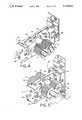
- FIG. 1is a perspective view of a preferred form of food roller dispenser in accordance with the present invention
- FIG. 2is a perspective view of the food roller dispenser of FIG. 1, but on a reduced scale, and showing partial removal of the roller assembly from its support bracket;
- FIG. 3is an enlarged fragmentary perspective view of the right end of the support bracket and roller assembly of FIG. 1;
- FIGS. 4 and 5are enlarged fragmentary perspective views of opposite ends of the food roller dispenser of FIG. 1, with portions of the roller assembly housings broken away to show the bearing supports at opposite ends of the rollers;
- FIGS. 6 and 7are enlarged fragmentary transverse sections through opposite ends of the food roller dispenser of FIG. 1, taken generally along the planes of the lines 6--6 and 7--7 thereof;
- FIG. 8is an enlarged schematic perspective view of the roller bearings and pillow block orientation at the left of the food roller dispenser of FIG. 1;
- FIG. 9is an enlarged schematic perspective view showing the manner in which the roller teeth mesh together to grip and squeeze out the contents of a flexible food container captured therebetween.
- roller assembly 2includes a pair of rollers 6 and 8 which may be counter rotated by operation of a hand crank 10 attached to one of the roller shafts as described hereafter.
- both rollers 6, 8are made of a single piece of relatively hard, nonporous plastic material such as acetal nylon which can easily be cleaned and is sanitarily acceptable for use in the food industry.
- both rollers 6, 8are generally circular in cross section and have a plurality of external, longitudinally extending teeth 12 around their outer peripheries which are pressed into meshing engagement with each other as described hereafter.
- the teeth 12are generally V-shaped and are configured to mate with each other as they come together in the area generally indicated by numeral 20.
- a flexible pouch-like food container 22 inserted between the rollers 6, 8is positively and mechanically gripped by the teeth 12, whereby the container will be driven between the rollers as the rollers are counter-rotated to force the removal of the contents from the flexible container.
- the roller assembly 2is designed for easy removal from the support bracket 4 to facilitate cleaning as is frequently necessary with food handling equipment.
- the support bracket 4is desirably provided with a pair of vertically spaced apart, horizontally extending channels 26, 28 which slidingly receive flanges 27, 29 respectively protruding above and below a beam-like support member 38 of the roller assembly 2, thus enabling the roller assembly to be easily removed from the support bracket 4.
- the roller assembly 2includes a pair of hollow box-like beams 30, 32 extending forwardly outwardly from opposite ends of the support member 38.
- Beams 30, 32are open at their outer ends and include longitudinal slots 34, 36 along one or both sides to permit reduced diameter portions 39 of the rollers 6, 8 adjacent opposite ends of the toothed roller portions 40 to be slid along the slots 34, 36 for locating roller bearing portions 42 within the beams.
- Each beam 30, 32is also adapted to snugly and slidably receive a pair of bearing blocks 44, 45 for supporting the roller bearing portions 42.
- the bearing blocks 44, 45are shown in FIGS. 6 and 7 as being made of plastic.
- a first bearing block 44is inserted into each beam 30, 32 through the open outer ends thereof followed by insertion of the roller bearing portions 42 of both rollers 6, 8. Then another bearing block 45 is inserted so that both roller bearing portions 42 are supported on opposite ends by the bearing blocks 44, 45. Accordingly, when the outer bearing block 45 is forced toward the inner bearing block 44, the toothed roller portions 40 of the rollers 6, 8 will be forced into meshing engagement with each other. The extent of such meshing engagement can be controlled as by providing thumbscrews 46 in cover plates 47 which are used to close off the open outer ends of the beams 30, 32 during use of the dispenser.
- the cover plates 47may be removably attached to the outer ends of beams 30, 32 using suitable fasteners such as bolts having easily removable acorn nuts 49 or the like on the outer ends thereof.
- the thumbscrews 46are threadedly received in openings in the end walls of the cover plates 47. When tightened, the thumbscrews 46 press against bearing plates 48 inserted within the respective beams outwardly of the outer bearing blocks 45 to exert an axial inward force against such outer bearing blocks (see FIGS. 6 and 7).
- a locknut 50 on each thumbscrew 46when tightened, holds the thumbscrews 46 and thus the bearing blocks 44, 45 in their desired position exerting an appropriate amount of force on the roller bearing surfaces 42 to squeeze the toothed roller portions 40 together.
- the roller bearing surfaces 42may vary, they should have a sufficient outer diameter and length to provide adequate support for the rollers 6, 8 to resist bending. Likewise, the reduced diameter portions 39 between the roller bearing surfaces 42 and the toothed roller portions 40 should be relatively shallow in depth and just wide enough to accommodate the thickness of the wall of the slots 34, 36 received therein so as not to adversely affect the rigidity of the rollers.
- the toothed portions 40 of the rollers 6, 8may have a maximum outer diameter of approximately 1.375 inch
- the reduced diameter portions 39may have an outer diameter of approximately 0.624 inch and a width of approximately 0.125 inch.
- the roller bearing surfaces 42may have an outer diameter of approximately 1.0 inch and an axial length of approximately 1.125 inch.
- the number and size of the roller teeth 12may vary within certain limits. However, in a preferred embodiment wherein the toothed roller portions 40 have a maximum outer diameter of approximately 1.375 inches as aforesaid, approximately seventy-two teeth 12 are desirably provided around the outer periphery of the rollers at 5° increments, each approximately 0.030 inch deep and having an included angle of between approximately 40° and 80°.
- roller teeth 12overlap a depth of approximately 0.025 inch where they come into full mating relationship.
- the amount of overlap between the teeth 12may be varied to accommodate different types and thicknesses of food containers by adjusting the spacing between the bearing blocks 44, 45.
- a stepped shoulder 51(FIGS. 6 and 7) is desirably provided at opposite ends of the toothed roller portions 40 having a width of approximately 0.125 inch and an outer diameter of approximately one inch, which subtantially corresponds to the outer diameter of the roller bearing portions 42.
- each roller 6, 8is a reduced diameter shaft extension 52, 54 which extends outwardly beyond the associated beam 32 to provide for attachment of a driving gear 56 and hand crank 10 to one of the rollers 8 and a driven gear 58 to the other roller 6.
- the gears 56, 58, as well as the hand crank 10may be suitably attached to the roller shaft extension 52, 54 as by means of set screws (not shown), and are in meshing engagement with each other, whereby rotation of the driving gear 56 and associated roller 8 in one direction will cause counter rotation of the driven gear 58 and associated roller 6.
- roller assembly 2To disassemble the entire roller assembly 2 for cleaning is a simple matter, it only being necessary to remove the fasteners 49, etc. that secure the cover plates 47 to the outer ends of the beams 30, 32. Once these plates 47 are removed, the bearing plates 48, bearing blocks 44, 45 and roller bearing portions 42 are easily slid out from within the respective beams 30, 32. After disassembly and cleaning, the roller assembly 2 is reassembled in reverse order to disassembly.
- the food roller dispenser 1 of the present inventionwill effectively dispense food from flexible pouch-like food containers 22.
- a top portion 68 of the container 22is inserted between the toothed roller portions 40 from below and the hand crank 10 is turned counterclockwise as viewed in FIG. 1 to cause the toothed roller portions 40 to engage the top of the container.
- the bottom portion 70 of the container 22is opened so that the contents 72 may be descharged as the container is advanced upwardly between the roller teeth 12 where they come together.
- roller teeth 12Cooperation of the roller teeth 12 as well as the driving engagement between the roller gears 56, 58 cause the container 22 to be advanced and squeezed between the roller teeth during rotation of the handle 10 in the required direction so that the contents of the flexible food container is discharged through a discharge opening 74 in the bottom of the container.
- the food roller dispenser 1 of the present inventionis easily disassembled for ease of cleaning and the rollers 6, 8 are made of a relatively hard, non-porous material suitable for use in the food industry and intermesh to prevent slippage of even the most slippery of flexible food containers, thereby making the dispenser a very desirable "squeeze all" dispenser.
Landscapes
- Engineering & Computer Science (AREA)
- Mechanical Engineering (AREA)
- Tubes (AREA)
Abstract
Description
This invention relates generally, as indicated, to a food roller dispenser for dispensing food from flexible food pouches and similar type containers.
Many food products such as toppings and other ingredients used in preparing foods commercially are prepackaged in flexible containers or pouches to reduce packaging costs as well as shipment and storage costs and for ease of handling and use of the food products. These flexible containers or pouches are usually designed so that one corner or end of the containers can be cut off and the contents squeezed out. Normally the flexible containers are hand squeezed, making it virtually impossible to remove the entire contents, resulting in some waste of the food product.
Squeeze roller dispensers of various types have been utilized in the past. One type of dispenser that has been used effectively for dispensing putty-like material from a flexible bag-like container is disclosed in U.S. Pat. No. 4,627,551, which is assigned to the same assignee as the present application. An objection to using this type of dispenser for dispensing food products is that the rollers are provided with rubber-like covers which are not acceptable for use in the food industry for sanitation reasons. Some materials that are suitable for use in industries in which sanitation is not a major concern may be sanitarily unsuitable for use in the food industry.
If the rollers are made of harder, less porous materials which are sanitarily acceptable in the food industry, a problem is then encountered with being able to effectively grip and drive the flexible food containers between the rollers without slippage. In the past, squeeze rollers have been provided with knurled surfaces for increased friction. However, it has been found that if this type of roller is used to dispense food from flexible containers, slippage results. Additionally, knurled surfaces are much harder to keep clean.
With the foregoing in mind, it is a principal object of this invention to provide a food roller dispenser for effectively removing substantially the entire contents of flexible food containers.
Another object is to provide such a food dispenser utilizing rollers made of a relatively hard, non-porous material that is sanitarily acceptable for use in the food industry.
Still another object is to provide such a food dispenser utilizing rollers of the type described that positively grip and drive a flexible food container therebetween without slippage to effect squeezing of the food product from the food container.
Still another object is to provide such a food roller dispenser which may be easily disassembled and cleaned with the frequency required in the food industry.
These and other objects of the present invention may be achieved by providing a food roller dispenser with a pair of elongated rollers having a plurality of circumferentially spaced teeth around the outer periphery of the rollers which mesh together during rotation of the rollers to grip and drive flexible food containers upwardly between the rollers to thereby remove substantially all of the food product from the food containers passing therebetween. The rollers are desirably made of a relatively hard, non-porous one piece plastic material which is substantially solid throughout. Adjacent opposite ends of the roller teeth are roller bearing portions which are supported by bearing blocks that may be moved relative to each other to control the amount of overlap between the roller teeth. To reduce roller deflection, the outer diameter of the rollers between the ends of the roller bearing portions is relatively large. Also, both the roller bearing portions and bearing blocks in which the roller bearing portions are supported are desirably of substantial length.
To the accomplishment of the foregoing and related ends, the invention, then, comprises the features hereinafter fully described and particularly pointed out in the claims, the following description and the annexed drawings setting forth in detail a certain illustrative embodiment of the invention, this being indicative, however, of but one of the various ways in which the principles of the invention may be employed.
In the annexed drawings:
FIG. 1 is a perspective view of a preferred form of food roller dispenser in accordance with the present invention;
FIG. 2 is a perspective view of the food roller dispenser of FIG. 1, but on a reduced scale, and showing partial removal of the roller assembly from its support bracket;
FIG. 3 is an enlarged fragmentary perspective view of the right end of the support bracket and roller assembly of FIG. 1;
FIGS. 4 and 5 are enlarged fragmentary perspective views of opposite ends of the food roller dispenser of FIG. 1, with portions of the roller assembly housings broken away to show the bearing supports at opposite ends of the rollers;
FIGS. 6 and 7 are enlarged fragmentary transverse sections through opposite ends of the food roller dispenser of FIG. 1, taken generally along the planes of thelines 6--6 and 7--7 thereof;
FIG. 8 is an enlarged schematic perspective view of the roller bearings and pillow block orientation at the left of the food roller dispenser of FIG. 1; and
FIG. 9 is an enlarged schematic perspective view showing the manner in which the roller teeth mesh together to grip and squeeze out the contents of a flexible food container captured therebetween.
Referring now in detail to the drawings, and initially to FIG. 1, there is shown a preferred form of food roller dispenser 1 in accordance with this invention including aroller assembly 2 supported by a support bracket 4.Roller assembly 2 includes a pair ofrollers hand crank 10 attached to one of the roller shafts as described hereafter. Preferably, bothrollers
Referring further to FIG. 1 and also FIGS. 4, 5 and 9, it will be seen that bothrollers teeth 12 around their outer peripheries which are pressed into meshing engagement with each other as described hereafter. As best seen in FIG. 9, theteeth 12 are generally V-shaped and are configured to mate with each other as they come together in the area generally indicated bynumeral 20. In this area, a flexible pouch-like food container 22 inserted between therollers teeth 12, whereby the container will be driven between the rollers as the rollers are counter-rotated to force the removal of the contents from the flexible container.
With reference to FIGS. 2 and 3, it will be appreciated that theroller assembly 2 is designed for easy removal from the support bracket 4 to facilitate cleaning as is frequently necessary with food handling equipment. To that end, the support bracket 4 is desirably provided with a pair of vertically spaced apart, horizontally extendingchannels flanges like support member 38 of theroller assembly 2, thus enabling the roller assembly to be easily removed from the support bracket 4.
Once removed, theroller assembly 2 is easily disassembled so that its parts may be properly cleaned and sanitized. As can be seen in FIGS. 1 and 4-7, theroller assembly 2 includes a pair of hollow box-like beams support member 38.Beams longitudinal slots diameter portions 39 of therollers toothed roller portions 40 to be slid along theslots portions 42 within the beams. Eachbeam bearing blocks portions 42. Thebearing blocks
During assembly, a first bearingblock 44 is inserted into eachbeam portions 42 of bothrollers bearing block 45 is inserted so that both roller bearingportions 42 are supported on opposite ends by thebearing blocks outer bearing block 45 is forced toward the inner bearingblock 44, thetoothed roller portions 40 of therollers thumbscrews 46 incover plates 47 which are used to close off the open outer ends of thebeams
Thecover plates 47 may be removably attached to the outer ends ofbeams removable acorn nuts 49 or the like on the outer ends thereof. Thethumbscrews 46 are threadedly received in openings in the end walls of thecover plates 47. When tightened, thethumbscrews 46 press againstbearing plates 48 inserted within the respective beams outwardly of theouter bearing blocks 45 to exert an axial inward force against such outer bearing blocks (see FIGS. 6 and 7). Alocknut 50 on eachthumbscrew 46, when tightened, holds thethumbscrews 46 and thus thebearing blocks surfaces 42 to squeeze thetoothed roller portions 40 together.
Although the dimensions of the roller bearingsurfaces 42 may vary, they should have a sufficient outer diameter and length to provide adequate support for therollers diameter portions 39 between the roller bearingsurfaces 42 and thetoothed roller portions 40 should be relatively shallow in depth and just wide enough to accommodate the thickness of the wall of theslots toothed portions 40 of therollers diameter portions 39 may have an outer diameter of approximately 0.624 inch and a width of approximately 0.125 inch. Also, the roller bearingsurfaces 42 may have an outer diameter of approximately 1.0 inch and an axial length of approximately 1.125 inch.
Likewise, the number and size of theroller teeth 12 may vary within certain limits. However, in a preferred embodiment wherein thetoothed roller portions 40 have a maximum outer diameter of approximately 1.375 inches as aforesaid, approximately seventy-twoteeth 12 are desirably provided around the outer periphery of the rollers at 5° increments, each approximately 0.030 inch deep and having an included angle of between approximately 40° and 80°.
With the roller dimensions as given, it is desirable to have theroller teeth 12 overlap a depth of approximately 0.025 inch where they come into full mating relationship. However, it will be appreciated that the amount of overlap between theteeth 12 may be varied to accommodate different types and thicknesses of food containers by adjusting the spacing between thebearing blocks
To reduce friction between the inside walls of thebeams rollers toothed roller portions 40 having a width of approximately 0.125 inch and an outer diameter of approximately one inch, which subtantially corresponds to the outer diameter of theroller bearing portions 42.
At one end of eachroller diameter shaft extension beam 32 to provide for attachment of adriving gear 56 and hand crank 10 to one of therollers 8 and a drivengear 58 to theother roller 6. Thegears roller shaft extension driving gear 56 and associatedroller 8 in one direction will cause counter rotation of the drivengear 58 and associatedroller 6.
To disassemble theentire roller assembly 2 for cleaning is a simple matter, it only being necessary to remove thefasteners 49, etc. that secure thecover plates 47 to the outer ends of thebeams plates 47 are removed, the bearingplates 48, bearing blocks 44, 45 androller bearing portions 42 are easily slid out from within therespective beams roller assembly 2 is reassembled in reverse order to disassembly.
From the foregoing, it will be apparent that the food roller dispenser 1 of the present invention will effectively dispense food from flexible pouch-like food containers 22. In use, atop portion 68 of thecontainer 22 is inserted between thetoothed roller portions 40 from below and the hand crank 10 is turned counterclockwise as viewed in FIG. 1 to cause thetoothed roller portions 40 to engage the top of the container. Next thebottom portion 70 of thecontainer 22 is opened so that thecontents 72 may be descharged as the container is advanced upwardly between theroller teeth 12 where they come together. Cooperation of theroller teeth 12 as well as the driving engagement between the roller gears 56, 58 cause thecontainer 22 to be advanced and squeezed between the roller teeth during rotation of thehandle 10 in the required direction so that the contents of the flexible food container is discharged through adischarge opening 74 in the bottom of the container.
Also from the foregoing it will be appreciated that the food roller dispenser 1 of the present invention is easily disassembled for ease of cleaning and therollers
Although the invention had been shown and described with respect to a certain preferred embodiment, it is obvious that equivalent alterations and modifications will occur to others skilled in the art upon the reading and understanding of the specification. The present invention includes all such equivalent alterations and modifications and is limited only by the scope of the claims.
Claims (12)
1. A food roller dispenser for dispensing the contents of a flexible pouch-like container comprising a roller assembly including a pair of roller means having container engaging roller portions which drivingly grip said flexible pouch-like container to squeeze the contents from said container during counter-rotation of said roller means, support means for said roller means having a pair of hollow beams extending outwardly from one side of said support means in spaced apart relation, said beams having open outer ends for sliding receipt of a pair of spaced apart bearing blocks in each of said beams which support roller bearing portions on said roller means adjacent opposite ends of said roller means, and removable cover plate means for closing off said open outer ends of said beams, said cover plate means being removable to permit insertion and removal of said bearing blocks and said roller bearing portions from said beams for ease of cleaning, one of said bearing blocks of each pair being rigidly supported adjacent an inner end of said beams, and means for moving the other of said bearing blocks of each pair toward said one bearing block for exerting an axial force against said roller bearing portions positioned between said bearing blocks to vary the gripping force of said roller portions against said container passing therebetween, each of said roller means including said roller portions and said roller bearing portions being made of a single piece of a relatively hard, non-porous plastic material, each of said roller means including integral reduced diameter portions between said roller portions and said roller bearing portions which are slidably received in slots in the sides of said beams for locating said roller bearing portions within said beams.
2. The food roller dispenser of claim 1 wherein said reduced diameter portions of said roller means have an axial length just long enough to be slidably received in said slots.
3. The food roller dispenser of claim 2 wherein said roller bearing portions have an axial length substantially greater than the axial length of said reduced diameter portions.
4. The food roller dispenser of claim 3 wherein said roller bearing portions have an outer diameter substantially greater than the outer diameter of said reduced diameter portions and less than the outer diameter of said roller portions.
5. The food roller dispenser of claim 4 wherein said roller means have integral stepped shoulders at opposite ends of said roller portions, said stepped shoulders having an outer diameter substantially corresponding to the outer diameter of said roller bearing portions and having an axial length substantially corresponding to the axial length of said reduced diameter portions.
6. The food roller dispenser of claim 2 wherein each of said roller means have smaller diameter integral shaft extensions which extend through additional slots in said beams, and gears on said shaft extensions in mating engagement with each other, whereby rotation of one of said roller means causes counter-rotation of the other of said roller means.
7. The food roller dispenser of claim 2 wherein said roller portions have cooperating teeth which overlap each other during counter-rotation of said roller means to drivingly grip said flexible container between said roller portions and squeeze the contents from said container during movement of said container between said roller portions, said teeth being generally V-shape, and at approximately 5° increments around the periphery of said roller portions.
8. The food roller dispenser of claim 7 wherein said teeth overlap a depth of approximately 0.025 inch where said teeth come into full mating relationship.
9. The food roller dispenser of claim 6 wherein one of said shaft extensions extends outwardly beyond one of said gears for mounting of a handcrank on said one shaft extension for turning of said one shaft extension.
10. The food roller dispenser of claim 2 further comprising a support bracket for said roller assembly, said support bracket having a pair of vertically spaced apart, horizontally-extending channels for sliding receipt of flanges on said roller assembly for ease of removal and assembly of said roller assembly onto said support bracket.
11. A food roller dispenser for dispensing the contents of a flexible pouch-like container comprising a roller assembly including a pair of roller means having container engaging roller portions which drivingly grip said flexible pouch-like container to squeeze the contents from said container during counter-rotation of said roller means, support means for said roller means having a pair of hollow beams extending outwardly from one side of said support means in spaced apart relation, said beams having open outer ends for sliding receipt of a pair of spaced apart bearing blocks in each of said beams which support roller bearing portions on said roller means adjacent opposite ends of said roller means, and removable cover plate means for closing off said open outer ends of said beams, said cover plate means being removable to permit insertion and removal of said bearing blocks and said roller bearing portions from said beams for ease of cleaning, one of said bearing blocks of each pair being rigidly supported adjacent an inner end of said beams, and means for moving the other of said bearing blocks of each pair toward said one bearing block for exerting an axial force against said roller bearing portions positioned between said bearing blocks to vary the gripping force of said roller portions against said container passing therebetween, said bearing blocks being made of plastic, and said means for moving said other bearing block of each pair toward said one bearing block comprising bearing plates slidably received in said beams, said bearing plates being disposed axially outwardly of said other bearing blocks, and rotatable thumbscrew means extending through said cover means into engagement with said bearing plates for exerting an axial force against said bearing plates thus urging said other bearing blocks towards said one bearing blocks.
12. A food roller dispenser for dispensing the contents of a flexible pouch-like container comprising a roller assembly including a pair of roller means having container engaging roller portions which drivingly grip said flexible pouch-like container to squeeze the contents from said container during counter-rotation of said roller means, support means for said roller means having a pair of hollow beams extending outwardly from one side of said support means in spaced apart relation, said beams having open outer ends for sliding receipt of a pair of spaced apart bearing blocks in each of said beams which support roller bearing portions on said roller means adjacent opposite ends of said roller means, and removable cover plate means for closing off said open outer ends of said beams, said cover plate means being removable to permit insertion and removal of said bearing blocks and said roller bearing portions from said beams for ease of cleaning, one of said bearing blocks of each pair being rigidly supported adjacent an inner end of said beams, and means for moving the other of said bearing blocks of each pair toward said one bearing block for exerting an axial force against said roller bearing portions positioned between said bearing blocks to vary the gripping force of said roller portions against said container passing therebetween, each of said roller means including said roller portions and said roller bearing portions being made of a single piece of a relatively hard, non-porous plastic material.
Priority Applications (1)
| Application Number | Priority Date | Filing Date | Title |
|---|---|---|---|
| US07/622,510US5118011A (en) | 1990-12-05 | 1990-12-05 | Food roller dispenser |
Applications Claiming Priority (1)
| Application Number | Priority Date | Filing Date | Title |
|---|---|---|---|
| US07/622,510US5118011A (en) | 1990-12-05 | 1990-12-05 | Food roller dispenser |
Publications (1)
| Publication Number | Publication Date |
|---|---|
| US5118011Atrue US5118011A (en) | 1992-06-02 |
Family
ID=24494439
Family Applications (1)
| Application Number | Title | Priority Date | Filing Date |
|---|---|---|---|
| US07/622,510Expired - Fee RelatedUS5118011A (en) | 1990-12-05 | 1990-12-05 | Food roller dispenser |
Country Status (1)
| Country | Link |
|---|---|
| US (1) | US5118011A (en) |
Cited By (26)
| Publication number | Priority date | Publication date | Assignee | Title |
|---|---|---|---|---|
| US5178302A (en)* | 1992-01-02 | 1993-01-12 | Cheng Kweng Ming | Tooth paste squeezing device with a spring biased roller assembly |
| US5490613A (en)* | 1994-07-07 | 1996-02-13 | The Clorox Company | Viscous fluid dispenser |
| US5578001A (en)* | 1994-09-13 | 1996-11-26 | Shah; Pranav N. | Infusion apparatus for IV bags |
| US5657903A (en)* | 1996-04-17 | 1997-08-19 | Roberts; Jodie Schmidt | Device for emptying contents from a flexible container |
| US5765723A (en)* | 1996-08-05 | 1998-06-16 | A. R. Arena Products, Inc. | Bag evacuator |
| DE29810207U1 (en) | 1998-06-08 | 1998-09-17 | Klotzsche, Karl, 31008 Elze | Tube press |
| WO2000032488A1 (en)* | 1998-12-02 | 2000-06-08 | Arturo Campos Marques | Squeezer for dental paste |
| US6074366A (en)* | 1998-01-16 | 2000-06-13 | Tandem Medical Inc. | Medication delivery apparatus |
| US6089401A (en)* | 1996-01-23 | 2000-07-18 | Sca Hygiene Paper Ab | Braking arrangement for dispensers of continuous material |
| US20030139274A1 (en)* | 2002-01-24 | 2003-07-24 | Bobst S.A. | Device for rotary converting a web or sheet matter |
| US6726655B1 (en) | 1999-11-05 | 2004-04-27 | Tandem Medical | Medication delivery system |
| US20050167444A1 (en)* | 2004-01-07 | 2005-08-04 | Sanfilippo James J. | Roller assembly for flexible bags |
| US6966457B1 (en)* | 2004-01-08 | 2005-11-22 | Eric Torbet | Spring-loaded tube squeezing device |
| US20070068969A1 (en)* | 2005-09-23 | 2007-03-29 | Orzech Thomas S | Food dispenser with pump for dispensing from a plurality of sources |
| US20070068966A1 (en)* | 2005-09-23 | 2007-03-29 | Orzech Thomas S | Food dispenser with pump for easy loading of containers therein |
| US7309055B1 (en)* | 2004-09-07 | 2007-12-18 | Spiegel Aldona J | Apparatus for flushing fluids from a tube |
| US20090102418A1 (en)* | 2007-10-17 | 2009-04-23 | Benny Gaber | Manual dynamo charger for recharging portable electronic devices |
| US20090302054A1 (en)* | 2008-06-04 | 2009-12-10 | Julio Cragnolini | Tube squeezing device |
| US20100127112A1 (en)* | 2008-11-21 | 2010-05-27 | Ideepak Holding B.V. | Apparatus And Method For Dispensing A Deformable Web |
| US20100258579A1 (en)* | 2009-04-14 | 2010-10-14 | Sca Tissue North America Llc | Continuous feed material dispenser with adjustable brake |
| WO2011080402A1 (en)* | 2010-01-04 | 2011-07-07 | Oy Fluid-Bag Ab | Emptying arrangement and method for emptying a flexible container |
| FR2990424A1 (en)* | 2012-05-10 | 2013-11-15 | Applic Tech Ind De Mecanique Atim Innovation | Device for drying bag filled with e.g. cosmetic product, fixed in container, has electric actuation element mounted on frame support so as to control rotational movements of frame in vertical plane and translation of rollers |
| WO2017022867A1 (en)* | 2015-07-31 | 2017-02-09 | 정태봉 | Tube squeezer |
| CN107472724A (en)* | 2017-08-03 | 2017-12-15 | 上海鸿研物流技术有限公司 | Fluid discharge system and its crowded thruster |
| WO2019024769A1 (en)* | 2017-08-03 | 2019-02-07 | 上海鸿研物流技术有限公司 | Fluid discharge system and its squeezer |
| US11608214B2 (en)* | 2018-10-08 | 2023-03-21 | The Cube Club Platform Gmbh | Device for squeezing out tubes |
Citations (8)
| Publication number | Priority date | Publication date | Assignee | Title |
|---|---|---|---|---|
| US1783101A (en)* | 1929-06-19 | 1930-11-25 | Atlantic Service Company Inc | Toilet-paste-tube compressor |
| US2037138A (en)* | 1935-09-25 | 1936-04-14 | Fred R Mcconnon | Apparatus for collapsing flexible containers |
| US2567767A (en)* | 1947-12-19 | 1951-09-11 | Leo C Sheppler | Dispenser for collapsible tubes |
| US2734662A (en)* | 1956-02-14 | shippen | ||
| US4213542A (en)* | 1979-03-07 | 1980-07-22 | Wilson Bobby R | Tooth paste dispenser |
| US4287921A (en)* | 1979-06-05 | 1981-09-08 | Sanford Robert B | Canister set |
| US4354623A (en)* | 1980-07-07 | 1982-10-19 | Gill John B | Heavy duty tube wringing device |
| US4627551A (en)* | 1984-03-05 | 1986-12-09 | Oatey Co. | Dispenser system and method for dispensing putty-like material |
- 1990
- 1990-12-05USUS07/622,510patent/US5118011A/ennot_activeExpired - Fee Related
Patent Citations (8)
| Publication number | Priority date | Publication date | Assignee | Title |
|---|---|---|---|---|
| US2734662A (en)* | 1956-02-14 | shippen | ||
| US1783101A (en)* | 1929-06-19 | 1930-11-25 | Atlantic Service Company Inc | Toilet-paste-tube compressor |
| US2037138A (en)* | 1935-09-25 | 1936-04-14 | Fred R Mcconnon | Apparatus for collapsing flexible containers |
| US2567767A (en)* | 1947-12-19 | 1951-09-11 | Leo C Sheppler | Dispenser for collapsible tubes |
| US4213542A (en)* | 1979-03-07 | 1980-07-22 | Wilson Bobby R | Tooth paste dispenser |
| US4287921A (en)* | 1979-06-05 | 1981-09-08 | Sanford Robert B | Canister set |
| US4354623A (en)* | 1980-07-07 | 1982-10-19 | Gill John B | Heavy duty tube wringing device |
| US4627551A (en)* | 1984-03-05 | 1986-12-09 | Oatey Co. | Dispenser system and method for dispensing putty-like material |
Cited By (40)
| Publication number | Priority date | Publication date | Assignee | Title |
|---|---|---|---|---|
| US5178302A (en)* | 1992-01-02 | 1993-01-12 | Cheng Kweng Ming | Tooth paste squeezing device with a spring biased roller assembly |
| US5490613A (en)* | 1994-07-07 | 1996-02-13 | The Clorox Company | Viscous fluid dispenser |
| US5578001A (en)* | 1994-09-13 | 1996-11-26 | Shah; Pranav N. | Infusion apparatus for IV bags |
| US6089401A (en)* | 1996-01-23 | 2000-07-18 | Sca Hygiene Paper Ab | Braking arrangement for dispensers of continuous material |
| US5657903A (en)* | 1996-04-17 | 1997-08-19 | Roberts; Jodie Schmidt | Device for emptying contents from a flexible container |
| US5765723A (en)* | 1996-08-05 | 1998-06-16 | A. R. Arena Products, Inc. | Bag evacuator |
| US6146360A (en)* | 1998-01-16 | 2000-11-14 | Tandem Medical, Inc. | Medication delivery apparatus |
| US6416496B1 (en) | 1998-01-16 | 2002-07-09 | Tandem Medical, Inc. | Medication delivery apparatus |
| US6074366A (en)* | 1998-01-16 | 2000-06-13 | Tandem Medical Inc. | Medication delivery apparatus |
| DE29810207U1 (en) | 1998-06-08 | 1998-09-17 | Klotzsche, Karl, 31008 Elze | Tube press |
| WO2000032488A1 (en)* | 1998-12-02 | 2000-06-08 | Arturo Campos Marques | Squeezer for dental paste |
| US6726655B1 (en) | 1999-11-05 | 2004-04-27 | Tandem Medical | Medication delivery system |
| US20030139274A1 (en)* | 2002-01-24 | 2003-07-24 | Bobst S.A. | Device for rotary converting a web or sheet matter |
| US7060016B2 (en)* | 2002-01-24 | 2006-06-13 | Bobst S.A. | Device for rotary converting a web or sheet matter |
| US20050167444A1 (en)* | 2004-01-07 | 2005-08-04 | Sanfilippo James J. | Roller assembly for flexible bags |
| US6966457B1 (en)* | 2004-01-08 | 2005-11-22 | Eric Torbet | Spring-loaded tube squeezing device |
| US7309055B1 (en)* | 2004-09-07 | 2007-12-18 | Spiegel Aldona J | Apparatus for flushing fluids from a tube |
| US20070068969A1 (en)* | 2005-09-23 | 2007-03-29 | Orzech Thomas S | Food dispenser with pump for dispensing from a plurality of sources |
| US20070068966A1 (en)* | 2005-09-23 | 2007-03-29 | Orzech Thomas S | Food dispenser with pump for easy loading of containers therein |
| US20100258590A1 (en)* | 2005-09-23 | 2010-10-14 | Nestec S.A. | Food dispenser with pump for easy loading of containers therein |
| US7651010B2 (en) | 2005-09-23 | 2010-01-26 | Nestec S.A. | Food dispenser with pump for dispensing from a plurality of sources |
| US20090102418A1 (en)* | 2007-10-17 | 2009-04-23 | Benny Gaber | Manual dynamo charger for recharging portable electronic devices |
| US20090302054A1 (en)* | 2008-06-04 | 2009-12-10 | Julio Cragnolini | Tube squeezing device |
| US20100127112A1 (en)* | 2008-11-21 | 2010-05-27 | Ideepak Holding B.V. | Apparatus And Method For Dispensing A Deformable Web |
| US20100258579A1 (en)* | 2009-04-14 | 2010-10-14 | Sca Tissue North America Llc | Continuous feed material dispenser with adjustable brake |
| US8256700B2 (en) | 2009-04-14 | 2012-09-04 | Sca Tissue North America Llc | Continuous feed material dispenser with adjustable brake |
| US8616486B2 (en) | 2009-04-14 | 2013-12-31 | Sca Tissue North America Llc | Continuous feed material dispenser with adjustable brake |
| US9499369B2 (en) | 2009-04-14 | 2016-11-22 | Sca Tissue North America Llc | Continuous feed material dispenser with adjustable brake |
| WO2011080402A1 (en)* | 2010-01-04 | 2011-07-07 | Oy Fluid-Bag Ab | Emptying arrangement and method for emptying a flexible container |
| FR2990424A1 (en)* | 2012-05-10 | 2013-11-15 | Applic Tech Ind De Mecanique Atim Innovation | Device for drying bag filled with e.g. cosmetic product, fixed in container, has electric actuation element mounted on frame support so as to control rotational movements of frame in vertical plane and translation of rollers |
| JP2017533147A (en)* | 2015-07-31 | 2017-11-09 | テボン ジュン | Tube press |
| WO2017022867A1 (en)* | 2015-07-31 | 2017-02-09 | 정태봉 | Tube squeezer |
| CN107472724A (en)* | 2017-08-03 | 2017-12-15 | 上海鸿研物流技术有限公司 | Fluid discharge system and its crowded thruster |
| WO2019024769A1 (en)* | 2017-08-03 | 2019-02-07 | 上海鸿研物流技术有限公司 | Fluid discharge system and its squeezer |
| WO2019024770A1 (en)* | 2017-08-03 | 2019-02-07 | 上海鸿研物流技术有限公司 | Fluid drainage system and squeezing and pushing apparatus thereof |
| AU2018310374B2 (en)* | 2017-08-03 | 2021-11-11 | Shanghai Hongyan Returnable Transit Packagings Co., Ltd. | Fluid discharge system and the squeezer thereof |
| US11235922B2 (en) | 2017-08-03 | 2022-02-01 | Shanghai Hongyan Returnable Transit Packagings Co., Ltd. | Fluid discharge system and squeezer thereof |
| AU2018310374C1 (en)* | 2017-08-03 | 2022-03-03 | Shanghai Hongyan Returnable Transit Packagings Co., Ltd. | Fluid discharge system and the squeezer thereof |
| US11305933B2 (en) | 2017-08-03 | 2022-04-19 | Shanghai Hongyan Returnable Transit Packagings Co., Ltd. | Fluid discharge system and squeezer thereof |
| US11608214B2 (en)* | 2018-10-08 | 2023-03-21 | The Cube Club Platform Gmbh | Device for squeezing out tubes |
Similar Documents
| Publication | Publication Date | Title |
|---|---|---|
| US5118011A (en) | Food roller dispenser | |
| EP2695548B1 (en) | Dispensing device for metering flowable media | |
| EP1913817B1 (en) | Device to allow for cleaning access in semi-solid food product metering machines | |
| US7540235B2 (en) | Device for pressing empty containers together and method therefor | |
| EP0509230B2 (en) | Feed mechanism for a cutting machine for cutting edible products | |
| US20070295583A1 (en) | Sanitary conveyor center drive assembly | |
| US3277846A (en) | Machine for making multiple laminated food loaf | |
| US4421252A (en) | Toothpaste dispensing device | |
| CH632202A5 (en) | METHOD AND DEVICE FOR CARTONING FILLED BAG-LIKE CONTAINERS. | |
| US5186098A (en) | Apparatus for buttering and applying cheese topping to bread | |
| US5862743A (en) | Apportioning device for dough | |
| EP1736055A2 (en) | Apparatus for making dough pockets. | |
| DE2423885A1 (en) | DEVICE FOR STORING AND FEEDING SHEET-SHAPED MATERIAL SECTIONS, IN PARTICULAR OF STIFFPAPER PIECES, LABELS AND THE LIKE. TO MACHINERY FOR PACKING CIGARETTES IN PACKAGES WITH HINGED LIDS | |
| US12213487B2 (en) | Cookie molding machine | |
| EP1544138B1 (en) | Loss-in-weight feeder for powders and dry goods | |
| US4666069A (en) | Apparatus for dispensing particulate material | |
| DE2138253A1 (en) | Packaging device for continuously delivered articles, in particular cheese slices | |
| US4862796A (en) | Apparatus for crushing cans | |
| US4354623A (en) | Heavy duty tube wringing device | |
| GB2259043A (en) | Apparatus for shaping food products | |
| EP0375877A2 (en) | Separating apparatus | |
| EP4403033B1 (en) | Pastry forming machine and method of pastry forming | |
| DE236101C (en) | ||
| DE1753121C3 (en) | Machine for processing fish fillets | |
| GB2106774A (en) | Method of an apparatus for unwrapping foodstuffs |
Legal Events
| Date | Code | Title | Description |
|---|---|---|---|
| AS | Assignment | Owner name:OATEY CO., OHIO Free format text:ASSIGNMENT OF ASSIGNORS INTEREST.;ASSIGNOR:KOPP, RAUN A.;REEL/FRAME:005533/0498 Effective date:19901203 | |
| REMI | Maintenance fee reminder mailed | ||
| LAPS | Lapse for failure to pay maintenance fees | ||
| FP | Lapsed due to failure to pay maintenance fee | Effective date:19960605 | |
| AS | Assignment | Owner name:KEYBANK NATIONAL ASSOCIATION, AS AGENT, OHIO Free format text:SECURITY AGREEMENT;ASSIGNOR:OATEY CO.;REEL/FRAME:018972/0226 Effective date:20061214 | |
| AS | Assignment | Owner name:OATEY CO., OHIO Free format text:RELEASE BY SECURED PARTY;ASSIGNOR:KEYBANK NATIONAL ASSOCIATION, AS COLLATERAL AGENT;REEL/FRAME:032380/0793 Effective date:20140228 | |
| STCH | Information on status: patent discontinuation | Free format text:PATENT EXPIRED DUE TO NONPAYMENT OF MAINTENANCE FEES UNDER 37 CFR 1.362 |