US5117915A - Well casing flotation device and method - Google Patents
Well casing flotation device and methodDownload PDFInfo
- Publication number
- US5117915A US5117915AUS07/569,691US56969190AUS5117915AUS 5117915 AUS5117915 AUS 5117915AUS 56969190 AUS56969190 AUS 56969190AUS 5117915 AUS5117915 AUS 5117915A
- Authority
- US
- United States
- Prior art keywords
- fluid
- duct
- flotation
- location
- hole
- Prior art date
- Legal status (The legal status is an assumption and is not a legal conclusion. Google has not performed a legal analysis and makes no representation as to the accuracy of the status listed.)
- Expired - Lifetime
Links
- 238000005188flotationMethods0.000titleclaimsdescription122
- 238000000034methodMethods0.000titleclaimsdescription98
- 239000012530fluidSubstances0.000claimsabstractdescription220
- 230000008569processEffects0.000claimsdescription63
- 238000005553drillingMethods0.000claimsdescription61
- 239000004568cementSubstances0.000claimsdescription53
- 239000002002slurrySubstances0.000claimsdescription37
- 238000006073displacement reactionMethods0.000claimsdescription17
- 230000015572biosynthetic processEffects0.000claimsdescription9
- 230000008859changeEffects0.000claimsdescription5
- 239000000463materialSubstances0.000claimsdescription5
- 230000005484gravityEffects0.000claimsdescription4
- 239000007788liquidSubstances0.000claimsdescription4
- 238000005086pumpingMethods0.000claimsdescription4
- 238000007789sealingMethods0.000claimsdescription3
- 239000004215Carbon black (E152)Substances0.000claimsdescription2
- 230000007423decreaseEffects0.000claimsdescription2
- 229930195733hydrocarbonNatural products0.000claimsdescription2
- 150000002430hydrocarbonsChemical class0.000claimsdescription2
- 238000007654immersionMethods0.000claims1
- 230000008901benefitEffects0.000description11
- 238000007667floatingMethods0.000description9
- 238000009434installationMethods0.000description9
- 238000013022ventingMethods0.000description9
- 239000007787solidSubstances0.000description7
- 238000004519manufacturing processMethods0.000description6
- 238000013459approachMethods0.000description5
- 238000005452bendingMethods0.000description5
- 230000002706hydrostatic effectEffects0.000description5
- 238000010008shearingMethods0.000description5
- 238000012360testing methodMethods0.000description5
- 238000004891communicationMethods0.000description4
- 230000013011matingEffects0.000description4
- 238000010276constructionMethods0.000description3
- 238000009826distributionMethods0.000description3
- 230000000694effectsEffects0.000description3
- 230000001050lubricating effectEffects0.000description3
- 238000012986modificationMethods0.000description3
- 230000004048modificationEffects0.000description3
- 230000007935neutral effectEffects0.000description3
- 2299100010946061 aluminium alloyInorganic materials0.000description2
- IJGRMHOSHXDMSA-UHFFFAOYSA-NAtomic nitrogenChemical compoundN#NIJGRMHOSHXDMSA-UHFFFAOYSA-N0.000description2
- 239000007789gasSubstances0.000description2
- 238000005461lubricationMethods0.000description2
- 230000009467reductionEffects0.000description2
- 238000013519translationMethods0.000description2
- XLYOFNOQVPJJNP-UHFFFAOYSA-NwaterSubstancesOXLYOFNOQVPJJNP-UHFFFAOYSA-N0.000description2
- GICIECWTEWJCRE-UHFFFAOYSA-N3,4,4,7-tetramethyl-2,3-dihydro-1h-naphthaleneChemical compoundCC1=CC=C2C(C)(C)C(C)CCC2=C1GICIECWTEWJCRE-UHFFFAOYSA-N0.000description1
- 230000009471actionEffects0.000description1
- XAGFODPZIPBFFR-UHFFFAOYSA-NaluminiumChemical compound[Al]XAGFODPZIPBFFR-UHFFFAOYSA-N0.000description1
- 229910052782aluminiumInorganic materials0.000description1
- 230000002457bidirectional effectEffects0.000description1
- 230000005465channelingEffects0.000description1
- 238000004140cleaningMethods0.000description1
- 230000006835compressionEffects0.000description1
- 238000007906compressionMethods0.000description1
- 238000005520cutting processMethods0.000description1
- 238000013461designMethods0.000description1
- 238000005516engineering processMethods0.000description1
- 239000006260foamSubstances0.000description1
- 238000002347injectionMethods0.000description1
- 239000007924injectionSubstances0.000description1
- 238000003780insertionMethods0.000description1
- 230000037431insertionEffects0.000description1
- 239000003562lightweight materialSubstances0.000description1
- 239000000314lubricantSubstances0.000description1
- 238000012423maintenanceMethods0.000description1
- 238000013508migrationMethods0.000description1
- 230000005012migrationEffects0.000description1
- 239000000203mixtureSubstances0.000description1
- 210000002445nippleAnatomy0.000description1
- 229910052757nitrogenInorganic materials0.000description1
- 239000002245particleSubstances0.000description1
- 230000035699permeabilityEffects0.000description1
- 230000002265preventionEffects0.000description1
- 230000000717retained effectEffects0.000description1
- 238000007790scrapingMethods0.000description1
- 230000035939shockEffects0.000description1
- 239000011343solid materialSubstances0.000description1
- 230000003068static effectEffects0.000description1
- 238000003860storageMethods0.000description1
- 238000011144upstream manufacturingMethods0.000description1
Images


Classifications
- E—FIXED CONSTRUCTIONS
- E21—EARTH OR ROCK DRILLING; MINING
- E21B—EARTH OR ROCK DRILLING; OBTAINING OIL, GAS, WATER, SOLUBLE OR MELTABLE MATERIALS OR A SLURRY OF MINERALS FROM WELLS
- E21B43/00—Methods or apparatus for obtaining oil, gas, water, soluble or meltable materials or a slurry of minerals from wells
- E21B43/02—Subsoil filtering
- E21B43/10—Setting of casings, screens, liners or the like in wells
- E—FIXED CONSTRUCTIONS
- E21—EARTH OR ROCK DRILLING; MINING
- E21B—EARTH OR ROCK DRILLING; OBTAINING OIL, GAS, WATER, SOLUBLE OR MELTABLE MATERIALS OR A SLURRY OF MINERALS FROM WELLS
- E21B23/00—Apparatus for displacing, setting, locking, releasing or removing tools, packers or the like in boreholes or wells
- E21B23/08—Introducing or running tools by fluid pressure, e.g. through-the-flow-line tool systems
- E—FIXED CONSTRUCTIONS
- E21—EARTH OR ROCK DRILLING; MINING
- E21B—EARTH OR ROCK DRILLING; OBTAINING OIL, GAS, WATER, SOLUBLE OR MELTABLE MATERIALS OR A SLURRY OF MINERALS FROM WELLS
- E21B31/00—Fishing for or freeing objects in boreholes or wells
- E21B31/035—Fishing for or freeing objects in boreholes or wells controlling differential pipe sticking
- E—FIXED CONSTRUCTIONS
- E21—EARTH OR ROCK DRILLING; MINING
- E21B—EARTH OR ROCK DRILLING; OBTAINING OIL, GAS, WATER, SOLUBLE OR MELTABLE MATERIALS OR A SLURRY OF MINERALS FROM WELLS
- E21B33/00—Sealing or packing boreholes or wells
- E21B33/10—Sealing or packing boreholes or wells in the borehole
- E21B33/13—Methods or devices for cementing, for plugging holes, crevices or the like
- E21B33/14—Methods or devices for cementing, for plugging holes, crevices or the like for cementing casings into boreholes
- E21B33/16—Methods or devices for cementing, for plugging holes, crevices or the like for cementing casings into boreholes using plugs for isolating cement charge; Plugs therefor
- E—FIXED CONSTRUCTIONS
- E21—EARTH OR ROCK DRILLING; MINING
- E21B—EARTH OR ROCK DRILLING; OBTAINING OIL, GAS, WATER, SOLUBLE OR MELTABLE MATERIALS OR A SLURRY OF MINERALS FROM WELLS
- E21B7/00—Special methods or apparatus for drilling
- E21B7/04—Directional drilling
Definitions
- This inventionrelates to well drilling and well completion devices and processes. More specifically, the invention relates to an apparatus and method of setting liner or casing strings in an extended reach well, during oil, gas or other well completions.
- the liner or casing stringis set in a pre-drilled hole.
- the drill string and bit used to cut the holeis rotated, thereby reducing drag forces which retard the pipe string from sliding into the hole.
- the diameter and weight of the casing/liner string being setis larger and heavier than the drill string. Because of this, the torsional forces needed to rotate the casing or liner can be greater than the torsional strength of the pipe itself, or greater than the available rotary torque. Casing or liner strings are therefore normally run (i.e., slid) into the hole without drag reducing rotation.
- a deviated hole portionis defined as one having an axis in a direction at a significant incline angle to the vertical or gravity direction.
- a casing or liner pipe stringmay become differentially stuck before reaching the desired setting depth during running into a deviated or high drag hole, especially if the incline angle exceeds a critical angle where the weight of the casing or liner in the wellbore produces more drag force than the component of weight tending to slide the casing or liner down the hole. If sufficient additional force (up or down) cannot be applied, the result will be stuck pipe string and possible effective loss of the well. Even if a stuck string is avoided, the forces needed to overcome high drag may cause serious damage to the pipe. These problems are especially severe for wells with long, nearly horizontal (i.e., an incline angle of nearly 90 degrees) intervals.
- Long, nearly horizontal well intervalsmay be needed for fluid production from tight and/or thin bed reservoirs or from fields having limited surface access.
- an offshore drilling sitemay be unlicensable or excessively costly.
- the ability to drill from an on-shore site to an offshore resource horizontally displaced from the drilling site by several kilometersmay mean the difference between an unavailable and a producing resource.
- a flotation method of placing a pipe string into a deviated, liquid filled holeis also known. This method is illustrated in U.S. Pat. No. 4,384,616.
- the plugable portionAfter providing a means to plug the ends of a pipe string portion, the plugable portion is filled with a low density, miscible fluid to provide a buoyant force.
- the low density fluidmust be miscible with the well bore fluids and the formation. Miscibility is required to avoid a burp or "kick" to or from the formation outside the pipe string when plugged portion fluid is discharged to the formation/well bore. Circulation of drilling mud is also not possible during running or feeding the plugged string into the wellbore.
- the plugsAfter feeding the plugged string into the well bore, the plugs are drilled out and the low density miscible fluid is forced into the well bore/pipe annulus. Further casing operations, if any, (i.e., cementing) are accomplished without the assistance of a low density miscible fluid providing a buoyant force.
- the known string flotation methodrequires added risk and well completion steps, especially if cementing is required.
- the low density fluids compatible with the formation and bore fluidmust be circulated out ahead of a cement slurry. This requires drilling out the plug(s) prior to cementing of the casing or liner string. Subsequent to the cementing, a second drilling out (of hardened residual cement) is frequently also required.
- the multiple drilling stepsresult in costly well completions and increase the risk of damage to the pipe string and formation.
- a simplified flotation device and methodare needed to allow the placement and completion of long pipe strings in extended reach well bores.
- the method and deviceshould also be safe, reliable, and cost effective.
- the inventionprovides a flotation plug device and process for running a casing or liner into a high drag inclined hole without the need to remove the plug device prior to cementing.
- a float shoe/float collar and a shear-pinned plug inserttrap air (or other low density fluids, not necessarily miscible with the formation or well bore fluids) within a portion of the casing string being run in a deviated hole.
- a sealed port in the insertis opened to allow the air to be vented to the surface.
- a cementing bottom wiper pluginduced by applied pressure, forces the plug and insert to slide piston-like within the string to land and latch into a landing collar during normal cementing procedures.
- the latched plug/insert/landing collarforms a single drillable assemblage. The assemblage is removed during normal post-cementing drilling out, avoiding multiple drilling steps.
- the process of using this first embodimentattaches a float shoe and/or float collar (having a flapper or check valve) and a landing collar at one end of an air filled flotation portion of the casing.
- the float shoe or collarprevents fluid inflow as the casing is lowered into the initial low angle portions of the fluid filled well bore.
- An insert attached to an upper portion of the casingforms the other end of the "floating" portion.
- the insertincludes a releasable plug (attached by a first set of shear pins) to block a passageway in the body of the insert and contain the air.
- the plug insertis attached within and pinned to the string with a second set of shear pins. This seals the air to form a flotation cavity, creating an increased buoyant force on the pipe string when the string is submerged in the fluid filled well bore.
- the buoyant forcesreduce effective weight, assisting the running of the string to the setting depth by reducing drag forces generated by the effective weight.
- increased internal string pressureshears the first set of shear pins, opening the passageway. This allows air to vent up the string while mud flows down.
- a cement slurryis then pumped down-hole separated from the mud by a bottom wiper plug.
- the bottom wiper plugmates with the open ported insert and shears the second set of shear pins. Shearing releases the mated wiper plug and insert combination to move down-hole. The combination then latches to the landing collar, forming a single drillable assemblage.
- a top wiper(segregating cement slurry from fluid above the cement slurry) may also be used. A differential pressure across the top wiper forces the cement slurry out and up the bore/string annulus. The assemblage (and top wiper, if used) is drilled out during normal post-cementing procedures.
- the ported and slidable air trapping insertallows simplified running of long strings in inclined holes by controlled reduction of effective string weight, not by adding weight or reducing the coefficient of friction. Flotation is achieved without the need to 1) use a miscible low density fluid or 2) separately remove plugs prior to cementing the string.
- Another embodimentalso forms a flotation cavity in a portion of a tubular string between two ends (e.g., between a shoe and an insert/plug) to be set into a borehole, but adds a conduit between the flotation cavity ends.
- This embodimentis preferred when sufficient buoyant forces can be obtained when the added space and weight of the conduit within the flotation cavity is considered.
- the conduit and tubular stringnow form an annular shaped flotation cavity where the lower density fluid is contained outside the conduit to provide the increased buoyant forces.
- the conduit(surrounded by the flotation cavity) allows drilling mud and other fluids to circulate during running or other following operations, specifically including cementing.
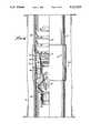
- FIG. 1shows a schematic cross sectional view of one flotation device used to provide buoyant liner or casing forces during running operations
- FIG. 2shows a schematic side view of an alternative embodiment of the flotation device during installation
- FIGS. 3a through 3fshow simplified representations of the alternative device during well completion activities
- FIG. 4shows a side and partial cross sectional view of an air trapping device portion of the engaged assemblage
- FIG. 5shows a side cross-sectional view of another alternative embodiment
- FIG.6is a graphical representation of the results of a test of the flotation device.
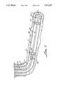
- FIG. 7shows a schematic side view, similar to FIG. 2, of an alternative air annulus embodiment during installation.
- FIG. 1shows a schematic cross-sectional view of one embodiment for running a casing string (or liner or other duct) into a fluid filled bore hole (or cavity) 2.
- a portion of the casing or liner string 4is placed in the top vertical or low angle section of drilled bore hole 2 (lower slanted or high angle portion not shown for clarity).
- the bottom end 3 of liner or casing string 4has a float shoe 5 attached.
- the float shoe 5includes an outwardly or downwardly opening flapper or check valve 6.
- the valve 6prevents inflow of a first or bore fluid 7 during the running or lowering of the string (see downward direction "A" shown on FIG. 1) into the well bore 2.
- the flapper (or ball) of valve 6may be spring or otherwise biased closed to prevent inflow, but allow pressurized fluid outflow (in the downward direction "A"). Outflow occurs if the pressure force within the string 4 can overcome flap seating forces and bore fluid 7 pressure forces.
- a releasable and inflatable bridge plug (or packer) 8is located at the other (second or top) end of a portion of the string to contain air, i.e., to be "floated” in the liquid filled borehole 2.
- the bridge plug 8comprises a cylindrically shaped solid form 9 and an elastomeric bladder (or diaphragm) 10. Pressurizing the bladder 10 through port 11 traps air or other flotation fluid within a flotation cavity 12 below the bridge plug 8 and prevents the entry of third (or non-flotation) fluid 13 from above the bridge plug 8 into cavity 12.
- FIG. 1shows the bladder 10 in a fully inflated position. Inflation is achieved by applying air or other second fluid pressure through open venting ports 15 in stem 14 (source of inflation air is not shown for clarity). Inflation also pressurizes the flotation cavity 12 to prevent collapse of the string under down hole conditions. After inflation, pulling or twisting of stem 14 closes the air venting ports 15 and the source of inflation can be removed.
- the bore fluid 7is normally a single density drilling mud, but may also be a mixture or several layers of different density fluids.
- the various densities within the well boreallow a single flotation cavity 12 to have different buoyant forces at different portions of the well bore proximate to different density bore fluids. This can be highly desirable in extremely high drag well bores or variable incline angle bore portions.
- the distance between the float shoe 5 at one end of the flotation cavity 12 to the bridge plug 8 at the other endis variable to allow control of buoyant forces generated. Repositioning the bridge plug 8 changes the buoyant forces on the "floating" pipe string portion enclosing cavity 12.
- the float shoe 5is installed at the surface before entry of the casing string end into the bore hole 2.
- the length of the flotation cavity or portion of the stringis selected to control the force tending to run the casing into the hole.
- the bridge plug 8seals and is attached to the duct by pressurizing the bladder after installing the length of "floating" pipe string portion into the bore hole 2.
- repositioning the bridge plug when in the holemay also be possible to further adapt and change buoyant forces, if required.
- Thiscan be useful when bending a tubular member through an arced borehole portion (e.g., running a casing through a build section of an extended reach well).
- Buoyant forces in a non-vertical borehole portioncan provide bending forces (e.g., buoyant forces exceed the weight of a buoyed portion of pipe string ahead of a non-buoyed portion in an inclined borehole curving towards a horizontal orientation), and repositioning the bridge plug can adjust these bending forces to adapt to the specific incline/curvature/bending needed.
- the diameter and cross sectional thickness (and associated weight) of the pipe string enclosing cavity 12can be set equal to the weight of the displaced bore fluid 7. This creates a neutral buoyancy so that this "floating" section exerts no upward or downward forces on the walls of the bore hole 2, regardless of orientation or slant. Even if neutral buoyancy is not desired, the controlled effective (buoyed) weight of the selected casing/liner pipe string which must be supported (hung) and any resulting drag during installation operations can be significantly reduced. This reduced maximum effective weight may allow a smaller capacity derrick or rig to be used, or added safety when using a larger one.
- the remainder of the string above the bridge plug 8is fluid filled with a third or heavier fluid 13, such as drilling mud.
- a third or heavier fluid 13such as drilling mud.
- the larger effective weight of the remaining non-flotation portionforces the flotation cavity pipe string portion to the other (i.e., higher incline angle) portions of the well bore 2 (see FIG. 3). These other well portions may be nearly horizontal.
- the non-flotation portionmay extend to the surface, i.e, fill the remainder of the string with the heavier fluid 13.
- string installationmay require a second or multiple floating portions within the string, separated by other bridge plugs 8, especially for deviated hole portions having different angles.
- a retrieving deviceis run on the end of drill pipe and latched on the retrieving stem (or fishing neck) 14.
- the ports 15are opened by the action of the drill pipe latching or twisting onto the retrieving dog on stem 14.
- the ports 15may also be remotely actuated in an alternative embodiment. These opened venting ports 15 allow the higher density fluid 13 to exchange places with the lower density fluid (air) in cavity 12.
- the bridge plug 8is also then deflated by twisting and/or pulling on the retrieving stem 14.
- An alternative embodimentcan separately actuate cavity pressurization/venting and bladder inflation/deflation. Cavity pressurization may not be required if the string can withstand the differential pressure. Fluids (water in this embodiment) used to inflate bladder and pressurize cavity which can also be segregated in this alternative embodiment.
- the fluid flow around and/or through bridge plug 8allows air within the cavity 12 to rise and be vented from within the string 4 at the surface. Fluid flow through plug 8 also allows cavity 12 to be filled with the higher density (or non-flotation) fluid 13. Heavier fluid 13 is typically a drilling mud but may be another fluid having a density greater than the second fluid in cavity 12. After venting, the drill pipe and bridge plug 8 may be removed from the casing 4, and normal cementing operations may commence.
- a restricted float collar 5aserves as a redundant fluid inflow prevention means.
- the restricted float collar 5ais similar in construction to the float shoe 5, including a flapper or check valve 6, and again prevents bore fluid 7 from entering the air-filled cavity.
- the restricted float collar 5ais attached to the pipe interior near the float shoe 5. If the bridge plug is not removed, the restricted float collar 5a attachment and the shape of the interfacing (after the bridge plug slides down) top collar surface and the bottom surface of the bridge plug 8 are designed to grab, preventing interface sliding and rotation during post cementing drilling out operations.
- Alternative embodimentscould also include a restricted float collar 5a in place of (in contrast to redundant with) the float shoe 5 or the addition of a latch-in landing collar 16 (see FIG. 2) near the float collar 5a.
- the float collar 5acan also form a flotation cavity away from the end of the string since it is attached to an interior portion of the string 4, rather than at the end of the string 4.
- FIG. 2shows a schematic side view of another embodiment of an apparatus for floating a portion of a casing or liner string during running.
- a latch-in landing collar 16is attached to the casing or liner string 4 near the float collar/float shoe end (see FIG. 1) of the cavity 12a.
- the latch-in collar 16includes a threaded or latching aperture 17 (shown dotted in FIG. 2 for clarity) which engages a threaded or latching protrusion 18 of an air release plug holder 19 of an air trapping device (or member) 20.
- the piston-like air trapping device 20also includes an air release plug 22 (shown dotted for clarity).
- a first set of (or passage) shear pins 23attaches the release plug 22 to an internal port (or passageway) 24 (shown dotted for clarity) within the plug holder 19.
- a second set of (or plug holder) shear pins 21attaches the plug holder 19 to the liner/casing 4.
- the size and shape of the plug 22 and internal port 24allow the sheared away plug 22 to slide down (direction "A" is towards the well bottom, not necessarily vertically down) toward the protrusion 18.
- the internal port 24is in fluid communication with both the cavity 12a below (through slotted ports 25) and the non-flotation fluid 13 above the translated plug 22.
- the lateral slotted ports 25allow fluid passage to and from the lower portion of the internal port 24 and the cavity 12a (fluid flow shown as a solid and dotted arched arrow).
- the height of plug 22is selected to be less than height of the slotted ports 25, allowing fluid flow in this lower portion.
- a basket 26 near the bottom of the air trapping device 20acts as a retainer of the plug 22 within the internal port 24 when the passage shear pins 23 break and plug 22 moves downward under fluid pressure from above.
- a cement slurryis introduced into the string above the air trapping device 20.
- a bottom wiper plug 27separates the cement slurry above wiper plug 27 from the drilling mud 13 above the air trapping device 20.
- a third set of (or wiper) shear pins 30attaches an inner wiper plug 29 to a wiper plug port 28 (shown dotted) of the wiper plug 27. The inner plug 29 prevents fluid communication above and below the wiper plug 27 until the inner plug 29 moves (i.e., is sheared away) from the plug port 28.
- Each set of shear pinsis selected to rupture at increasingly incremental pressures above normal operating hydrostatic pressure within the string.
- This alternative embodimentuses a (differential) pressure increment of 34 atmospheres (500 psi) to prevent accidental actuation (shearing).
- the first set of shear pins 23rupture at approximately 34 atmospheres (500 psi) over hydrostatic (allowing air to vent and mud to circulate)
- the second set of shear pins 21(allowing the piston-like trapping device to translate) are set at approximately 68 atmospheres (1000 psi) over hydrostatic
- the third set of shear pins 30(allowing cement slurry flow) are set at approximately 102 atmospheres (1500 psi) over hydrostatic.
- FIGS. 3a through 3fshow simplified representations of the alternative apparatus shown in FIG. 2 during well completion activities in the deviated well bore 2.
- the inclined angle "i"angle between the center line of the slanted well portion and the vertical shown in FIG. 3a
- a positive means to prevent fluid inflow to the bottom of the air filled cavityis needed, i.e., float shoe 5.
- Lower incline angle holesmay avoid using a float shoe, depending upon density differences and the lack of fluid miscibility to limit inflow to the flotation portion.
- Large incline angles "i"can also indicate the need for a flotation method of running the casing into the hole.
- FIG. 3ashows the initial apparatus positions after installing the string 4 in the deviated well bore 2.
- the cavity 12aincludes landing collar 16 between the float shoe 5 and air trapping device 20.
- the air release plug 22(shown darkened for clarity) is shear pin attached to air trapping device 20 (see FIG. 2).
- Cavity 12acontains trapped air or other low density fluid, creating buoyancy during the (just completed) insertion of the string portion into the bore hole 2 containing drilling mud 7.
- drilling mud 7is also the non-flotation fluid (see item 13 in FIG. 1) present above the air trapping device 20 in a non-flotation (or high density fluid filled) cavity portion 31.
- the apparatus geometry and mud densitycan be adjusted to control buoyancy and the effective weight of the casing 4 proximate to the cavity 12a.
- FIG. 3bshows the apparatus of FIG. 3a after rupturing the first set of shear pins 23 (see FIG. 2) and movement of the air release plug 22.
- An increased pressure above the air trapping device 20sheared the first set of pins.
- the positions of the elementsare unchanged except for the release plug 22.
- the sheared-away release plug 22may be biased and/or pressure actuated to slide towards the cavity 12a to open ports 25 (see FIG. 2). Opening ports 25 allow fluid communication between the air cavity 12a and non-flotation (i.e., filled with a higher density fluid) cavity portion 31.
- the air from cavity 12amigrates upward in the casing or liner 4 so that it may be then vented at the surface. In wells that have an incline angle of greater than 90 degrees, it may be necessary to positively vent air from cavity 12a. As shown in FIG. 3b , the drilling mud 7 and displaced air form a mud-air interface 32 in the previously weighted cavity 31. The previously buoyant cavity 12a is now full of drilling mud 7.
- Another alternative embodimentcan provide a plurality of internal ports 24 and release plugs 22. This embodiment would assure migration/displacement of fluids in various orientations, e.g., at least one internal port primarily for venting air towards the surface, another for flowing drilling mud into cavity 12a.
- FIG. 3cshows the devices of FIG. 3b after the air (above the mud-air interface shown on FIG. 3b) is vented at the surface (not shown for clarity) and replaced with drilling mud 7. Position of the devices is unchanged, except that drilling mud 7 fills all of the string interior and the annulus between the liner/casing string 4 and well bore 2. Circulation of drilling muds is now possible, if required for hole cleaning or other reasons, without "burps" or "kicks.”
- FIG. 3dshows the devices after installing and pumping a bottom wiper 27 (i.e., a plug wiping the interior surface of the string as it moves) to mate with the air trapping device 20.
- a bottom wiper 27i.e., a plug wiping the interior surface of the string as it moves
- Above the bottom wiper 27is a cement slurry 33.
- Drilling mud 7 within the casing 4 above air trapping device 20has been displaced through passage 24 (See FIG. 2) in the air trapping device 20, landing collar 16, and flapper valve 6 of the float shoe 5 (see FIG. 1).
- a top wiper 34contains the cement slurry 33 between the two sliding and sealing wipers.
- FIG. 3eshows the devices after breaking the second set of shear pins 21 (see FIG. 2) attaching the air trapping device 20 to the casing 4.
- the released air trapping device 20 and bottom wiper 27are shown having been translated to land and latch or threadably engage the landing collar 16, which prevents rotation of the landed assemblage.
- Wiper plug 29contains the cement 33 between the landed assemblage at the landing collar 16 and the top wiper 34.
- the drilling mud 7 previously contained in cavity 12a(see FIG. 3d) has been displaced and flowed though the landing collar 16 and flapper valve 6 of float shoe 5 into the annular space between well bore 2 and casing/liner 4. Displaced drilling mud continues to flow through the float shoe 5 until the top wiper 34 joins the assemblage. Applying another pressure increment tends to shear the third shear pin set 30 (see FIG. 2) holding the wiper plug 29.
- FIG. 3fshows the top wiper plug 34 joined to the assemblage and cement slurry 33 nearly fully displaced out of the string 4 to the annulus between the casing/liner 4 and well bore 2. Shearing and displacing the wiper plug allows the cement to flow through the bottom wiper plug 27 and the slotted ports 25 (see FIG. 2) to the annulus between the casing 4 and well bore 2 through flapper valve 6. The pressurized cement flow also causes the top wiper 34 to slide and contact the bottom wiper plug 27. The cement-mud interface 35 (previously separated by bottom wiper 27) is now in the annulus between the well bore 2 and casing 4. A portion of the cement slurry 33 remains between the assemblage and float shoe 5. This residual cement is drilled out (after setting) in normal post cementing operations (not shown).
- FIG. 4shows a side and partial cross sectional view of the engaged bottom wiper 27 and pinned air trapping device 20 assemblage within a joint in the casing string 4.
- the casing string 4 (shown quarter sectioned) in hole 2is composed of many sections of pipe segments 36 joined by a drift (or piping) collar 37 at each end.
- the piping collar 37is internally threaded to join the external threaded ends of pipe segments 36.
- the illustrated pipe string jointis typical of the string of joined pipe segments.
- An alternative pipe stringcan used without interconnecting pipe segments, avoiding the need for a piping or drift collar 37.
- the piping shownis attached to the air release plug holder 19 portion of the air trapping device 20 (shown in cross section) by the second set of shear pins 21.
- the air trapping device 20also includes a pair of holder O-ring seals 38 forming a fluid tight sliding connection to the interior of the string 4.
- the internal port 24(see FIG. 2) includes an initial threaded portion 39, a cylindrical wiper plug mating portion 40 and a release plug cylindrical portion 41.
- the plug 22was retained by the first set of shear pins 23 (shown sheared in FIG. 4). A pressure differential was applied sufficient to break the plug shear pins 23 and translate the plug 22 to rest against the perforated basket 42 (similar to basket 26 shown in FIG. 2).
- TheTMplug 22also includes a plug O-ring seal 43 which, when plug 22 is pinned in the initial position, formed a fluid tight sliding seal to the plug cylindrical portion 41 of the internal port 24 (see FIG. 2).
- the perforated basket 42catches and prevents further translation or loss of the plug 22. The perforations of basket 42 and ports allow fluids to pass around the displaced plug 22.
- the air trapping device 20also includes a latch protrusion 18 which attaches to the landing collar 16 (see FIG. 3) after the second set of shear pins 21 are broken and the assemblage has been displaced to landing collar 16.
- the protrusion 18 and latch or threaded portion 39prevent rotation of the assemblage (wiper plugs, air trapping device and landing collar) when the assemblage is being drilled out.
- the bottom wiper plug 27(shown in side view for clarity within sectioned casing string 4) includes a series of elastomeric cup shaped wipers 44, an external threaded or latch portion 45 (threadably mating with the internal threaded or latch portion 39 of the air trapping device 20), a pair of elastomeric wiper O-rings 46 (shown darkened for clarity and bearing against the interfacing passageway portion 40), and (hidden from view) an inner plug 29 held in place within wiper port 28 by a third set of shear pins 30 (see FIG. 2).
- An alternative embodimentcan extend the bottom wiper dimensions to positively displace the plug 22 when bottom wiper contacts and mates with air trapping device 20 (see FIG. 2).
- Other types and locations of elastomeric seals, and other mating shapes and dimensionsmay also be provided for other alternative embodiments.
- Solid materials of construction of the air trapping device 20are primarily 6061 aluminum, but various other materials of construction-can be used, as long as they are drillable or otherwise removable.
- the bottom wiper 27acts as a sliding and wiping seal or separator along the interior of the casing.
- the bottom wiper 27separates cement on the upstream side from fluid on the downstream side during certain fluid movements, i.e., slurry cement pumping down-well (direction "A").
- the orientation (right hand engaging) of the external and internal threads shown in FIG. 4are selected to tighten or engage the air trapping device during drilling and prevent unlimited rotation.
- the first advantageis that the present invention avoids the need to use miscible flotation fluids. Air (or any other low density fluid, whether miscible or not) is safely contained and vented to the surface from within the string.
- a second advantage of the present inventionis it avoids the need to remove wiper/plug/insert devices in order to circulate mud or cement slurry. Shear pinned plugged ports open to allow flow for normal circulating, cementing, and drilling out or other operations.
- a third advantageis the translating/latching ability.
- the various componentstranslate and latch together to form a single drillable unit latched to the landing collar.
- the unit or assemblagedoes not rotate or spin with the rotating drill, avoiding drilling difficulties.
- the drillable unit's location at a single known deptheliminates multiple drilling or retrieval operations at various depths.
- the protrusion 18(see FIG. 4) can be designed to include a nesting ability with other air trapping devices 20 which would form the ends of multiple floating segments.
- the protrusion 18would latch into the internal portion 39 of a second (nested) downstream located air trapping device.
- the nested air trapping devicesagain secure multiple segments within an assemblage at a single landing collar for post cementing drilling out procedures.
- a further advantage of this embodimentis the use of existing components, simple fabrication and design.
- the top and bottom wiper plugscan be produced by modifying a commercially available liner wiper plug.
- the use of 6061 aluminumresults in light weight and easily machinable components of the device.
- FIG. 5shows a side cross-sectional view of another alternative embodiment of an air trapping device or an air plug 20a.
- a second set of shear pins 21attaches the air plug 20a to the casing pipe string 4.
- the air plug 20ais similar in construction to a conventional bottom cementing plug.
- the air plug 20aincludes an aluminum insert 48 covered by rubber wipers 44.
- a rupture diaphragm 49separates the flotation cavity 12b, retaining air (or other low density fluid such as nitrogen or light hydrocarbon fluids) from the higher density fluid filled cavity 31a.
- the rupture diaphragm 49replaces the releasable plug 22 and shear pins 23 of this alternative embodiment (see FIG. 2).
- the rupture diaphragm 49has the advantage of simplicity, but may not be capable of withstanding the down hole pressures and forces or be removable without difficulty. Still other alternative embodiments could replace other slidable plugs and inserts with rupture or burst diaphragms.
- wipers 44are slidably attached to the insert 48, another set of shear pins 50 can be used as a redundant means to allow fluid exchange in addition to the rupture diaphragm 49 (allowing fluid exchange even if rupture diaphragm does not rupture).
- FIG. 6is a graphical representation of the results of a test of the flotation method in a deviated underground well bore. The devices and methods used were similar to those shown and described in FIG. 1.
- FIG. 6shows the actual and expected indicator (or slack-off) weight supported during installation of the casing pipe string 4 (see FIG. 1). The string was installed by sections from a derrick at the surface.
- the bore fluid for this examplewas a drilling mud having a density related value of approximately 1137 kilograms/cubic meter (71 pounds/cubic foot).
- the casing usedwas a 95/8 inch (24.45 cm) nominal diameter pipe string.
- the resulting buoyed weight of mud filled casingwas approximately 54.78 newtons/meter (40.4 pounds/foot), whereas the buoyed weight of the air filled cavity portion was 15.73 newtons/meter (11.6 pounds/foot).
- the remaining string portion above the air filled cavitywas filled with drilling mud.
- the actual and flotation expected curve shape(dotted and associated dashed line portion “D"), are similar to, but displaced from, the expected non-flotation curve shape (solid line “B”). This displacement allows the string to be placed to a greater depth (depth increment "E") before the supported weight becomes insufficient to move the string into the bore hole.
- the dotted and dashed curve shape(and ability to install casing or liner) can be altered by changing the number and length of the floated sections as well as by using a flotation fluid other than air or changing the density of the mud in the borehole or the mud above the flotation device.
- the prior art non-flotation method(shown as a solid curve) was expected to produce a larger maximum force (or indicator weight as shown at point "F") to overcome the later developed frictional drag when compared to the flotation method maximum indicator weight (point “G").
- the mud filled sectionsgenerate more drag (shown by the indicator weight declining with depth) than can be overcome by weight (i.e., exceeds critical incline angle). If the particular well included an even higher incline angle section, the decline in indicator weight would be even more severe.
- results of this test exampleshow that flotation of the casing displaced and maintained a controlled margin of supported weight during the entire installation procedure, avoiding a stuck casing.
- resultsalso show that a reduced maximum indicator weight was achieved while allowing a deeper installation and avoiding multiple drilling out procedures.
- FIG. 7shows a schematic side view, similar to FIG. 2, of another alternative embodiment (i.e., an air annulus embodiment) of the apparatus when near the location where the casing is to be set (i.e., one end of a casing string 4 is near the bottom of the wellbore 2).
- the extended reach wellbore 2contains one or more drilling muds 7 having densities greater than air (or other fluid in cavity 12b) and a casing string 4.
- a portion of the casing string 4 and ported packers/retainers 55 and 56forms the exterior surfaces of a modified "flotation" cavity 12b, similar to the cavity 12a shown in FIG. 2.
- the casing string 4also contains drilling mud 7, similar to FIG. 2.
- the pipe string 4has a float shoe 5 and float collar 16 attached proximate to one end of the pipe string similar to FIG. 2, but the ends of the modified cavity 12b within the pipe string 4 are defined by a pair of inflatable packers/retainers 55 and 56, similar to the bridge plug 8 shown in FIG. 1.
- the air annulus embodimentalso contains a conduit 60 forming the interior surface of (i.e., is surrounded by) cavity 12b.
- the conduit 60provides a passageway for fluids from one end of the modified cavity 12b to another (i.e., conduit 60 is attached to ports in the upper inflatable packer 55 and lower cement retainer 56).
- the conduit 60is attached in this embodiment to a surface connecting conduit 61 (typically a string of smaller diameter drill pipe sections) within the remainder of the casing string 4.
- the fluid shown within conduits 60 and 61is drilling mud 7, allowing drilling mud 7 to be circulated during running or other operations, but a cement slurry or other fluid may also be conducted.
- Mud circulationi.e., pumping drilling mud at the surface through the casing string 4, surface connecting string 61, and conduit 60 to the borehole 2 through float collar 16 and float shoe 5 to the annular space between the casing string 4 and borehole 2, then screened or filtered to remove particles (e.g. cuttings or other formation solids) prior to returning to the surface pump) allows lubrication and other fluid properties to assist in the running operations, while the casing string is buoyed within the drilling muds in the borehole 2.
- the surface connecting conduit 61can be run within the casing string 4 to connect with the conduit 60 at an overshot connector 62.
- the surface connecting conduit 61can be pre-assembled and run into the borehole 2 concurrently with the casing string 4.
- a removable plug 63 shown in the conduit 60is optional, provided if needed to prevent drilling mud from flowing in the conduit during portions of the operations when flow is unwanted, such as pressure testing. Removable plug 63 from conduit 60 can be removed by differential pressure.
- This air annulus embodimentspecifically allows flotation and reciprocation of the casing during cementing operations.
- a cement slurrycan be fed through the surface connecting conduit 61 and conduit 60, out through the float collar 16 and float shoe 5 to the annulus between the casing 4 and borehole 2 while reciprocating the casing to obtain improved slurry distribution in the annulus and (after setting) bond strength. Improved distribution helps prevent channeling and other problems.
- the cementing processfirst runs a first portion of the casing 4 (with conduit 60 and packers/retainers 55 & 56) into the borehole 2.
- the cement retainer 56is set and tested (e.g., a test of its integrity against fluid pressure).
- Plug 63i.e. a wire-line plug
- a fittinge.g., an XN nipple
- Packer 55is then inflated and tested.
- Plug 63is then pulled and conduit 60 is filled with mud 7.
- the remaining portions of the casing 4are run in hole while circulating mud 7.
- the surface connecting conduit 61is run in hole, latching and sealing at overshot connector 62 to conduit 60.
- the casing 4is reciprocated (i.e., translated in an oscillating manner along the borehole axis) and drilling mud 7 is circulated until clean (free of filterable solids).
- a cement slurryis then pumped down the surface connecting conduit 61 and conduit 60 while the casing is reciprocated.
- the casingis then located (i.e., landed) and the cement allowed to set.
- Inflatable packer 55can be deflated before or after cement setting, along with the venting of air in cavity 12b and pulling out surface connecting conduit 61, conduit 60, inflatable packers/retainers 55 & 56.
- a similar procedureis used to run, rotate and cement a liner (not shown, but similar to casing 4 shown in FIG. 7).
- the lineris a tubular string to be contained in a lower portion of the borehole 2 and attached or hung from a larger diameter up-hole casing section. At least a first portion of a liner is run into the borehole 2.
- the lower cement retainer 56, plug 63 and upper inflatable packer 55are similarly set and tested in the liner. Plug 63 is removed and the assembly is filled with drilling mud 7 except for cavity 12b.
- the surface connecting conduit 61is similarly latched and sealed to connector 62, followed by running the liner and surface connecting conduit 61 in hole.
- the lineris then rotated (in an oscillating or continuous manner) and drilling mud is circulated clean.
- a cement slurryis pumped down the conduits out to the borehole/liner annulus while the liner continues to be rotated, again improving distribution and bond strength.
- the lineris released (hung on casing), the packer is deflated, and surface connecting conduit (drill pipe), packer(s) and conduit are pulled out.
- a modified air trapping device similar to the device 20 shown in FIG. 2may be used in place of the upper inflatable packer 55.
- the modified deviceincludes another port for connecting to conduit 60.
- conduit 60may be directly connected to a modified float shoe or float collar similar to the shoe 5 and collar 16 shown in FIG. 2.
- a 17.8 cm (7 inch) nominal diameter, 129 newtons (29 pound) nominal weight liner string approximately 1676.4 meters (5,500 feet) longis to be run to 4572 meters (15,000 feet) total measured depth.
- the well path after an initial near vertical section of approximately 304.8 meters (1000 feet)is planned to include a build section where an incline angle build rate of approximately 3.5 degrees per 30.48 meters (100 feet) is maintained until an incline angle of 80.88 degrees is reached at approximately 1009.2 meters (3311 feet) measured depth.
- the incline angle of approximately 80.88 degreesis to be held until a measured depth of 4572 meters (15,000 feet) is reached.
- a 95/8 inch (24.45 cm) nominal diameter casingis planned to extend to 3048 meters (10,000 feet), with an expected friction factor during running of the liner within the casing of 0.35.
- the expected friction factor in the nominal 21.59 cm (81/2 inch) diameter hole extending from 3048 meters (10,000 feet) to 4572 meters (15,000 feet)is 0.50.
- the planned mudhas a density of approximately 1121 kilograms per cubic meter (70 pounds per cubic foot).
- a nominal diameter 6.0325 cm (23/8 inch), 1.814 kilogram 4 pound) tubingi.e., conduit 60 shown in FIG. 7 within the liner, a buoyed weight of approximately 24.40 newtons/meter (18.00 pounds/foot) compared to a flotation cavity 12a (see FIG. 2) within a liner buoyed weight (without tubing) of 33.69 newtons/meter (24.85 pounds/foot).
- a cement retainer on one end, 6.0325 cm (23/8 inch) nominal diameter tubing string between ends and an inflatable packer on the other end of the linercreates an air annulus cavity 12b within the liner.
- a liner tool and tubing overshotare to be screwed onto the liner and drill pipe is then to be used to run the liner to the bottom.
- the drill pipeis expected to be filled with mud at every joint and the liner/drill string rotated until it reaches bottom.
- Rotary torque for this air annulus embodimentis expected to be reduced significantly when compared to running a liner without a flotation cavity (e.g., a torque of approximately 26,000 foot-pounds or 35,251 newton-meters, which is the maximum torque limit of the drill rig planned to be used, is expected to be required at approximately 12,800 feet or 3,901 meters without an air annulus while only approximately 21,000 foot-pounds or 28,472 newton-meters is expected to be required at that depth with an air annulus). This can be especially important if the expected torque without an air annulus is expected to exceed the maximum torque limit of the drill rig, as in this case, and allows and additional 671 meters (2,200 feet) of liner to be run without exceeding the maximum torque limit.
- Still other alternative embodimentsare possible. These include: a plurality of float shoe seals and air trapping plug seals (for seal redundancy); a single shear pin shearing at two points (located across a port or passageway and replacing one or more sets of shear pins); a sensor-actuated releasable latch or other releasable device to attach each plug to each passageway (replacing shear pins); placement of cylindrical or otherwise ported solid inserts (e.g., foam) or higher density fluid into the flotation cavity 12 in addition to lower density (flotation) fluids (to improve the control of buoyant forces); combining the float shoe, float collar, and/or the landing collar in a single component; combining centralizing (outward radial) protrusions on the string (to create a string stand off annulus within the well bore) with multiple trapping devices at pipe joints; replacing the float shoe valve with a float type trap or other back-flow preventer; and having translating components, conduits, and
- a still further alternative embodimentis to make portions of the devices such as plugs from materials which are dissolvable, thermally degradable or fluid reactive/decomposing (avoiding pressure increments or drilling out procedures). Although no longer required, lubricants can also be used in conjunction with these flotation methods and devices to further control or reduce the running coefficient of friction.
- flotation devices and methodssatisfy the need for a simple method to run a casing or liner string in a long horizontal well bore. Portions of the string are "floated" in the well bore fluids by providing one or more plugged buoyant cavities.
- opening a circulation and cementing pathcan be accomplished by a simple increase-in pressure and translation of insert/plug devices without entirely removing the devices. This embodiment also allows circulation during buoyant operations and reciprocating/rotation during cementing. Devices are finally removed by normal post-cementing drilling out techniques, avoiding the need for a separate removal step.
- the use of air and lightweight materialsminimizes storage and other related requirements.
- the present inventionalso reduces the maximum capability of the drill rig needed to accomplish the setting of the casing/liner string and extended reach well could theoretically have an infinite length (i.e., total measured depth) if flotation cavity sections are at neutral buoyancy. More typically, the invention provides major advantages for higher than critical incline angle (e.g., nearly horizontal) well portions (to be lined or cased) of at least 914 meters (3,000 feet) in length , more preferably at least 1524 meters (5,000 feet), and still more preferably at least 1828 meters (6,000 feet) in length.
- the buoyancy forcesalso allow a high build rate, limited only by the flexibility of the liner or casing tubular members.
- the buoyant forcescan theoretically provide a bending force without scraping (and possibly damaging or excessively opening) the build portion of the wellbore. More typically, the invention provides major advantages for build rates of at least approximately 2.0 degrees per 30.48 meters (100 feet), more preferably a build rate of at least approximately 3.5 degrees per 30.48 meters (100 feet). Further advantages of the device include: increased safety (avoiding large casing running loads at the drilling platform), reliability (reducing the likelihood of stuck casing), maintenance (single use, drillable components), efficiency (full flow production/injection capability), and reduced cost (no separate removal step or need to recover items from great depth).
- a hydraulic release oil toolwhich may be used advantageously with the present invention is disclosed in U.S. patent application Ser. No. 07/418,510, filed on Oct. 9, 1990, the teachings which are incorporated in their entirety by reference.
- the release toolmay be used to removably attach a drill string to a liner having a flotation cavity and being run into an extended reach wellbore.
- the release toolallows bidirectional rotation and high torque, combined with ease of release and removal.
Landscapes
- Life Sciences & Earth Sciences (AREA)
- Engineering & Computer Science (AREA)
- Geology (AREA)
- Mining & Mineral Resources (AREA)
- Physics & Mathematics (AREA)
- Environmental & Geological Engineering (AREA)
- Fluid Mechanics (AREA)
- General Life Sciences & Earth Sciences (AREA)
- Geochemistry & Mineralogy (AREA)
- Marine Sciences & Fisheries (AREA)
- Earth Drilling (AREA)
Abstract
Description
Claims (67)
Priority Applications (8)
| Application Number | Priority Date | Filing Date | Title |
|---|---|---|---|
| US07/569,691US5117915A (en) | 1989-08-31 | 1990-08-22 | Well casing flotation device and method |
| IE311490AIE903114A1 (en) | 1989-08-31 | 1990-08-28 | Well casing flotation device and method |
| MYPI90001467AMY106026A (en) | 1989-08-31 | 1990-08-28 | Well casing flotation device and method |
| OA59849AOA09261A (en) | 1989-08-31 | 1990-08-30 | Well casing flotation device and method. |
| CN90108377ACN1053278A (en) | 1989-08-31 | 1990-08-31 | Well casing flotation device and method |
| TR90/0805ATR24700A (en) | 1989-08-31 | 1990-09-19 | WELL DRILLING ENVELOPE YUEZDUERME DEVICE AND YOENTEM |
| US07/693,352US5174375A (en) | 1989-10-10 | 1991-04-30 | Hydraulic release system |
| US07/820,997US5181571A (en) | 1989-08-31 | 1992-02-10 | Well casing flotation device and method |
Applications Claiming Priority (4)
| Application Number | Priority Date | Filing Date | Title |
|---|---|---|---|
| US07/401,086US4986361A (en) | 1989-08-31 | 1989-08-31 | Well casing flotation device and method |
| US48631290A | 1990-02-28 | 1990-02-28 | |
| US07/560,389US5113411A (en) | 1989-07-31 | 1990-07-31 | Modulator and demodulator for data transmission systems |
| US07/569,691US5117915A (en) | 1989-08-31 | 1990-08-22 | Well casing flotation device and method |
Related Parent Applications (3)
| Application Number | Title | Priority Date | Filing Date |
|---|---|---|---|
| US07/401,086Continuation-In-PartUS4986361A (en) | 1989-08-31 | 1989-08-31 | Well casing flotation device and method |
| US48631290AContinuation-In-Part | 1989-08-31 | 1990-02-28 | |
| US07/560,389Continuation-In-PartUS5113411A (en) | 1989-07-31 | 1990-07-31 | Modulator and demodulator for data transmission systems |
Related Child Applications (2)
| Application Number | Title | Priority Date | Filing Date |
|---|---|---|---|
| US07/693,352Continuation-In-PartUS5174375A (en) | 1989-10-10 | 1991-04-30 | Hydraulic release system |
| US07/820,997ContinuationUS5181571A (en) | 1989-08-31 | 1992-02-10 | Well casing flotation device and method |
Publications (1)
| Publication Number | Publication Date |
|---|---|
| US5117915Atrue US5117915A (en) | 1992-06-02 |
Family
ID=27503459
Family Applications (1)
| Application Number | Title | Priority Date | Filing Date |
|---|---|---|---|
| US07/569,691Expired - LifetimeUS5117915A (en) | 1989-08-31 | 1990-08-22 | Well casing flotation device and method |
Country Status (1)
| Country | Link |
|---|---|
| US (1) | US5117915A (en) |
Cited By (118)
| Publication number | Priority date | Publication date | Assignee | Title |
|---|---|---|---|---|
| US5242025A (en)* | 1992-06-30 | 1993-09-07 | Union Oil Company Of California | Guided oscillatory well path drilling by seismic imaging |
| US5553667A (en)* | 1995-04-26 | 1996-09-10 | Weatherford U.S., Inc. | Cementing system |
| US5553671A (en)* | 1994-02-25 | 1996-09-10 | Sieber; Bobby G. | Piston sub for isolating drilling fluids from hydraulic fluids |
| US5613561A (en)* | 1995-07-27 | 1997-03-25 | Schlumberger Technology Corporation | Apparatus for sealing instruments in a downhole tool |
| EP0846839A2 (en) | 1996-11-12 | 1998-06-10 | Halliburton Energy Services, Inc. | Method and apparatus for placing and cementing casing in horizontal wells |
| US6056053A (en)* | 1995-04-26 | 2000-05-02 | Weatherford/Lamb, Inc. | Cementing systems for wellbores |
| US6082451A (en)* | 1995-04-26 | 2000-07-04 | Weatherford/Lamb, Inc. | Wellbore shoe joints and cementing systems |
| EP1184536A2 (en) | 2000-08-31 | 2002-03-06 | Halliburton Energy Services, Inc. | Method and apparatus for installing casing in a well |
| WO2002061237A1 (en)* | 2001-01-30 | 2002-08-08 | Petróleo Brasileiro S.A. - Petrobras | Methods and mechanisms to set a hollow device into and to retrieve said hollow device from a flow pipe |
| US6622798B1 (en) | 2002-05-08 | 2003-09-23 | Halliburton Energy Services, Inc. | Method and apparatus for maintaining a fluid column in a wellbore annulus |
| US6634430B2 (en) | 2001-12-20 | 2003-10-21 | Exxonmobil Upstream Research Company | Method for installation of evacuated tubular conduits |
| US6708770B2 (en) | 2000-06-30 | 2004-03-23 | Bj Services Company | Drillable bridge plug |
| EP1358426A4 (en)* | 2001-02-07 | 2005-05-04 | Petroleo Brasileiro Sa | Method of diminishing the size of the cross section of an opening of a hollow device located in a flow pipe |
| AT500192A1 (en)* | 1995-06-07 | 2005-11-15 | Guilford Pharm Inc | NON-IMMUNOSUPPRESSIVE COMPOUND, PHARMACEUTICAL MASS CONTAINING THE SAME, AND METHOD FOR PRODUCING THE COMPOUND |
| AT500193A1 (en)* | 1995-06-07 | 2005-11-15 | Guilford Pharm Inc | Rotamase inhibiting N-glyoxyl prolyl ester derivs. - are useful for stimulating growth of damaged nerves and treating neurological disorders |
| US20050257936A1 (en)* | 2004-05-07 | 2005-11-24 | Bj Services Company | Gravity valve for a downhole tool |
| US20060062638A1 (en)* | 2004-09-22 | 2006-03-23 | Bergeron Billy J | Floatation module and method |
| WO2006101606A3 (en)* | 2005-03-22 | 2007-01-04 | Exxonmobil Upstream Res Co | Method for running tubulars in wellbores |
| US20070023192A1 (en)* | 2005-03-21 | 2007-02-01 | Bbj Tools Inc. | Method and tool for placing a well bore liner |
| US20070102165A1 (en)* | 2005-11-10 | 2007-05-10 | Bj Services Company | Self centralizing non-rotational slip and cone system for downhole tools |
| US20070119600A1 (en)* | 2000-06-30 | 2007-05-31 | Gabriel Slup | Drillable bridge plug |
| US7255178B2 (en) | 2000-06-30 | 2007-08-14 | Bj Services Company | Drillable bridge plug |
| US20070295513A1 (en)* | 2004-12-10 | 2007-12-27 | Biegler Mark W | Tubular Flotation With Pressurized Fluid |
| US20080245528A1 (en)* | 2005-09-15 | 2008-10-09 | Petroleum Technology Company As | Separating Device |
| US7909096B2 (en) | 2007-03-02 | 2011-03-22 | Schlumberger Technology Corporation | Method and apparatus of reservoir stimulation while running casing |
| US20110132143A1 (en)* | 2002-12-08 | 2011-06-09 | Zhiyue Xu | Nanomatrix powder metal compact |
| US20110132612A1 (en)* | 2009-12-08 | 2011-06-09 | Baker Hughes Incorporated | Telescopic Unit with Dissolvable Barrier |
| US20110214881A1 (en)* | 2010-03-05 | 2011-09-08 | Baker Hughes Incorporated | Flow control arrangement and method |
| US8079413B2 (en) | 2008-12-23 | 2011-12-20 | W. Lynn Frazier | Bottom set downhole plug |
| US8146667B2 (en)* | 2010-07-19 | 2012-04-03 | Marc Moszkowski | Dual gradient pipeline evacuation method |
| CN102650203A (en)* | 2012-05-17 | 2012-08-29 | 安徽省煤田地质局第一勘探队 | Buoyant valve and self-balancing arrangement method for valve-contained operation sleeve for gas pumping hole |
| CN102720526A (en)* | 2012-06-08 | 2012-10-10 | 安徽省煤田地质局第一勘探队 | Double-plug piping method of heavy-caliber gas exhaust hole working sleeve |
| US8307892B2 (en) | 2009-04-21 | 2012-11-13 | Frazier W Lynn | Configurable inserts for downhole plugs |
| US8327931B2 (en) | 2009-12-08 | 2012-12-11 | Baker Hughes Incorporated | Multi-component disappearing tripping ball and method for making the same |
| CN102937012A (en)* | 2012-11-03 | 2013-02-20 | 安徽理工大学 | Cement buoyant valve in gas pumping hole working sleeve and manufacture method thereof |
| US8425651B2 (en) | 2010-07-30 | 2013-04-23 | Baker Hughes Incorporated | Nanomatrix metal composite |
| US8496052B2 (en) | 2008-12-23 | 2013-07-30 | Magnum Oil Tools International, Ltd. | Bottom set down hole tool |
| US8573295B2 (en) | 2010-11-16 | 2013-11-05 | Baker Hughes Incorporated | Plug and method of unplugging a seat |
| USD694280S1 (en) | 2011-07-29 | 2013-11-26 | W. Lynn Frazier | Configurable insert for a downhole plug |
| USD694281S1 (en) | 2011-07-29 | 2013-11-26 | W. Lynn Frazier | Lower set insert with a lower ball seat for a downhole plug |
| US8631876B2 (en) | 2011-04-28 | 2014-01-21 | Baker Hughes Incorporated | Method of making and using a functionally gradient composite tool |
| USD698370S1 (en) | 2011-07-29 | 2014-01-28 | W. Lynn Frazier | Lower set caged ball insert for a downhole plug |
| USD703713S1 (en) | 2011-07-29 | 2014-04-29 | W. Lynn Frazier | Configurable caged ball insert for a downhole tool |
| US20140131045A1 (en)* | 2012-11-14 | 2014-05-15 | Schlumberger Technology Corporation | Downhole Tool Positioning System And Method |
| US8776884B2 (en) | 2010-08-09 | 2014-07-15 | Baker Hughes Incorporated | Formation treatment system and method |
| US8783365B2 (en) | 2011-07-28 | 2014-07-22 | Baker Hughes Incorporated | Selective hydraulic fracturing tool and method thereof |
| US20140224807A1 (en)* | 2013-02-11 | 2014-08-14 | Baker Hughes Incorporated | Removable plug arrangement and method of removing a plug arrangement |
| US8899317B2 (en) | 2008-12-23 | 2014-12-02 | W. Lynn Frazier | Decomposable pumpdown ball for downhole plugs |
| US20140352976A1 (en)* | 2012-01-30 | 2014-12-04 | Altus Intervention As | Method And An Apparatus For Retrieving A Tubing From A Well |
| EP2813669A1 (en)* | 2013-06-14 | 2014-12-17 | Welltec A/S | A completion method and a downhole system |
| US20150114656A1 (en)* | 2012-08-28 | 2015-04-30 | Halliburton Energy Services, Inc. | Riser displacement and cleaning systems and methods of use |
| US9022107B2 (en) | 2009-12-08 | 2015-05-05 | Baker Hughes Incorporated | Dissolvable tool |
| US9033055B2 (en) | 2011-08-17 | 2015-05-19 | Baker Hughes Incorporated | Selectively degradable passage restriction and method |
| US9057242B2 (en) | 2011-08-05 | 2015-06-16 | Baker Hughes Incorporated | Method of controlling corrosion rate in downhole article, and downhole article having controlled corrosion rate |
| US9068428B2 (en) | 2012-02-13 | 2015-06-30 | Baker Hughes Incorporated | Selectively corrodible downhole article and method of use |
| US9079246B2 (en) | 2009-12-08 | 2015-07-14 | Baker Hughes Incorporated | Method of making a nanomatrix powder metal compact |
| US9080098B2 (en) | 2011-04-28 | 2015-07-14 | Baker Hughes Incorporated | Functionally gradient composite article |
| US9090956B2 (en) | 2011-08-30 | 2015-07-28 | Baker Hughes Incorporated | Aluminum alloy powder metal compact |
| US9090955B2 (en) | 2010-10-27 | 2015-07-28 | Baker Hughes Incorporated | Nanomatrix powder metal composite |
| US9109269B2 (en) | 2011-08-30 | 2015-08-18 | Baker Hughes Incorporated | Magnesium alloy powder metal compact |
| US9109428B2 (en) | 2009-04-21 | 2015-08-18 | W. Lynn Frazier | Configurable bridge plugs and methods for using same |
| US9109429B2 (en) | 2002-12-08 | 2015-08-18 | Baker Hughes Incorporated | Engineered powder compact composite material |
| US9127515B2 (en) | 2010-10-27 | 2015-09-08 | Baker Hughes Incorporated | Nanomatrix carbon composite |
| US9127527B2 (en) | 2009-04-21 | 2015-09-08 | W. Lynn Frazier | Decomposable impediments for downhole tools and methods for using same |
| US9133695B2 (en) | 2011-09-03 | 2015-09-15 | Baker Hughes Incorporated | Degradable shaped charge and perforating gun system |
| US9139928B2 (en) | 2011-06-17 | 2015-09-22 | Baker Hughes Incorporated | Corrodible downhole article and method of removing the article from downhole environment |
| US9163477B2 (en) | 2009-04-21 | 2015-10-20 | W. Lynn Frazier | Configurable downhole tools and methods for using same |
| US9181772B2 (en) | 2009-04-21 | 2015-11-10 | W. Lynn Frazier | Decomposable impediments for downhole plugs |
| US9187990B2 (en) | 2011-09-03 | 2015-11-17 | Baker Hughes Incorporated | Method of using a degradable shaped charge and perforating gun system |
| US9217319B2 (en) | 2012-05-18 | 2015-12-22 | Frazier Technologies, L.L.C. | High-molecular-weight polyglycolides for hydrocarbon recovery |
| US9227243B2 (en) | 2009-12-08 | 2016-01-05 | Baker Hughes Incorporated | Method of making a powder metal compact |
| US9243475B2 (en) | 2009-12-08 | 2016-01-26 | Baker Hughes Incorporated | Extruded powder metal compact |
| US9267347B2 (en) | 2009-12-08 | 2016-02-23 | Baker Huges Incorporated | Dissolvable tool |
| US9279295B2 (en) | 2012-06-28 | 2016-03-08 | Weatherford Technology Holdings, Llc | Liner flotation system |
| US9284812B2 (en) | 2011-11-21 | 2016-03-15 | Baker Hughes Incorporated | System for increasing swelling efficiency |
| US9347119B2 (en) | 2011-09-03 | 2016-05-24 | Baker Hughes Incorporated | Degradable high shock impedance material |
| USRE46028E1 (en) | 2003-05-15 | 2016-06-14 | Kureha Corporation | Method and apparatus for delayed flow or pressure change in wells |
| US9506309B2 (en) | 2008-12-23 | 2016-11-29 | Frazier Ball Invention, LLC | Downhole tools having non-toxic degradable elements |
| US9562415B2 (en) | 2009-04-21 | 2017-02-07 | Magnum Oil Tools International, Ltd. | Configurable inserts for downhole plugs |
| US9587475B2 (en) | 2008-12-23 | 2017-03-07 | Frazier Ball Invention, LLC | Downhole tools having non-toxic degradable elements and their methods of use |
| US9605508B2 (en) | 2012-05-08 | 2017-03-28 | Baker Hughes Incorporated | Disintegrable and conformable metallic seal, and method of making the same |
| US9643144B2 (en) | 2011-09-02 | 2017-05-09 | Baker Hughes Incorporated | Method to generate and disperse nanostructures in a composite material |
| US9643250B2 (en) | 2011-07-29 | 2017-05-09 | Baker Hughes Incorporated | Method of controlling the corrosion rate of alloy particles, alloy particle with controlled corrosion rate, and articles comprising the particle |
| US9682425B2 (en) | 2009-12-08 | 2017-06-20 | Baker Hughes Incorporated | Coated metallic powder and method of making the same |
| US9708878B2 (en) | 2003-05-15 | 2017-07-18 | Kureha Corporation | Applications of degradable polymer for delayed mechanical changes in wells |
| US9707739B2 (en) | 2011-07-22 | 2017-07-18 | Baker Hughes Incorporated | Intermetallic metallic composite, method of manufacture thereof and articles comprising the same |
| US9816339B2 (en) | 2013-09-03 | 2017-11-14 | Baker Hughes, A Ge Company, Llc | Plug reception assembly and method of reducing restriction in a borehole |
| US9833838B2 (en) | 2011-07-29 | 2017-12-05 | Baker Hughes, A Ge Company, Llc | Method of controlling the corrosion rate of alloy particles, alloy particle with controlled corrosion rate, and articles comprising the particle |
| US9856547B2 (en) | 2011-08-30 | 2018-01-02 | Bakers Hughes, A Ge Company, Llc | Nanostructured powder metal compact |
| US9910026B2 (en) | 2015-01-21 | 2018-03-06 | Baker Hughes, A Ge Company, Llc | High temperature tracers for downhole detection of produced water |
| US9908594B2 (en) | 2016-04-29 | 2018-03-06 | Expert E&P Consultants, L.L.C. | Flotation system and method |
| US20180080308A1 (en)* | 2016-09-22 | 2018-03-22 | Klx Inc. | Apparatus and method for running casing in a wellbore |
| US9926766B2 (en) | 2012-01-25 | 2018-03-27 | Baker Hughes, A Ge Company, Llc | Seat for a tubular treating system |
| AU2016203183B2 (en)* | 2015-05-15 | 2018-03-29 | Schlumberger Technology B.V. | A Buoyancy assist tool |
| US20180112488A1 (en)* | 2016-10-26 | 2018-04-26 | Weatherford Technology Holdings, Llc | Casing floatation system with latch-in-plugs |
| US10016810B2 (en) | 2015-12-14 | 2018-07-10 | Baker Hughes, A Ge Company, Llc | Methods of manufacturing degradable tools using a galvanic carrier and tools manufactured thereof |
| US10167677B2 (en) | 2016-04-29 | 2019-01-01 | William von Eberstein | Flotation system and method |
| US10221637B2 (en) | 2015-08-11 | 2019-03-05 | Baker Hughes, A Ge Company, Llc | Methods of manufacturing dissolvable tools via liquid-solid state molding |
| US10240419B2 (en) | 2009-12-08 | 2019-03-26 | Baker Hughes, A Ge Company, Llc | Downhole flow inhibition tool and method of unplugging a seat |
| WO2019139679A1 (en)* | 2018-01-15 | 2019-07-18 | Baker Hughes, A Ge Company, Llc | Shoe isolation system and method for isolating a shoe |
| US10378303B2 (en) | 2015-03-05 | 2019-08-13 | Baker Hughes, A Ge Company, Llc | Downhole tool and method of forming the same |
| US10871053B2 (en) | 2007-12-03 | 2020-12-22 | Magnum Oil Tools International, Ltd. | Downhole assembly for selectively sealing off a wellbore |
| US10883315B2 (en) | 2013-02-05 | 2021-01-05 | Ncs Multistage Inc. | Casing float tool |
| US10954740B2 (en) | 2016-10-26 | 2021-03-23 | Weatherford Netherlands, B.V. | Top plug with transitionable seal |
| CN113090224A (en)* | 2019-12-23 | 2021-07-09 | 中国石油天然气股份有限公司 | Guide shoe for well cementation and expansion suspension well cementation tubular column |
| US11125044B2 (en) | 2019-03-06 | 2021-09-21 | Saudi Arabian Oil Company | Pressurized flotation for tubular installation in wellbores |
| US11167343B2 (en) | 2014-02-21 | 2021-11-09 | Terves, Llc | Galvanically-active in situ formed particles for controlled rate dissolving tools |
| US11365164B2 (en) | 2014-02-21 | 2022-06-21 | Terves, Llc | Fluid activated disintegrating metal system |
| US20220333458A1 (en)* | 2021-04-15 | 2022-10-20 | Canadian Casing Accessories Inc. | Modified casing buoyancy system and methods of use |
| US11530582B2 (en) | 2021-04-30 | 2022-12-20 | Saudi Arabian Oil Company | Casing strings and related methods of deployment in horizontal wells |
| US11649526B2 (en) | 2017-07-27 | 2023-05-16 | Terves, Llc | Degradable metal matrix composite |
| US20230203893A1 (en)* | 2021-12-28 | 2023-06-29 | Baker Hughes Oilfield Operations Llc | Liner/casing buoyancy arrangement, method and system |
| US11713649B2 (en) | 2020-02-20 | 2023-08-01 | Nine Downhole Technologies, Llc | Plugging device |
| US11761289B2 (en) | 2020-05-04 | 2023-09-19 | Nine Downhole Technologies, Llc | Shearable sleeve |
| US12018356B2 (en) | 2014-04-18 | 2024-06-25 | Terves Inc. | Galvanically-active in situ formed particles for controlled rate dissolving tools |
| US12055000B2 (en) | 2021-12-28 | 2024-08-06 | Baker Hughes Oilfield Operations Llc | Liner/casing buoyancy arrangement, method and system |
| US12055010B2 (en) | 2022-08-04 | 2024-08-06 | Weatherford Technology Holdings, Llc | Method of cementing casing using shoe track having displaceable valve component |
| US12060771B2 (en) | 2022-08-08 | 2024-08-13 | Saudi Arabian Oil Company | Downhole clean out tool |
Citations (13)
| Publication number | Priority date | Publication date | Assignee | Title |
|---|---|---|---|---|
| US2698054A (en)* | 1949-01-31 | 1954-12-28 | Brown | Method of and apparatus for lowering pipe within a well bore |
| US3526280A (en)* | 1967-10-17 | 1970-09-01 | Halliburton Co | Method for flotation completion for highly deviated wells |
| US3572432A (en)* | 1969-09-25 | 1971-03-23 | Halliburton Co | Apparatus for flotation completion for highly deviated wells |
| SU547526A1 (en)* | 1970-01-08 | 1977-02-25 | Всесоюзный Научно-Исследовательский И Проектно-Конструкторский Институт По Осушению Месторождений Полезных Ископаемых,Специальным Горным Работам, Рудничной Геологии И Маркшейдерскому Делу | The way the casing in the casing |
| US4308917A (en)* | 1978-01-09 | 1982-01-05 | Dismukes Newton B | Buoyant tubulars and method for installing same in a well bore |
| DE3021558A1 (en)* | 1980-06-07 | 1982-01-07 | Rheinische Braunkohlenwerke AG, 5000 Köln | Borehole tube string installation - using barrier discs for temporary retention of float fillings |
| US4384616A (en)* | 1980-11-28 | 1983-05-24 | Mobil Oil Corporation | Method of placing pipe into deviated boreholes |
| US4396211A (en)* | 1981-06-10 | 1983-08-02 | Baker International Corporation | Insulating tubular conduit apparatus and method |
| US4484641A (en)* | 1981-05-21 | 1984-11-27 | Dismukes Newton B | Tubulars for curved bore holes |
| US4589495A (en)* | 1984-04-19 | 1986-05-20 | Weatherford U.S., Inc. | Apparatus and method for inserting flow control means into a well casing |
| EP0186317A1 (en)* | 1984-12-06 | 1986-07-02 | Mobil Oil Corporation | Casing high angle wellbores |
| US4683955A (en)* | 1986-04-30 | 1987-08-04 | Halliburton Company | Automatic fill-up floating apparatus |
| US4986361A (en)* | 1989-08-31 | 1991-01-22 | Union Oil Company Of California | Well casing flotation device and method |
- 1990
- 1990-08-22USUS07/569,691patent/US5117915A/ennot_activeExpired - Lifetime
Patent Citations (13)
| Publication number | Priority date | Publication date | Assignee | Title |
|---|---|---|---|---|
| US2698054A (en)* | 1949-01-31 | 1954-12-28 | Brown | Method of and apparatus for lowering pipe within a well bore |
| US3526280A (en)* | 1967-10-17 | 1970-09-01 | Halliburton Co | Method for flotation completion for highly deviated wells |
| US3572432A (en)* | 1969-09-25 | 1971-03-23 | Halliburton Co | Apparatus for flotation completion for highly deviated wells |
| SU547526A1 (en)* | 1970-01-08 | 1977-02-25 | Всесоюзный Научно-Исследовательский И Проектно-Конструкторский Институт По Осушению Месторождений Полезных Ископаемых,Специальным Горным Работам, Рудничной Геологии И Маркшейдерскому Делу | The way the casing in the casing |
| US4308917A (en)* | 1978-01-09 | 1982-01-05 | Dismukes Newton B | Buoyant tubulars and method for installing same in a well bore |
| DE3021558A1 (en)* | 1980-06-07 | 1982-01-07 | Rheinische Braunkohlenwerke AG, 5000 Köln | Borehole tube string installation - using barrier discs for temporary retention of float fillings |
| US4384616A (en)* | 1980-11-28 | 1983-05-24 | Mobil Oil Corporation | Method of placing pipe into deviated boreholes |
| US4484641A (en)* | 1981-05-21 | 1984-11-27 | Dismukes Newton B | Tubulars for curved bore holes |
| US4396211A (en)* | 1981-06-10 | 1983-08-02 | Baker International Corporation | Insulating tubular conduit apparatus and method |
| US4589495A (en)* | 1984-04-19 | 1986-05-20 | Weatherford U.S., Inc. | Apparatus and method for inserting flow control means into a well casing |
| EP0186317A1 (en)* | 1984-12-06 | 1986-07-02 | Mobil Oil Corporation | Casing high angle wellbores |
| US4683955A (en)* | 1986-04-30 | 1987-08-04 | Halliburton Company | Automatic fill-up floating apparatus |
| US4986361A (en)* | 1989-08-31 | 1991-01-22 | Union Oil Company Of California | Well casing flotation device and method |
Non-Patent Citations (4)
| Title |
|---|
| "Extended Reach Drilling From Platform Irene", by Mueller et al., OTC #6224, Presented at 22nd Annual Offshore Technology Conference, May 7-10, 1990. |
| "Mobil Identifies Extended-Reach-Drilling Advantages, Possiblities in North Sea" by Tolle et al., Presentation of Off shore Northern Seas Conf., 1985. |
| Extended Reach Drilling From Platform Irene , by Mueller et al., OTC 6224, Presented at 22nd Annual Offshore Technology Conference, May 7 10, 1990.* |
| Mobil Identifies Extended Reach Drilling Advantages, Possiblities in North Sea by Tolle et al., Presentation of Off shore Northern Seas Conf., 1985.* |
Cited By (176)
| Publication number | Priority date | Publication date | Assignee | Title |
|---|---|---|---|---|
| US5242025A (en)* | 1992-06-30 | 1993-09-07 | Union Oil Company Of California | Guided oscillatory well path drilling by seismic imaging |
| US5553671A (en)* | 1994-02-25 | 1996-09-10 | Sieber; Bobby G. | Piston sub for isolating drilling fluids from hydraulic fluids |
| US5553667A (en)* | 1995-04-26 | 1996-09-10 | Weatherford U.S., Inc. | Cementing system |
| US5813457A (en)* | 1995-04-26 | 1998-09-29 | Weatherford/Lamb, Inc. | Wellbore cementing system |
| US6056053A (en)* | 1995-04-26 | 2000-05-02 | Weatherford/Lamb, Inc. | Cementing systems for wellbores |
| US6082451A (en)* | 1995-04-26 | 2000-07-04 | Weatherford/Lamb, Inc. | Wellbore shoe joints and cementing systems |
| AT500192A1 (en)* | 1995-06-07 | 2005-11-15 | Guilford Pharm Inc | NON-IMMUNOSUPPRESSIVE COMPOUND, PHARMACEUTICAL MASS CONTAINING THE SAME, AND METHOD FOR PRODUCING THE COMPOUND |
| AT500193A1 (en)* | 1995-06-07 | 2005-11-15 | Guilford Pharm Inc | Rotamase inhibiting N-glyoxyl prolyl ester derivs. - are useful for stimulating growth of damaged nerves and treating neurological disorders |
| US5613561A (en)* | 1995-07-27 | 1997-03-25 | Schlumberger Technology Corporation | Apparatus for sealing instruments in a downhole tool |
| US5829526A (en)* | 1996-11-12 | 1998-11-03 | Halliburton Energy Services, Inc. | Method and apparatus for placing and cementing casing in horizontal wells |
| EP0846839A2 (en) | 1996-11-12 | 1998-06-10 | Halliburton Energy Services, Inc. | Method and apparatus for placing and cementing casing in horizontal wells |
| US7600572B2 (en) | 2000-06-30 | 2009-10-13 | Bj Services Company | Drillable bridge plug |
| US7255178B2 (en) | 2000-06-30 | 2007-08-14 | Bj Services Company | Drillable bridge plug |
| US20070119600A1 (en)* | 2000-06-30 | 2007-05-31 | Gabriel Slup | Drillable bridge plug |
| US6708770B2 (en) | 2000-06-30 | 2004-03-23 | Bj Services Company | Drillable bridge plug |
| US6758281B2 (en) | 2000-08-31 | 2004-07-06 | Halliburton Energy Services, Inc. | Methods and apparatus for creating a downhole buoyant casing chamber |
| US6651748B2 (en) | 2000-08-31 | 2003-11-25 | Halliburton Energy Services, Inc. | Methods and apparatus for creating a downhole buoyant casing chamber |
| EP1184536A2 (en) | 2000-08-31 | 2002-03-06 | Halliburton Energy Services, Inc. | Method and apparatus for installing casing in a well |
| US6505685B1 (en) | 2000-08-31 | 2003-01-14 | Halliburton Energy Services, Inc. | Methods and apparatus for creating a downhole buoyant casing chamber |
| US6678954B2 (en) | 2001-01-30 | 2004-01-20 | Petroleo Brasileiro S.A. - Petrobras | Methods to set a hollow device into and to retrieve said hollow device from a flow pipe |
| WO2002061237A1 (en)* | 2001-01-30 | 2002-08-08 | Petróleo Brasileiro S.A. - Petrobras | Methods and mechanisms to set a hollow device into and to retrieve said hollow device from a flow pipe |
| EP1358426A4 (en)* | 2001-02-07 | 2005-05-04 | Petroleo Brasileiro Sa | Method of diminishing the size of the cross section of an opening of a hollow device located in a flow pipe |
| US6634430B2 (en) | 2001-12-20 | 2003-10-21 | Exxonmobil Upstream Research Company | Method for installation of evacuated tubular conduits |
| EP1361334A1 (en) | 2002-05-08 | 2003-11-12 | Halliburton Energy Services, Inc. | Method and apparatus for maintaining a fluid column in a wellbore annulus |
| US6622798B1 (en) | 2002-05-08 | 2003-09-23 | Halliburton Energy Services, Inc. | Method and apparatus for maintaining a fluid column in a wellbore annulus |
| US9109429B2 (en) | 2002-12-08 | 2015-08-18 | Baker Hughes Incorporated | Engineered powder compact composite material |
| US9101978B2 (en) | 2002-12-08 | 2015-08-11 | Baker Hughes Incorporated | Nanomatrix powder metal compact |
| US20110132143A1 (en)* | 2002-12-08 | 2011-06-09 | Zhiyue Xu | Nanomatrix powder metal compact |
| USRE46028E1 (en) | 2003-05-15 | 2016-06-14 | Kureha Corporation | Method and apparatus for delayed flow or pressure change in wells |
| US9708878B2 (en) | 2003-05-15 | 2017-07-18 | Kureha Corporation | Applications of degradable polymer for delayed mechanical changes in wells |
| US10280703B2 (en) | 2003-05-15 | 2019-05-07 | Kureha Corporation | Applications of degradable polymer for delayed mechanical changes in wells |
| US7163066B2 (en) | 2004-05-07 | 2007-01-16 | Bj Services Company | Gravity valve for a downhole tool |
| US20050257936A1 (en)* | 2004-05-07 | 2005-11-24 | Bj Services Company | Gravity valve for a downhole tool |
| US20060062638A1 (en)* | 2004-09-22 | 2006-03-23 | Bergeron Billy J | Floatation module and method |
| US7383885B2 (en) | 2004-09-22 | 2008-06-10 | William von Eberstein | Floatation module and method |
| US20080289829A1 (en)* | 2004-09-22 | 2008-11-27 | Billy James Bergeron | Floatation module and method |
| US20070295513A1 (en)* | 2004-12-10 | 2007-12-27 | Biegler Mark W | Tubular Flotation With Pressurized Fluid |
| US7549479B2 (en) | 2004-12-10 | 2009-06-23 | Exxonmobil Upstream Reseach Company | Tubular flotation with pressurized fluid |
| US7753130B2 (en) | 2005-03-21 | 2010-07-13 | Bbj Tools Inc. | Method and tool for placing a well bore liner |
| US20070023192A1 (en)* | 2005-03-21 | 2007-02-01 | Bbj Tools Inc. | Method and tool for placing a well bore liner |
| US7789162B2 (en) | 2005-03-22 | 2010-09-07 | Exxonmobil Upstream Research Company | Method for running tubulars in wellbores |
| WO2006101606A3 (en)* | 2005-03-22 | 2007-01-04 | Exxonmobil Upstream Res Co | Method for running tubulars in wellbores |
| US20080115942A1 (en)* | 2005-03-22 | 2008-05-22 | Keller Stuart R | Method for Running Tubulars in Wellbores |
| US8235123B2 (en)* | 2005-09-15 | 2012-08-07 | Schlumberger Norge As | Separating device |
| US20080245528A1 (en)* | 2005-09-15 | 2008-10-09 | Petroleum Technology Company As | Separating Device |
| US20070102165A1 (en)* | 2005-11-10 | 2007-05-10 | Bj Services Company | Self centralizing non-rotational slip and cone system for downhole tools |
| US7475736B2 (en) | 2005-11-10 | 2009-01-13 | Bj Services Company | Self centralizing non-rotational slip and cone system for downhole tools |
| US7909096B2 (en) | 2007-03-02 | 2011-03-22 | Schlumberger Technology Corporation | Method and apparatus of reservoir stimulation while running casing |
| US11098556B2 (en) | 2007-12-03 | 2021-08-24 | Nine Energy Service, Inc. | Downhole assembly for selectively sealing off a wellbore |
| US10871053B2 (en) | 2007-12-03 | 2020-12-22 | Magnum Oil Tools International, Ltd. | Downhole assembly for selectively sealing off a wellbore |
| US9587475B2 (en) | 2008-12-23 | 2017-03-07 | Frazier Ball Invention, LLC | Downhole tools having non-toxic degradable elements and their methods of use |
| USD697088S1 (en) | 2008-12-23 | 2014-01-07 | W. Lynn Frazier | Lower set insert for a downhole plug for use in a wellbore |
| US8899317B2 (en) | 2008-12-23 | 2014-12-02 | W. Lynn Frazier | Decomposable pumpdown ball for downhole plugs |
| US8079413B2 (en) | 2008-12-23 | 2011-12-20 | W. Lynn Frazier | Bottom set downhole plug |
| US8459346B2 (en) | 2008-12-23 | 2013-06-11 | Magnum Oil Tools International Ltd | Bottom set downhole plug |
| US8496052B2 (en) | 2008-12-23 | 2013-07-30 | Magnum Oil Tools International, Ltd. | Bottom set down hole tool |
| US9309744B2 (en) | 2008-12-23 | 2016-04-12 | Magnum Oil Tools International, Ltd. | Bottom set downhole plug |
| US9506309B2 (en) | 2008-12-23 | 2016-11-29 | Frazier Ball Invention, LLC | Downhole tools having non-toxic degradable elements |
| USD694282S1 (en) | 2008-12-23 | 2013-11-26 | W. Lynn Frazier | Lower set insert for a downhole plug for use in a wellbore |
| US8307892B2 (en) | 2009-04-21 | 2012-11-13 | Frazier W Lynn | Configurable inserts for downhole plugs |
| US9127527B2 (en) | 2009-04-21 | 2015-09-08 | W. Lynn Frazier | Decomposable impediments for downhole tools and methods for using same |
| US9562415B2 (en) | 2009-04-21 | 2017-02-07 | Magnum Oil Tools International, Ltd. | Configurable inserts for downhole plugs |
| US9062522B2 (en) | 2009-04-21 | 2015-06-23 | W. Lynn Frazier | Configurable inserts for downhole plugs |
| US9109428B2 (en) | 2009-04-21 | 2015-08-18 | W. Lynn Frazier | Configurable bridge plugs and methods for using same |
| US9181772B2 (en) | 2009-04-21 | 2015-11-10 | W. Lynn Frazier | Decomposable impediments for downhole plugs |
| US9163477B2 (en) | 2009-04-21 | 2015-10-20 | W. Lynn Frazier | Configurable downhole tools and methods for using same |
| US10669797B2 (en) | 2009-12-08 | 2020-06-02 | Baker Hughes, A Ge Company, Llc | Tool configured to dissolve in a selected subsurface environment |
| US9227243B2 (en) | 2009-12-08 | 2016-01-05 | Baker Hughes Incorporated | Method of making a powder metal compact |
| US9243475B2 (en) | 2009-12-08 | 2016-01-26 | Baker Hughes Incorporated | Extruded powder metal compact |
| US9267347B2 (en) | 2009-12-08 | 2016-02-23 | Baker Huges Incorporated | Dissolvable tool |
| US8714268B2 (en) | 2009-12-08 | 2014-05-06 | Baker Hughes Incorporated | Method of making and using multi-component disappearing tripping ball |
| US9682425B2 (en) | 2009-12-08 | 2017-06-20 | Baker Hughes Incorporated | Coated metallic powder and method of making the same |
| US10240419B2 (en) | 2009-12-08 | 2019-03-26 | Baker Hughes, A Ge Company, Llc | Downhole flow inhibition tool and method of unplugging a seat |
| US8327931B2 (en) | 2009-12-08 | 2012-12-11 | Baker Hughes Incorporated | Multi-component disappearing tripping ball and method for making the same |
| US20110132612A1 (en)* | 2009-12-08 | 2011-06-09 | Baker Hughes Incorporated | Telescopic Unit with Dissolvable Barrier |
| US9022107B2 (en) | 2009-12-08 | 2015-05-05 | Baker Hughes Incorporated | Dissolvable tool |
| US9079246B2 (en) | 2009-12-08 | 2015-07-14 | Baker Hughes Incorporated | Method of making a nanomatrix powder metal compact |
| US20110214881A1 (en)* | 2010-03-05 | 2011-09-08 | Baker Hughes Incorporated | Flow control arrangement and method |
| US8424610B2 (en) | 2010-03-05 | 2013-04-23 | Baker Hughes Incorporated | Flow control arrangement and method |
| US8146667B2 (en)* | 2010-07-19 | 2012-04-03 | Marc Moszkowski | Dual gradient pipeline evacuation method |
| US8425651B2 (en) | 2010-07-30 | 2013-04-23 | Baker Hughes Incorporated | Nanomatrix metal composite |
| US8776884B2 (en) | 2010-08-09 | 2014-07-15 | Baker Hughes Incorporated | Formation treatment system and method |
| US9127515B2 (en) | 2010-10-27 | 2015-09-08 | Baker Hughes Incorporated | Nanomatrix carbon composite |
| US9090955B2 (en) | 2010-10-27 | 2015-07-28 | Baker Hughes Incorporated | Nanomatrix powder metal composite |
| US8573295B2 (en) | 2010-11-16 | 2013-11-05 | Baker Hughes Incorporated | Plug and method of unplugging a seat |
| US9080098B2 (en) | 2011-04-28 | 2015-07-14 | Baker Hughes Incorporated | Functionally gradient composite article |
| US8631876B2 (en) | 2011-04-28 | 2014-01-21 | Baker Hughes Incorporated | Method of making and using a functionally gradient composite tool |
| US10335858B2 (en) | 2011-04-28 | 2019-07-02 | Baker Hughes, A Ge Company, Llc | Method of making and using a functionally gradient composite tool |
| US9631138B2 (en) | 2011-04-28 | 2017-04-25 | Baker Hughes Incorporated | Functionally gradient composite article |
| US9926763B2 (en) | 2011-06-17 | 2018-03-27 | Baker Hughes, A Ge Company, Llc | Corrodible downhole article and method of removing the article from downhole environment |
| US9139928B2 (en) | 2011-06-17 | 2015-09-22 | Baker Hughes Incorporated | Corrodible downhole article and method of removing the article from downhole environment |
| US10697266B2 (en) | 2011-07-22 | 2020-06-30 | Baker Hughes, A Ge Company, Llc | Intermetallic metallic composite, method of manufacture thereof and articles comprising the same |
| US9707739B2 (en) | 2011-07-22 | 2017-07-18 | Baker Hughes Incorporated | Intermetallic metallic composite, method of manufacture thereof and articles comprising the same |
| US8783365B2 (en) | 2011-07-28 | 2014-07-22 | Baker Hughes Incorporated | Selective hydraulic fracturing tool and method thereof |
| USD698370S1 (en) | 2011-07-29 | 2014-01-28 | W. Lynn Frazier | Lower set caged ball insert for a downhole plug |
| USD694281S1 (en) | 2011-07-29 | 2013-11-26 | W. Lynn Frazier | Lower set insert with a lower ball seat for a downhole plug |
| US9643250B2 (en) | 2011-07-29 | 2017-05-09 | Baker Hughes Incorporated | Method of controlling the corrosion rate of alloy particles, alloy particle with controlled corrosion rate, and articles comprising the particle |
| US10092953B2 (en) | 2011-07-29 | 2018-10-09 | Baker Hughes, A Ge Company, Llc | Method of controlling the corrosion rate of alloy particles, alloy particle with controlled corrosion rate, and articles comprising the particle |
| USD694280S1 (en) | 2011-07-29 | 2013-11-26 | W. Lynn Frazier | Configurable insert for a downhole plug |
| US9833838B2 (en) | 2011-07-29 | 2017-12-05 | Baker Hughes, A Ge Company, Llc | Method of controlling the corrosion rate of alloy particles, alloy particle with controlled corrosion rate, and articles comprising the particle |
| USD703713S1 (en) | 2011-07-29 | 2014-04-29 | W. Lynn Frazier | Configurable caged ball insert for a downhole tool |
| US9057242B2 (en) | 2011-08-05 | 2015-06-16 | Baker Hughes Incorporated | Method of controlling corrosion rate in downhole article, and downhole article having controlled corrosion rate |
| US9033055B2 (en) | 2011-08-17 | 2015-05-19 | Baker Hughes Incorporated | Selectively degradable passage restriction and method |
| US10301909B2 (en) | 2011-08-17 | 2019-05-28 | Baker Hughes, A Ge Company, Llc | Selectively degradable passage restriction |
| US9109269B2 (en) | 2011-08-30 | 2015-08-18 | Baker Hughes Incorporated | Magnesium alloy powder metal compact |
| US10737321B2 (en) | 2011-08-30 | 2020-08-11 | Baker Hughes, A Ge Company, Llc | Magnesium alloy powder metal compact |
| US9802250B2 (en) | 2011-08-30 | 2017-10-31 | Baker Hughes | Magnesium alloy powder metal compact |
| US9856547B2 (en) | 2011-08-30 | 2018-01-02 | Bakers Hughes, A Ge Company, Llc | Nanostructured powder metal compact |
| US9090956B2 (en) | 2011-08-30 | 2015-07-28 | Baker Hughes Incorporated | Aluminum alloy powder metal compact |
| US9925589B2 (en) | 2011-08-30 | 2018-03-27 | Baker Hughes, A Ge Company, Llc | Aluminum alloy powder metal compact |
| US11090719B2 (en) | 2011-08-30 | 2021-08-17 | Baker Hughes, A Ge Company, Llc | Aluminum alloy powder metal compact |
| US9643144B2 (en) | 2011-09-02 | 2017-05-09 | Baker Hughes Incorporated | Method to generate and disperse nanostructures in a composite material |
| US9187990B2 (en) | 2011-09-03 | 2015-11-17 | Baker Hughes Incorporated | Method of using a degradable shaped charge and perforating gun system |
| US9347119B2 (en) | 2011-09-03 | 2016-05-24 | Baker Hughes Incorporated | Degradable high shock impedance material |
| US9133695B2 (en) | 2011-09-03 | 2015-09-15 | Baker Hughes Incorporated | Degradable shaped charge and perforating gun system |
| US9284812B2 (en) | 2011-11-21 | 2016-03-15 | Baker Hughes Incorporated | System for increasing swelling efficiency |
| US9926766B2 (en) | 2012-01-25 | 2018-03-27 | Baker Hughes, A Ge Company, Llc | Seat for a tubular treating system |
| US9702211B2 (en)* | 2012-01-30 | 2017-07-11 | Altus Intervention As | Method and an apparatus for retrieving a tubing from a well |
| US20140352976A1 (en)* | 2012-01-30 | 2014-12-04 | Altus Intervention As | Method And An Apparatus For Retrieving A Tubing From A Well |
| US9068428B2 (en) | 2012-02-13 | 2015-06-30 | Baker Hughes Incorporated | Selectively corrodible downhole article and method of use |
| US9605508B2 (en) | 2012-05-08 | 2017-03-28 | Baker Hughes Incorporated | Disintegrable and conformable metallic seal, and method of making the same |
| US10612659B2 (en) | 2012-05-08 | 2020-04-07 | Baker Hughes Oilfield Operations, Llc | Disintegrable and conformable metallic seal, and method of making the same |
| CN102650203B (en)* | 2012-05-17 | 2015-05-27 | 安徽省煤田地质局第一勘探队 | Buoyant valve and self-balancing arrangement method for valve-contained operation sleeve for gas pumping hole |
| CN102650203A (en)* | 2012-05-17 | 2012-08-29 | 安徽省煤田地质局第一勘探队 | Buoyant valve and self-balancing arrangement method for valve-contained operation sleeve for gas pumping hole |
| US9217319B2 (en) | 2012-05-18 | 2015-12-22 | Frazier Technologies, L.L.C. | High-molecular-weight polyglycolides for hydrocarbon recovery |
| CN102720526A (en)* | 2012-06-08 | 2012-10-10 | 安徽省煤田地质局第一勘探队 | Double-plug piping method of heavy-caliber gas exhaust hole working sleeve |
| CN102720526B (en)* | 2012-06-08 | 2014-10-01 | 安徽省煤田地质局第一勘探队 | Double-plug down-pipe method for working casing of large-diameter gas extraction and drainage holes |
| US9279295B2 (en) | 2012-06-28 | 2016-03-08 | Weatherford Technology Holdings, Llc | Liner flotation system |
| US20150114656A1 (en)* | 2012-08-28 | 2015-04-30 | Halliburton Energy Services, Inc. | Riser displacement and cleaning systems and methods of use |
| US9284795B2 (en)* | 2012-08-28 | 2016-03-15 | Halliburton Energy Services, Inc. | Riser displacement and cleaning systems and methods of use |
| CN102937012A (en)* | 2012-11-03 | 2013-02-20 | 安徽理工大学 | Cement buoyant valve in gas pumping hole working sleeve and manufacture method thereof |
| US20140131045A1 (en)* | 2012-11-14 | 2014-05-15 | Schlumberger Technology Corporation | Downhole Tool Positioning System And Method |
| US9528354B2 (en)* | 2012-11-14 | 2016-12-27 | Schlumberger Technology Corporation | Downhole tool positioning system and method |
| US10883315B2 (en) | 2013-02-05 | 2021-01-05 | Ncs Multistage Inc. | Casing float tool |
| US11697968B2 (en) | 2013-02-05 | 2023-07-11 | Ncs Multistage Inc. | Casing float tool |
| US11180958B2 (en) | 2013-02-05 | 2021-11-23 | Ncs Multistage Inc. | Casing float tool |
| US10883314B2 (en) | 2013-02-05 | 2021-01-05 | Ncs Multistage Inc. | Casing float tool |
| US20140224807A1 (en)* | 2013-02-11 | 2014-08-14 | Baker Hughes Incorporated | Removable plug arrangement and method of removing a plug arrangement |
| EP2813669A1 (en)* | 2013-06-14 | 2014-12-17 | Welltec A/S | A completion method and a downhole system |
| WO2014198887A1 (en)* | 2013-06-14 | 2014-12-18 | Welltec A/S | A completion method and a downhole system |
| US9816339B2 (en) | 2013-09-03 | 2017-11-14 | Baker Hughes, A Ge Company, Llc | Plug reception assembly and method of reducing restriction in a borehole |
| US11365164B2 (en) | 2014-02-21 | 2022-06-21 | Terves, Llc | Fluid activated disintegrating metal system |
| US11613952B2 (en) | 2014-02-21 | 2023-03-28 | Terves, Llc | Fluid activated disintegrating metal system |
| US11167343B2 (en) | 2014-02-21 | 2021-11-09 | Terves, Llc | Galvanically-active in situ formed particles for controlled rate dissolving tools |
| US12031400B2 (en) | 2014-02-21 | 2024-07-09 | Terves, Llc | Fluid activated disintegrating metal system |
| US12018356B2 (en) | 2014-04-18 | 2024-06-25 | Terves Inc. | Galvanically-active in situ formed particles for controlled rate dissolving tools |
| US9910026B2 (en) | 2015-01-21 | 2018-03-06 | Baker Hughes, A Ge Company, Llc | High temperature tracers for downhole detection of produced water |
| US10378303B2 (en) | 2015-03-05 | 2019-08-13 | Baker Hughes, A Ge Company, Llc | Downhole tool and method of forming the same |
| US10316626B2 (en) | 2015-05-15 | 2019-06-11 | Schlumberger Technology Corporation | Buoyancy assist tool |
| AU2016203183B2 (en)* | 2015-05-15 | 2018-03-29 | Schlumberger Technology B.V. | A Buoyancy assist tool |
| US10221637B2 (en) | 2015-08-11 | 2019-03-05 | Baker Hughes, A Ge Company, Llc | Methods of manufacturing dissolvable tools via liquid-solid state molding |
| US10016810B2 (en) | 2015-12-14 | 2018-07-10 | Baker Hughes, A Ge Company, Llc | Methods of manufacturing degradable tools using a galvanic carrier and tools manufactured thereof |
| US10167677B2 (en) | 2016-04-29 | 2019-01-01 | William von Eberstein | Flotation system and method |
| US9908594B2 (en) | 2016-04-29 | 2018-03-06 | Expert E&P Consultants, L.L.C. | Flotation system and method |
| US20180080308A1 (en)* | 2016-09-22 | 2018-03-22 | Klx Inc. | Apparatus and method for running casing in a wellbore |
| US10519753B2 (en)* | 2016-09-22 | 2019-12-31 | Klx Energy Services, Llc | Apparatus and method for running casing in a wellbore |
| US11047202B2 (en) | 2016-10-26 | 2021-06-29 | Weatherford Technology Holdings, Llc | Top plug with transitionable seal |
| US10648272B2 (en)* | 2016-10-26 | 2020-05-12 | Weatherford Technology Holdings, Llc | Casing floatation system with latch-in-plugs |
| US10954740B2 (en) | 2016-10-26 | 2021-03-23 | Weatherford Netherlands, B.V. | Top plug with transitionable seal |
| US20180112488A1 (en)* | 2016-10-26 | 2018-04-26 | Weatherford Technology Holdings, Llc | Casing floatation system with latch-in-plugs |
| US11649526B2 (en) | 2017-07-27 | 2023-05-16 | Terves, Llc | Degradable metal matrix composite |
| US11898223B2 (en) | 2017-07-27 | 2024-02-13 | Terves, Llc | Degradable metal matrix composite |
| WO2019139679A1 (en)* | 2018-01-15 | 2019-07-18 | Baker Hughes, A Ge Company, Llc | Shoe isolation system and method for isolating a shoe |
| US10626688B2 (en) | 2018-01-15 | 2020-04-21 | Baker Hughes, A Ge Company, Llc | Shoe isolation system and method for isolating a shoe |
| US11125044B2 (en) | 2019-03-06 | 2021-09-21 | Saudi Arabian Oil Company | Pressurized flotation for tubular installation in wellbores |
| CN113090224A (en)* | 2019-12-23 | 2021-07-09 | 中国石油天然气股份有限公司 | Guide shoe for well cementation and expansion suspension well cementation tubular column |
| US11713649B2 (en) | 2020-02-20 | 2023-08-01 | Nine Downhole Technologies, Llc | Plugging device |
| US11761289B2 (en) | 2020-05-04 | 2023-09-19 | Nine Downhole Technologies, Llc | Shearable sleeve |
| US12006786B2 (en)* | 2021-04-15 | 2024-06-11 | Canadian Casing Accessories, Inc. | Modified casing buoyancy system and methods of use |
| US20220333458A1 (en)* | 2021-04-15 | 2022-10-20 | Canadian Casing Accessories Inc. | Modified casing buoyancy system and methods of use |
| US11530582B2 (en) | 2021-04-30 | 2022-12-20 | Saudi Arabian Oil Company | Casing strings and related methods of deployment in horizontal wells |
| US20230203893A1 (en)* | 2021-12-28 | 2023-06-29 | Baker Hughes Oilfield Operations Llc | Liner/casing buoyancy arrangement, method and system |
| US12055000B2 (en) | 2021-12-28 | 2024-08-06 | Baker Hughes Oilfield Operations Llc | Liner/casing buoyancy arrangement, method and system |
| US12055010B2 (en) | 2022-08-04 | 2024-08-06 | Weatherford Technology Holdings, Llc | Method of cementing casing using shoe track having displaceable valve component |
| US12270274B2 (en) | 2022-08-04 | 2025-04-08 | Weatherford Technology Holdings, Llc | Displaceable shoe track assembly |
| US12060771B2 (en) | 2022-08-08 | 2024-08-13 | Saudi Arabian Oil Company | Downhole clean out tool |
Similar Documents
| Publication | Publication Date | Title |
|---|---|---|
| US5117915A (en) | Well casing flotation device and method | |
| US5181571A (en) | Well casing flotation device and method | |
| US4986361A (en) | Well casing flotation device and method | |
| EP0846839B1 (en) | Method and apparatus for placing and cementing casing in horizontal wells | |
| US6622798B1 (en) | Method and apparatus for maintaining a fluid column in a wellbore annulus | |
| EP1840325B1 (en) | Method and apparatus to cement a perforated casing | |
| US6758281B2 (en) | Methods and apparatus for creating a downhole buoyant casing chamber | |
| US6802372B2 (en) | Apparatus for releasing a ball into a wellbore | |
| US5458194A (en) | Subsea inflatable packer system | |
| EP0774564B1 (en) | Well casing fill apparatus and method | |
| CA2672782C (en) | Ball operated back pressure valve | |
| US5150756A (en) | Well completion apparatus | |
| EP2261456A2 (en) | Method and apparatus for drilling a borehole into a subsea abnormal pore pressure environment | |
| CA2790722A1 (en) | Apparatus and method for cementing liner | |
| WO1991003620A1 (en) | Well casing flotation device and method | |
| US4285533A (en) | Apparatus for carrying first and second weight loads of a tubing string | |
| EP4118298B1 (en) | Downhole apparatus and methods | |
| EP0543642A2 (en) | Downhole seal circulating devices | |
| US12385327B2 (en) | Downhole apparatus | |
| US3050129A (en) | Apparatus for cementing well casing |
Legal Events
| Date | Code | Title | Description |
|---|---|---|---|
| AS | Assignment | Owner name:UNION OIL COMPANY OF CALIFORNIA, A CORP. OF CA, CA Free format text:ASSIGNMENT OF ASSIGNORS INTEREST.;ASSIGNOR:MIMS, MICHAEL G.;REEL/FRAME:005446/0881 Effective date:19900825 Owner name:UNION OIL COMPANY OF CALIFORNIA, A CORP. OF CA, CA Free format text:ASSIGNMENT OF ASSIGNORS INTEREST.;ASSIGNORS:MUELLER, MARK D.;QUINTANA, JULIO M.;REEL/FRAME:005446/0875 Effective date:19900827 Owner name:UNION OIL COMPANY OF CALIFORNIA, A CORP. OF CA, CA Free format text:ASSIGNMENT OF ASSIGNORS INTEREST.;ASSIGNOR:RUDDY, KENNETH E.;REEL/FRAME:005446/0878 Effective date:19900828 Owner name:UNION OIL COMPANY OF CALIFORNIA, DBA UNOCAL, A COR Free format text:ASSIGNMENT OF ASSIGNORS INTEREST.;ASSIGNOR:JONES, FRANK L.;REEL/FRAME:005446/0884 Effective date:19900910 | |
| STCF | Information on status: patent grant | Free format text:PATENTED CASE | |
| CC | Certificate of correction | ||
| FEPP | Fee payment procedure | Free format text:PAYOR NUMBER ASSIGNED (ORIGINAL EVENT CODE: ASPN); ENTITY STATUS OF PATENT OWNER: LARGE ENTITY | |
| FPAY | Fee payment | Year of fee payment:4 | |
| FPAY | Fee payment | Year of fee payment:8 | |
| FPAY | Fee payment | Year of fee payment:12 | |
| REMI | Maintenance fee reminder mailed |