US5117814A - Dynamic splint - Google Patents
Dynamic splintDownload PDFInfo
- Publication number
- US5117814A US5117814AUS07/495,044US49504490AUS5117814AUS 5117814 AUS5117814 AUS 5117814AUS 49504490 AUS49504490 AUS 49504490AUS 5117814 AUS5117814 AUS 5117814A
- Authority
- US
- United States
- Prior art keywords
- attachment means
- joint
- cable
- members
- attachment
- Prior art date
- Legal status (The legal status is an assumption and is not a legal conclusion. Google has not performed a legal analysis and makes no representation as to the accuracy of the status listed.)
- Expired - Lifetime
Links
- 210000003423ankleAnatomy0.000claimsdescription4
- 210000001364upper extremityAnatomy0.000description15
- 210000003414extremityAnatomy0.000description14
- 210000003141lower extremityAnatomy0.000description14
- 210000000707wristAnatomy0.000description9
- 210000000544articulatio talocruralisAnatomy0.000description4
- 238000005452bendingMethods0.000description4
- 210000001503jointAnatomy0.000description4
- 210000003127kneeAnatomy0.000description4
- 210000000629knee jointAnatomy0.000description4
- 230000013011matingEffects0.000description2
- 230000007246mechanismEffects0.000description2
- 230000003068static effectEffects0.000description2
- 230000001225therapeutic effectEffects0.000description2
- 208000010392Bone FracturesDiseases0.000description1
- 206010065433Ligament ruptureDiseases0.000description1
- 230000004913activationEffects0.000description1
- 230000006978adaptationEffects0.000description1
- 239000002390adhesive tapeSubstances0.000description1
- 210000003484anatomyAnatomy0.000description1
- 210000000549articulatio subtalarisAnatomy0.000description1
- 230000006835compressionEffects0.000description1
- 238000007906compressionMethods0.000description1
- 230000008602contractionEffects0.000description1
- 230000001066destructive effectEffects0.000description1
- 210000002310elbow jointAnatomy0.000description1
- 210000002683footAnatomy0.000description1
- 210000000245forearmAnatomy0.000description1
- 230000003100immobilizing effectEffects0.000description1
- 208000014674injuryDiseases0.000description1
- 208000018360neuromuscular diseaseDiseases0.000description1
- 210000004417patellaAnatomy0.000description1
- 230000009467reductionEffects0.000description1
- 230000004044responseEffects0.000description1
- 230000000717retained effectEffects0.000description1
- 210000002435tendonAnatomy0.000description1
- 238000002560therapeutic procedureMethods0.000description1
- 230000008736traumatic injuryEffects0.000description1
Images


Classifications
- A—HUMAN NECESSITIES
- A61—MEDICAL OR VETERINARY SCIENCE; HYGIENE
- A61F—FILTERS IMPLANTABLE INTO BLOOD VESSELS; PROSTHESES; DEVICES PROVIDING PATENCY TO, OR PREVENTING COLLAPSING OF, TUBULAR STRUCTURES OF THE BODY, e.g. STENTS; ORTHOPAEDIC, NURSING OR CONTRACEPTIVE DEVICES; FOMENTATION; TREATMENT OR PROTECTION OF EYES OR EARS; BANDAGES, DRESSINGS OR ABSORBENT PADS; FIRST-AID KITS
- A61F5/00—Orthopaedic methods or devices for non-surgical treatment of bones or joints; Nursing devices ; Anti-rape devices
- A61F5/01—Orthopaedic devices, e.g. long-term immobilising or pressure directing devices for treating broken or deformed bones such as splints, casts or braces
- A61F5/0102—Orthopaedic devices, e.g. long-term immobilising or pressure directing devices for treating broken or deformed bones such as splints, casts or braces specially adapted for correcting deformities of the limbs or for supporting them; Ortheses, e.g. with articulations
- A61F5/0123—Orthopaedic devices, e.g. long-term immobilising or pressure directing devices for treating broken or deformed bones such as splints, casts or braces specially adapted for correcting deformities of the limbs or for supporting them; Ortheses, e.g. with articulations for the knees
- A—HUMAN NECESSITIES
- A61—MEDICAL OR VETERINARY SCIENCE; HYGIENE
- A61F—FILTERS IMPLANTABLE INTO BLOOD VESSELS; PROSTHESES; DEVICES PROVIDING PATENCY TO, OR PREVENTING COLLAPSING OF, TUBULAR STRUCTURES OF THE BODY, e.g. STENTS; ORTHOPAEDIC, NURSING OR CONTRACEPTIVE DEVICES; FOMENTATION; TREATMENT OR PROTECTION OF EYES OR EARS; BANDAGES, DRESSINGS OR ABSORBENT PADS; FIRST-AID KITS
- A61F5/00—Orthopaedic methods or devices for non-surgical treatment of bones or joints; Nursing devices ; Anti-rape devices
- A61F5/01—Orthopaedic devices, e.g. long-term immobilising or pressure directing devices for treating broken or deformed bones such as splints, casts or braces
- A61F5/0102—Orthopaedic devices, e.g. long-term immobilising or pressure directing devices for treating broken or deformed bones such as splints, casts or braces specially adapted for correcting deformities of the limbs or for supporting them; Ortheses, e.g. with articulations
- A61F5/0127—Orthopaedic devices, e.g. long-term immobilising or pressure directing devices for treating broken or deformed bones such as splints, casts or braces specially adapted for correcting deformities of the limbs or for supporting them; Ortheses, e.g. with articulations for the feet
- A—HUMAN NECESSITIES
- A61—MEDICAL OR VETERINARY SCIENCE; HYGIENE
- A61F—FILTERS IMPLANTABLE INTO BLOOD VESSELS; PROSTHESES; DEVICES PROVIDING PATENCY TO, OR PREVENTING COLLAPSING OF, TUBULAR STRUCTURES OF THE BODY, e.g. STENTS; ORTHOPAEDIC, NURSING OR CONTRACEPTIVE DEVICES; FOMENTATION; TREATMENT OR PROTECTION OF EYES OR EARS; BANDAGES, DRESSINGS OR ABSORBENT PADS; FIRST-AID KITS
- A61F5/00—Orthopaedic methods or devices for non-surgical treatment of bones or joints; Nursing devices ; Anti-rape devices
- A61F5/01—Orthopaedic devices, e.g. long-term immobilising or pressure directing devices for treating broken or deformed bones such as splints, casts or braces
- A61F5/0102—Orthopaedic devices, e.g. long-term immobilising or pressure directing devices for treating broken or deformed bones such as splints, casts or braces specially adapted for correcting deformities of the limbs or for supporting them; Ortheses, e.g. with articulations
- A61F5/013—Orthopaedic devices, e.g. long-term immobilising or pressure directing devices for treating broken or deformed bones such as splints, casts or braces specially adapted for correcting deformities of the limbs or for supporting them; Ortheses, e.g. with articulations for the arms, hands or fingers
- A—HUMAN NECESSITIES
- A61—MEDICAL OR VETERINARY SCIENCE; HYGIENE
- A61F—FILTERS IMPLANTABLE INTO BLOOD VESSELS; PROSTHESES; DEVICES PROVIDING PATENCY TO, OR PREVENTING COLLAPSING OF, TUBULAR STRUCTURES OF THE BODY, e.g. STENTS; ORTHOPAEDIC, NURSING OR CONTRACEPTIVE DEVICES; FOMENTATION; TREATMENT OR PROTECTION OF EYES OR EARS; BANDAGES, DRESSINGS OR ABSORBENT PADS; FIRST-AID KITS
- A61F5/00—Orthopaedic methods or devices for non-surgical treatment of bones or joints; Nursing devices ; Anti-rape devices
- A61F5/01—Orthopaedic devices, e.g. long-term immobilising or pressure directing devices for treating broken or deformed bones such as splints, casts or braces
- A61F5/04—Devices for stretching or reducing fractured limbs; Devices for distractions; Splints
- A61F5/042—Devices for stretching or reducing fractured limbs; Devices for distractions; Splints for extension or stretching
- A—HUMAN NECESSITIES
- A61—MEDICAL OR VETERINARY SCIENCE; HYGIENE
- A61H—PHYSICAL THERAPY APPARATUS, e.g. DEVICES FOR LOCATING OR STIMULATING REFLEX POINTS IN THE BODY; ARTIFICIAL RESPIRATION; MASSAGE; BATHING DEVICES FOR SPECIAL THERAPEUTIC OR HYGIENIC PURPOSES OR SPECIFIC PARTS OF THE BODY
- A61H1/00—Apparatus for passive exercising; Vibrating apparatus; Chiropractic devices, e.g. body impacting devices, external devices for briefly extending or aligning unbroken bones
- A61H1/02—Stretching or bending or torsioning apparatus for exercising
- A61H1/0237—Stretching or bending or torsioning apparatus for exercising for the lower limbs
- A61H1/024—Knee
- A—HUMAN NECESSITIES
- A61—MEDICAL OR VETERINARY SCIENCE; HYGIENE
- A61H—PHYSICAL THERAPY APPARATUS, e.g. DEVICES FOR LOCATING OR STIMULATING REFLEX POINTS IN THE BODY; ARTIFICIAL RESPIRATION; MASSAGE; BATHING DEVICES FOR SPECIAL THERAPEUTIC OR HYGIENIC PURPOSES OR SPECIFIC PARTS OF THE BODY
- A61H1/00—Apparatus for passive exercising; Vibrating apparatus; Chiropractic devices, e.g. body impacting devices, external devices for briefly extending or aligning unbroken bones
- A61H1/02—Stretching or bending or torsioning apparatus for exercising
- A61H1/0237—Stretching or bending or torsioning apparatus for exercising for the lower limbs
- A61H1/0266—Foot
- A—HUMAN NECESSITIES
- A61—MEDICAL OR VETERINARY SCIENCE; HYGIENE
- A61H—PHYSICAL THERAPY APPARATUS, e.g. DEVICES FOR LOCATING OR STIMULATING REFLEX POINTS IN THE BODY; ARTIFICIAL RESPIRATION; MASSAGE; BATHING DEVICES FOR SPECIAL THERAPEUTIC OR HYGIENIC PURPOSES OR SPECIFIC PARTS OF THE BODY
- A61H1/00—Apparatus for passive exercising; Vibrating apparatus; Chiropractic devices, e.g. body impacting devices, external devices for briefly extending or aligning unbroken bones
- A61H1/02—Stretching or bending or torsioning apparatus for exercising
- A61H1/0274—Stretching or bending or torsioning apparatus for exercising for the upper limbs
- A61H1/0277—Elbow
- A—HUMAN NECESSITIES
- A61—MEDICAL OR VETERINARY SCIENCE; HYGIENE
- A61H—PHYSICAL THERAPY APPARATUS, e.g. DEVICES FOR LOCATING OR STIMULATING REFLEX POINTS IN THE BODY; ARTIFICIAL RESPIRATION; MASSAGE; BATHING DEVICES FOR SPECIAL THERAPEUTIC OR HYGIENIC PURPOSES OR SPECIFIC PARTS OF THE BODY
- A61H1/00—Apparatus for passive exercising; Vibrating apparatus; Chiropractic devices, e.g. body impacting devices, external devices for briefly extending or aligning unbroken bones
- A61H1/02—Stretching or bending or torsioning apparatus for exercising
- A61H1/0274—Stretching or bending or torsioning apparatus for exercising for the upper limbs
- A61H1/0285—Hand
- A61H1/0288—Fingers
- A—HUMAN NECESSITIES
- A61—MEDICAL OR VETERINARY SCIENCE; HYGIENE
- A61H—PHYSICAL THERAPY APPARATUS, e.g. DEVICES FOR LOCATING OR STIMULATING REFLEX POINTS IN THE BODY; ARTIFICIAL RESPIRATION; MASSAGE; BATHING DEVICES FOR SPECIAL THERAPEUTIC OR HYGIENIC PURPOSES OR SPECIFIC PARTS OF THE BODY
- A61H1/00—Apparatus for passive exercising; Vibrating apparatus; Chiropractic devices, e.g. body impacting devices, external devices for briefly extending or aligning unbroken bones
- A61H1/02—Stretching or bending or torsioning apparatus for exercising
- A61H1/0274—Stretching or bending or torsioning apparatus for exercising for the upper limbs
- A61H1/0285—Hand
Definitions
- a loss of joint flexibilityis experienced by individuals recovering from neuromuscular diseases, traumatic injuries such as bone fractures, tendon and ligament tears, joint replacements and burns. In order to regain joint flexibility, it is necessary to flex or extend the joint in a repeated, controlled and quantifiable manner. It is also sometimes necessary to apply a relatively small force of a long duration or repeatedly.
- Flexing or extending the jointcauses a corresponding approximation or alignment of the struts relative to one another and a compression or expansion of the spring.
- the use of the springallows a somewhat quantifiable and adjustable constant force to be applied to urge the flexing or extending of the joint.
- the present inventionis a dynamic splint which supports a joint.
- itcan be used to support a knee or other body joint while allowing flexing and extending through the normal joint motion including component motion and triplanar motion. It may also apply a controlled and measured force to flex and extend the joint, and may do so in a predetermined cyclical manner.
- the force-applying mechanismis adjustable to apply a quantified force through a predetermined range of motion and at a predetermined cycle frequency. In this way, joint extension or flexing forces are applied in a single plane while allowing joint movement in all planes. This allows the dynamic splint to produce movement in the path of least resistance, rather than forcing movement along a predetermined artificial path that may be non-therapeutic or even harmful.
- an extendable cableincludes an inner cable which is rotatably mounted in a cable sleeve. At one end of the extendable cable, the cable sleeve is mounted in a cable sleeve mounting bracket releasably attached to one limb. At the other end of the extendable cable, an inner cable rotatably mounted in the cable sleeve is threaded into a threaded inner cable mounting bracket releasably attached to the other limb. Turning the inner cable with turning means threads the threaded end of the inner cable through the inner cable mounting bracket to extend the extendable cable.
- the extension of the extendable cablecauses a bending force on the joint in the plane of the extendable cable.
- the direction of bendingis controlled by choosing the plane of the extendable cable in relation to the joint.
- the extension of the extendable cableis also in the direction of joint component motion, so that the cable extension encourages the limb to follow its natural path of movement to extend the joint.
- Another preferred embodiment of the inventioncombines the extendable cable system with a system to simultaneously produce a turning force on one limb of the joint, such as supination and pronation of the wrist with respect to the elbow.
- the inner cableis threaded into a bracket releasably attached in the vicinity of the wrist.
- the inner cablealso has longitudinal teeth which engage mating teeth on a bracelet releasably attached to the wrist. In this manner, the turning of the threaded cable causes both a predetermined flexing or extending of the elbow joint and a predetermined supination or pronation of the radial ulnar forearm joint.
- Another preferred embodimentutilizes an outer limb shell releasably attached to one limb of the joint, such as the lower leg, and an inner cup releasably attached to the other limb of the joint such as the heel of a foot.
- the inner cupis pivotally mounted in the outer limb shell with a plurality of independent flexible mounting shafts slidably mounted in slots in the outer limb shell.
- a rotatable cam mounted on the outer limb shellapplies a force against the inner cup to flex or extend one in relation to the other.
- the slotted shaft-receiving mountsallow normal joint component motion through the entire range of flexing and extending of the joint.
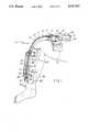
- FIG. 1is a perspective view of a first preferred embodiment of the invention, shown attached to a knee joint.
- FIG. 2is a perspective view of a second preferred embodiment of the invention, shown attached to an elbow and wrist.
- FIG. 3is a perspective view of a third preferred embodiment of the invention, shown attached to an ankle.
- FIGS. 4-6show an embodiment of the invention suitable for the ankle joint.
- FIG. 1shows the preferred embodiment of a dynamic splint 10 used for flexing and extending a joint such as a knee joint or other suitable joints.
- An extendable cable 12has a proximal end 13 and a distal end 14.
- the extendable cable 12includes a fixed cable sleeve 16 the proximal end of which 17 is attached to a cable sleeve mounting bracket 18.
- the cable sleeve mounting bracket 18is releasably attached to an upper limb cuff 19 which mounts to the patient's upper limb 20 using velcro, straps, adhesive tape or other suitable releasable attachment means (not shown).
- the extendable cableincludes an inner cable 22.
- the inner cable 22is rotatably but not slidably mounted in the cable sleeve 16 using suitable O-ring or other retainer means (not shown).
- the proximal end 24 of the inner cable 22extends past the proximal end 17 of the cable sleeve 14 to allow the inner cable 22 to be turned by motor means 28.
- the inner cable 22includes threads 34 on the distal end 36.
- the inner cable threads 34are into mating threads 37 in an inner cable mounting bracket 38 which is attached to a lower limb cuff 40.
- the lower limb cuffis releasably attached to the patient's lower limb 42.
- the cable sleeve 16is not attached to the inner cable mounting bracket 38.
- the dynamic splintoperates by turning the inner cable 22 from its proximate end 24. As the inner cable 22 is turned in one direction, the distal end 36 threads 34 are threaded through the inner cable mounting bracket 38. This effectively reduces the cable length between the inner cable mounting bracket 38 and the cable sleeve mounting bracket 18. The reduction in cable length requires an extension of the joint, since the upper limb 20 and lower limb 42 form an arc smaller than and concentric to the arc of the extendable cable 12. When the inner cable 22 is turned in the opposite direction, the distal end 36 threads 34 are unthreaded through the inner cable mounting bracket 38, to produce an effective lengthening of the extendable cable 12 and a flexing of the joint.
- the cable sleeve 16is substantially rigid to prevent any bowing of the cable as it is extended, except that a relatively short section 43 of the cable adjacent the joint is bendable to accommodate bending of the joint.
- This bendable sectionmust not be too long, or it will tend to bow and will defeat the lengthening of the cable.
- the actual length of the bendable sectionwill depend on the distance between the extendable cable and the limb.
- the bendable sectionmay be rubber tubing, a combination of several rigid shafts with universal joint ends, or any other flexible element.
- the turning of the inner cable 22may be accomplished utilizing motor means 28 or any other source of torque energy.
- the motor meansmay be a stepper motor to allow precise control over the degree of flexing and extending of the joint as well as the amount of force to be applied to achieve that flexing and extending.
- Programmable control means 70may be preset with those parameters.
- the control means 70may also include calibration means to calibrate the system to the particular patient by measuring and storing the number of inner cable revolutions necessary to move the joint through the desired range of motion, to count the number of motion cycles, and to control the motion speed.
- the dynamic splint of FIG. 1may also include additional cuffs to facilitate attachment of the device onto the upper or lower limb, such as the second cuff 46 shown on the lower limb 42.
- the second cuff 46includes a second cuff mounting bracket 48 that slidably engages the cable sleeve 16.
- the second cuff mounting bracket 48is attached to the first cuff mounting bracket 38 with a pair of struts 47 and 49, each with a plurality of mounting holes 51 to receive a screw or shaft 53.
- the distance between the second cuff 46 and the first cuff 40is adjustable by choosing from the plurality of mounting holes 51.
- the apparatusmay also include a hinge (not shown) to control the degree of flexing and extending of the joint.
- An upper hinge armis pivotally mounted to the upper limb cuff 19, and a lower hinge arm is pivotally mounted to the first lower limb cuff 40.
- the two hinge armsare pivotally mounted to each other at their other ends using a rivet.
- the pivotal mount between the two hinge armsis also slidable through a slot in one arm that slides in relation to the rivet in the other arm. This pivotal slidable mount allows for normal joint extension and contraction during flexing and extending of the joint.
- the hingein addition to establishing some control over the path of joint movement, may contain a safety device to limit the amount of flexing and extending of the joint.
- the safety devicemay be a micro-switch which deactivates the stepper motor or other source of torque energy when the arms reach predetermined degrees of flexing or extending.
- FIGS. 2, and 3Another embodiment of the invention is shown in FIGS. 2, and 3 which uses the extendable cable system of the embodiment of FIG. 1 but also provides for supination and pronation as in an elbow and wrist.
- the assemblyincludes a housing 91.
- the housingis hinged in the vicinity of the elbow with hinge means 93.
- the upper housing portion 95is releasably attached to the patient's upper limb 84 and the lower housing portion 79 is releasably attached to the patient's lower limb 98.
- the embodimentuses an extendable cable 70 with a proximal end 72 and distal end 74.
- the extendable cable 70 proximal end 72is mounted to an extendable cable upper mounting bracket 80 which is mounted to the upper housing portion 95.
- the extendable cable 70 proximal end 72extends beyond the upper mounting bracket 80 in order to engage motor means 88.
- the distal end 74 of the extendable cable 70has threads 92.
- the threads 92are threaded through one or more extendable cable lower mounting brackets 94 which are attached to the lower housing portion 79.
- the rotation of the inner threaded cable 84 with the motor means 88causes the extendable cable distal end 74 to thread through the extendable cable lower mounting bracket 94. This effectively extends or reduces the cable length, thereby bending the housing 91 at the hinge 93 and extending or flexing the joint depending on the direction of rotation.
- the portion of the housing that contacts the patient's upper limb 84is equipped with rollers 99 which allow sliding of the upper limb 84 relative to the housing 91. This sliding accommodates normal joint component motion as the joint flexes and extends.
- the housing 91is releasably attached to the limbs 84 and 98 with velcro, strapping or other suitable attachment means (not shown).
- the extendable cable distal end 74has a set of radial holes 96 which receive one or more pins 97 which protrude from the holes.
- the pinsact as a stop against the lower mounting brackets 94 to prevent the assembly from flexing or extending the joint too far. By adjusting the pin to different holes, the degree of flexing and extending can be controlled.
- the lower mounting brackets 94may also include a microswitch or other switching means (not shown) which are activated upon contact with the pins in order to reverse the direction of flexing or extending.
- the apparatus of FIG. 3also includes a means for turning the lower limb 98 to cause supination and pronation of the wrist.
- the pulley cable 100extends through a slot 101 in the lower housing portion 79 and is looped around the lower limb 98 so that rotation of the extendable cable 70 causes a rotation of the pulley 99 and a movement of the pulley cable 100 to rotate the lower limb 98.
- the pulley cable 100is elastic so that it will extend and contract to accommodate different sized limbs.
- the portion of the wrist which is held by the cable pulleymay be covered with a sleeve (not shown) to prevent chafing of the skin against the pulley or against the housing.
- the supination and pronation of the wristmay also be accomplished with a bracelet (not shown) 96 releasably attached to the patient's lower limb with circumferential teeth which mate with longitudinal teeth on the inner cable distal end.
- a biased bracket attached to the lower housing portionapplies a biasing force to urge the inner cable mounting bracket toward the bracelet and to engage the longitudinal teeth with the bracelet circumferential teeth.
- a slot in the lower housing portion 79receives the bracelet.
- the motor means 88may include programmable control means 104 to control the degree of joint flexing and extending, the degree of pronation and supination, and the force limits.
- FIGS. 4, 5 and 6Another embodiment of the invention is shown in FIGS. 4, 5 and 6 which may be used with an ankle joint.
- An upper limb housing 106is releasably attached to patient's upper limb 108.
- the upper limb housing 106has a lower portion 110 which forms a shell around the lower limb 112 which is an ankle heel in the example shown in FIG. 5.
- a heel cup 114Inside the lower portion shell 110 is located a heel cup 114 which is releasably attached to the patient's heel 116.
- the heel cup 114is pivotally attached to the lower portion shell 110 with two independent flexible shafts 118 which extend from the interior of the lower portion shell 110 to the exterior of the heel cup 114.
- One of those shaftsis shown in FIGS.
- the flexible shaftsmay be ordinary helical shafts which bend in any direction but do not twist. In this manner, the heel cup 114 may pivot with respect to the upper limb housing about the flexible shafts 118.
- the flexibility of the shaftsallow some degree of flexibility in the pivot axis to account for joint motion peculiar to each individual's anatomy.
- the outer ends 122 of the flexible shafts 118have enlarged heads which extend through the lower portion shell 110 and are retained thereby.
- the apertures in the lower portion shell 110 through which the flexible shafts 118 and 120 extendare slots 126 which allow the shafts to move as they pivot. This accommodates the normal biomechanical joint motion of the ankle talocrural and subtalar joints.
- the heel cup 114is positively activated to cause pivoting with respect to the upper limb housing 106 about the flexible shafts 118, with the use of a cam 130 and motor means 132.
- the camis pivotally mounted on the bottom interior surface of the lower portion shell 110 on a cam pivot 134.
- the cam pivot 134is activated by the motor means 132. Activation of the cam 130 applies a force to the bottom of the heel cup 114 tangential to the pivot axis of the flexible shafts 118 and 120, thereby causing a pivoting of the heel cup 114 with respect to the upper limb housing 106.
- the motor meansmay include programmable control means to control the degree of pivoting and amount of force applied.
- the apparatus of FIGS. 4, 5 and 6may be adapted to apply a continuous static force to the ankle joint by use of a spring or other biasing means (not shown) between the back of the heel cup 114 and the inside of the lower portion 110 of the upper limb housing 106.
- a spring or other biasing means(not shown) between the back of the heel cup 114 and the inside of the lower portion 110 of the upper limb housing 106.
Landscapes
- Health & Medical Sciences (AREA)
- Life Sciences & Earth Sciences (AREA)
- Veterinary Medicine (AREA)
- Public Health (AREA)
- General Health & Medical Sciences (AREA)
- Animal Behavior & Ethology (AREA)
- Biomedical Technology (AREA)
- Vascular Medicine (AREA)
- Heart & Thoracic Surgery (AREA)
- Engineering & Computer Science (AREA)
- Orthopedic Medicine & Surgery (AREA)
- Nursing (AREA)
- Epidemiology (AREA)
- Pain & Pain Management (AREA)
- Physical Education & Sports Medicine (AREA)
- Rehabilitation Therapy (AREA)
- Orthopedics, Nursing, And Contraception (AREA)
Abstract
Description
Claims (10)
Priority Applications (6)
| Application Number | Priority Date | Filing Date | Title |
|---|---|---|---|
| US07/495,044US5117814A (en) | 1990-03-16 | 1990-03-16 | Dynamic splint |
| US07/507,212US5178137A (en) | 1990-03-16 | 1990-04-09 | Segmented dynamic splint |
| US07/550,256US5144943A (en) | 1990-03-16 | 1990-07-09 | Dynamic ankle splint |
| PCT/US1991/001792WO1991013604A1 (en) | 1990-03-16 | 1991-03-18 | Dynamic splint |
| US07/841,625US5352190A (en) | 1990-03-16 | 1992-02-26 | Knee brace |
| US08/226,169US5547464A (en) | 1990-03-16 | 1994-04-12 | Joint device |
Applications Claiming Priority (1)
| Application Number | Priority Date | Filing Date | Title |
|---|---|---|---|
| US07/495,044US5117814A (en) | 1990-03-16 | 1990-03-16 | Dynamic splint |
Related Child Applications (3)
| Application Number | Title | Priority Date | Filing Date |
|---|---|---|---|
| US07/507,212Continuation-In-PartUS5178137A (en) | 1990-03-16 | 1990-04-09 | Segmented dynamic splint |
| US07/550,256Continuation-In-PartUS5144943A (en) | 1990-03-16 | 1990-07-09 | Dynamic ankle splint |
| US07/841,625Continuation-In-PartUS5352190A (en) | 1990-03-16 | 1992-02-26 | Knee brace |
Publications (1)
| Publication Number | Publication Date |
|---|---|
| US5117814Atrue US5117814A (en) | 1992-06-02 |
Family
ID=23967027
Family Applications (1)
| Application Number | Title | Priority Date | Filing Date |
|---|---|---|---|
| US07/495,044Expired - LifetimeUS5117814A (en) | 1990-03-16 | 1990-03-16 | Dynamic splint |
Country Status (1)
| Country | Link |
|---|---|
| US (1) | US5117814A (en) |
Cited By (79)
| Publication number | Priority date | Publication date | Assignee | Title |
|---|---|---|---|---|
| USD331712S (en) | 1991-02-21 | 1992-12-15 | Scribner David W | Dynamometer |
| US5219323A (en)* | 1991-06-21 | 1993-06-15 | Electrobionics Corporation | Method and apparatus for rotating a wrist |
| US5312322A (en)* | 1992-11-02 | 1994-05-17 | The United States Of America As Represented By The Secretary Of The Navy | Three point extension splint to treat flexion contractures about limb synovial hinge joints |
| US5330417A (en)* | 1989-05-11 | 1994-07-19 | Ken Petersen | Method and an apparatus for joint-controlled training of different motoric units for development of functional muscle strength and proprioceptivity |
| US5337737A (en)* | 1992-01-13 | 1994-08-16 | Albert Einstein College Of Medicine Of Yeshiva University | Dynamic orthosis with proportional resistance |
| US5372597A (en)* | 1993-05-12 | 1994-12-13 | Smith & Nephew Richards, Inc. | Supination-pronation device |
| US5484394A (en)* | 1991-06-21 | 1996-01-16 | Electrobionics Corporation | Method and apparatus for rotating a wrist |
| US5575764A (en)* | 1994-12-14 | 1996-11-19 | Van Dyne; Leonard A. | Prosthetic joint with dynamic torque compensator |
| US5658241A (en)* | 1990-02-09 | 1997-08-19 | Ultraflex Systems, Inc. | Multi-functional dynamic splint |
| US5662594A (en)* | 1995-06-09 | 1997-09-02 | Rosenblatt; Marc | Dynamic exoskeletal orthosis |
| US5716330A (en)* | 1995-07-13 | 1998-02-10 | Goldman; David A. | Body and limb position/motion detector and power assist apparatus and method |
| US5857989A (en)* | 1997-11-24 | 1999-01-12 | Smith, Iii; Kirby | Dynamic orthopedic knee brace assembly |
| US5865770A (en)* | 1995-12-06 | 1999-02-02 | Schectman; Leonard A. | Device to counteract paralysis |
| US5891061A (en)* | 1997-02-20 | 1999-04-06 | Jace Systems, Inc. | Brace for applying a dynamic force to a jointed limb |
| US5954621A (en)* | 1993-07-09 | 1999-09-21 | Kinetecs, Inc. | Exercise apparatus and technique |
| US5980435A (en)* | 1993-07-09 | 1999-11-09 | Kinetecs, Inc. | Methods of therapy or controlled exercise using a jointed brace |
| US6179799B1 (en) | 1999-02-01 | 2001-01-30 | Robert E. Doran | Orthosis for supination and pronation of the wrist |
| EP1112731A3 (en)* | 1999-12-27 | 2002-07-31 | Medireha Gmbh | Therapy apparatus |
| WO2001068028A3 (en)* | 2000-03-14 | 2002-12-27 | Orthologic Corp | Combination pro/supination and flexion therapeutic mobilization device |
| WO2003003953A1 (en)* | 2001-07-06 | 2003-01-16 | University Of Reading | Rotatable joint stop mechanism |
| US6537237B1 (en) | 2001-09-28 | 2003-03-25 | R & R Holdings, Llc | Orthotic device |
| WO2000009066A3 (en)* | 1998-08-10 | 2003-07-03 | Thomas P M D Branch | Orthotic apparatus and method for using same |
| US20030125651A1 (en)* | 2001-12-31 | 2003-07-03 | R & R Holdings, Llc | Supination/pronation therapy device |
| US20030130600A1 (en)* | 2001-12-13 | 2003-07-10 | Branch Thomas P. | Shoulder extension control device |
| US20030144620A1 (en)* | 2001-09-28 | 2003-07-31 | Sieller Richard T. | Orthotic device |
| EP1374810A1 (en)* | 2002-06-28 | 2004-01-02 | Tamarack Habilitation Technologies, Inc. | Adjustable mounting housing for prosthetic ankle flexure joint |
| EP1410774A1 (en)* | 2002-10-18 | 2004-04-21 | Tob NV | Orthotic device with detachable motor unit |
| US20040106886A1 (en)* | 2002-09-12 | 2004-06-03 | Rene Verdonk | Orthopedic arm and shoulder brace |
| US20050245853A1 (en)* | 2002-04-16 | 2005-11-03 | Scorvo Sean K | Adjustable orthotic brace |
| US20050251076A1 (en)* | 2004-04-09 | 2005-11-10 | Branch Thomas P | Method and apparatus for multidirectional positioning of a shoulder |
| US7066896B1 (en) | 2002-11-12 | 2006-06-27 | Kiselik Daniel R | Interactive apparatus and method for developing ability in the neuromuscular system |
| ES2260986A1 (en)* | 2003-12-11 | 2006-11-01 | Asociacion Instituto De Biomecanica De Valencia | Orthesis for controlling pronosupination movement, allows control of rotary movement relative to wrist with respect to forearm axis |
| US20070173747A1 (en)* | 2006-01-24 | 2007-07-26 | Knotts Jesse A | Joint stimulator |
| US20070219475A1 (en)* | 2006-03-17 | 2007-09-20 | Bonutti Boris P | Ankle orthosis |
| US20070270976A1 (en)* | 2002-04-25 | 2007-11-22 | Ultraflex Systems, Inc. | Ambulating ankle & knee joints with bidirectional dampening and assistance using elastomeric restraint |
| US20080195005A1 (en)* | 2007-02-14 | 2008-08-14 | Horst Robert W | Methods and devices for deep vein thrombosis prevention |
| US20090036804A1 (en)* | 2002-11-25 | 2009-02-05 | Horst Robert W | Power regeneration in active muscle assistance device and method |
| US7507215B2 (en) | 2005-07-08 | 2009-03-24 | Jri Development Group, Llc | Orthotic brace |
| US20090198162A1 (en)* | 2002-04-25 | 2009-08-06 | Ultraflex Sytems, Inc. | Ambulating knee joint |
| US20090204038A1 (en)* | 2008-02-08 | 2009-08-13 | Tibion Corporation | Multi-fit orthotic and mobility assistance apparatus |
| US20090210093A1 (en)* | 2006-07-17 | 2009-08-20 | Jacobsen Stephen C | Contact displacement actuator system |
| US20090306548A1 (en)* | 2008-06-05 | 2009-12-10 | Bhugra Kern S | Therapeutic method and device for rehabilitation |
| US20100038983A1 (en)* | 2008-08-14 | 2010-02-18 | Kern Bhugra | Actuator system with a motor assembly and latch for extending and flexing a joint |
| US20100039052A1 (en)* | 2008-08-14 | 2010-02-18 | Horst Robert W | Actuator system with a multi-motor assembly for extending and flexing a joint |
| US20100198124A1 (en)* | 2009-01-30 | 2010-08-05 | Kern Bhugra | System and method for controlling the joint motion of a user based on a measured physiological property |
| US20100204620A1 (en)* | 2009-02-09 | 2010-08-12 | Smith Jonathan A | Therapy and mobility assistance system |
| US20100211355A1 (en)* | 2009-02-09 | 2010-08-19 | Horst Robert W | Foot pad device and method of obtaining weight data |
| US20110313331A1 (en)* | 2009-02-10 | 2011-12-22 | Bruno Marc Florent Victore Dehez | Rehabilitation Robot |
| US8870802B1 (en) | 2011-04-13 | 2014-10-28 | Water Crest Industries LLC | Traction splint |
| JP2016054803A (en)* | 2014-09-05 | 2016-04-21 | 学校法人早稲田大学 | Frame interlocking mechanism for brace |
| US20160229049A1 (en)* | 2014-05-02 | 2016-08-11 | Ekso Bionics, Inc. | Exoskeleton and Method of Increasing the Flexibility of an Exoskeleton Joint |
| US9889058B2 (en) | 2013-03-15 | 2018-02-13 | Alterg, Inc. | Orthotic device drive system and method |
| CN109009605A (en)* | 2018-08-31 | 2018-12-18 | 中国人民解放军第四军医大学 | Knee joint apparatus for correcting |
| CN109079752A (en)* | 2018-07-27 | 2018-12-25 | 北京机械设备研究所 | A kind of man-machine attachment device of ectoskeleton thigh based on linear bearing |
| US10765537B2 (en) | 2016-11-11 | 2020-09-08 | Sarcos Corp. | Tunable actuator joint modules having energy recovering quasi-passive elastic actuators for use within a robotic system |
| US10766133B2 (en) | 2014-05-06 | 2020-09-08 | Sarcos Lc | Legged robotic device utilizing modifiable linkage mechanism |
| US10780588B2 (en) | 2012-05-14 | 2020-09-22 | Sarcos Lc | End effector for a robotic arm |
| US10821614B2 (en) | 2016-11-11 | 2020-11-03 | Sarcos Corp. | Clutched joint modules having a quasi-passive elastic actuator for a robotic assembly |
| US10828767B2 (en) | 2016-11-11 | 2020-11-10 | Sarcos Corp. | Tunable actuator joint modules having energy recovering quasi-passive elastic actuators with internal valve arrangements |
| US10843330B2 (en) | 2017-12-07 | 2020-11-24 | Sarcos Corp. | Resistance-based joint constraint for a master robotic system |
| US10906191B2 (en) | 2018-12-31 | 2021-02-02 | Sarcos Corp. | Hybrid robotic end effector |
| US10919161B2 (en) | 2016-11-11 | 2021-02-16 | Sarcos Corp. | Clutched joint modules for a robotic system |
| CN113171267A (en)* | 2021-04-21 | 2021-07-27 | 吉林大学第一医院 | A kind of knee joint ligament rupture rehabilitation training device for preventing flexion and extension injury |
| US11123608B2 (en)* | 2019-03-05 | 2021-09-21 | Hiwin Technologies Corp. | Upper limb training system and control method thereof |
| US11241801B2 (en) | 2018-12-31 | 2022-02-08 | Sarcos Corp. | Robotic end effector with dorsally supported actuation mechanism |
| US20220133576A1 (en)* | 2019-11-15 | 2022-05-05 | H Robotics Inc. | Rehabilitation exercise device for upper and lower limbs |
| US11331809B2 (en) | 2017-12-18 | 2022-05-17 | Sarcos Corp. | Dynamically controlled robotic stiffening element |
| US11351675B2 (en) | 2018-12-31 | 2022-06-07 | Sarcos Corp. | Robotic end-effector having dynamic stiffening elements for conforming object interaction |
| SE2130023A1 (en)* | 2021-01-27 | 2022-07-28 | Embreis Ab | Ortho joint |
| WO2023034244A3 (en)* | 2021-09-03 | 2023-04-27 | Kenai Design, Llc | Dynamic splint |
| US11717956B1 (en) | 2022-08-29 | 2023-08-08 | Sarcos Corp. | Robotic joint system with integrated safety |
| US11738446B2 (en) | 2011-04-29 | 2023-08-29 | Sarcos, Lc | Teleoperated robotic system with impact responsive force feedback |
| US11794345B2 (en) | 2020-12-31 | 2023-10-24 | Sarcos Corp. | Unified robotic vehicle systems and methods of control |
| US11826907B1 (en) | 2022-08-17 | 2023-11-28 | Sarcos Corp. | Robotic joint system with length adapter |
| US11833676B2 (en) | 2020-12-07 | 2023-12-05 | Sarcos Corp. | Combining sensor output data to prevent unsafe operation of an exoskeleton |
| US11897132B1 (en) | 2022-11-17 | 2024-02-13 | Sarcos Corp. | Systems and methods for redundant network communication in a robot |
| US11924023B1 (en) | 2022-11-17 | 2024-03-05 | Sarcos Corp. | Systems and methods for redundant network communication in a robot |
| US20240415717A1 (en)* | 2014-02-25 | 2024-12-19 | Jumpsport, Inc. | Knee and joint rehabilitation exercise device |
| US12172298B2 (en) | 2022-11-04 | 2024-12-24 | Sarcos Corp. | Robotic end-effector having dynamic stiffening elements with resilient spacers for conforming object interaction |
Citations (9)
| Publication number | Priority date | Publication date | Assignee | Title |
|---|---|---|---|---|
| US3323518A (en)* | 1964-04-10 | 1967-06-06 | Howard M Swanson | Device for inducing motion to a joint |
| US4407496A (en)* | 1981-12-14 | 1983-10-04 | Johnson David E | Limb exercise device |
| US4644938A (en)* | 1985-01-22 | 1987-02-24 | Danninger Medical Technology | Hand exerciser |
| US4665900A (en)* | 1981-10-23 | 1987-05-19 | Toronto Medical Corp. | Device for imparting continuous passive motion to human joints |
| US4669451A (en)* | 1983-12-15 | 1987-06-02 | Ernst Knoll | Apparatus for postoperative and other exercising of elbow and shoulder joints |
| US4772012A (en)* | 1986-10-03 | 1988-09-20 | The Christine M. Kleinert Institute For Hand And Micro-Surgery, Inc. | Postoperative dynamic hand splint |
| US4801138A (en)* | 1987-12-01 | 1989-01-31 | Soma Dynamics Corporation | Wearable apparatus for exercising body joints |
| US4862875A (en)* | 1987-03-31 | 1989-09-05 | Samuel Heaton | Leg exercisers |
| US4875469A (en)* | 1988-06-13 | 1989-10-24 | Innovative Medical Engineering, Inc. | Continuous passive motion devices and methods |
- 1990
- 1990-03-16USUS07/495,044patent/US5117814A/ennot_activeExpired - Lifetime
Patent Citations (9)
| Publication number | Priority date | Publication date | Assignee | Title |
|---|---|---|---|---|
| US3323518A (en)* | 1964-04-10 | 1967-06-06 | Howard M Swanson | Device for inducing motion to a joint |
| US4665900A (en)* | 1981-10-23 | 1987-05-19 | Toronto Medical Corp. | Device for imparting continuous passive motion to human joints |
| US4407496A (en)* | 1981-12-14 | 1983-10-04 | Johnson David E | Limb exercise device |
| US4669451A (en)* | 1983-12-15 | 1987-06-02 | Ernst Knoll | Apparatus for postoperative and other exercising of elbow and shoulder joints |
| US4644938A (en)* | 1985-01-22 | 1987-02-24 | Danninger Medical Technology | Hand exerciser |
| US4772012A (en)* | 1986-10-03 | 1988-09-20 | The Christine M. Kleinert Institute For Hand And Micro-Surgery, Inc. | Postoperative dynamic hand splint |
| US4862875A (en)* | 1987-03-31 | 1989-09-05 | Samuel Heaton | Leg exercisers |
| US4801138A (en)* | 1987-12-01 | 1989-01-31 | Soma Dynamics Corporation | Wearable apparatus for exercising body joints |
| US4875469A (en)* | 1988-06-13 | 1989-10-24 | Innovative Medical Engineering, Inc. | Continuous passive motion devices and methods |
Cited By (126)
| Publication number | Priority date | Publication date | Assignee | Title |
|---|---|---|---|---|
| US5330417A (en)* | 1989-05-11 | 1994-07-19 | Ken Petersen | Method and an apparatus for joint-controlled training of different motoric units for development of functional muscle strength and proprioceptivity |
| US5658241A (en)* | 1990-02-09 | 1997-08-19 | Ultraflex Systems, Inc. | Multi-functional dynamic splint |
| USD331712S (en) | 1991-02-21 | 1992-12-15 | Scribner David W | Dynamometer |
| US5219323A (en)* | 1991-06-21 | 1993-06-15 | Electrobionics Corporation | Method and apparatus for rotating a wrist |
| US5484394A (en)* | 1991-06-21 | 1996-01-16 | Electrobionics Corporation | Method and apparatus for rotating a wrist |
| US5337737A (en)* | 1992-01-13 | 1994-08-16 | Albert Einstein College Of Medicine Of Yeshiva University | Dynamic orthosis with proportional resistance |
| US5312322A (en)* | 1992-11-02 | 1994-05-17 | The United States Of America As Represented By The Secretary Of The Navy | Three point extension splint to treat flexion contractures about limb synovial hinge joints |
| US5372597A (en)* | 1993-05-12 | 1994-12-13 | Smith & Nephew Richards, Inc. | Supination-pronation device |
| US5980435A (en)* | 1993-07-09 | 1999-11-09 | Kinetecs, Inc. | Methods of therapy or controlled exercise using a jointed brace |
| US5954621A (en)* | 1993-07-09 | 1999-09-21 | Kinetecs, Inc. | Exercise apparatus and technique |
| US5624390A (en)* | 1994-12-14 | 1997-04-29 | Van Dyne; Leonard A. | Prosthetic joint with dynamic torque compensator |
| US5575764A (en)* | 1994-12-14 | 1996-11-19 | Van Dyne; Leonard A. | Prosthetic joint with dynamic torque compensator |
| US5662594A (en)* | 1995-06-09 | 1997-09-02 | Rosenblatt; Marc | Dynamic exoskeletal orthosis |
| US5716330A (en)* | 1995-07-13 | 1998-02-10 | Goldman; David A. | Body and limb position/motion detector and power assist apparatus and method |
| US5865770A (en)* | 1995-12-06 | 1999-02-02 | Schectman; Leonard A. | Device to counteract paralysis |
| US5891061A (en)* | 1997-02-20 | 1999-04-06 | Jace Systems, Inc. | Brace for applying a dynamic force to a jointed limb |
| USRE37297E1 (en)* | 1997-11-24 | 2001-07-24 | Smith, Iii Kirby | Dynamic orthopedic knee brace assembly |
| US5857989A (en)* | 1997-11-24 | 1999-01-12 | Smith, Iii; Kirby | Dynamic orthopedic knee brace assembly |
| US20110218469A1 (en)* | 1998-08-10 | 2011-09-08 | Branch Thomas P | Orthotic apparatus and method for using same |
| US7479121B2 (en) | 1998-08-10 | 2009-01-20 | Branch Thomas P | Orthotic apparatus and method for using same |
| WO2000009066A3 (en)* | 1998-08-10 | 2003-07-03 | Thomas P M D Branch | Orthotic apparatus and method for using same |
| US20040171973A1 (en)* | 1998-08-10 | 2004-09-02 | Branch Thomas P. | Orthotic apparatus and method for using same |
| US6669660B2 (en) | 1998-08-10 | 2003-12-30 | Thomas P. Branch | Orthotic apparatus and method for using same |
| US20090143708A1 (en)* | 1998-08-10 | 2009-06-04 | Branch Thomas P | Orthotic apparatus and method for using same |
| US8361002B2 (en) | 1998-08-10 | 2013-01-29 | Ermi, Inc. | Orthotic apparatus and method for using same |
| US6179799B1 (en) | 1999-02-01 | 2001-01-30 | Robert E. Doran | Orthosis for supination and pronation of the wrist |
| EP1112731A3 (en)* | 1999-12-27 | 2002-07-31 | Medireha Gmbh | Therapy apparatus |
| WO2001068028A3 (en)* | 2000-03-14 | 2002-12-27 | Orthologic Corp | Combination pro/supination and flexion therapeutic mobilization device |
| US7101347B2 (en) | 2000-03-14 | 2006-09-05 | Orthorehab., Inc. | Combination pro/supination and flexion therapeutic mobilization device |
| WO2003003953A1 (en)* | 2001-07-06 | 2003-01-16 | University Of Reading | Rotatable joint stop mechanism |
| US7048704B2 (en) | 2001-09-28 | 2006-05-23 | Sieller Richard T | Orthotic device |
| US20030144620A1 (en)* | 2001-09-28 | 2003-07-31 | Sieller Richard T. | Orthotic device |
| US6537237B1 (en) | 2001-09-28 | 2003-03-25 | R & R Holdings, Llc | Orthotic device |
| US7547289B2 (en) | 2001-12-13 | 2009-06-16 | Ermi Corporation | Shoulder extension control device |
| US20030130600A1 (en)* | 2001-12-13 | 2003-07-10 | Branch Thomas P. | Shoulder extension control device |
| US6866646B2 (en) | 2001-12-31 | 2005-03-15 | R & R Holdings, Llc | Supination/pronation therapy device |
| US20030125651A1 (en)* | 2001-12-31 | 2003-07-03 | R & R Holdings, Llc | Supination/pronation therapy device |
| US20050245853A1 (en)* | 2002-04-16 | 2005-11-03 | Scorvo Sean K | Adjustable orthotic brace |
| US8123709B2 (en) | 2002-04-25 | 2012-02-28 | Ultraflex Systems, Inc. | Ambulating knee joint |
| US8100844B2 (en) | 2002-04-25 | 2012-01-24 | Ultraflex Systems, Inc. | Ambulating ankle and knee joints with bidirectional dampening and assistance using elastomeric restraint |
| US20070270976A1 (en)* | 2002-04-25 | 2007-11-22 | Ultraflex Systems, Inc. | Ambulating ankle & knee joints with bidirectional dampening and assistance using elastomeric restraint |
| US20090198162A1 (en)* | 2002-04-25 | 2009-08-06 | Ultraflex Sytems, Inc. | Ambulating knee joint |
| EP1374810A1 (en)* | 2002-06-28 | 2004-01-02 | Tamarack Habilitation Technologies, Inc. | Adjustable mounting housing for prosthetic ankle flexure joint |
| US6824523B2 (en) | 2002-06-28 | 2004-11-30 | Tamarack Habilitation Technologies, Inc. | Adjustable mounting housing for orthotic ankle flexure joint |
| US20040106886A1 (en)* | 2002-09-12 | 2004-06-03 | Rene Verdonk | Orthopedic arm and shoulder brace |
| US7354412B2 (en)* | 2002-09-12 | 2008-04-08 | Universiteit Gent | Orthopedic arm and shoulder brace |
| EP1410774A1 (en)* | 2002-10-18 | 2004-04-21 | Tob NV | Orthotic device with detachable motor unit |
| US7066896B1 (en) | 2002-11-12 | 2006-06-27 | Kiselik Daniel R | Interactive apparatus and method for developing ability in the neuromuscular system |
| US20100318006A1 (en)* | 2002-11-25 | 2010-12-16 | Horst Robert W | Power regeneration in active muscle assistance device and method |
| US20090036804A1 (en)* | 2002-11-25 | 2009-02-05 | Horst Robert W | Power regeneration in active muscle assistance device and method |
| US8679040B2 (en) | 2002-11-25 | 2014-03-25 | Alterg, Inc. | Intention-based therapy device and method |
| ES2260986B1 (en)* | 2003-12-11 | 2007-12-01 | Asociacion Instituto De Biomecanica De Valencia | ORTHESIS FOR THE CONTROL OF THE PRONOSUPINATION MOVEMENT. |
| ES2260986A1 (en)* | 2003-12-11 | 2006-11-01 | Asociacion Instituto De Biomecanica De Valencia | Orthesis for controlling pronosupination movement, allows control of rotary movement relative to wrist with respect to forearm axis |
| US20050251076A1 (en)* | 2004-04-09 | 2005-11-10 | Branch Thomas P | Method and apparatus for multidirectional positioning of a shoulder |
| US7686775B2 (en) | 2004-04-09 | 2010-03-30 | Branch Thomas P | Method and apparatus for multidirectional positioning of a shoulder |
| US7507215B2 (en) | 2005-07-08 | 2009-03-24 | Jri Development Group, Llc | Orthotic brace |
| US20070173747A1 (en)* | 2006-01-24 | 2007-07-26 | Knotts Jesse A | Joint stimulator |
| US8251935B2 (en)* | 2006-03-17 | 2012-08-28 | Bonutti Research, Inc. | Ankle orthosis |
| US11266520B2 (en) | 2006-03-17 | 2022-03-08 | Bonutti Research, Inc. | Ankle orthosis |
| US10159590B2 (en) | 2006-03-17 | 2018-12-25 | Bonutti Research, Inc. | Toe orthosis |
| US20070219475A1 (en)* | 2006-03-17 | 2007-09-20 | Bonutti Boris P | Ankle orthosis |
| US8849457B2 (en)* | 2006-07-17 | 2014-09-30 | Raytheon Company | Contact displacement actuator system |
| US20090210093A1 (en)* | 2006-07-17 | 2009-08-20 | Jacobsen Stephen C | Contact displacement actuator system |
| US8353854B2 (en) | 2007-02-14 | 2013-01-15 | Tibion Corporation | Method and devices for moving a body joint |
| US9474673B2 (en) | 2007-02-14 | 2016-10-25 | Alterg, Inc. | Methods and devices for deep vein thrombosis prevention |
| US20080195005A1 (en)* | 2007-02-14 | 2008-08-14 | Horst Robert W | Methods and devices for deep vein thrombosis prevention |
| US8771211B2 (en)* | 2007-03-16 | 2014-07-08 | Bonutti Research, Inc. | Ankle orthosis |
| US20120310121A1 (en)* | 2007-03-16 | 2012-12-06 | Bonutti Boris P | Ankle orthosis |
| US8771210B2 (en) | 2008-02-08 | 2014-07-08 | Alterg, Inc. | Multi-fit orthotic and mobility assistance apparatus |
| US8052629B2 (en) | 2008-02-08 | 2011-11-08 | Tibion Corporation | Multi-fit orthotic and mobility assistance apparatus |
| US20090204038A1 (en)* | 2008-02-08 | 2009-08-13 | Tibion Corporation | Multi-fit orthotic and mobility assistance apparatus |
| US10179078B2 (en) | 2008-06-05 | 2019-01-15 | Alterg, Inc. | Therapeutic method and device for rehabilitation |
| US20090306548A1 (en)* | 2008-06-05 | 2009-12-10 | Bhugra Kern S | Therapeutic method and device for rehabilitation |
| US20100039052A1 (en)* | 2008-08-14 | 2010-02-18 | Horst Robert W | Actuator system with a multi-motor assembly for extending and flexing a joint |
| US8058823B2 (en)* | 2008-08-14 | 2011-11-15 | Tibion Corporation | Actuator system with a multi-motor assembly for extending and flexing a joint |
| US8274244B2 (en) | 2008-08-14 | 2012-09-25 | Tibion Corporation | Actuator system and method for extending a joint |
| US20100038983A1 (en)* | 2008-08-14 | 2010-02-18 | Kern Bhugra | Actuator system with a motor assembly and latch for extending and flexing a joint |
| US20100198124A1 (en)* | 2009-01-30 | 2010-08-05 | Kern Bhugra | System and method for controlling the joint motion of a user based on a measured physiological property |
| US8639455B2 (en) | 2009-02-09 | 2014-01-28 | Alterg, Inc. | Foot pad device and method of obtaining weight data |
| US20100211355A1 (en)* | 2009-02-09 | 2010-08-19 | Horst Robert W | Foot pad device and method of obtaining weight data |
| US20100204620A1 (en)* | 2009-02-09 | 2010-08-12 | Smith Jonathan A | Therapy and mobility assistance system |
| US9131873B2 (en) | 2009-02-09 | 2015-09-15 | Alterg, Inc. | Foot pad device and method of obtaining weight data |
| US20110313331A1 (en)* | 2009-02-10 | 2011-12-22 | Bruno Marc Florent Victore Dehez | Rehabilitation Robot |
| US8870802B1 (en) | 2011-04-13 | 2014-10-28 | Water Crest Industries LLC | Traction splint |
| US11745331B2 (en) | 2011-04-29 | 2023-09-05 | Sarcos, Lc | Teleoperated robotic system with payload stabilization |
| US11865705B2 (en) | 2011-04-29 | 2024-01-09 | Sarcos, Lc | Teleoperated robotic system |
| US11738446B2 (en) | 2011-04-29 | 2023-08-29 | Sarcos, Lc | Teleoperated robotic system with impact responsive force feedback |
| US10780588B2 (en) | 2012-05-14 | 2020-09-22 | Sarcos Lc | End effector for a robotic arm |
| US9889058B2 (en) | 2013-03-15 | 2018-02-13 | Alterg, Inc. | Orthotic device drive system and method |
| US11007105B2 (en) | 2013-03-15 | 2021-05-18 | Alterg, Inc. | Orthotic device drive system and method |
| US20240415717A1 (en)* | 2014-02-25 | 2024-12-19 | Jumpsport, Inc. | Knee and joint rehabilitation exercise device |
| US9782892B2 (en)* | 2014-05-02 | 2017-10-10 | Ekso Bionics, Inc. | Exoskeleton and method of increasing the flexibility of an exoskeleton joint |
| US10583551B2 (en) | 2014-05-02 | 2020-03-10 | Ekso Bionics, Inc. | Exoskeleton and method of increasing the flexibility of an exoskeleton joint |
| US20160229049A1 (en)* | 2014-05-02 | 2016-08-11 | Ekso Bionics, Inc. | Exoskeleton and Method of Increasing the Flexibility of an Exoskeleton Joint |
| US10766133B2 (en) | 2014-05-06 | 2020-09-08 | Sarcos Lc | Legged robotic device utilizing modifiable linkage mechanism |
| JP2016054803A (en)* | 2014-09-05 | 2016-04-21 | 学校法人早稲田大学 | Frame interlocking mechanism for brace |
| US10919161B2 (en) | 2016-11-11 | 2021-02-16 | Sarcos Corp. | Clutched joint modules for a robotic system |
| US10821614B2 (en) | 2016-11-11 | 2020-11-03 | Sarcos Corp. | Clutched joint modules having a quasi-passive elastic actuator for a robotic assembly |
| US11981027B2 (en) | 2016-11-11 | 2024-05-14 | Sarcos Corp. | Tunable actuator joint modules having energy recovering quasi-passive elastic actuators with internal valve arrangements |
| US11926044B2 (en) | 2016-11-11 | 2024-03-12 | Sarcos Corp. | Clutched joint modules having a quasi-passive elastic actuator for a robotic assembly |
| US11772283B2 (en) | 2016-11-11 | 2023-10-03 | Sarcos Corp. | Clutched joint modules having a quasi-passive elastic actuator for a robotic assembly |
| US10828767B2 (en) | 2016-11-11 | 2020-11-10 | Sarcos Corp. | Tunable actuator joint modules having energy recovering quasi-passive elastic actuators with internal valve arrangements |
| US11759944B2 (en) | 2016-11-11 | 2023-09-19 | Sarcos Corp. | Tunable actuator joint modules having energy recovering quasi- passive elastic actuators with internal valve arrangements |
| US10765537B2 (en) | 2016-11-11 | 2020-09-08 | Sarcos Corp. | Tunable actuator joint modules having energy recovering quasi-passive elastic actuators for use within a robotic system |
| US10843330B2 (en) | 2017-12-07 | 2020-11-24 | Sarcos Corp. | Resistance-based joint constraint for a master robotic system |
| US11331809B2 (en) | 2017-12-18 | 2022-05-17 | Sarcos Corp. | Dynamically controlled robotic stiffening element |
| CN109079752A (en)* | 2018-07-27 | 2018-12-25 | 北京机械设备研究所 | A kind of man-machine attachment device of ectoskeleton thigh based on linear bearing |
| CN109009605A (en)* | 2018-08-31 | 2018-12-18 | 中国人民解放军第四军医大学 | Knee joint apparatus for correcting |
| US11679511B2 (en) | 2018-12-31 | 2023-06-20 | Sarcos Corp. | Robotic end effector with dorsally supported actuation mechanism |
| US11351675B2 (en) | 2018-12-31 | 2022-06-07 | Sarcos Corp. | Robotic end-effector having dynamic stiffening elements for conforming object interaction |
| US10906191B2 (en) | 2018-12-31 | 2021-02-02 | Sarcos Corp. | Hybrid robotic end effector |
| US11241801B2 (en) | 2018-12-31 | 2022-02-08 | Sarcos Corp. | Robotic end effector with dorsally supported actuation mechanism |
| US11123608B2 (en)* | 2019-03-05 | 2021-09-21 | Hiwin Technologies Corp. | Upper limb training system and control method thereof |
| US12097158B2 (en)* | 2019-11-15 | 2024-09-24 | H Robotics Inc. | Rehabilitation exercise device for upper and lower limbs |
| US20220133576A1 (en)* | 2019-11-15 | 2022-05-05 | H Robotics Inc. | Rehabilitation exercise device for upper and lower limbs |
| US11833676B2 (en) | 2020-12-07 | 2023-12-05 | Sarcos Corp. | Combining sensor output data to prevent unsafe operation of an exoskeleton |
| US11794345B2 (en) | 2020-12-31 | 2023-10-24 | Sarcos Corp. | Unified robotic vehicle systems and methods of control |
| SE2130023A1 (en)* | 2021-01-27 | 2022-07-28 | Embreis Ab | Ortho joint |
| SE546539C2 (en)* | 2021-01-27 | 2024-11-26 | Bengt Randstroem Consulting Ab | ADJUSTABLE ORTHOSIS INCLUDING TWO OR MORE SPRING ELEMENTS |
| CN113171267A (en)* | 2021-04-21 | 2021-07-27 | 吉林大学第一医院 | A kind of knee joint ligament rupture rehabilitation training device for preventing flexion and extension injury |
| WO2023034244A3 (en)* | 2021-09-03 | 2023-04-27 | Kenai Design, Llc | Dynamic splint |
| US11826907B1 (en) | 2022-08-17 | 2023-11-28 | Sarcos Corp. | Robotic joint system with length adapter |
| US11717956B1 (en) | 2022-08-29 | 2023-08-08 | Sarcos Corp. | Robotic joint system with integrated safety |
| US12172298B2 (en) | 2022-11-04 | 2024-12-24 | Sarcos Corp. | Robotic end-effector having dynamic stiffening elements with resilient spacers for conforming object interaction |
| US11897132B1 (en) | 2022-11-17 | 2024-02-13 | Sarcos Corp. | Systems and methods for redundant network communication in a robot |
| US11924023B1 (en) | 2022-11-17 | 2024-03-05 | Sarcos Corp. | Systems and methods for redundant network communication in a robot |
Similar Documents
| Publication | Publication Date | Title |
|---|---|---|
| US5117814A (en) | Dynamic splint | |
| WO1991013604A1 (en) | Dynamic splint | |
| US5547464A (en) | Joint device | |
| US5178137A (en) | Segmented dynamic splint | |
| US11266520B2 (en) | Ankle orthosis | |
| US5352190A (en) | Knee brace | |
| CA2065669C (en) | Adjustable orthosis | |
| US11123212B2 (en) | Elbow orthosis | |
| US10456314B2 (en) | Range of motion device | |
| US9320669B2 (en) | Range of motion system | |
| US5472410A (en) | Adjustable flexion and extension joint orthoses | |
| US20250143908A1 (en) | Orthosis for range of motion | |
| US9980871B2 (en) | Knee orthosis | |
| US10667938B2 (en) | Orthosis for range of motion | |
| US5954721A (en) | Devices for passive motion of joints under traction | |
| US20240315862A1 (en) | Orthosis for range of motion for amputee | |
| RU2271177C2 (en) | Device for curing contractions |
Legal Events
| Date | Code | Title | Description |
|---|---|---|---|
| AS | Assignment | Owner name:Q-MOTUS, INC., 975 GARDEN OF THE GODS ROAD, SUITE Free format text:ASSIGNMENT OF ASSIGNORS INTEREST.;ASSIGNOR:GOOR, DAN;REEL/FRAME:005576/0913 Effective date:19901217 | |
| AS | Assignment | Owner name:Q-MOTUS, INC., A CORP. OF CO, COLORADO Free format text:ASSIGNMENT OF ASSIGNORS INTEREST.;ASSIGNOR:LUTTRELL TAMMY C.;REEL/FRAME:006012/0985 Effective date:19920127 | |
| STCF | Information on status: patent grant | Free format text:PATENTED CASE | |
| AS | Assignment | Owner name:CAMP INTERNATIONAL, INC., MICHIGAN Free format text:SECURITY INTEREST;ASSIGNOR:Q-MOTUS, INC.;REEL/FRAME:007108/0175 Effective date:19930830 | |
| FEPP | Fee payment procedure | Free format text:PAYOR NUMBER ASSIGNED (ORIGINAL EVENT CODE: ASPN); ENTITY STATUS OF PATENT OWNER: LARGE ENTITY | |
| AS | Assignment | Owner name:DEROYAL INDUSTRIES, INC., TENNESSEE Free format text:ASSIGNMENT OF ASSIGNORS INTEREST;ASSIGNOR:Q-MOTUS, INC. A CORP. OF COLORADO;REEL/FRAME:007241/0992 Effective date:19941028 | |
| AS | Assignment | Owner name:Q-MOTUS, INC., COLORADO Free format text:RELEASE BY SECURED PARTY;ASSIGNOR:CAMP, INC.;REEL/FRAME:007271/0483 Effective date:19941028 | |
| FPAY | Fee payment | Year of fee payment:4 | |
| FEPP | Fee payment procedure | Free format text:PAT HLDR NO LONGER CLAIMS SMALL ENT STAT AS SMALL BUSINESS (ORIGINAL EVENT CODE: LSM2); ENTITY STATUS OF PATENT OWNER: LARGE ENTITY | |
| FPAY | Fee payment | Year of fee payment:8 | |
| FPAY | Fee payment | Year of fee payment:12 |