US5117771A - Method and apparatus to decontaminate soil - Google Patents
Method and apparatus to decontaminate soilDownload PDFInfo
- Publication number
- US5117771A US5117771AUS07/748,862US74886291AUS5117771AUS 5117771 AUS5117771 AUS 5117771AUS 74886291 AUS74886291 AUS 74886291AUS 5117771 AUS5117771 AUS 5117771A
- Authority
- US
- United States
- Prior art keywords
- treatment vessel
- contaminants
- soil
- air
- vessel
- Prior art date
- Legal status (The legal status is an assumption and is not a legal conclusion. Google has not performed a legal analysis and makes no representation as to the accuracy of the status listed.)
- Expired - Fee Related
Links
- 239000002689soilSubstances0.000titleclaimsabstractdescription93
- 238000000034methodMethods0.000titleclaimsabstractdescription30
- 239000000356contaminantSubstances0.000claimsabstractdescription70
- QVGXLLKOCUKJST-UHFFFAOYSA-Natomic oxygenChemical compound[O]QVGXLLKOCUKJST-UHFFFAOYSA-N0.000claimsabstractdescription21
- 239000001301oxygenSubstances0.000claimsabstractdescription21
- 229910052760oxygenInorganic materials0.000claimsabstractdescription21
- 239000000203mixtureSubstances0.000claimsabstractdescription17
- 239000013529heat transfer fluidSubstances0.000claimsabstract5
- 238000010438heat treatmentMethods0.000claimsdescription14
- 238000012546transferMethods0.000claimsdescription13
- 239000000428dustSubstances0.000claimsdescription9
- 239000013618particulate matterSubstances0.000claimsdescription6
- 238000012545processingMethods0.000claimsdescription4
- 238000004891communicationMethods0.000claimsdescription3
- 239000011236particulate materialSubstances0.000claims1
- 239000002360explosiveSubstances0.000abstractdescription5
- 238000009834vaporizationMethods0.000abstractdescription2
- 230000008016vaporizationEffects0.000abstractdescription2
- 239000003921oilSubstances0.000description43
- 239000003570airSubstances0.000description28
- 239000002245particleSubstances0.000description15
- 239000007789gasSubstances0.000description13
- IJGRMHOSHXDMSA-UHFFFAOYSA-NAtomic nitrogenChemical compoundN#NIJGRMHOSHXDMSA-UHFFFAOYSA-N0.000description10
- XLYOFNOQVPJJNP-UHFFFAOYSA-NwaterSubstancesOXLYOFNOQVPJJNP-UHFFFAOYSA-N0.000description10
- 231100001261hazardousToxicity0.000description6
- 239000000463materialSubstances0.000description6
- 239000000446fuelSubstances0.000description5
- 239000003502gasolineSubstances0.000description5
- 229910052757nitrogenInorganic materials0.000description5
- CURLTUGMZLYLDI-UHFFFAOYSA-NCarbon dioxideChemical compoundO=C=OCURLTUGMZLYLDI-UHFFFAOYSA-N0.000description4
- 238000004140cleaningMethods0.000description4
- 230000001276controlling effectEffects0.000description4
- 239000002283diesel fuelSubstances0.000description4
- 238000004880explosionMethods0.000description4
- 238000011144upstream manufacturingMethods0.000description4
- 238000002485combustion reactionMethods0.000description3
- 239000011261inert gasSubstances0.000description3
- 238000005070samplingMethods0.000description3
- 239000002904solventSubstances0.000description3
- ATUOYWHBWRKTHZ-UHFFFAOYSA-NPropaneChemical compoundCCCATUOYWHBWRKTHZ-UHFFFAOYSA-N0.000description2
- 230000015572biosynthetic processEffects0.000description2
- 238000009835boilingMethods0.000description2
- 239000001569carbon dioxideSubstances0.000description2
- 229910002092carbon dioxideInorganic materials0.000description2
- 230000003247decreasing effectEffects0.000description2
- 230000007613environmental effectEffects0.000description2
- 239000012530fluidSubstances0.000description2
- 238000005755formation reactionMethods0.000description2
- 239000008246gaseous mixtureSubstances0.000description2
- 239000000383hazardous chemicalSubstances0.000description2
- 239000007788liquidSubstances0.000description2
- VNWKTOKETHGBQD-UHFFFAOYSA-NmethaneChemical compoundCVNWKTOKETHGBQD-UHFFFAOYSA-N0.000description2
- 230000000737periodic effectEffects0.000description2
- 230000008569processEffects0.000description2
- 238000005549size reductionMethods0.000description2
- 231100000331toxicToxicity0.000description2
- 230000002588toxic effectEffects0.000description2
- 238000005406washingMethods0.000description2
- 241000251468ActinopterygiiSpecies0.000description1
- 230000002411adverseEffects0.000description1
- 239000012080ambient airSubstances0.000description1
- 230000004888barrier functionEffects0.000description1
- 230000000711cancerogenic effectEffects0.000description1
- 231100000315carcinogenicToxicity0.000description1
- 239000000567combustion gasSubstances0.000description1
- 238000009833condensationMethods0.000description1
- 230000005494condensationEffects0.000description1
- 238000005202decontaminationMethods0.000description1
- 230000003588decontaminative effectEffects0.000description1
- 238000011143downstream manufacturingMethods0.000description1
- 239000003651drinking waterSubstances0.000description1
- 235000020188drinking waterNutrition0.000description1
- 230000007717exclusionEffects0.000description1
- 231100000206health hazardToxicity0.000description1
- 238000012986modificationMethods0.000description1
- 230000004048modificationEffects0.000description1
- 239000010705motor oilSubstances0.000description1
- 239000003345natural gasSubstances0.000description1
- 239000003960organic solventSubstances0.000description1
- 239000012466permeateSubstances0.000description1
- JTJMJGYZQZDUJJ-UHFFFAOYSA-NphencyclidineChemical classC1CCCCN1C1(C=2C=CC=CC=2)CCCCC1JTJMJGYZQZDUJJ-UHFFFAOYSA-N0.000description1
- 239000001294propaneSubstances0.000description1
- 238000005086pumpingMethods0.000description1
- 230000001105regulatory effectEffects0.000description1
- 238000003303reheatingMethods0.000description1
- 239000013049sedimentSubstances0.000description1
- -1sludgesSubstances0.000description1
- 239000007787solidSubstances0.000description1
- 238000000638solvent extractionMethods0.000description1
- 238000012360testing methodMethods0.000description1
- 239000011364vaporized materialSubstances0.000description1
- 239000002918waste heatSubstances0.000description1
- 239000003643water by typeSubstances0.000description1
Images
Classifications
- B—PERFORMING OPERATIONS; TRANSPORTING
- B09—DISPOSAL OF SOLID WASTE; RECLAMATION OF CONTAMINATED SOIL
- B09C—RECLAMATION OF CONTAMINATED SOIL
- B09C1/00—Reclamation of contaminated soil
- B09C1/06—Reclamation of contaminated soil thermally
Definitions
- This inventionrelates to a method and apparatus to decontaminate soil. More particularly, this invention relates to a method and apparatus for removing vaporizable contaminants from soil. Even more particularly, the invention relates to a method and apparatus for removing vaporizable contaminants from soil by passing the soil through a chamber by means of heated auger conveyors to vaporize the contaminants, while controlling the amount of oxygen present in the chamber and thereafter disposing of the contaminants.
- a method and apparatus for removing vaporizable contaminants from soilare disclosed.
- natural soil that is contaminated with vaporizable contaminantsis transported through a heated treating vessel wherein the vaporizable contaminants are heated to a point where they are vaporized and the resulting vapor is withdrawn from the treating vessel and disposed of in a safe manner.
- the treating vesselis maintained at a slightly negative pressure to ensure that the vaporized contaminants are not exhausted or leaked into the atmosphere.
- the treating vesselalso has air inlet ports provided whereby controlled amounts of air can be drawn into the treating vessel. Control means are provided to ensure that an explosive or flamable mixture of air and vaporized contaminants are not present within the system.
- the contaminated soilis moved through the treating vessel by means of a heated auger conveyor.
- the heated auger conveyorcan be any commercially available screw-type conveyor that is heated such as a "holo-flite" screw conveyor.
- the residence time of the contaminated soil and the temperature within the treating vesselare controlled to provide for substantially complete vaporization of the vaporizable contaminants in the soil.
- a portion of the vaporized components and the air within the vesselare analyzed to ensure that there is not an unsafe amount of vaporized components present in the gas mixture as to cause a fire or explosion hazard.
- a control meansis provided to regulate the amount of air that is added into the treating vessel to ensure there is no fire or explosion potential.
- the treating vesselcan be equipped with a jacket whereby additional heat can be added to the treating vessel if desired.
- the hollow auger conveyor and the heating jacket around the treating vesselare filled with heat transfer oil which is heated in an oil heater and circulated through the auger and the jacket.
- Appropriate control meansare provided for ensuring proper control of the oil temperature, the auger speed, the amount of oxygen admitted into the treating vessel and for safe and proper disposal of the vaporized contaminants.
- soil that is contaminated with a vaporizable contaminatesuch as gasoline, diesel oil, organic solvents, cleaning fluids and the like
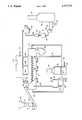
- Feeder hopper 10is operably connected with a size reduction means such as a pug mill, hammer mill or other type of grinder 11 to reduce the particle size of the contaminated soil to a relative small size for processing in the remainder of the system.
- a size reduction meanssuch as a pug mill, hammer mill or other type of grinder 11 to reduce the particle size of the contaminated soil to a relative small size for processing in the remainder of the system.
- the soilwill have a tendency to "dry out” on the surface and form a hard barrier whereby vaporizable components are trapped within the center of the large particle and will not be released during the treating process.
- the soil particlesAfter the soil is reduced in particle size to a particle size of preferably less than 1/8 of an inch in diameter, the soil particles then drop through the bottom of the size reduction unit 11 onto screen or mesh 12. The screen or mesh ensure that no large soil particles pass through the system. The thus screened soil particles then continue down below screen 12 into storage bin 13.
- An appropriate slide valve, gate or other control meanscan be placed on the bottom of storage bin 13 to ensure that the proper amount of soil is passed through the system to ensure an appropriate residence time for the removal of the vaporizable components from the contaminated soil.
- Conveyor 15can be any type of a conventional conveyor such as a belt conveyor, an auger conveyor, or the like. Conveyor 15 then moves the contaminated soil particles upwardly to above the discharge chute 16 which is in open communication with the interior of treatment vessel 17.
- Treatment vessel 17is preferably a horizontally mounted elongated treatment vessel that has a heat source whereby the contaminated soil particles can be conveyed through the treatment vessel while the particles are being subjected to heating by indirect heat exchange.
- treatment vessel 17can be a long cylindrical treatment vessel with an appropriate indirect heat exchange apparatus disposed therein.
- at least one heated auger conveyorcan be utilized within the treatment vessel 17 to convey and heat the contaminated particles as they move through treatment vessel 17. More preferrably there will be a pair of heated augers disposed in said treatment vessel.
- heated auger conveyors 18are depicted in the drawing to illustrate one method of heating and conveying the contaminated soil particles along the path of the treatment vessel 17.
- the heated auger conveyorscan be of the type supplied by the Denver Equipment Company of Colorado Springs, Colo. under the mark "holo-flite". These types of heated auger conveyors are more fully disclosed in U.S. Pat. Nos. 2,731,241 and 2,753,159. Such heated auger conveyors provide for an internally arranged passageway through which a heated heat transfer material such as hot oil can be pumped.
- the apparatus of the instant inventionprovides for an oil heater and an oil pump for heating the heat transfer oil and pumping it through the auger.
- hot oil line 19is connected to the end of the heated auger 18 for passing hot heat transfer oil through the internal passageway of the auger. As the hot transfer oil passes through the auger, heat is transferred from the hot transfer oil to the contaminated soil that is moved along by means of the rotating auger. For thermal efficiency, the hot oil flows countercurrent to the movement of the contaminated soil in treatment vessel 17.
- the vaporizable soil contaminatesare vaporized and are withdrawn from the treatment vessel by means of vapor withdrawal lines 20a, 20b and 20c. It will be appreciated that a plurality of vapor withdrawal lines are shown in the Figure, however, the presence of a plurality of vapor withdrawal lines is a preferred embodiment. In any case, however, at least one such vapor removal line must be present.
- the vapor removal linesall are in direct communication with vapor header 21 which passes the withdrawn vapor to downstream processing equipment which will be discusssed hereinafter.
- Hot oilis removed from heated auger conveyors 18 by means of hot oil return line 22.
- the effectiveness of the instant inventionmay be enhanced by jacketing treatment vessel 17 with a jacket that can also be filled with hot oil to provide further indirect heat transfer of heat into the contaminated soil as it passes through treatment vessel 17.
- hot oilcan be pumped through the jacket surrounding the treatment vessel 17 by means of jacket hot oil inlet 23.
- jacket hot oil inlet 23As the hot oil flows through the jacket surrounding treatment vessel 17, heat energy passes through the wall of the jacket into the contaminated soil within the vessel as it is moved through the vessel by means of the heated auger conveyors 18.
- the hot oilcan be removed from the jacket surrounding treatment vessel 17 by means of jacket hot oil return line 24.
- the relatively low pressure jacket hot oil in jacket hot oil return line 24can be passed to an appropriate hot oil surge tank 25 where it is stored for reheating in the equipment described below. Since there is a tendency for most hot oil used as heat transfer to oxidize, it is preferred to provide a blanket of nitrogen above the hot oil in the surge tank 25. Nitrogen can be added to provide such a blanket through nitrogen line 26.
- heating oil for the systemcan be withdrawn from the bottom of surge tank 25 by means of surge line 27 and that oil can be combined with the oil from hot oil line 22 and passed to supply line 28.
- Heating oil in supply line 28feeds oil pump 29 which discharges oil into oil heater 30.
- Oil heater 30has appropriate heating coils 31 disposed therein.
- Heater 30can be any conventional type of heater that is fired with an appropriate fuel which is added along with oxygen through appropriate feed lines into burner 32. Combustion gases generated in conventional heater 30 are removed and vented to the atmosphere through stack 33. The thus heated oil is then withdrawn from heater 30 and passed by means of hot oil supply line 34 for recirculation through the system.
- Gases that are gathered in vapor header line 21are transported to downstream equipment for processing and disposal.
- the gasescan be treated to remove dust and particulate matter. They can also be passed through condensers to condense out and recover the vaporized contaminates.
- item 35can be a condenser and/or an optional oil-water separator 35.
- the purpose of the oil-water separator 35is to allow for the "knock out" of condensed water and contaminates that may be condensed as the temperature of gases in vapor header line 21 decrease.
- Oil-water separator 35is a conventional oil-water separator which provides for a water sump line 36 for removing condensed water and an oil sump line 37 for removing oil from the separator.
- demister 39is optional piece of equipment and can be either eliminated or bypassed if the contaminants that are removed from the contaminated soil are so volatile that there is no appreciable condensation as they are removed from the treatment vessel.
- the vaporscan also be passed through filter inlet line 40 to a conventional filter 41. It will be appreciated that when contaminated soil is treated in the manner disclosed that there is a likelihood that dust and other particulate matter will be carried over through the vapor transfer lines. Therefore, it is preferred to utilize filters 41 or some other type of particulate matter removal appartus to remove the dust particles or particulate matter before the vaporized stream is passed to a blower. It will be appreciated of course that filter 41 can be utilized along with other types of dust removal equipment such as cyclones and the like for removing the particulate matter. Following the treatment in filter 41, the vaporized material then passes through suction line 42 into blower 43.
- filter 41 or a cyclone separatorcan be disposed upstream of any vapor treatment equipment.
- a cyclone separatormay be disposed in vapor header 21 before any effort is made to condense out any of the vaporized components.
- Blower 43is a conventional piece of equipment that will pull a suction on the upstream vapor gathering system. Since the overall system is to remove hazardous contaminants from contaminated soil, the system is preferably operated so that there is a slight vacuum exerted on the upstream vapor gathering and handling components. Therefore, by pulling a slight vacuum on the upstream vapor gathering and treatment apparatus, there will be a slight vacuum exerted inside the treatment vessel 17, along with the vapor gathering lines, the oil-water separator, demister, filters and the like. By using this slight vacuum, there will be little or no leakage of the vaporized contaminants or dust from the treatment vessel or other equipment into the atmosphere.
- the vacuumallows for the controlled intake of air into the interior of treatment vessel 17 with appropriate control means whereby the system can be operated without the danger of fire or explosion.
- the blowerwill be sized and operated in such a fashion that the interior of treatment vessel 17 will have a vacuum of at least one inch of water.
- the vapor streamexits blower 43 through exhaust line 44 and is then passed to a vapor disposal system.
- a preferred vapor disposal system for disposing of the vaporized contaminants from the contaminated soilis a conventional incinerator depicted as incinerator 45.
- vaporized contaminantsalong with air and other gases, enter the incinerator through blower exhaust line 44 and are then incinerated by means of a conventional burner disposed within incinerator 45.
- Air for the incineratoris added by means of air line 46 and fuel can be added in the form of any conventional fuel such as natural gas, propane and the like through gas line 47. It will be appreciated that when high levels of volatile combustible contaminants are present in the gaseous mixture added to the incinerator that additional air must be added through air line 46.
- incinerator 45is rather straight-forward and will include conventional combustion control devices to ensure that there is a complete combustion of the contaminants inside the incinerator whereby exhaust gas which is exhausted from the incinerator through stack 48 is a mixture of carbon dioxide, nitrogen and oxygen. It will be appreciated that an excess of air will be present in the incinerator to ensure complete combustion of the fuel and contaminants. It will of course be understood that where environmental concerns require that the exhaust gas in stack 48 can be passed to other gas treatment apparatus such as scrubbers and the like. If desired, some of the waste heat from the gases exiting through stack 48 can be reclaimed by means of heat exchangers and the like.
- the thus treated soilwill exit treatment vessel 17 through discharge flume 49 and can be conveniently dumped into hopper 50 for removal from the equipment and transport to some area remote from the equipment.
- the treated soil that is ultimately removed from hopper 50will contain little or no detectable contaminates. Therefore, it is safe to remove the treated soil from hopper 50 and return it directly to the hole from which it may have been excavated from.
- the consistency of the treated soilis a dry fine powdery material.
- Periodic samples of the material exiting through discharge flume 49should be utilized to ensure that the treatment vessel 17 is operated under the proper residence time and temperature conditions.
- a residence time of coursecan be controlled by controlling the variable speed heated auger conveyor rotation.
- the speed of the augersis within the skill of the art and commercially available control devices are not shown in the figures.
- the speed of the augercan be decreased to increase the residence time within treatment vessel 17.
- the temperature of the hot oil flowing through the heated auger conveyors 18 as well as through the optional jackets surrounding treatment vessel 17can be increased. It will be appreciated that the oil temperature that is passed through the auger conveyor will be above the boiling point of the contaminants to be removed.
- an oil temperature of between about 400° F. and about 700° F.are sufficient to remove most contaminants such as gasoline, diesel oil, cleaning solvents and the like. It has also been found that a residence time of at least 20 minutes is desirable for treating the contaminated soil to remove the above mentioned components.
- the residence time of the soil in treatment vessel 17is controlled by varying the auger rotation speed. It will however be appreciated that the proper adjustment of temperature and residence time is well within the skill of the art and can be adjusted by an operator having normal skill in the art in operating such equipment.
- an oxygen analyzeris disposed in vapor header 21. This analyzer has been depicted as analyzer 51 in the drawing. The output from analyzer 51 is passed to a control unit and controller with the output of such control unit and controller controlling the amount of ambient air that is pulled in to the treatment vessel.
- the control unit and controller 52can be any conventional controller such as Servomex Model 1100A controller with the output of such controller being used to control butterfly valves 53 on air valves 54 which control the amount of air that is allowed to be pulled into the interior of treatment vessel 17 through air ports 55.
- controller 52can be programed to ensure that the amount of oxygen that is detected by analyzer 51 is well outside that predetermined range. Once that range is predetermined, the controller 52 can be conventionally programed to control butterfly valves 53 to ensure that sufficient air is pulled into the interior of treatment vessel 17 to ensure that no hazardous condition exists within the interior of treatment vessel 17 or the vapor handling lines.
- an inert gassuch as nitrogen, carbon dioxide and the like can be added to treatment vessel 17 through gas lines 56a, 56b or 56c.
- the amount of inert gas addedis controlled by controller 52. In carrying out the invention, the amount of inert gas added is kept to a minimum for economic reasons.
- the present inventionthus provides and improved and safe method and apparatus for decontaminating soil that is contaminated with vaporizable contaminants.
- the operatorwill select the range of potentially hazardous mixtures of the vaporized contaminate and air and set controller unit 52 to control air valves 54 whereby the hazardous mixtures of vaporized contaminates and air, as detected by analyzer 51 are well outside the dangerous range. Thereafter, the operator will make periodic samplings of the treated soil that is discharged through discharge flume 49 and make appropriate adjustments in the residence time and temperatures within treatment vessel 17 to ensure the desired removal of the vaporizable contaminants from the soil as it is discharged through discharge flume 49.
Landscapes
- Physics & Mathematics (AREA)
- Thermal Sciences (AREA)
- Life Sciences & Earth Sciences (AREA)
- Soil Sciences (AREA)
- Engineering & Computer Science (AREA)
- Environmental & Geological Engineering (AREA)
- Processing Of Solid Wastes (AREA)
Abstract
Description
Claims (14)
Priority Applications (3)
| Application Number | Priority Date | Filing Date | Title |
|---|---|---|---|
| US07/748,862US5117771A (en) | 1991-08-23 | 1991-08-23 | Method and apparatus to decontaminate soil |
| AU24955/92AAU2495592A (en) | 1991-08-23 | 1992-08-24 | Method and apparatus to decontaminate soil |
| PCT/US1992/007132WO1993004319A1 (en) | 1991-08-23 | 1992-08-24 | Method and apparatus to decontaminate soil |
Applications Claiming Priority (1)
| Application Number | Priority Date | Filing Date | Title |
|---|---|---|---|
| US07/748,862US5117771A (en) | 1991-08-23 | 1991-08-23 | Method and apparatus to decontaminate soil |
Publications (1)
| Publication Number | Publication Date |
|---|---|
| US5117771Atrue US5117771A (en) | 1992-06-02 |
Family
ID=25011247
Family Applications (1)
| Application Number | Title | Priority Date | Filing Date |
|---|---|---|---|
| US07/748,862Expired - Fee RelatedUS5117771A (en) | 1991-08-23 | 1991-08-23 | Method and apparatus to decontaminate soil |
Country Status (3)
| Country | Link |
|---|---|
| US (1) | US5117771A (en) |
| AU (1) | AU2495592A (en) |
| WO (1) | WO1993004319A1 (en) |
Cited By (23)
| Publication number | Priority date | Publication date | Assignee | Title |
|---|---|---|---|---|
| US5253597A (en)* | 1992-06-18 | 1993-10-19 | Chemical Waste Management, Inc. | Process for separating organic contaminants from contaminated soils and sludges |
| US5325605A (en)* | 1992-10-14 | 1994-07-05 | Carew E Bayne | Method and apparatus for waste treatment |
| US5337684A (en)* | 1992-10-27 | 1994-08-16 | Summers Burg W | Material decontamination apparatus and method |
| US5655465A (en)* | 1992-12-18 | 1997-08-12 | Tox Free Systems, Inc. | Treatment of toxic wastes |
| US5988947A (en)* | 1997-11-04 | 1999-11-23 | Bruso; Bruce L. | Multi-section soil remediation device |
| US6582610B2 (en) | 2001-06-27 | 2003-06-24 | Varco I/P, Inc. | Concrete grindings reclamation system |
| US6644222B1 (en)* | 1999-10-04 | 2003-11-11 | Nederlandse Organisatie Voor Toegepast-Natuurwetenschappelijk Onderzoek Tno | System for continuous thermal combustion of matter, such as waste |
| US6688318B1 (en)* | 1996-10-16 | 2004-02-10 | Steve L. Clark | Process for cleaning hydrocarbons from soils |
| US20040134517A1 (en)* | 1996-10-16 | 2004-07-15 | Clark Steve L. | Process for cleaning hydrocarbons from soils |
| US20050080312A1 (en)* | 2003-10-14 | 2005-04-14 | Reinhardt Aldon R. | Environmental clean-up system |
| US20050260111A1 (en)* | 2004-05-20 | 2005-11-24 | Norman Arrison | Drilling mud remediation |
| US20060024135A1 (en)* | 2003-10-14 | 2006-02-02 | Vapor Tech, Inc. | Heavy oil extraction system |
| US20060075944A1 (en)* | 2004-10-07 | 2006-04-13 | Rineco Chemicalindustries, Inc. | Systems and methods for processing waste materials |
| US20060081506A1 (en)* | 2004-10-07 | 2006-04-20 | Rineco Chemical Industries, Inc. | Systems and methods for processing waste materials |
| US20060081504A1 (en)* | 2004-10-07 | 2006-04-20 | Rineco Chemical Industries, Inc. | Systems and methods for processing waste materials |
| US20060081505A1 (en)* | 2004-10-07 | 2006-04-20 | Rineco Chemical Industries, Inc. | Systems and methods for processing waste materials |
| US20070283905A1 (en)* | 2003-10-14 | 2007-12-13 | Vapor Tech, Inc. | Vapor generator with preheater and method of operating same |
| US20090031932A1 (en)* | 2006-03-02 | 2009-02-05 | Taiheiyo Cement Corporation | Method for Handling Substance from which Combustible Gas Volatilizes, Method for Producing Solid Fuel, Method for Storing Solid Fuel, Method for Using Solid Fuel, and Apparatus for Using Solid Fuel |
| US7669349B1 (en) | 2004-03-04 | 2010-03-02 | TD*X Associates LP | Method separating volatile components from feed material |
| US20100132210A1 (en)* | 2007-01-25 | 2010-06-03 | Inotec Gmbh Co. Holding Und Handels-Kg | Installation for drying organic matter |
| US8960108B1 (en)* | 2010-12-20 | 2015-02-24 | SilverStreet Group, LLC | System and method for cogeneration from mixed oil and inert solids, furnace and fuel nozzle for the same |
| CN108772414A (en)* | 2018-07-17 | 2018-11-09 | 贵州省环境科学研究设计院 | A kind of demercuration separator for modularization soil mercury removal device |
| CN108787728A (en)* | 2017-05-05 | 2018-11-13 | 北京华盛坤泰环境科技股份有限公司 | A kind of the Thermal desorption restorative procedure and system of organic material contaminated soil |
Families Citing this family (3)
| Publication number | Priority date | Publication date | Assignee | Title |
|---|---|---|---|---|
| DE4318661A1 (en)* | 1993-06-04 | 1994-12-08 | Fresenius Umwelttechnik Gmbh | Device and method for cleaning contaminated soil material |
| AU7483694A (en)* | 1993-09-01 | 1995-03-22 | Fsr Patented Technologies, Ltd. | Material cleansing device |
| BE1009472A3 (en)* | 1995-07-03 | 1997-04-01 | Applic Of Cleaning Tech On Soi | Method for thermo-biological cleansing of soil contaminated by organic compounds and device for the application of this method |
Citations (3)
| Publication number | Priority date | Publication date | Assignee | Title |
|---|---|---|---|---|
| US4738206A (en)* | 1986-09-16 | 1988-04-19 | Roy F. Weston, Inc. | Apparatus and method for low temperature thermal stripping of volatile organic compounds from soil |
| US4789332A (en)* | 1986-06-26 | 1988-12-06 | Aluminum Company Of America | Apparatus for removing volatiles from metal |
| US4974528A (en)* | 1989-12-08 | 1990-12-04 | Ryan-Murphy, Inc. | Method and apparatus for the treatment of contaminated soil |
- 1991
- 1991-08-23USUS07/748,862patent/US5117771A/ennot_activeExpired - Fee Related
- 1992
- 1992-08-24WOPCT/US1992/007132patent/WO1993004319A1/enactiveApplication Filing
- 1992-08-24AUAU24955/92Apatent/AU2495592A/ennot_activeAbandoned
Patent Citations (3)
| Publication number | Priority date | Publication date | Assignee | Title |
|---|---|---|---|---|
| US4789332A (en)* | 1986-06-26 | 1988-12-06 | Aluminum Company Of America | Apparatus for removing volatiles from metal |
| US4738206A (en)* | 1986-09-16 | 1988-04-19 | Roy F. Weston, Inc. | Apparatus and method for low temperature thermal stripping of volatile organic compounds from soil |
| US4974528A (en)* | 1989-12-08 | 1990-12-04 | Ryan-Murphy, Inc. | Method and apparatus for the treatment of contaminated soil |
Cited By (36)
| Publication number | Priority date | Publication date | Assignee | Title |
|---|---|---|---|---|
| US5253597A (en)* | 1992-06-18 | 1993-10-19 | Chemical Waste Management, Inc. | Process for separating organic contaminants from contaminated soils and sludges |
| US5453562A (en)* | 1992-06-18 | 1995-09-26 | Chemical Waste Management Inc. | Process for removing volatile components from soils and sludges contaminated with hazardous and radioactive materials |
| US5325605A (en)* | 1992-10-14 | 1994-07-05 | Carew E Bayne | Method and apparatus for waste treatment |
| US5337684A (en)* | 1992-10-27 | 1994-08-16 | Summers Burg W | Material decontamination apparatus and method |
| US5655465A (en)* | 1992-12-18 | 1997-08-12 | Tox Free Systems, Inc. | Treatment of toxic wastes |
| US6688318B1 (en)* | 1996-10-16 | 2004-02-10 | Steve L. Clark | Process for cleaning hydrocarbons from soils |
| US20040134517A1 (en)* | 1996-10-16 | 2004-07-15 | Clark Steve L. | Process for cleaning hydrocarbons from soils |
| US7338563B2 (en) | 1996-10-16 | 2008-03-04 | Clark Steve L | Process for cleaning hydrocarbons from soils |
| US5988947A (en)* | 1997-11-04 | 1999-11-23 | Bruso; Bruce L. | Multi-section soil remediation device |
| US6644222B1 (en)* | 1999-10-04 | 2003-11-11 | Nederlandse Organisatie Voor Toegepast-Natuurwetenschappelijk Onderzoek Tno | System for continuous thermal combustion of matter, such as waste |
| US6582610B2 (en) | 2001-06-27 | 2003-06-24 | Varco I/P, Inc. | Concrete grindings reclamation system |
| US7293532B2 (en) | 2003-10-14 | 2007-11-13 | Goodfield Energy Corp. | Heavy oil extraction system |
| US20070283905A1 (en)* | 2003-10-14 | 2007-12-13 | Vapor Tech, Inc. | Vapor generator with preheater and method of operating same |
| US7721679B2 (en) | 2003-10-14 | 2010-05-25 | Goodfield Energy Corporation | Vapor generator with preheater and method of operating same |
| US20050080312A1 (en)* | 2003-10-14 | 2005-04-14 | Reinhardt Aldon R. | Environmental clean-up system |
| US7228822B2 (en) | 2003-10-14 | 2007-06-12 | Goodfield Energy Corporation | Vapor generator using pre-heated injected water |
| US20060024135A1 (en)* | 2003-10-14 | 2006-02-02 | Vapor Tech, Inc. | Heavy oil extraction system |
| US8020313B2 (en) | 2004-03-04 | 2011-09-20 | TD*X Associates LP | Method and apparatus for separating volatile components from feed material |
| US7669349B1 (en) | 2004-03-04 | 2010-03-02 | TD*X Associates LP | Method separating volatile components from feed material |
| US20050260111A1 (en)* | 2004-05-20 | 2005-11-24 | Norman Arrison | Drilling mud remediation |
| US20060075944A1 (en)* | 2004-10-07 | 2006-04-13 | Rineco Chemicalindustries, Inc. | Systems and methods for processing waste materials |
| US7341155B2 (en) | 2004-10-07 | 2008-03-11 | Rineco Chemical Industries, Inc. | Systems and methods for processing waste materials |
| US7421959B2 (en) | 2004-10-07 | 2008-09-09 | Rineco Chemical Industries, Inc. | Systems and methods for processing waste materials |
| US8561802B2 (en) | 2004-10-07 | 2013-10-22 | Rineco Chemical Industries, Inc. | Systems and methods for processing waste materials |
| US20060081504A1 (en)* | 2004-10-07 | 2006-04-20 | Rineco Chemical Industries, Inc. | Systems and methods for processing waste materials |
| US20060081506A1 (en)* | 2004-10-07 | 2006-04-20 | Rineco Chemical Industries, Inc. | Systems and methods for processing waste materials |
| US20060081505A1 (en)* | 2004-10-07 | 2006-04-20 | Rineco Chemical Industries, Inc. | Systems and methods for processing waste materials |
| US8453584B2 (en)* | 2006-03-02 | 2013-06-04 | Taiheiyo Cement Corporation | Method for handling substance from which combustible gas volatilizes, method for producing solid fuel, method for storing solid fuel, method for using solid fuel, and apparatus for using solid fuel |
| US20090031932A1 (en)* | 2006-03-02 | 2009-02-05 | Taiheiyo Cement Corporation | Method for Handling Substance from which Combustible Gas Volatilizes, Method for Producing Solid Fuel, Method for Storing Solid Fuel, Method for Using Solid Fuel, and Apparatus for Using Solid Fuel |
| US20100132210A1 (en)* | 2007-01-25 | 2010-06-03 | Inotec Gmbh Co. Holding Und Handels-Kg | Installation for drying organic matter |
| US8561314B2 (en)* | 2007-01-25 | 2013-10-22 | Inotec Gmbh Co. Holding Und Handels-Kg | Installation for drying organic matter |
| US8960108B1 (en)* | 2010-12-20 | 2015-02-24 | SilverStreet Group, LLC | System and method for cogeneration from mixed oil and inert solids, furnace and fuel nozzle for the same |
| US10132496B1 (en) | 2010-12-20 | 2018-11-20 | Silver Street Group, LLC | System and method for cogeneration from mixed oil and inert solids, furnace and fuel nozzle for the same |
| CN108787728A (en)* | 2017-05-05 | 2018-11-13 | 北京华盛坤泰环境科技股份有限公司 | A kind of the Thermal desorption restorative procedure and system of organic material contaminated soil |
| CN108772414A (en)* | 2018-07-17 | 2018-11-09 | 贵州省环境科学研究设计院 | A kind of demercuration separator for modularization soil mercury removal device |
| CN108772414B (en)* | 2018-07-17 | 2024-03-26 | 贵州省环境科学研究设计院 | Mercury removal and separation device for modularized soil mercury removal device |
Also Published As
| Publication number | Publication date |
|---|---|
| WO1993004319A1 (en) | 1993-03-04 |
| AU2495592A (en) | 1993-03-16 |
Similar Documents
| Publication | Publication Date | Title |
|---|---|---|
| US5117771A (en) | Method and apparatus to decontaminate soil | |
| US4715965A (en) | Method for separating and recovering volatilizable contaminants from soil | |
| US4738206A (en) | Apparatus and method for low temperature thermal stripping of volatile organic compounds from soil | |
| US5188041A (en) | Apparatus and method for low temperature thermal stripping of volatile organic compounds from soil and waste materials with non-oxidative co-current gases | |
| US5292429A (en) | Process for recovery and treatment of a diverse waste stream | |
| AU727756B2 (en) | Process and apparatus for treating process streams from a system for separating constituents from contaminated material | |
| US5302254A (en) | Process and plant for the thermolysis of industrial and/or urban waste | |
| US5523060A (en) | Apparatus for retorting material | |
| US5072674A (en) | Apparatus and method for low temperature thermal stripping of volatile organic compounds from soil with non-oxidative cross-sweep gases | |
| WO1990011475A1 (en) | Thermal treatment process for organically contaminated material | |
| US4793937A (en) | Method and apparatus for separating contaminants from fluidizable solids | |
| US5337684A (en) | Material decontamination apparatus and method | |
| EA013334B1 (en) | An improved apparatus for treatment of drill cuttings | |
| US6658757B2 (en) | Method and apparatus for separating hydrocarbons from material | |
| US5514286A (en) | Thermal desorption unit | |
| US5176087A (en) | Apparatus and method for low temperature thermal stripping of volatile organic compounds from soil and waste materials with non-oxidative cross-sweep gases | |
| US5273629A (en) | Method and apparatus for separating contaminants from fluidizable solids and converting the contaminate to less toxic or non-toxic materials | |
| EP0331842A1 (en) | Process and apparatus for recovery of oil | |
| JPH0842827A (en) | Method and equipment for thermally treating material having vaporizable substance | |
| EP0561955B1 (en) | A method of continuously decontaminating a material, and an assembly for carrying out the method | |
| WO2016105608A1 (en) | Feedback loop control for soil evaporative desorption | |
| US6416567B1 (en) | Removal of mercury from waste materials | |
| US5195887A (en) | Remediation of hydrocarbons from soils, sand and gravel | |
| USRE33776E (en) | Apparatus and method for low temperature thermal stripping of volatile organic compounds from soil | |
| Kim et al. | Development of low temperature thermal desorption system and remediation of soil contaminated with petroleum hydrocarbon |
Legal Events
| Date | Code | Title | Description |
|---|---|---|---|
| AS | Assignment | Owner name:VANGUARD ENVIRONMENTAL, INC. A LA CORPORATION Free format text:ASSIGNMENT OF ASSIGNORS INTEREST.;ASSIGNOR:SUMMERS, BURG W.;REEL/FRAME:005951/0933 Effective date:19910830 | |
| REMI | Maintenance fee reminder mailed | ||
| LAPS | Lapse for failure to pay maintenance fees | ||
| FP | Lapsed due to failure to pay maintenance fee | Effective date:19960605 | |
| AS | Assignment | Owner name:TRANSTECHNOLOGY LTD., JAPAN Free format text:MERGER;ASSIGNOR:JATCO CORPORATION;REEL/FRAME:013362/0795 Effective date:20021226 | |
| AS | Assignment | Owner name:JATCO TRANSTECHNOLOGY LTD., JAPAN Free format text:CHANGE OF NAME;ASSIGNOR:TRANSTECHNOLOGY LTD.;REEL/FRAME:013372/0631 Effective date:19991001 | |
| AS | Assignment | Owner name:JATCO LTD, JAPAN Free format text:CHANGE OF NAME & ADDRESS;ASSIGNOR:JATCO TRANSTECHNOLOGY LTD.;REEL/FRAME:013438/0834 Effective date:20020404 | |
| AS | Assignment | Owner name:JATCO LTD, JAPAN Free format text:CHANGE OF NAME & ADDRESS;ASSIGNOR:JATCO TRANSTECHNOLOGY LTD.;REEL/FRAME:013429/0230 Effective date:20020404 | |
| STCH | Information on status: patent discontinuation | Free format text:PATENT EXPIRED DUE TO NONPAYMENT OF MAINTENANCE FEES UNDER 37 CFR 1.362 |