US5117706A - Backlash-free drive for the infeed mechanism of a microtome - Google Patents
Backlash-free drive for the infeed mechanism of a microtomeDownload PDFInfo
- Publication number
- US5117706A US5117706AUS07/725,781US72578191AUS5117706AUS 5117706 AUS5117706 AUS 5117706AUS 72578191 AUS72578191 AUS 72578191AUS 5117706 AUS5117706 AUS 5117706A
- Authority
- US
- United States
- Prior art keywords
- nut
- spindle
- drive
- threaded spindle
- specimen holder
- Prior art date
- Legal status (The legal status is an assumption and is not a legal conclusion. Google has not performed a legal analysis and makes no representation as to the accuracy of the status listed.)
- Expired - Lifetime
Links
- 230000006835compressionEffects0.000claimsdescription8
- 238000007906compressionMethods0.000claimsdescription8
- 229940090441infedDrugs0.000claimsdescription3
- 230000002093peripheral effectEffects0.000claimsdescription2
- 230000000284resting effectEffects0.000claimsdescription2
- 230000000694effectsEffects0.000abstractdescription2
- 238000004519manufacturing processMethods0.000description4
- 238000005520cutting processMethods0.000description2
- 230000001360synchronised effectEffects0.000description2
- 238000010420art techniqueMethods0.000description1
- 238000005352clarificationMethods0.000description1
- 230000008030eliminationEffects0.000description1
- 238000003379elimination reactionMethods0.000description1
- 230000002349favourable effectEffects0.000description1
- 238000010562histological examinationMethods0.000description1
- 238000009877renderingMethods0.000description1
Images


Classifications
- B—PERFORMING OPERATIONS; TRANSPORTING
- B23—MACHINE TOOLS; METAL-WORKING NOT OTHERWISE PROVIDED FOR
- B23Q—DETAILS, COMPONENTS, OR ACCESSORIES FOR MACHINE TOOLS, e.g. ARRANGEMENTS FOR COPYING OR CONTROLLING; MACHINE TOOLS IN GENERAL CHARACTERISED BY THE CONSTRUCTION OF PARTICULAR DETAILS OR COMPONENTS; COMBINATIONS OR ASSOCIATIONS OF METAL-WORKING MACHINES, NOT DIRECTED TO A PARTICULAR RESULT
- B23Q5/00—Driving or feeding mechanisms; Control arrangements therefor
- B23Q5/54—Arrangements or details not restricted to group B23Q5/02 or group B23Q5/22 respectively, e.g. control handles
- B23Q5/56—Preventing backlash
- F—MECHANICAL ENGINEERING; LIGHTING; HEATING; WEAPONS; BLASTING
- F16—ENGINEERING ELEMENTS AND UNITS; GENERAL MEASURES FOR PRODUCING AND MAINTAINING EFFECTIVE FUNCTIONING OF MACHINES OR INSTALLATIONS; THERMAL INSULATION IN GENERAL
- F16H—GEARING
- F16H25/00—Gearings comprising primarily only cams, cam-followers and screw-and-nut mechanisms
- F16H25/18—Gearings comprising primarily only cams, cam-followers and screw-and-nut mechanisms for conveying or interconverting oscillating or reciprocating motions
- F16H25/20—Screw mechanisms
- F16H25/2003—Screw mechanisms with arrangements for taking up backlash
- F16H25/2006—Screw mechanisms with arrangements for taking up backlash with more than one nut or with nuts consisting of more than one bearing part
- G—PHYSICS
- G01—MEASURING; TESTING
- G01N—INVESTIGATING OR ANALYSING MATERIALS BY DETERMINING THEIR CHEMICAL OR PHYSICAL PROPERTIES
- G01N1/00—Sampling; Preparing specimens for investigation
- G01N1/02—Devices for withdrawing samples
- G01N1/04—Devices for withdrawing samples in the solid state, e.g. by cutting
- G01N1/06—Devices for withdrawing samples in the solid state, e.g. by cutting providing a thin slice, e.g. microtome
- Y—GENERAL TAGGING OF NEW TECHNOLOGICAL DEVELOPMENTS; GENERAL TAGGING OF CROSS-SECTIONAL TECHNOLOGIES SPANNING OVER SEVERAL SECTIONS OF THE IPC; TECHNICAL SUBJECTS COVERED BY FORMER USPC CROSS-REFERENCE ART COLLECTIONS [XRACs] AND DIGESTS
- Y10—TECHNICAL SUBJECTS COVERED BY FORMER USPC
- Y10T—TECHNICAL SUBJECTS COVERED BY FORMER US CLASSIFICATION
- Y10T74/00—Machine element or mechanism
- Y10T74/19—Gearing
- Y10T74/1987—Rotary bodies
- Y10T74/19893—Sectional
- Y10T74/19898—Backlash take-up
- Y10T74/19902—Screw and nut
Definitions
- the inventionrelates to a backlash-free drive for the infeed mechanism of a microtome, comprising a threaded spindle which is mounted so as to be rotatable but not axially shiftable and a spindle nut in cooperation therewith and connected via a gear to a specimen holder which can be infed in the direction of a blade.
- a basic requirement for histological examinationsis that thickness of cut remain constant. Thickness of cut must remain constant during periods of frequent use of the microtome as well as following lengthy periods of disuse. Ambient temperature should likewise have no effect on thickness of cut.
- the design and implementation of the infeed mechanismwhich is also known as a micrometer mechanism, is of decisive importance in this context.
- the prior art designemployed a screw gear, as shown in FIGS. 1 and 2 for purposes of clarification. This arrangement made use of a two-point or three-point heel acting primarily on the thread crests to prevent axial backlash of threads. However, even slight conicity of the spindle thread renders this point arrangement ineffective, as a result of which incrementation size and hence uniform thickness of cut are no longer ensured; the resulting cuts are thus of varying thickness.
- the object of the present inventionis to provide a backlash-free drive for the infeed mechanism of a microtome, this mechanism being self-adjusting and to a large extent maintenance-free.
- the spindle nutconsists of two nut elements which are non-rotatable but can be shifted in an axial direction relative to one another and are spring-loaded against one another.
- the spring loading of the nut elementsis preferably effected by means of a compression spring, in particular, by means of a leaf spring or sinuous spring or at least a helical compression spring.
- the nut elementsare preferably connected to one another in the direction of rotation by means of a pin attached to one of them and engaging in a groove of the other.
- the resulting precision screw gearis self-adjusting for axial backlash, which occurs when the screw flanks become worn; it ensures reproducible incrementation movements in the ⁇ m range for feed from the object holding device to the blade and allows greater tolerances in manufacturing.
- connection between the specimen holder and the spindle nutis preferably effected via a nut element by means of two ball bearings spring-loaded against one another by a compression spring. It has been found suitable to provide at least one plain bearing between the screw spindle and the nut element connected via a gear to the specimen holder, with the plain bearing preferably being adjacent to the corresponding nut element. According to a particularly preferred embodiment, a plain bearing is provided on both sides of the thread of the nut element connected via a gear to the specimen holder. This allows stabilized positioning accuracy for radial-axial loads as well as for coarse and fine adjustments, without conicity of the spindle thread leading to problems. It is appropriate for the plain bearings to consist of a cylindrical peripheral piece of the threaded spindle in cooperation with a cylindrical inner wall of the nut element.
- the inventionachieves these objects by restricting the end position for axial movement by means of at least one fence acting in an end area of the spindle nut feed in the direction of spindle circumference. It is appropriate to design this fence such that at least one of the nut elements contains a first fence element on its front end which is disposed away from the other nut element, said fence element engaging after a predetermined number of spindle rotations with a second fence element located on the threaded spindle itself. The thread geometry is thus protected from deformation.
- a frictional spring-plate clutchprotects the micrometer mechanism from excessive driving torque.
- the nut element fixed to the specimen holder by means of the ball bearingsis secured via a first frictional clutch against twisting relative to the specimen holder until a first given torque has been exceeded.
- the first frictional clutchis preferably a sinuous spring resting against the shoulder of the nut element, said sinuous spring being supported on the outer race of one of the ball bearings.
- the threaded spindleis secured via a second frictional clutch against twisting relative to a stationary part of the microtome until a second specified torque has been exceeded.
- a prior art automatic feed deviceacts on the nut element rotatably mounted at the specimen holder--this automatic feed device rotating against the resistance of the first frictional clutch while the threaded spindle remains motionless under the action of the second frictional clutch--and if the threaded spindle itself is connected to a second feed drive preferably used for rapid feed, with manual drive being suitable, rapid feed and automatic incrementation movement can readily be achieved while simultaneously avoiding the excessive driving torque mentioned above. It has also proven favorable to fix the threaded spindle in an axial direction relative to a stationary part of the microtome by means of at least one needle roller bearing acting in an axial direction. It is preferable to use two needle roller bearings to ensure that the axial mounting of the threaded spindle is free from backlash.
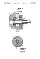
- FIG. 1shows a longitudinal section of a prior art infeed mechanism of a microtome in which the horizontal feed for the infeed movement between blade and object is effected by means of a screw gear on which the threaded spindle and spindle nut are mated by means of a radial load so as to be nearly free from backlash.
- FIG. 2shows a cross section through the screw gear of the prior art infeed mechanism shown in FIG. 1, with the remaining axial backlash of threads being compensated for by means of radially-disposed functional elements.
- FIG. 3shows a schematically simplified longitudinal section of an embodiment of a screw gear used for the infeed mechanism according to the invention.
- FIG. 4shows a longitudinal section through the infeed mechanism according to the invention, with parts which are not essential for an understanding having been omitted.
- a threaded spindle 1to which a spindle nut 2 is attached by means of a threaded joint.
- Spindle nut 2is fixed by means of two ball bearings 3, 4 to a specimen holder 5, which is only partially shown, such that the specimen holder is shifted in an axial direction but not rotated when spindle nut 2 is attached at the threaded joint.
- nut elements 2a and 2bare connected to one another so as to be non-rotatable but shiftable in an axial direction relative to one another.
- Nut elements 2a and 2bare spring-loaded against one another by means of a spring device 10, thus ensuring that nut element 2a and its threads rest against the right tooth flank of the spindle thread, as seen in FIG. 3, while nut element 2b and its threads rest against the left tooth flank of the spindle thread, as seen in FIG. 3, or vice versa, depending on whether spring device 10 acts as a compression spring, as in the case shown, or as a tension spring, as in the other case mentioned.
- spindle nut 1Portions of spindle nut 1 are provided with a spindle thread 8a or 8b.
- Spindle nut 1also contains two precision cylinder guideways 11 and 12, with guideway 11 being located between spindle thread portions 8a and 8b, and guideway 12 being located at the end of spindle 1 disposed towards the infeed mechanism.
- the diameter of precision cylinder guideway 11is greater than that of the spindle thread, while that of precision cylinder guideway 12 is smaller than that of the spindle thread, which serves to simplify the assembly of the parts.
- Precision cylinder guideways 11 and 12cooperate with precision cylinder bushes 13, 14, respectively, said precision cylinder bushes being located inside nut element 2a and imparting a centering function to the outer thread diameter of spindle thread 8b, such that any conicity over the length of this thread area 8a has no influence on the constancy of thickness of cut.
- Thread area 8b of threaded spindle 1engages with female thread 15 of nut element 2a, such that when threaded spindle 1 rotates, nut element 2a--which is radially mounted via deep-groove ball bearings 3 and 4--shifts the slider 16, which constitutes or supports the specimen holder.
- Sinuous spring 17spring-loads the two deep-groove ball bearings 3 and 4 in an axial direction such that a defined radial rotational movement of nut element 2a on threaded spindle 1 takes place without axial shifting relative to mobile slider 16, which transfers the infeed from the object to the blade.
- Deep-groove ball bearings 3 and 4are supported axially via spindle 1 on two needle roller bearings 18, 19 to take up axial alternation of load, with the axial needle roller bearings 18, 19 effecting an elimination of backlash.
- Needle roller bearing 18is held against a stationary part of the microtome by a collar 20 of threaded spindle 1 or a snap ring set in a corresponding groove of this spindle.
- needle roller bearing 19which is held against a stationary part--shown in FIG. 4 as reference number 21--by means of a drive pinion 22 for manual rapid drive attached to the end of threaded spindle 1 or by means of a lock-nut located therebetween which is not shown in the drawings.
- the drive pinionis held on threaded spindle 1 via a pin 23 or a plate screw so as to be non-rotatable.
- Sinuous spring 17also serves as a countersupport, its spring resistance being selected so as to prevent forward movement of slider 16 during the cutting process, which would pull the object towards the blade.
- An additional sinuous spring 24, which counteracts sinuous spring 17,is supported on a shoulder of nut element 2a as well as on the outer race of ball bearing 4, thereby forming the first frictional clutch. This clutch prevents nut element 2a from rotating with threaded spindle 1 when threaded spindle 1 is rotated via the drive pinion, thus preventing nut element 2a and the specimen holder from shifting in an axial direction.
- Friction disk 25which serves as a second frictional clutch, rests against the front end of drive pinion 22. Friction disk 25 prevents threaded spindle 1 from rotating when the microtome is switched to "automatic feed", this switching status being effected in what is a prior art technique via an automatic feed device 26 equipped with a ratchet clutch. Automatic feed device 26 acts directly upon nut element 2a and rotates same further by a certain amount for every cut which follows, depending on the desired feed.
- nut element 2bis screwed on to spindle thread area 8a to the left of nut element 2a and at a distance from same, this being effected by means of female thread 27 of nut element 2b.
- Nut element 2bis provided with a set screw 28 in its inwardly-directed end, said end area having a reduced outer diameter and overlapping the end area of nut element 2a.
- This set screwengages in a longitudinal slot 29 extending in an axial direction to threaded spindle 1 on the outer side of nut element 2a.
- the width of longitudinal slot 29 and the end of set screw 28 projecting into itare measured such that the set screw is positively locked in the longitudinal slot and can be shifted along it. Synchronous action is thus established between nut elements 2a and 2b.
- a leaf spring in the form of a sinuous spring or a helical compression springis provided as spring element 10 between the outwardly-directed front end of nut element 2a and the inwardly-directed front end of nut element 2b.
- This spring element 10spring-loads nut elements 2a and 2b against one another as shown more fully in FIG. 3.
- the embodiment described aboveprovides a precision screw gear which is self-adjusting with respect to axial backlash and ensures reproducible incrementation movements in the ⁇ m range between the blade, which is not shown, and the object holding device when the thread flanks show signs of wear.
- Protruding fence elementsare also provided on the front ends of nut elements 2a and 2b disposed away from one another, these elements comprising pins 30 and 31, respectively, in FIG. 4. These fence elements cooperate with fence elements 32 and 33, which are located on the front and rear areas of the threaded spindle, respectively, and comprise pins passing through threaded spindle 1 and protruding beyond its circumference. After a predetermined number of spindle rotations in a "forward direction", fence elements 30 and 32 meet in the circumferential direction. The furthest position to which nut elements 2a and 2b can be returned is restricted by fence elements 31 and 33, which likewise meet in the circumferenctial direction.
Landscapes
- Engineering & Computer Science (AREA)
- Mechanical Engineering (AREA)
- General Engineering & Computer Science (AREA)
- Life Sciences & Earth Sciences (AREA)
- Health & Medical Sciences (AREA)
- Chemical & Material Sciences (AREA)
- Analytical Chemistry (AREA)
- Biochemistry (AREA)
- General Health & Medical Sciences (AREA)
- General Physics & Mathematics (AREA)
- Immunology (AREA)
- Pathology (AREA)
- Physics & Mathematics (AREA)
- Sampling And Sample Adjustment (AREA)
- Transmission Devices (AREA)
- Devices For Use In Laboratory Experiments (AREA)
Abstract
Description
Claims (16)
Applications Claiming Priority (2)
| Application Number | Priority Date | Filing Date | Title |
|---|---|---|---|
| DE3727975 | 1987-08-21 | ||
| DE3727975ADE3727975C2 (en) | 1987-08-21 | 1987-08-21 | Backlash-free drive for the delivery mechanism of a microtome |
Related Parent Applications (1)
| Application Number | Title | Priority Date | Filing Date |
|---|---|---|---|
| US07348578Continuation | 1989-04-17 |
Publications (1)
| Publication Number | Publication Date |
|---|---|
| US5117706Atrue US5117706A (en) | 1992-06-02 |
Family
ID=6334223
Family Applications (1)
| Application Number | Title | Priority Date | Filing Date |
|---|---|---|---|
| US07/725,781Expired - LifetimeUS5117706A (en) | 1987-08-21 | 1991-07-03 | Backlash-free drive for the infeed mechanism of a microtome |
Country Status (6)
| Country | Link |
|---|---|
| US (1) | US5117706A (en) |
| EP (1) | EP0326607B1 (en) |
| JP (1) | JPH02500542A (en) |
| AT (1) | ATE68041T1 (en) |
| DE (2) | DE3727975C2 (en) |
| WO (1) | WO1989001579A1 (en) |
Cited By (5)
| Publication number | Priority date | Publication date | Assignee | Title |
|---|---|---|---|---|
| US5303606A (en)* | 1993-04-15 | 1994-04-19 | Kokinda Mark A | Anti-backlash nut having a free floating insert for applying an axial force to a lead screw |
| US5817810A (en)* | 1995-07-26 | 1998-10-06 | Mita Industrial Co., Ltd. | Tryptanthrine compounds |
| US20080000339A1 (en)* | 2006-07-03 | 2008-01-03 | Leica Microsystems Nussloch Gmbh | Crank Drive System Of A Shaft Of A Microtome |
| CN102094951A (en)* | 2010-12-21 | 2011-06-15 | 中国科学院国家天文台南京天文光学技术研究所 | Transmission device of precise displacement actuator |
| US20180163829A1 (en)* | 2016-12-12 | 2018-06-14 | Aktiebolaget Skf | Actuator |
Families Citing this family (13)
| Publication number | Priority date | Publication date | Assignee | Title |
|---|---|---|---|---|
| FR2657403B1 (en)* | 1990-01-19 | 1992-04-17 | Gravograph | ANTI-GAME NUT. |
| JPH04119777U (en)* | 1991-04-12 | 1992-10-27 | 光洋精工株式会社 | electric steering device |
| DE4135532A1 (en)* | 1991-10-28 | 1993-04-29 | Fibro Gmbh | POSITIONING DEVICE |
| DE4339071A1 (en)* | 1993-11-16 | 1995-05-18 | Walter Ganter | Microtome |
| FI102852B1 (en)* | 1995-06-05 | 1999-02-26 | Nokia Telecommunications Oy | Linear motion device |
| DE10210408B4 (en)* | 2002-03-09 | 2010-07-08 | Leica Biosystems Nussloch Gmbh | Microtome with feed device |
| DE102008064129B3 (en)* | 2008-12-19 | 2010-06-02 | Micromotion Gmbh | Spindle nut system for micro spindle drive, has clamping ring and nut halves, which comprise form-fit component e.g. rectangular projection and recess, which is formed for form-fit connection of system |
| US10100908B2 (en)* | 2012-11-30 | 2018-10-16 | Kuroda Precision Industries Ltd. | Shaft end adapter and ball screw assembly |
| DE102014005445B3 (en)* | 2014-04-11 | 2015-01-29 | Hans Heid | Microtome and method of operating a microtome |
| KR101944715B1 (en)* | 2016-12-29 | 2019-02-01 | 주식회사 만도 | An assembly of lead screw and Rear wheel steering system using the same |
| CN107351164B (en)* | 2017-08-07 | 2022-12-16 | 浙江省金华市科迪仪器设备有限公司 | Slicing machine |
| DE102017128522A1 (en) | 2017-12-01 | 2018-12-20 | Schaeffler Technologies AG & Co. KG | Ball Screw |
| CN109333638B (en)* | 2018-10-10 | 2020-10-02 | 江苏鑫世丰技术产权交易有限公司 | Cutter protection device for sponge cutting |
Citations (12)
| Publication number | Priority date | Publication date | Assignee | Title |
|---|---|---|---|---|
| US525780A (en)* | 1894-09-11 | Island | ||
| US2328732A (en)* | 1942-12-02 | 1943-09-07 | Mckinney Tool And Mfg Company | Universal backlash prevention device |
| US2345194A (en)* | 1942-01-09 | 1944-03-28 | Sundstrand Machine Tool Co | Feed screw mechanism |
| US2690682A (en)* | 1953-01-22 | 1954-10-05 | Collins Radio Co | Antibacklash control shaft |
| US2919596A (en)* | 1958-02-24 | 1960-01-05 | Gorton George Machine Co | Anti-backlash nut |
| US3001414A (en)* | 1959-03-13 | 1961-09-26 | Gen Electric Co Ltd | Anti-backlash devices |
| US3703835A (en)* | 1970-08-27 | 1972-11-28 | Oconnor Charles A | Means for taking up slack in lead screw devices |
| US4114470A (en)* | 1976-01-16 | 1978-09-19 | Perenco Limited | Relating to pressure fluid operated actuators |
| FR2394724A1 (en)* | 1977-06-13 | 1979-01-12 | Micro Controle | Drive mechanism for use in metrology - consists of threaded shaft with main and auxiliary nuts coupled by metallic bellows |
| GB2132310A (en)* | 1982-12-23 | 1984-07-04 | Yiu Ming Cheng | Machine tool apparatus |
| US4625608A (en)* | 1984-02-07 | 1986-12-02 | Parke, Davis & Company | Microtomes |
| GB2182786A (en)* | 1985-11-05 | 1987-05-20 | Parke Davis & Co | Microtome having specimen holder movable in two directions |
Family Cites Families (4)
| Publication number | Priority date | Publication date | Assignee | Title |
|---|---|---|---|---|
| US4068382A (en)* | 1977-03-03 | 1978-01-17 | Jankowiak Joseph E | Angle tangent micrometer |
| EP0132442A1 (en)* | 1977-08-31 | 1985-02-13 | Hans-Theodor Grisebach | Sprindle actuated positioning device |
| US4598621A (en)* | 1985-02-28 | 1986-07-08 | Parke, Davis & Company | Microtome having a handwheel for driving a specimen holder |
| DE3532895C1 (en)* | 1985-09-14 | 1986-05-07 | Parke, Davis & Co., Morris Plains, N.J. | Cutting and stretching device for a microtome |
- 1987
- 1987-08-21DEDE3727975Apatent/DE3727975C2/ennot_activeExpired - Fee Related
- 1988
- 1988-08-18DEDE8888907306Tpatent/DE3865304D1/ennot_activeExpired - Lifetime
- 1988-08-18EPEP88907306Apatent/EP0326607B1/ennot_activeExpired - Lifetime
- 1988-08-18ATAT88907306Tpatent/ATE68041T1/ennot_activeIP Right Cessation
- 1988-08-18WOPCT/EP1988/000739patent/WO1989001579A1/enactiveIP Right Grant
- 1988-08-18JPJP63505359Apatent/JPH02500542A/enactivePending
- 1991
- 1991-07-03USUS07/725,781patent/US5117706A/ennot_activeExpired - Lifetime
Patent Citations (12)
| Publication number | Priority date | Publication date | Assignee | Title |
|---|---|---|---|---|
| US525780A (en)* | 1894-09-11 | Island | ||
| US2345194A (en)* | 1942-01-09 | 1944-03-28 | Sundstrand Machine Tool Co | Feed screw mechanism |
| US2328732A (en)* | 1942-12-02 | 1943-09-07 | Mckinney Tool And Mfg Company | Universal backlash prevention device |
| US2690682A (en)* | 1953-01-22 | 1954-10-05 | Collins Radio Co | Antibacklash control shaft |
| US2919596A (en)* | 1958-02-24 | 1960-01-05 | Gorton George Machine Co | Anti-backlash nut |
| US3001414A (en)* | 1959-03-13 | 1961-09-26 | Gen Electric Co Ltd | Anti-backlash devices |
| US3703835A (en)* | 1970-08-27 | 1972-11-28 | Oconnor Charles A | Means for taking up slack in lead screw devices |
| US4114470A (en)* | 1976-01-16 | 1978-09-19 | Perenco Limited | Relating to pressure fluid operated actuators |
| FR2394724A1 (en)* | 1977-06-13 | 1979-01-12 | Micro Controle | Drive mechanism for use in metrology - consists of threaded shaft with main and auxiliary nuts coupled by metallic bellows |
| GB2132310A (en)* | 1982-12-23 | 1984-07-04 | Yiu Ming Cheng | Machine tool apparatus |
| US4625608A (en)* | 1984-02-07 | 1986-12-02 | Parke, Davis & Company | Microtomes |
| GB2182786A (en)* | 1985-11-05 | 1987-05-20 | Parke Davis & Co | Microtome having specimen holder movable in two directions |
Cited By (10)
| Publication number | Priority date | Publication date | Assignee | Title |
|---|---|---|---|---|
| US5303606A (en)* | 1993-04-15 | 1994-04-19 | Kokinda Mark A | Anti-backlash nut having a free floating insert for applying an axial force to a lead screw |
| US5817810A (en)* | 1995-07-26 | 1998-10-06 | Mita Industrial Co., Ltd. | Tryptanthrine compounds |
| US20080000339A1 (en)* | 2006-07-03 | 2008-01-03 | Leica Microsystems Nussloch Gmbh | Crank Drive System Of A Shaft Of A Microtome |
| US7900545B2 (en)* | 2006-07-03 | 2011-03-08 | Leica Biosystems Nussloch Gmbh | Crank drive system of a shaft of a microtome |
| CN102094951A (en)* | 2010-12-21 | 2011-06-15 | 中国科学院国家天文台南京天文光学技术研究所 | Transmission device of precise displacement actuator |
| CN102094951B (en)* | 2010-12-21 | 2013-01-09 | 中国科学院国家天文台南京天文光学技术研究所 | Transmission device of precise displacement actuator |
| US20180163829A1 (en)* | 2016-12-12 | 2018-06-14 | Aktiebolaget Skf | Actuator |
| CN108223737A (en)* | 2016-12-12 | 2018-06-29 | 斯凯孚公司 | Actuator |
| US10781899B2 (en)* | 2016-12-12 | 2020-09-22 | Aktiebolaget Skf | Actuator |
| CN108223737B (en)* | 2016-12-12 | 2024-02-13 | 伊维莱有限公司 | Actuator with a spring |
Also Published As
| Publication number | Publication date |
|---|---|
| EP0326607A1 (en) | 1989-08-09 |
| EP0326607B1 (en) | 1991-10-02 |
| DE3727975C2 (en) | 1995-10-19 |
| WO1989001579A1 (en) | 1989-02-23 |
| DE3727975A1 (en) | 1989-03-02 |
| JPH02500542A (en) | 1990-02-22 |
| ATE68041T1 (en) | 1991-10-15 |
| DE3865304D1 (en) | 1991-11-07 |
Similar Documents
| Publication | Publication Date | Title |
|---|---|---|
| US5117706A (en) | Backlash-free drive for the infeed mechanism of a microtome | |
| EP0095891B2 (en) | Devices for converting rotary movement into linear movement | |
| US5186068A (en) | Gear reducer with backlash eliminator | |
| DE10112570B4 (en) | Electrically actuated disc brake | |
| DE60000615T2 (en) | ACTUATING DEVICE WITH A COMPACT REDUCER | |
| US6158720A (en) | Anti-backlash nut assembly | |
| US5664457A (en) | Screw gear means and method for same | |
| NL1014064C2 (en) | Actuator and caliper. | |
| DE3606042A1 (en) | BEARING ARRANGEMENT | |
| GB2036240A (en) | Variable ratio rack and pinion gear | |
| DE10016162A1 (en) | Electrically driven disk brake for motor vehicles, has ball ramp unit integral with case by accommodating fixed disk, movable disk and ball of ball ramp mechanism in case | |
| US20020148315A1 (en) | Adjustable speed reducer assembly | |
| US4467680A (en) | Tool turret with revolving head | |
| EP0006082B1 (en) | Apparatus for translating rotary movement to rectilinear movement | |
| JPH0232115B2 (en) | ||
| US4832550A (en) | Screw and nut device equipped with a rotation brake | |
| US4218102A (en) | Spindle bearing for spindle shaft | |
| US3804477A (en) | Centrifugal bearing preload mechanism | |
| EP0654620B1 (en) | Auxiliary drive | |
| US3936104A (en) | Bearing assembly for screw machine spindle | |
| US3244021A (en) | Roller bearing nut | |
| DE102009042824B4 (en) | Friction clutch with adjuster | |
| DE102016015345A1 (en) | Ring saw blade storage | |
| JPH01307563A (en) | Feed screw | |
| DE2049010C3 (en) | Centrifugal adjusters for internal combustion engines, in particular for changing the injection timing in diesel engines |
Legal Events
| Date | Code | Title | Description |
|---|---|---|---|
| AS | Assignment | Owner name:DEUTSCHE THOMSON-BRANDT GMBH, GERMANY Free format text:ASSIGNMENT OF ASSIGNORS INTEREST.;ASSIGNORS:ISHIBASHI, HIROAKI;NOZAKI, MASATO;REEL/FRAME:005888/0013;SIGNING DATES FROM 19910820 TO 19910823 | |
| STCF | Information on status: patent grant | Free format text:PATENTED CASE | |
| FEPP | Fee payment procedure | Free format text:PAYOR NUMBER ASSIGNED (ORIGINAL EVENT CODE: ASPN); ENTITY STATUS OF PATENT OWNER: LARGE ENTITY | |
| AS | Assignment | Owner name:LEICA INSTRUMENTS GMBH, GERMANY Free format text:CHANGE OF NAME;ASSIGNOR:CAMBRIDGE INSTRUMENTS GMBH;REEL/FRAME:006796/0117 Effective date:19901011 | |
| FPAY | Fee payment | Year of fee payment:4 | |
| FPAY | Fee payment | Year of fee payment:8 | |
| FPAY | Fee payment | Year of fee payment:12 | |
| AS | Assignment | Owner name:LEICA BIOSYSTEMS NUSSLOCH GMBH, GERMANY Free format text:CHANGE OF NAME;ASSIGNOR:LEICA MICROSYSTEMS NUSSLOCH GMBH;REEL/FRAME:019930/0254 Effective date:20070719 Owner name:LEICA BIOSYSTEMS NUSSLOCH GMBH,GERMANY Free format text:CHANGE OF NAME;ASSIGNOR:LEICA MICROSYSTEMS NUSSLOCH GMBH;REEL/FRAME:019930/0254 Effective date:20070719 |