US5117066A - Retaining and locking electromagnetic gasket - Google Patents
Retaining and locking electromagnetic gasketDownload PDFInfo
- Publication number
- US5117066A US5117066AUS07/645,197US64519791AUS5117066AUS 5117066 AUS5117066 AUS 5117066AUS 64519791 AUS64519791 AUS 64519791AUS 5117066 AUS5117066 AUS 5117066A
- Authority
- US
- United States
- Prior art keywords
- spring
- coils
- radial
- coil
- gasket
- Prior art date
- Legal status (The legal status is an assumption and is not a legal conclusion. Google has not performed a legal analysis and makes no representation as to the accuracy of the status listed.)
- Expired - Lifetime
Links
- 230000000903blocking effectEffects0.000claimsabstractdescription6
- 230000003247decreasing effectEffects0.000claimsdescription2
- 230000013011matingEffects0.000description10
- 230000000694effectsEffects0.000description6
- 238000007789sealingMethods0.000description3
- 230000007423decreaseEffects0.000description2
- 230000000717retained effectEffects0.000description2
- 238000001228spectrumMethods0.000description2
- 230000005540biological transmissionEffects0.000description1
- 230000015572biosynthetic processEffects0.000description1
- 230000001419dependent effectEffects0.000description1
- 238000010586diagramMethods0.000description1
- 230000005684electric fieldEffects0.000description1
- 230000005672electromagnetic fieldEffects0.000description1
- 230000005670electromagnetic radiationEffects0.000description1
- 230000007613environmental effectEffects0.000description1
- 230000001788irregularEffects0.000description1
- 238000004519manufacturing processMethods0.000description1
- 238000012986modificationMethods0.000description1
- 230000004048modificationEffects0.000description1
- 238000004804windingMethods0.000description1
Images


Classifications
- F—MECHANICAL ENGINEERING; LIGHTING; HEATING; WEAPONS; BLASTING
- F16—ENGINEERING ELEMENTS AND UNITS; GENERAL MEASURES FOR PRODUCING AND MAINTAINING EFFECTIVE FUNCTIONING OF MACHINES OR INSTALLATIONS; THERMAL INSULATION IN GENERAL
- F16F—SPRINGS; SHOCK-ABSORBERS; MEANS FOR DAMPING VIBRATION
- F16F1/00—Springs
- F16F1/02—Springs made of steel or other material having low internal friction; Wound, torsion, leaf, cup, ring or the like springs, the material of the spring not being relevant
- F16F1/04—Wound springs
- F16F1/045—Canted-coil springs
- F—MECHANICAL ENGINEERING; LIGHTING; HEATING; WEAPONS; BLASTING
- F16—ENGINEERING ELEMENTS AND UNITS; GENERAL MEASURES FOR PRODUCING AND MAINTAINING EFFECTIVE FUNCTIONING OF MACHINES OR INSTALLATIONS; THERMAL INSULATION IN GENERAL
- F16J—PISTONS; CYLINDERS; SEALINGS
- F16J15/00—Sealings
- F16J15/02—Sealings between relatively-stationary surfaces
- F16J15/021—Sealings between relatively-stationary surfaces with elastic packing
- F16J15/022—Sealings between relatively-stationary surfaces with elastic packing characterised by structure or material
- F16J15/024—Sealings between relatively-stationary surfaces with elastic packing characterised by structure or material the packing being locally weakened in order to increase elasticity
- F16J15/025—Sealings between relatively-stationary surfaces with elastic packing characterised by structure or material the packing being locally weakened in order to increase elasticity and with at least one flexible lip
- F—MECHANICAL ENGINEERING; LIGHTING; HEATING; WEAPONS; BLASTING
- F16—ENGINEERING ELEMENTS AND UNITS; GENERAL MEASURES FOR PRODUCING AND MAINTAINING EFFECTIVE FUNCTIONING OF MACHINES OR INSTALLATIONS; THERMAL INSULATION IN GENERAL
- F16J—PISTONS; CYLINDERS; SEALINGS
- F16J15/00—Sealings
- F16J15/02—Sealings between relatively-stationary surfaces
- F16J15/06—Sealings between relatively-stationary surfaces with solid packing compressed between sealing surfaces
- F16J15/08—Sealings between relatively-stationary surfaces with solid packing compressed between sealing surfaces with exclusively metal packing
- F16J15/0887—Sealings between relatively-stationary surfaces with solid packing compressed between sealing surfaces with exclusively metal packing the sealing effect being obtained by elastic deformation of the packing
- F16J15/0893—Sealings between relatively-stationary surfaces with solid packing compressed between sealing surfaces with exclusively metal packing the sealing effect being obtained by elastic deformation of the packing the packing having a hollow profile
- F—MECHANICAL ENGINEERING; LIGHTING; HEATING; WEAPONS; BLASTING
- F16—ENGINEERING ELEMENTS AND UNITS; GENERAL MEASURES FOR PRODUCING AND MAINTAINING EFFECTIVE FUNCTIONING OF MACHINES OR INSTALLATIONS; THERMAL INSULATION IN GENERAL
- F16J—PISTONS; CYLINDERS; SEALINGS
- F16J15/00—Sealings
- F16J15/16—Sealings between relatively-moving surfaces
- F16J15/34—Sealings between relatively-moving surfaces with slip-ring pressed against a more or less radial face on one member
- F16J15/3436—Pressing means
- F16J15/344—Pressing means the pressing force being applied by means of an elastic ring supporting the slip-ring
- H—ELECTRICITY
- H01—ELECTRIC ELEMENTS
- H01R—ELECTRICALLY-CONDUCTIVE CONNECTIONS; STRUCTURAL ASSOCIATIONS OF A PLURALITY OF MUTUALLY-INSULATED ELECTRICAL CONNECTING ELEMENTS; COUPLING DEVICES; CURRENT COLLECTORS
- H01R13/00—Details of coupling devices of the kinds covered by groups H01R12/70 or H01R24/00 - H01R33/00
- H01R13/648—Protective earth or shield arrangements on coupling devices, e.g. anti-static shielding
- H01R13/658—High frequency shielding arrangements, e.g. against EMI [Electro-Magnetic Interference] or EMP [Electro-Magnetic Pulse]
- H01R13/6581—Shield structure
- H01R13/6582—Shield structure with resilient means for engaging mating connector
- H01R13/6583—Shield structure with resilient means for engaging mating connector with separate conductive resilient members between mating shield members
- H01R13/6584—Shield structure with resilient means for engaging mating connector with separate conductive resilient members between mating shield members formed by conductive elastomeric members, e.g. flat gaskets or O-rings
- H—ELECTRICITY
- H05—ELECTRIC TECHNIQUES NOT OTHERWISE PROVIDED FOR
- H05K—PRINTED CIRCUITS; CASINGS OR CONSTRUCTIONAL DETAILS OF ELECTRIC APPARATUS; MANUFACTURE OF ASSEMBLAGES OF ELECTRICAL COMPONENTS
- H05K9/00—Screening of apparatus or components against electric or magnetic fields
- H05K9/0007—Casings
- H05K9/0015—Gaskets or seals
- H05K9/0016—Gaskets or seals having a spring contact
- Y—GENERAL TAGGING OF NEW TECHNOLOGICAL DEVELOPMENTS; GENERAL TAGGING OF CROSS-SECTIONAL TECHNOLOGIES SPANNING OVER SEVERAL SECTIONS OF THE IPC; TECHNICAL SUBJECTS COVERED BY FORMER USPC CROSS-REFERENCE ART COLLECTIONS [XRACs] AND DIGESTS
- Y10—TECHNICAL SUBJECTS COVERED BY FORMER USPC
- Y10S—TECHNICAL SUBJECTS COVERED BY FORMER USPC CROSS-REFERENCE ART COLLECTIONS [XRACs] AND DIGESTS
- Y10S277/00—Seal for a joint or juncture
- Y10S277/92—Seal including electromagnetic shielding feature
Definitions
- the present inventiongenerally relates to canted-coil springs and seals and, more particularly, relates to canted-coil springs retained in a cavity with interference between the spring coils and the cavity to retain the spring in a selected orientation for subsequent loading of the spring. Orienting the spring for major or minor axis loading enables a specific selected resilient, or load-deflection, characteristic, in response to the subsequent loading of the springs.
- the present inventionrelated to canted-coil springs retained in a groove with interference between the spring coils and the groove to retain the spring in a selected orientation for subsequent loading of the spring. Orienting the spring for major or minor axis loading enables a specific selected resilient, or load-deflection, characteristic, in response to the subsequent loading of the springs.
- cavities as hereinafter discussedmay be linear or continuous with a desired shape, be it circular or otherwise.
- the springmay have end coils welded forming a garter-type canted-coil spring.
- gasketfor sealing electromagnetic waves between a shaft and a housing as a piston and a bore.
- the gasketis loaded radially to prevent passage of electromagnetic waves past the shaft or bore.
- Wave theorydescribes electromagnetic energy in terms of wavelength and amplitude.
- electromagnetic energyis used here as a generic term including the full spectrum of electromagnetic energy frequencies.
- electromagnetic interferenceEMI
- radio frequency interferenceare used to describe interference caused by unwanted electromagnetic energy or radio frequency energy entering or leaving a designated piece of equipment.
- shield effectivenessThe ability to shield a component from egress or ingress of electromagnetic energy is often called shield effectiveness.
- Microwave energy having frequencies from about 100 kHz to about 300 gHzis commonly referred to as microwaves.
- the microwave frequencies spectrummay be further divided into three general groups, which include commercial bands, 100 kHz to 10 gHz, military bands, 10 gHz to 50 gHz and millimeter bands 50 gHz to 300 gHz.
- Shield effectiveness of any particular frequency rangeis significantly affected by any gaps or openings therein which will allow electromagnetic fields to radiate therethrough unless current continuity can be preserved across the opening.
- the importance of the openingis, of course, dependent upon the frequency of the impinging electromagnetic energy.
- the shielding effectivenessis a measure of the efficiency of an EMI gasket measured in decibels (dB), the higher the shielding effectiveness, the more effective a gasket is.
- Such shielding effectivenessis affected by the opening between coils, and "aperture" as herein used is defined as the maximum linear dimension (not area) of this opening. The greater the size of the aperture, the lower the shielding effectiveness.
- the apertureis the maximum linear dimension of a shield opening. Therefore, in a gasket, it is desirable to have the smallest aperture possible to achieve maximum shielding effectiveness.
- Two general types of spring gaskets disclosed in the present inventioninclude one having spacing between coils when loaded and another having coils butted at load.
- the butted coilsprovide the smallest aperture and thus the maximum shielding effectiveness.
- the length of the aperture in a spring gasketis affected by the wire diameter, the D/d ratio and the spacing between coils.
- the opening sizeshould be less than the wavelength of the electromagnetic energy divided by 20.
- the opening sizeshould be less than the wavelength divided by 50, and for the millimeter bands the opening should be less than the wavelength divided by 200. Because of the dependence on the wavelength, the effectiveness of any gasket may be determined at a particular frequency the size of the openings or apertures therein.
- the gasket of the present inventionprovides an effective electromagnetic shield through the use of a plurality of conductive wire coils and means for loading the plurality of coils in a manner so that the coil spacing may be adjusted in selected areas along the circumference thereof in order to provide an electromagnetic shield.
- the gasket of the present inventionprovides sufficient biasing capability to make up for variations that may occur due to torquing, eccentricities, irregularities and other variables, and maintain intimate contact between mating surfaces under load.
- the structure of the present inventionenables the retaining and locking of an axial spring gasket in a radial cavity.
- garter-type springsincorporated by the present invention
- force-deflection characteristics of heretofore available garter-type axially loaded springshave been varied by changing numerous spring parameters, including the wire size, the coil height, the coil spacing, and the front angle, which defines a leading portion of each canted spring coil. While these parameters can be used effectively to tailor the load-deflection characteristics of the spring, they do not either dominate or enable the spring to achieve its total design potential. This was taught in U.S. Pat. Nos. 4,826,144 and 4,915,366 to Balsells.
- the selected disposition of the back angle and trailing portions defined therebyprovides for the capability of tailoring a garter-type axially resilient coil spring beyond the range of conventional garter-type resilient coil springs heretofore known.
- springsmay be formulated with higher load-deflection characteristics. That is, the spring is able to exert a greater force in response to a given deflection than a spring having the same dimensions and wire size with a trailing portion along the inside diameter of the spring.
- these springscan be fabricated from smaller wire and have a closer coil spacing, while still exerting the same force in response to deflection as prior art springs.
- the present inventionis related to the discovery of other parameters which can be utilized to design garter-type springs having selected load-deflection characteristics, particularly when radially loaded.
- the springmay be mounted, or contained, in a position wherein it will cant radially along the major axis and radially along the minor axis under application of both a radial and axial force.
- an electromagnetic shielding spring gasket assemblyincludes a coil spring means for blocking the propagation of electromagnetic waves therepast, said coil spring means including a plurality of individual coils having a major and a minor axis and canted along a center line thereof defined by an intersection of the major and minor axes.
- the coilsare interconnected in a manner forming a radial garter-type canted-coil spring and back angle means is provided for both defining the disposition of a trailing portion of each coil with respect to a line normal to the center line and for determining a radial load-deflection characteristic of the canted-coil spring assembly.
- Front angle meansare provided for defining the disposition of a leading portion of each coil with respect to the normal line, said front angle means being greater than said back angle means and additionally provided is means for noninvasively supporting the plurality of coils in an orientation for controlling the blocking of electromagnetic waves, for radial loading of the radial garter-type canted-coil spring and for controlling the resilient characteristics of the radial garter-type canted-coil spring.
- a wedgeis included which provides means for causing said individual coils to abut one another.
- the back angle meansdefines a working resilient range wherein the gasket exhibits a generally constant force in response to deflection of the gasket.
- the gasket of the present inventionheretofore available as an electromagnetic shielding gasket.
- Means, orienting the plurality of coils at a turn anglemay be provided for controlling the magnitude of the generally constant force within the selected range of deflection.
- the coilsmay be interconnected in a manner such that the trailing portion is along an inside diameter of the gasket and the leading portion is along an outside diameter of the gasket, or the trailing portion may be disposed along an outside diameter of the gasket and the leading portion along an inside diameter of the gasket.
- the means for loading or preloadng the plurality of coilsmay be by means defining a groove for holding the plurality of coils and wedge means for deflecting the plurality of coils along a minor axis thereof.
- the wedge meansmay be suspended in the groove means and biased by the plurality of coils against an opposing loading surface, or the wedge means may be fixed to an opposing loading surface and the wedge may be fixed in the groove.
- each coilcollectively defines a load circle and the wedge means is operative for compressing the circular axially resilient gasket along the minor axis thereof for reducing the load circle.
- the coilsmay be interconnected to provide for either an axially resilient electromagnetic shielding gasket or a radially resilient electromagnetic shielding gasket.
- the butting of the spring coils at loadcompared to a spring with spacing between coils, results in a smaller aperture and higher shielding effectiveness.
- the means for noninvasively supporting the plurality of coilsmay include means, defining a radial groove, for supporting and orienting said radial garter-type canted-coil spring with a turn angle of greater than zero degrees (0°) and less than ninety degrees (90°).
- the electromagnetic shielding gasket assemblymay include individual coils fabricated from wire having a diameter, d, selected to achieve a desired shielding effectiveness.
- the shielding effectivenessdereases with increasing wire diameter.
- the individual coilsmay be formed with a coil diameter, D, selected to achieve a desired shielding effectiveness, and in this instance the effectiveness increases with increasing D/d ratio.
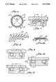
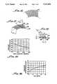
- FIG. 1is a theoretical load vs. a deflection curve illustrating the various parameters of a electromagnetic shielding gasket in accordance with the present invention
- FIG. 2is a plan view of an electromagnetic shielding gasket in accordance with the present invention in which coils are interconnected in a manner forming an axially resilient coil gasket with a trailing portion having a back angle along an inside diameter of the gasket and a leading portion having a front angle along an outside diameter of the gasket, the coils being interconnected to produce a clockwise canting of the coils (the coils also may be interconnected to produce a counterclockwise canting, see FIG. 4);
- FIG. 3is a cross-sectional view of the gasket shown in FIG. 2 taken along a line 3--3 and showing the relative position of the back angle and the front angle of the spring;
- FIG. 4is a plan view of an electromagnetic shielding gasket in accordance with the present invention in which the coils are interconnected to define an axially resilient electromagnetic shielding gasket with a trailing portion having a back angle along an outside diameter of the gasket and a leading portion having front angle along an inside diameter of the gasket, the coils being interconnected to produce a counter-clockwise canting of the coils (the coils also may be interconnected to produce a clockwise canting, see FIG. 2);
- FIG. 5is a cross-sectional view of the electromagnetic gasket of FIG. 4 taken along the line 5--5 and showing the relative positions of the front and the back angle;
- FIG. 6is an electromagnetic gasket in accordance with the present invention in which the coils are interconnected to form a radially resilient electromagnetic gasket
- FIG. 7shows an axially resilient electromagnetic gasket disposed in a cone position and having a load turn angle which may vary, but is shown therein at about 45°;
- FIG. 8is a perspective view of the axially resilient electromagnetic gasket of FIG. 7 taken along a load line and showing a load line, or circle, at which a portion of each coil in the electromagnetic gasket has a spacing between coils;
- FIG. 8ashows, in cross section, an alternative embodiment in which the coils may abutt upon preloading or loading thereof
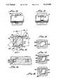
- FIG. 9is an axially resilient electromagnetic gasket shown in a loaded position and in an inverted cone position in which the load turn angle may vary, but is shown therein at about 45°;
- FIG. 10is an axially resilient electromagnetic gasket loaded along the minor axis thereof with a spring load turn angle of about 0 degrees;
- FIGS. 11is an axially resilient electromagnetic gasket loaded along the minor axis thereof, forming a cone, the load turn angle may be from 0 degrees to about 30 degrees. As shown, it is about 15 degrees;
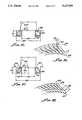
- FIG. 12is a radially resilient electromagnetic gasket disposed in a housing groove
- FIG. 12ais an electromagnetic shielding gasket assembled into housing grooves with a wedge providing means for loading the coils from the outside diameter towards the inside diameter causing the coils to butt towards the inside diameter.
- FIG. 13is a radially resilient electromagnetic gasket disposed in a shaft groove
- FIG. 13ais an electromagnetic shielding gasket assembled in a piston groove with a wedge providing means for loading the coils in a manner causing the coils to deflect at the outside diameter and butt towards the inside diameter.
- FIG. 14is a diagram of an axially resilient electromagnetic gasket showing the loading thereof and showing a wedge for deflecting the gasket along the minor axis thereof, to a butt angle position;
- FIG. 15is an alternative embodiment of the present invention.
- FIGS. 16, 17 and 18are alternative embodiments of the present invention utilizing different shaped wedges and grooves
- FIGS. 19, 20 and 21are alternative embodiments of the present invention showing a wedge in position for compressing radially resilient electromagnetic gasket
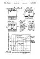
- FIG. 22shows a typical application of an embodiment of the present invention
- FIG. 23shows an alternative embodiment of the present invention in which the groove is defined by mating portions thereby preloading the spring before loading thereof by a third mating member;
- FIG. 24is an axial or radial load deflection curve for a typical axially resilient electromagnetic coil spring in accordance with the present invention.
- FIG. 25is a coil spring in an unloaded or free state
- FIG. 26shows the coil of FIG. 25 in a loaded state with spacing between the individual coils
- FIG. 27is a cross-section of a single individual coil of of the loaded coil of FIG. 26 showing the maximum linear dimension or operation, L, available for electromagnetic wave propagation;
- FIG. 28shows the effect of wire diameter (d) or shield effectiveness for the coils of FIG. 26;
- FIG. 29shows the effect of coil height D to wire diameter (d) on the shield effectiveness for the coils of FIG. 26;
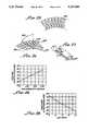
- FIG. 30is a coil spring in an unloaded or free state
- FIG. 31shows the coil of FIG. 30 in a loaded state with the individual coils abutting one another, the wedge causing such butting not shown;
- FIG. 32is a cross-section of adjacent individual coils showing the mzximum linear dimension, L, available for electromagnetic wave propagation;
- FIG. 33shows the effect of wire diameter, D, or shield effectiveness for the coils of FIG. 31.
- FIG. 34shows the effect of coil height to wire diameter (d) on the shield effectiveness for the coil of FIG. 31.
- FIGS. 35 and 36show an axial spring gasket deflected to safety load with spacing between coils at load
- FIGS. 37 and 38show the spring gasket of FIG. 36 loaded with a wedge with coils butting a load circle
- FIG. 39is a plot of Shielding Effectiveness vs. Frequency for plane wave and magnetic fields showing the difference between abutting coils at load and non-autting coils at load for the spring gaskets of FIGS. 35-38.
- a resilient electromagnetic shielding gasket in accordance with the present inventionmay be described, in part, by its load-deflection characteristics.
- a number of load-deflection characteristicsmay be utilized; however, of particular use is a gasket which exerts a generally constant force in response to deflection of the gasket.
- This featureenables the gasket, in accordance with the present invention, to accommodate variations in mating surfaces between which electromagnetic shielding is to be provided. Such variations may be due to surface irregularities, tolerances, or temperature and pressure effects.
- the shielding gasketprovides a stable, long-lived gasket capable of shielding against electromagnetic radiation in a consistent manner over time, despite temperature and pressure effects, and/or continued assembly and disassembly of mating parts.
- an exemplary load-deflection curve 10is shown in FIG. 1.
- a loadis applied to the gasket, it deflects in a generally linear fashion as represented by the line segment 12 until it reaches a minimum load point 14 which represents the point at which, after the initial deflection, the load begins deflection, the load begins to remain relatively constant.
- the load-deflection curvemay be constant or show a slight increase as shown in FIG. 1.
- the gasketis normally loaded for operation within this range, as indicated by the point 20, for a typical gasket in accordance with the present invention, for electromagnetic shielding purposes.
- the gasketalso may provide sealaing between the mating surfaces.
- a gasketas hereinafter identified, in accordance with the present invention, may assume many forms. For example, it may be linear, have any irregular shape, or be interconnected to form a round, elliptical or other continuous shape, as hereinafter discussed.
- an axially resilient electromagnetic shield, or gasket, 30 as shown in FIG. 2may have a plurality of coils 32 interconnected in a manner such that a trailing portion 34, see FIG. 3, is along an inside diameter 36 of the gasket 30 and a leading portion 38 is along an outside diameter 40 of the gasket 30.
- FIG. 2shows the gasket 30 interconnected and wound with a clockwise canting of coils.
- An alternative embodiment(not shown) may be made as described in FIGS. 2 and 3 but having the coils instead canting in a counterclockwise and wound in a counterclockwise direction as shown in FIG. 4.
- the back angle 42provides means for defining the disposition of the trailing portion 34 of each coil with respect to a line 44 normal to the centerline 46 and a front angle 48 provides means for defining the disposition of the leading portion 38 of each coil with respect to a normal line 50.
- the back angle 42additionally determines the working resilient range of the gasket as disclosed in U.S. Pat. Nos. 4,826,144 and 4,915,366. Specific details of the use of the back angle to determine the gasket resilient range are disclosed within these references, which are incorporated herewith by specific reference thereto, and not discussed in detail herein as they disclosed in the cited references.
- FIGS. 4 and 5there is shown an axially resilient circular gasket 60 having a plurality of coils 62 interconnected in a fashion providing a counter-clockwise canting of coils and as shown in FIG. 5, having a back angle 64 defining a trailing portion 66 along an outside diameter 68 and a front angle 70 defining a leading portion 72 along the inside diameter 74 of the gasket 60.
- FIG. 4shows the gasket 60 interconnected and wound with a counterclockwise canting of coils.
- An alternative embodiment(not shown) may be made as described in FIGS. 4 and 5 but having the direction of canting in a clockwise direction (see FIG. 2).
- the direction of windingmay be reversed.
- an electromagnetic gasket 80may include a plurality of conductive coils 82 canted along a centerline 84 thereof and interconnected in a manner forming a circular radially resistant gasket. Loading of the gasket 80 occurs in a radial manner as indicated by the load arrows 86.
- FIG. 7there is shown in a diagrammatic cross-sectional manner the axially resilient gasket 30 disposed in a groove 90, which provides means for preloading the plurality of coils 32 in a manner causing coil spacing along the circumference of the inside diameter of the spring as loaded to be less along the inside diameter 98 and such spacing to increase progressively at seal-load 92 of each coil 32 and increase further towards the O.D. of the spring.
- the coil spacing along these seal-load portions 92is selected to limit the passage of electromagnetic energy with a wave length greater than a selected value.
- FIG. 8a diagrammatic perspective view taken along a load circle 96 is shown in FIG. 8.
- the load line/circle 96being collectively defined by the seal-load portions 92 of the coils 32.
- FIG. 8shows the gasket 30 in a loaded position with spacing between coils.
- load sealing points 100are coincident with the load circle 96 when the gasket 30 is disposed in the groove 90 at a load turn angle ⁇ which may be from about 1 degrees to 90 degrees, and preferably 45 degrees.
- the gasket 30is shown in a "cone" configuration and as such develops a small load circle which is disposed proximate the gasket inside diameter 36. (See FIG. 2). After assembly of the gasket 30 into the groove 90, it is generally loaded by a flange 110.
- the groove width 112may be either smaller, equal to or larger than the coil height 114. However, it is preferable that the groove width is greater than the coil height as there is less possibility of spring damage upon loading the spring.
- the gasket 30will have a force-deflection characteristic which generally provides a force versus deflection where the force remains generally constant within the working deflection.
- the assembly turn anglesee FIG. 35
- the spring back angleis at the O.D. which causes the force versus deflection curve to rise rapidly above the constant force and this is an indication that the fatiguing of the gasket may occur.
- FIG. 8ashows a cross-section of the gasket 30 which is loaded with coils 32 abutting which shows a minimum area 102 subtended by the surface of adjoining and abutting coils 32 and a load surface 106.
- a conductive wire 108may be disposed between abutting coils 32 in the area 102 for providing insert means to further limit the passage of electromagnetic therepast, or between the abutting coils 32.
- the conductive insert wire 108may have a circular or V shape cross-section in order to more fully occupy the area 102.
- FIG. 9there is shown an alternative embodiment of the present invention in which an axially resilient gasket 120 is shown in a loading position having a load turn angle which may be between 1 degree and 90 degrees, a preferred load turn angle of 45 degrees being shown.
- the gasketassumes an inverted cone shape and the position of the gasket is similar to the axial cone gasket except that upon assembly the gasket into the cavity, it is in an inverted position which is 180 degrees from the cone position.
- the load circle 122is substantially larger than in the axial cone type spring 30 and that allows greater open spacing between the coils occurring at the load circle 122.
- the force vs. deflection characteristics of this type gasketis as shown in FIG. 1, with an initial higher peak above the constant force when the assembly turn angle ⁇ (see FIG. 35) is greater than 70 degrees and the spring back angle is at the O.D. instead of the I.D.
- FIG. 10Shown in FIG. 10 is an axially resilient gasket 140 as shown loaded along a minor axis 142 thereof.
- the groove width G Wis greater than the coil width C W .
- FIG. 11Another positioning of an axially resilient cone gasket 150 is shown in FIG. 11 in which the axial turn angle is between 0 and about 30 degrees and the load along the load circle 152 is along a minor axis 154 of the gasket 150. More detailed description of a coil preloading and loading within the groove will be hereinafter discussed in greater detail.
- FIGS. 12 and 13Shown in FIGS. 12 and 13 are radial resilient gaskets 160, 162, respectively, in accordance with the present invention, shown within grooves 164 and 166, formed in a housing 168 and a shaft 170, respectively.
- FIG. 12ashows the spring 160 disposed in a housing 168a having two portions 168b, 168c with a wedge 168d for defining a cavity 169 between the housing 168a and shaft 170.
- the wedge 168dloads the cavity 160 in a manner causing the spring 160 to progressively abut at the inside diameter.
- FIG. 13ashows the spring 162 disposed in a piston 170a having a wedge portion 170b defining a cavity 171 which loads the spring in a manner shown in FIG. 31 causing the spring 162 to deflect and progressively abut from the inside diameter.
- FIG. 14shows an enlarged view of an axially resilient electromagnetic shielding gasket 172 within a groove, or cavity, 174 and further including a wedge 176 which may be suspended in the groove 174 and biased by the plurality of coils 178 against an opposing loading surface 180 in order to cause coil spacing along the circumference of adjoining coils to be less along the I.D. of the spring gasket at 206 when in a loaded position than along other coiled portions 184 184 along the circumference thereof.
- the spacing between coils when loadedwill be slightly greater than at circumference 206 and such spacing between coils progressively increases from the I.D. of the spring circumference when loaded.
- An important feature of the wedge 176is the enablement of the coils 178 to abut without causing fatigue, or permanet set thereof which deflects the coils 178 from a coil height 194 to 180 and also causes the rotation of coils 178 within the groove 174 and thereby increases the shielding effectiveness of the gasket 172.
- the wedgeprevents fatigue by rotation of the coils 178 in a manner increasing the assembly turn angle ⁇ 196 to load turn angle ⁇ 202 thereof as herein described.
- the coilcan be made to abut along the load circle, yet be in a spaced-apart relationship along other portions 184 of the circumference.
- Wedge 176is shown as a separate part; however, it can also be made as an integral part of the loading surface 180.
- the separate wedgehas the significant advantage that it can accommodate itself to the cavity 174 and may provide substantially better shielding effectiveness than a built-in wedge, shown in FIGS. 12a and 13a, in cases where the wedge 176 is sufficiently flexible to be able to be deflected by the spring gasket 172.
- the built-in wedgehas the significant advantage that the wedge and the loading means are in one unit, thus making it easier to fabricate, assemble and load.
- the groove width G Wmay be equal to the groove depth G D and, for example, these dimensions may be in the order of 0.15 inches.
- the gasket 172may have a coil height 194 at assembly turn angle 196 of approximately 45 degrees and a coil width 198 of approximately 0.168 inches and form from wire having approximately 0.16 inch diameter.
- FIG. 15An alternative embodiment of the present invention is shown in FIG. 15 in which a gasket 220 is disposed in a groove 222 and biased by a wedge 224 having a greater width than height.
- Wedge 224can also be made as an integral part of the load surface as hereinabove described. Utilizing wedges 224 of different configurations, as for example shown in FIG. 15, the rate of butting of the coil 220 from the inside diameter towards the outside diameter as hereinabove described in connection with the gasket 172 may be varied. This enables load-deflection characteristics to be achieved with various groove widths G W and groove depths G D .
- FIGS. 16, 17 and 18show an axially resilient gasket 240 in combination with grooves 242, 244 and 246 and wedges 248, 250, 252, respectively.
- the wedges 248, 250, 252may be an integral part of the loading surface.
- These alternative embodimentsshow the wedge 248 having a leg portion, 254 which can be used to modify the groove width.
- the groove 244may have a tapered portion 256 for additionally compressing the spring 240 along the minor axis 258 thereof.
- FIG. 18shows in FIG. 18 wherein the wedge 250 has a V shape and cooperates with wedge 252 for biasing the spring 240.
- FIGS. 19, 20 and 21show a radially resilient gasket 270 as it may be disposed in grooves 272, 274 and 276, respectively, along with loading by wedges 278, 280, 282.
- the gasket 270may be housing 290 mounted or piston 292 mounted.
- the groove 272, 274, 276may be disposed in a single housing or a piston, not shown, or alternatively, may be formed in conjunction with a mating member 300, 302, 304, respectively.
- a wedge shaped gasket 282may be utilized when a beveled edge 306 incorporated into the mating member 304.
- FIG. 22shows a gasket 310 disposed in a groove 312 formed by mating portions 314, 316 which are held in position for biasing by the gasket 110 and by a clip member 318.
- FIG. 23shows a built-in wedge 330 for biasing the gasket 332 within a groove 334 formed by right and left hand members 336, 338, with the gasket 332 being loaded by a flange 340.
- FIG. 24shows a specific load-deflection curve for a gasket made in accordance with the present invention having the dimensions set forth in the description of FIG. 14.
- the springis made from wire having a circular cross-section with a diameter of 0.022 inches, a coil height of about 0.16 inches, a back angle of between about 13 and about 15 degrees, a front angle between 29 and 31 degrees and coil spacing of between about 0.19 inches and 0.17 inches.
- FIGS. 25-26showing in diagrammatic form a plurality of coils in an unloaded state and loaded between surfaces along with a load circle.
- FIG. 27is an enlarged view of one coil showing the aperture, L, extending from a point 360 of contact on load surface 352 at the O.D. of the coil 350 to the top 362 of the coil 350 bearing on the load surface 354.
- the aperture, Lcan be made smaller and hence increase shield effectiveness for a given frequency by increasing coil wire diameter, d.
- Coil height Dalso affects the approximate size. It should be apparent that for a fixed wire diameter, d, an increase in coil height, D, decreases shield effectiveness for a given frequency. This is shown in FIG. 29. Consequently, for gaskets in accordance with the present invention in which the individual coils do not abut, the greater the wire diameter, d, and the smaller the coil height 350, D, the greater the shield effectiveness.
- FIG. 30is an enlarged view of the maximum linear dimension, or aperture, L, available for electromagnetic propagation.
- the aperture, L, for abutting coilsis significantly less than the aperture, L, in the case of spaced-apart coils shown in FIGS. 26-27.
- a gasket with coils abuttinghas up to four times the shielding effectiveness than coils not abutting.
- shielding effectivenessis affected by the aperture length, L, which is determined, in part, by whether the coils 32 (FIG. 8) are spaced apart at load, or abut, as do coils (FIG. 26).
- FIG. 39A calculated comparison of the shielding efficiency of a spring 400 having the specification set forth in Table 1 with coils not abutting, see FIGS. 35-36, and coils abutting, see FIGS. 37-38 is shown in FIG. 39.
- the spring 400is shown in a groove 402 having a width CW and a height GH with the coils 404 having an assembled turn angle ⁇ AP of about 70° and a load turn angle ⁇ LP of about 45°, LC denotes the load circle with the spring 400 axially loaded.
- the spacing 410 between coilsis more clearly shown in FIG. 36 along with the groove inside diameter 412, outside diameter 414 and load circle, LC.
- FIG. 37shows the spring 400 with the coils 404 loaded to a butting position by a wedge 420.
- the groove 422has an outside height, GWO, greater than an inside height, GWI.
- the coils 404have an assembled turn angle ⁇ AP of about 70° and a load turn angle ⁇ LP of about 55°.
- the coilsabut from the groove inside diameter 412 to the load circle LC as indicated also by an arrow 430.
- the average aperture for coils 404 abutting and open for various groove l.D., 412is shown in Table 2.
- the difference in shielding effectivenessis also 13.3, and, therefore, the increase in shielding effectiveness when the coils are butting versus when the coils are open is, again, 6.6 times greater.
Landscapes
- Engineering & Computer Science (AREA)
- General Engineering & Computer Science (AREA)
- Mechanical Engineering (AREA)
- Microelectronics & Electronic Packaging (AREA)
- Gasket Seals (AREA)
- Shielding Devices Or Components To Electric Or Magnetic Fields (AREA)
Abstract
Description
TABLE 1 ______________________________________ SPRING PARAMETERS ______________________________________ Wire Diameter 0.03 inch Coil Height 0.025 inch Coil Width 0.023inch Back Angle 12° Spacing Between 0.0035 inch Coils Spring I.D. 0.063 inch Approx. # of 35 Coils ______________________________________
TABLE 2 ______________________________________ COILS Butting Open GROOVE Avg. Avg. Avg. Avg. I.D. Aperture # Aperture # (Inches) (inches) Coils (inches) Coils ______________________________________ 0.063 0.0056 35.5 0.0257 35.5 0.125 0.0065 61.0 0.0264 61.0 0.250 0.0071 111.5 0.0268 111.5 0.500 0.0074 213.0 0.0271 213.0 ______________________________________
Claims (17)
Priority Applications (3)
| Application Number | Priority Date | Filing Date | Title |
|---|---|---|---|
| US07/645,197US5117066A (en) | 1988-04-25 | 1991-01-24 | Retaining and locking electromagnetic gasket |
| EP19920101041EP0496389A3 (en) | 1991-01-24 | 1992-01-23 | Retaining and locking electromagnetic gasket |
| JP4011388AJPH04334098A (en) | 1991-01-24 | 1992-01-24 | Electromagnetic shield spring gasket assembly |
Applications Claiming Priority (4)
| Application Number | Priority Date | Filing Date | Title |
|---|---|---|---|
| US07/186,017US4830344A (en) | 1988-04-25 | 1988-04-25 | Canted-coil spring with turn angle and seal |
| US07/444,287US5072070A (en) | 1989-12-01 | 1989-12-01 | Device for sealing electromagnetic waves |
| US07/568,909US5079388A (en) | 1989-12-01 | 1990-08-17 | Gasket for sealing electromagnetic waves |
| US07/645,197US5117066A (en) | 1988-04-25 | 1991-01-24 | Retaining and locking electromagnetic gasket |
Related Parent Applications (1)
| Application Number | Title | Priority Date | Filing Date |
|---|---|---|---|
| US07/568,909Continuation-In-PartUS5079388A (en) | 1988-04-25 | 1990-08-17 | Gasket for sealing electromagnetic waves |
Publications (1)
| Publication Number | Publication Date |
|---|---|
| US5117066Atrue US5117066A (en) | 1992-05-26 |
Family
ID=24588029
Family Applications (1)
| Application Number | Title | Priority Date | Filing Date |
|---|---|---|---|
| US07/645,197Expired - LifetimeUS5117066A (en) | 1988-04-25 | 1991-01-24 | Retaining and locking electromagnetic gasket |
Country Status (3)
| Country | Link |
|---|---|
| US (1) | US5117066A (en) |
| EP (1) | EP0496389A3 (en) |
| JP (1) | JPH04334098A (en) |
Cited By (76)
| Publication number | Priority date | Publication date | Assignee | Title |
|---|---|---|---|---|
| US5411348A (en)* | 1993-10-26 | 1995-05-02 | Bal Seal Engineering Company, Inc. | Spring mechanism to connect, lock and unlock, members |
| US5474309A (en)* | 1993-06-11 | 1995-12-12 | Bal Seal Engineering Company, Inc. | Gasket assembly for sealing electromagnetic waves |
| DE4439671A1 (en)* | 1994-11-07 | 1996-05-09 | Abb Management Ag | Contact spring for heavy current contact device |
| US5545842A (en)* | 1993-10-26 | 1996-08-13 | Bal Seal Engineering Company, Inc. | Radially mounted spring to connect, lock and unlock, and for snap-on fastening, and for mechanical, electromagnetic shielding, electrical conductivity, and thermal dissipation with environmental sealing |
| US5560278A (en)* | 1994-10-11 | 1996-10-01 | Caterpillar Inc. | Hydraulic cylinder with an electrical contacting and sealing ring |
| EP0890758A2 (en) | 1997-07-07 | 1999-01-13 | Bal Seal Engineering Company, Inc. | Radial and axial springs with coils canting along the major axis |
| US5876436A (en)* | 1994-10-21 | 1999-03-02 | St. Jude Medical, Inc. | Rotatable cuff assembly for a heart valve prosthesis |
| US6325391B1 (en)* | 1998-11-12 | 2001-12-04 | Rosemount Inc. | PTFE window seal with EMI shielding |
| US6358278B1 (en) | 1999-09-24 | 2002-03-19 | St. Jude Medical, Inc. | Heart valve prosthesis with rotatable cuff |
| US6433271B1 (en)* | 1995-01-26 | 2002-08-13 | Abb Ab | Method for arranging a busbar system and a busbar system |
| FR2820672A1 (en)* | 2001-02-09 | 2002-08-16 | Hilti Ag | HOLDER PISTON |
| US20030158570A1 (en)* | 2000-04-13 | 2003-08-21 | Paolo Ferrazzi | Endoventicular device for the treatment and correction of cardiomyopathies |
| US20030204262A1 (en)* | 2002-04-30 | 2003-10-30 | Ferguson Joe William | Quick disconnect orthopaedic trials |
| US20040193268A1 (en)* | 2003-03-31 | 2004-09-30 | Hazebrouck Stephen A. | Intercalary prosthesis, kit and method |
| US20040193267A1 (en)* | 2003-03-31 | 2004-09-30 | Jones Michael C. | Intercalary implant |
| US20050001384A1 (en)* | 2003-05-03 | 2005-01-06 | Reinhard Feinmechanik Gmbh | Shaft sealing module for sealing vacuum chambers |
| US20050107794A1 (en)* | 2003-03-31 | 2005-05-19 | Hazebrouck Stephen A. | Orthopaedic spacer |
| WO2004074669A3 (en)* | 2003-02-18 | 2005-06-09 | Bal Seal Eng Co Inc | Spring holding connectors |
| US20060071848A1 (en)* | 2004-10-01 | 2006-04-06 | Saab Rosemount Tank Radar Ab | Microwave sealing for radar level gauges |
| US20070281024A1 (en)* | 2005-02-03 | 2007-12-06 | Alza Corporation | Two-Piece, Internal-Channel Osmotic Delivery System Flow Modulator |
| US20080091176A1 (en)* | 2006-08-09 | 2008-04-17 | Alessi Thomas R | Osmotic delivery systems and piston assemblies for use therein |
| US20090051121A1 (en)* | 2007-08-20 | 2009-02-26 | Interson Corporation | Seal for a rotating shaft |
| US20090160139A1 (en)* | 2007-12-21 | 2009-06-25 | Balsells Pete J | Locking mechanism with quick disassembly means |
| US20090322036A1 (en)* | 2008-06-27 | 2009-12-31 | Halling Horace P | Gas turbine nozzle seals for 2000 degree f gas containment |
| US20100224400A1 (en)* | 2009-03-06 | 2010-09-09 | Saint-Gobain Performance Plastics Corporation | Overlap helical conductive spring |
| US7810816B1 (en) | 2005-12-13 | 2010-10-12 | Horace P. Halling | Seal |
| US20110068543A1 (en)* | 2004-02-25 | 2011-03-24 | John Wentworth Bucknell | Seals for Hydraulic Assemblies |
| US20110088940A1 (en)* | 2009-10-16 | 2011-04-21 | Emprimus, Inc. | Modular Electromagnetically Shielded Enclosure |
| US20120301248A1 (en)* | 2011-05-25 | 2012-11-29 | Nuvasive, Inc. | System and Method for Fastening Objects Together |
| US8428724B2 (en) | 2011-03-11 | 2013-04-23 | Greatbatch Ltd. | Low insertion force electrical connector for implantable medical devices |
| US8547710B2 (en) | 2009-10-16 | 2013-10-01 | Emprimus, Llc | Electromagnetically shielded power module |
| US8599576B2 (en) | 2010-10-29 | 2013-12-03 | Emprimus, Llc | Electromagnetically-protected electronic equipment |
| US8643772B2 (en) | 2010-11-05 | 2014-02-04 | Emprimus, Llc | Electromagnetically shielded video camera and shielded enclosure for image capture devices |
| EP2387113A3 (en)* | 2010-05-13 | 2014-03-26 | Bal Seal Engineering Co. | Multi-piece canted coil spring socket |
| US8754980B2 (en) | 2010-11-05 | 2014-06-17 | Emprimus, Llc | Electromagnetically shielded camera and shielded enclosure for image capture devices |
| US8760859B2 (en) | 2010-05-03 | 2014-06-24 | Emprimus, Llc | Electromagnetically-shielded portable storage device |
| US20150001804A1 (en)* | 2013-06-27 | 2015-01-01 | Aktiebolaget Skf | Fluid seal assembly with wear ring |
| US8933393B2 (en) | 2011-04-06 | 2015-01-13 | Emprimus, Llc | Electromagnetically-shielded optical system having a waveguide beyond cutoff extending through a shielding surface of an electromagnetically shielding enclosure |
| US9093755B2 (en) | 2010-12-20 | 2015-07-28 | Emprimus, Llc | Lower power localized distributed radio frequency transmitter |
| US20150240951A1 (en)* | 2012-09-07 | 2015-08-27 | Siemens Aktiengesellschaft | Arrangement with a gas seal |
| US9124141B2 (en) | 2009-06-26 | 2015-09-01 | Mitsubishi Heavy Industries, Ltd. | Wireless power transmission system |
| US9420219B2 (en) | 2010-12-20 | 2016-08-16 | Emprimus, Llc | Integrated security video and electromagnetic pulse detector |
| US9526763B2 (en) | 2005-02-03 | 2016-12-27 | Intarcia Therapeutics Inc. | Solvent/polymer solutions as suspension vehicles |
| US9572889B2 (en) | 2008-02-13 | 2017-02-21 | Intarcia Therapeutics, Inc. | Devices, formulations, and methods for delivery of multiple beneficial agents |
| US9642290B2 (en) | 2013-03-14 | 2017-05-02 | Emprimus, Llc | Electromagnetically protected electronic enclosure |
| US9682127B2 (en) | 2005-02-03 | 2017-06-20 | Intarcia Therapeutics, Inc. | Osmotic delivery device comprising an insulinotropic peptide and uses thereof |
| US9724293B2 (en) | 2003-11-17 | 2017-08-08 | Intarcia Therapeutics, Inc. | Methods of manufacturing viscous liquid pharmaceutical formulations |
| US9889085B1 (en) | 2014-09-30 | 2018-02-13 | Intarcia Therapeutics, Inc. | Therapeutic methods for the treatment of diabetes and related conditions for patients with high baseline HbA1c |
| US9927034B2 (en)* | 2015-08-25 | 2018-03-27 | Mueller International, Llc | Valve seat stiffener |
| US20180119857A1 (en)* | 2016-10-31 | 2018-05-03 | Bal Seal Engineering, Inc. | Axial and radial floating seals |
| US10117366B2 (en) | 2015-12-14 | 2018-10-30 | Bal Seal Engineering, Inc. | Spring energized seals and related methods |
| US10125872B2 (en) | 2011-08-18 | 2018-11-13 | Bal Seal Engineering, Inc. | Reciprocating seal for high pulsating pressure |
| US10151368B2 (en)* | 2014-05-02 | 2018-12-11 | Bal Seal Engineering, Inc. | Nested canted coil springs, applications thereof, and related methods |
| USD835783S1 (en) | 2016-06-02 | 2018-12-11 | Intarcia Therapeutics, Inc. | Implant placement guide |
| US10159714B2 (en) | 2011-02-16 | 2018-12-25 | Intarcia Therapeutics, Inc. | Compositions, devices and methods of use thereof for the treatment of cancers |
| US10231923B2 (en) | 2009-09-28 | 2019-03-19 | Intarcia Therapeutics, Inc. | Rapid establishment and/or termination of substantial steady-state drug delivery |
| US10288203B2 (en) | 2014-03-26 | 2019-05-14 | Nelson Products, Inc. | Latching connector with radial grooves |
| USD860451S1 (en) | 2016-06-02 | 2019-09-17 | Intarcia Therapeutics, Inc. | Implant removal tool |
| US10501517B2 (en) | 2016-05-16 | 2019-12-10 | Intarcia Therapeutics, Inc. | Glucagon-receptor selective polypeptides and methods of use thereof |
| US10520091B2 (en) | 2009-07-08 | 2019-12-31 | Bal Seal Engineering, Inc. | Double direction seal with locking |
| US10520092B2 (en) | 2016-10-24 | 2019-12-31 | Bal Seal Engineering, Inc. | Seal assemblies for extreme temperatures and related methods |
| US10598241B2 (en) | 2014-02-26 | 2020-03-24 | Bal Seal Engineering, Inc. | Multi deflection canted coil springs and related methods |
| US10835580B2 (en) | 2017-01-03 | 2020-11-17 | Intarcia Therapeutics, Inc. | Methods comprising continuous administration of a GLP-1 receptor agonist and co-administration of a drug |
| US10900531B2 (en) | 2017-08-30 | 2021-01-26 | Bal Seal Engineering, Llc | Spring wire ends to faciliate welding |
| US10925639B2 (en) | 2015-06-03 | 2021-02-23 | Intarcia Therapeutics, Inc. | Implant placement and removal systems |
| USD933219S1 (en) | 2018-07-13 | 2021-10-12 | Intarcia Therapeutics, Inc. | Implant removal tool and assembly |
| US20210364089A1 (en)* | 2018-05-08 | 2021-11-25 | Bal Seal Engineering, Llc | Seal assemblies and related methods |
| US11246913B2 (en) | 2005-02-03 | 2022-02-15 | Intarcia Therapeutics, Inc. | Suspension formulation comprising an insulinotropic peptide |
| US11353079B2 (en) | 2017-10-05 | 2022-06-07 | Bal Seal Engineering, Llc | Spring assemblies, applications of spring assemblies, and related methods |
| US11480250B2 (en) | 2017-03-16 | 2022-10-25 | Bal Seal Engineering, Llc | V-springs and seals with v-springs |
| US11536373B2 (en) | 2016-03-07 | 2022-12-27 | Bal Seal Engineering, Llc | Seal assemblies and related methods |
| US11746906B1 (en) | 2022-11-01 | 2023-09-05 | Bal Seal Engineering, Llc | Lip seals and related methods |
| US11940049B1 (en) | 2022-11-01 | 2024-03-26 | Bal Seal Engineering, Llc | Lip seals and related methods |
| DE102023101561A1 (en) | 2023-01-23 | 2024-07-25 | Harting Electric Stiftung & Co. Kg | Contact element for connectors of energy storage devices |
| US12092160B2 (en) | 2021-09-23 | 2024-09-17 | Bal Seal Engineering Llc | Integrated seal and bearing assembly and related methods |
| US12247663B2 (en) | 2022-11-01 | 2025-03-11 | Bal Seal Engineering, Llc | Lip seals and related methods |
Families Citing this family (2)
| Publication number | Priority date | Publication date | Assignee | Title |
|---|---|---|---|---|
| US9357684B2 (en) | 2013-09-24 | 2016-05-31 | Bal Seal Engineering, Inc. | Spring assemblies with spring energized seal members and related methods |
| CN105127673B (en)* | 2014-06-06 | 2019-06-04 | 舍弗勒技术股份两合公司 | Pre-tightening spring of clutch control mechanism, forming method and clutch control mechanism |
Citations (3)
| Publication number | Priority date | Publication date | Assignee | Title |
|---|---|---|---|---|
| GB774419A (en)* | 1954-09-20 | 1957-05-08 | Marconi Instruments Ltd | Improvements in or relating to screening arrangements for radio and other high frequency apparatus |
| US4655462A (en)* | 1985-01-07 | 1987-04-07 | Peter J. Balsells | Canted coiled spring and seal |
| US4934666A (en)* | 1988-04-25 | 1990-06-19 | Peter J. Balsells | Coiled spring electromagnetic shielding gasket |
Family Cites Families (6)
| Publication number | Priority date | Publication date | Assignee | Title |
|---|---|---|---|---|
| US3835443A (en)* | 1973-04-25 | 1974-09-10 | Itt | Electrical connector shield |
| US4033654A (en)* | 1976-07-29 | 1977-07-05 | Automation Industries, Inc. | Electrical connector |
| GB2057789B (en)* | 1979-08-31 | 1983-09-28 | Bendix Corp | Two part connector having electromagnetic interference protection |
| US4529257A (en)* | 1983-02-22 | 1985-07-16 | International-Telephone & Telegraph Corp. | Combined electrical shield and environmental seal for electrical connector |
| US5079388A (en)* | 1989-12-01 | 1992-01-07 | Peter J. Balsells | Gasket for sealing electromagnetic waves |
| US5072070A (en)* | 1989-12-01 | 1991-12-10 | Peter J. Balsells | Device for sealing electromagnetic waves |
- 1991
- 1991-01-24USUS07/645,197patent/US5117066A/ennot_activeExpired - Lifetime
- 1992
- 1992-01-23EPEP19920101041patent/EP0496389A3/ennot_activeWithdrawn
- 1992-01-24JPJP4011388Apatent/JPH04334098A/enactivePending
Patent Citations (3)
| Publication number | Priority date | Publication date | Assignee | Title |
|---|---|---|---|---|
| GB774419A (en)* | 1954-09-20 | 1957-05-08 | Marconi Instruments Ltd | Improvements in or relating to screening arrangements for radio and other high frequency apparatus |
| US4655462A (en)* | 1985-01-07 | 1987-04-07 | Peter J. Balsells | Canted coiled spring and seal |
| US4934666A (en)* | 1988-04-25 | 1990-06-19 | Peter J. Balsells | Coiled spring electromagnetic shielding gasket |
Cited By (118)
| Publication number | Priority date | Publication date | Assignee | Title |
|---|---|---|---|---|
| US5474309A (en)* | 1993-06-11 | 1995-12-12 | Bal Seal Engineering Company, Inc. | Gasket assembly for sealing electromagnetic waves |
| US5411348A (en)* | 1993-10-26 | 1995-05-02 | Bal Seal Engineering Company, Inc. | Spring mechanism to connect, lock and unlock, members |
| US5545842A (en)* | 1993-10-26 | 1996-08-13 | Bal Seal Engineering Company, Inc. | Radially mounted spring to connect, lock and unlock, and for snap-on fastening, and for mechanical, electromagnetic shielding, electrical conductivity, and thermal dissipation with environmental sealing |
| US5560278A (en)* | 1994-10-11 | 1996-10-01 | Caterpillar Inc. | Hydraulic cylinder with an electrical contacting and sealing ring |
| US5876436A (en)* | 1994-10-21 | 1999-03-02 | St. Jude Medical, Inc. | Rotatable cuff assembly for a heart valve prosthesis |
| DE4439671A1 (en)* | 1994-11-07 | 1996-05-09 | Abb Management Ag | Contact spring for heavy current contact device |
| US6433271B1 (en)* | 1995-01-26 | 2002-08-13 | Abb Ab | Method for arranging a busbar system and a busbar system |
| EP0890758A2 (en) | 1997-07-07 | 1999-01-13 | Bal Seal Engineering Company, Inc. | Radial and axial springs with coils canting along the major axis |
| US6325391B1 (en)* | 1998-11-12 | 2001-12-04 | Rosemount Inc. | PTFE window seal with EMI shielding |
| US6358278B1 (en) | 1999-09-24 | 2002-03-19 | St. Jude Medical, Inc. | Heart valve prosthesis with rotatable cuff |
| US20030158570A1 (en)* | 2000-04-13 | 2003-08-21 | Paolo Ferrazzi | Endoventicular device for the treatment and correction of cardiomyopathies |
| US7731649B2 (en)* | 2000-04-13 | 2010-06-08 | Cube S.R.L. | Endoventicular device for the treatment and correction of cardiomyopathies |
| FR2820672A1 (en)* | 2001-02-09 | 2002-08-16 | Hilti Ag | HOLDER PISTON |
| US20030204262A1 (en)* | 2002-04-30 | 2003-10-30 | Ferguson Joe William | Quick disconnect orthopaedic trials |
| WO2004074669A3 (en)* | 2003-02-18 | 2005-06-09 | Bal Seal Eng Co Inc | Spring holding connectors |
| US7125423B2 (en) | 2003-03-31 | 2006-10-24 | Depuy Products, Inc. | Intercalary prosthesis, kit and method |
| US20050107794A1 (en)* | 2003-03-31 | 2005-05-19 | Hazebrouck Stephen A. | Orthopaedic spacer |
| US7141067B2 (en) | 2003-03-31 | 2006-11-28 | Depuy Products, Inc. | Intercalary implant |
| US7198642B2 (en) | 2003-03-31 | 2007-04-03 | Depuy Products, Inc. | Orthopaedic spacer |
| US20040193268A1 (en)* | 2003-03-31 | 2004-09-30 | Hazebrouck Stephen A. | Intercalary prosthesis, kit and method |
| US20040193267A1 (en)* | 2003-03-31 | 2004-09-30 | Jones Michael C. | Intercalary implant |
| US20050001384A1 (en)* | 2003-05-03 | 2005-01-06 | Reinhard Feinmechanik Gmbh | Shaft sealing module for sealing vacuum chambers |
| US7090223B2 (en)* | 2003-05-03 | 2006-08-15 | Reinhard Feinmechanik Gmbh | Shaft sealing module for sealing vacuum chambers |
| US9724293B2 (en) | 2003-11-17 | 2017-08-08 | Intarcia Therapeutics, Inc. | Methods of manufacturing viscous liquid pharmaceutical formulations |
| US20110068543A1 (en)* | 2004-02-25 | 2011-03-24 | John Wentworth Bucknell | Seals for Hydraulic Assemblies |
| US20060071848A1 (en)* | 2004-10-01 | 2006-04-06 | Saab Rosemount Tank Radar Ab | Microwave sealing for radar level gauges |
| US7239267B2 (en)* | 2004-10-01 | 2007-07-03 | Rosemount Tank Radar Ab | Microwave sealing for radar level gauges |
| US20070252752A1 (en)* | 2004-10-01 | 2007-11-01 | Olov Edvardsson | Microwave sealing for radar level gauging |
| US10363287B2 (en) | 2005-02-03 | 2019-07-30 | Intarcia Therapeutics, Inc. | Method of manufacturing an osmotic delivery device |
| US9539200B2 (en) | 2005-02-03 | 2017-01-10 | Intarcia Therapeutics Inc. | Two-piece, internal-channel osmotic delivery system flow modulator |
| US9526763B2 (en) | 2005-02-03 | 2016-12-27 | Intarcia Therapeutics Inc. | Solvent/polymer solutions as suspension vehicles |
| US9682127B2 (en) | 2005-02-03 | 2017-06-20 | Intarcia Therapeutics, Inc. | Osmotic delivery device comprising an insulinotropic peptide and uses thereof |
| US8992962B2 (en) | 2005-02-03 | 2015-03-31 | Intarcia Therapeutics Inc. | Two-piece, internal-channel osmotic delivery system flow modulator |
| US20070281024A1 (en)* | 2005-02-03 | 2007-12-06 | Alza Corporation | Two-Piece, Internal-Channel Osmotic Delivery System Flow Modulator |
| US8470353B2 (en) | 2005-02-03 | 2013-06-25 | Intarcia Therapeutics, Inc. | Two-piece, internal-channel osmotic delivery system flow modulator |
| US11246913B2 (en) | 2005-02-03 | 2022-02-15 | Intarcia Therapeutics, Inc. | Suspension formulation comprising an insulinotropic peptide |
| US8367095B2 (en) | 2005-02-03 | 2013-02-05 | Intarcia Therapeutics, Inc. | Two-piece, internal-channel osmotic delivery system flow modulator |
| US8052996B2 (en) | 2005-02-03 | 2011-11-08 | Intarcia Therapeutics, Inc. | Two-piece, internal-channel osmotic delivery system flow modulator |
| US8273365B2 (en) | 2005-02-03 | 2012-09-25 | Intarcia Therapeutics, Inc. | Two-piece, internal-channel osmotic delivery system flow modulator |
| US8158150B2 (en) | 2005-02-03 | 2012-04-17 | Intarcia Therapeutics, Inc. | Two-piece, internal-channel osmotic delivery system flow modulator |
| US20110057394A1 (en)* | 2005-12-13 | 2011-03-10 | Halling Horace P | Seal |
| US7810816B1 (en) | 2005-12-13 | 2010-10-12 | Horace P. Halling | Seal |
| US8801700B2 (en) | 2006-08-09 | 2014-08-12 | Intarcia Therapeutics, Inc. | Osmotic delivery systems and piston assemblies for use therein |
| US7682356B2 (en) | 2006-08-09 | 2010-03-23 | Intarcia Therapeutics, Inc. | Osmotic delivery systems and piston assemblies for use therein |
| US20080091176A1 (en)* | 2006-08-09 | 2008-04-17 | Alessi Thomas R | Osmotic delivery systems and piston assemblies for use therein |
| US20110166554A1 (en)* | 2006-08-09 | 2011-07-07 | Intarcia Therapeutics, Inc. | Osmotic delivery systems and piston assemblies for use therein |
| US10527170B2 (en) | 2006-08-09 | 2020-01-07 | Intarcia Therapeutics, Inc. | Osmotic delivery systems and piston assemblies for use therein |
| US20100185184A1 (en)* | 2006-08-09 | 2010-07-22 | Intarcia Therapeutics, Inc. | Osmotic delivery systems and piston assemblies for use therein |
| US7879028B2 (en) | 2006-08-09 | 2011-02-01 | Intarcia Therapeutics, Inc. | Osmotic delivery systems and piston assemblies for use therein |
| US20090051121A1 (en)* | 2007-08-20 | 2009-02-26 | Interson Corporation | Seal for a rotating shaft |
| US8114024B2 (en) | 2007-08-20 | 2012-02-14 | Interson Corporation | Seal for a rotating shaft |
| US20090160139A1 (en)* | 2007-12-21 | 2009-06-25 | Balsells Pete J | Locking mechanism with quick disassembly means |
| US8308167B2 (en)* | 2007-12-21 | 2012-11-13 | Bal Seal Engineering, Inc. | Locking mechanism with quick disassembly means |
| US9572889B2 (en) | 2008-02-13 | 2017-02-21 | Intarcia Therapeutics, Inc. | Devices, formulations, and methods for delivery of multiple beneficial agents |
| US10441528B2 (en) | 2008-02-13 | 2019-10-15 | Intarcia Therapeutics, Inc. | Devices, formulations, and methods for delivery of multiple beneficial agents |
| US20090322036A1 (en)* | 2008-06-27 | 2009-12-31 | Halling Horace P | Gas turbine nozzle seals for 2000 degree f gas containment |
| US8104772B2 (en) | 2008-06-27 | 2012-01-31 | Seal Science & Technology, Llc | Gas turbine nozzle seals for 2000° F. gas containment |
| US20100224400A1 (en)* | 2009-03-06 | 2010-09-09 | Saint-Gobain Performance Plastics Corporation | Overlap helical conductive spring |
| US9124141B2 (en) | 2009-06-26 | 2015-09-01 | Mitsubishi Heavy Industries, Ltd. | Wireless power transmission system |
| US10520091B2 (en) | 2009-07-08 | 2019-12-31 | Bal Seal Engineering, Inc. | Double direction seal with locking |
| US12042557B2 (en) | 2009-09-28 | 2024-07-23 | I2O Therapeutics, Inc. | Rapid establishment and/or termination of substantial steady-state drug delivery |
| US10231923B2 (en) | 2009-09-28 | 2019-03-19 | Intarcia Therapeutics, Inc. | Rapid establishment and/or termination of substantial steady-state drug delivery |
| US10869830B2 (en) | 2009-09-28 | 2020-12-22 | Intarcia Therapeutics, Inc. | Rapid establishment and/or termination of substantial steady-state drug delivery |
| US8642900B2 (en) | 2009-10-16 | 2014-02-04 | Emprimus, Llc | Modular electromagnetically shielded enclosure |
| US20110088940A1 (en)* | 2009-10-16 | 2011-04-21 | Emprimus, Inc. | Modular Electromagnetically Shielded Enclosure |
| US8547710B2 (en) | 2009-10-16 | 2013-10-01 | Emprimus, Llc | Electromagnetically shielded power module |
| US8760859B2 (en) | 2010-05-03 | 2014-06-24 | Emprimus, Llc | Electromagnetically-shielded portable storage device |
| EP2387113A3 (en)* | 2010-05-13 | 2014-03-26 | Bal Seal Engineering Co. | Multi-piece canted coil spring socket |
| US8599576B2 (en) | 2010-10-29 | 2013-12-03 | Emprimus, Llc | Electromagnetically-protected electronic equipment |
| US8643772B2 (en) | 2010-11-05 | 2014-02-04 | Emprimus, Llc | Electromagnetically shielded video camera and shielded enclosure for image capture devices |
| US8754980B2 (en) | 2010-11-05 | 2014-06-17 | Emprimus, Llc | Electromagnetically shielded camera and shielded enclosure for image capture devices |
| US9420219B2 (en) | 2010-12-20 | 2016-08-16 | Emprimus, Llc | Integrated security video and electromagnetic pulse detector |
| US9093755B2 (en) | 2010-12-20 | 2015-07-28 | Emprimus, Llc | Lower power localized distributed radio frequency transmitter |
| US10159714B2 (en) | 2011-02-16 | 2018-12-25 | Intarcia Therapeutics, Inc. | Compositions, devices and methods of use thereof for the treatment of cancers |
| US8934974B2 (en) | 2011-03-11 | 2015-01-13 | Greatbatch Ltd. | Low insertion force electrical connector for implantable medical devices |
| US8428724B2 (en) | 2011-03-11 | 2013-04-23 | Greatbatch Ltd. | Low insertion force electrical connector for implantable medical devices |
| US9037243B2 (en) | 2011-03-11 | 2015-05-19 | Greatbatch Ltd. | Low insertion force electrical connector for implantable medical devices |
| US8933393B2 (en) | 2011-04-06 | 2015-01-13 | Emprimus, Llc | Electromagnetically-shielded optical system having a waveguide beyond cutoff extending through a shielding surface of an electromagnetically shielding enclosure |
| US20120301248A1 (en)* | 2011-05-25 | 2012-11-29 | Nuvasive, Inc. | System and Method for Fastening Objects Together |
| US10125872B2 (en) | 2011-08-18 | 2018-11-13 | Bal Seal Engineering, Inc. | Reciprocating seal for high pulsating pressure |
| US20150240951A1 (en)* | 2012-09-07 | 2015-08-27 | Siemens Aktiengesellschaft | Arrangement with a gas seal |
| US9642290B2 (en) | 2013-03-14 | 2017-05-02 | Emprimus, Llc | Electromagnetically protected electronic enclosure |
| US10136567B2 (en) | 2013-03-14 | 2018-11-20 | Emprimus, Llc | Electromagnetically protected electronic enclosure |
| US20150001804A1 (en)* | 2013-06-27 | 2015-01-01 | Aktiebolaget Skf | Fluid seal assembly with wear ring |
| US10598241B2 (en) | 2014-02-26 | 2020-03-24 | Bal Seal Engineering, Inc. | Multi deflection canted coil springs and related methods |
| US10288203B2 (en) | 2014-03-26 | 2019-05-14 | Nelson Products, Inc. | Latching connector with radial grooves |
| US10151368B2 (en)* | 2014-05-02 | 2018-12-11 | Bal Seal Engineering, Inc. | Nested canted coil springs, applications thereof, and related methods |
| US10837511B2 (en) | 2014-05-02 | 2020-11-17 | Bal Seal Engineering, Llc | Nested canted coil springs, applications thereof, and related methods |
| US10583080B2 (en) | 2014-09-30 | 2020-03-10 | Intarcia Therapeutics, Inc. | Therapeutic methods for the treatment of diabetes and related conditions for patients with high baseline HbA1c |
| US9889085B1 (en) | 2014-09-30 | 2018-02-13 | Intarcia Therapeutics, Inc. | Therapeutic methods for the treatment of diabetes and related conditions for patients with high baseline HbA1c |
| US10925639B2 (en) | 2015-06-03 | 2021-02-23 | Intarcia Therapeutics, Inc. | Implant placement and removal systems |
| US9927034B2 (en)* | 2015-08-25 | 2018-03-27 | Mueller International, Llc | Valve seat stiffener |
| US10117366B2 (en) | 2015-12-14 | 2018-10-30 | Bal Seal Engineering, Inc. | Spring energized seals and related methods |
| US11536373B2 (en) | 2016-03-07 | 2022-12-27 | Bal Seal Engineering, Llc | Seal assemblies and related methods |
| US11840559B2 (en) | 2016-05-16 | 2023-12-12 | I2O Therapeutics, Inc. | Glucagon-receptor selective polypeptides and methods of use thereof |
| US10501517B2 (en) | 2016-05-16 | 2019-12-10 | Intarcia Therapeutics, Inc. | Glucagon-receptor selective polypeptides and methods of use thereof |
| US11214607B2 (en) | 2016-05-16 | 2022-01-04 | Intarcia Therapeutics Inc. | Glucagon-receptor selective polypeptides and methods of use thereof |
| USD860451S1 (en) | 2016-06-02 | 2019-09-17 | Intarcia Therapeutics, Inc. | Implant removal tool |
| USD835783S1 (en) | 2016-06-02 | 2018-12-11 | Intarcia Therapeutics, Inc. | Implant placement guide |
| USD912249S1 (en) | 2016-06-02 | 2021-03-02 | Intarcia Therapeutics, Inc. | Implant removal tool |
| USD840030S1 (en) | 2016-06-02 | 2019-02-05 | Intarcia Therapeutics, Inc. | Implant placement guide |
| USD962433S1 (en) | 2016-06-02 | 2022-08-30 | Intarcia Therapeutics, Inc. | Implant placement guide |
| US10520092B2 (en) | 2016-10-24 | 2019-12-31 | Bal Seal Engineering, Inc. | Seal assemblies for extreme temperatures and related methods |
| US10989305B2 (en)* | 2016-10-31 | 2021-04-27 | Bal Seal Engineering, Llc | Axial and radial floating seals |
| US20180119857A1 (en)* | 2016-10-31 | 2018-05-03 | Bal Seal Engineering, Inc. | Axial and radial floating seals |
| US10835580B2 (en) | 2017-01-03 | 2020-11-17 | Intarcia Therapeutics, Inc. | Methods comprising continuous administration of a GLP-1 receptor agonist and co-administration of a drug |
| US11654183B2 (en) | 2017-01-03 | 2023-05-23 | Intarcia Therapeutics, Inc. | Methods comprising continuous administration of exenatide and co-administration of a drug |
| US11480250B2 (en) | 2017-03-16 | 2022-10-25 | Bal Seal Engineering, Llc | V-springs and seals with v-springs |
| US10900531B2 (en) | 2017-08-30 | 2021-01-26 | Bal Seal Engineering, Llc | Spring wire ends to faciliate welding |
| US11353079B2 (en) | 2017-10-05 | 2022-06-07 | Bal Seal Engineering, Llc | Spring assemblies, applications of spring assemblies, and related methods |
| US20210364089A1 (en)* | 2018-05-08 | 2021-11-25 | Bal Seal Engineering, Llc | Seal assemblies and related methods |
| US11680642B2 (en) | 2018-05-08 | 2023-06-20 | Bal Seal Engineering, Llc | Seal assemblies and related methods |
| USD933219S1 (en) | 2018-07-13 | 2021-10-12 | Intarcia Therapeutics, Inc. | Implant removal tool and assembly |
| US12092160B2 (en) | 2021-09-23 | 2024-09-17 | Bal Seal Engineering Llc | Integrated seal and bearing assembly and related methods |
| US11746906B1 (en) | 2022-11-01 | 2023-09-05 | Bal Seal Engineering, Llc | Lip seals and related methods |
| US11940049B1 (en) | 2022-11-01 | 2024-03-26 | Bal Seal Engineering, Llc | Lip seals and related methods |
| US12247663B2 (en) | 2022-11-01 | 2025-03-11 | Bal Seal Engineering, Llc | Lip seals and related methods |
| DE102023101561A1 (en) | 2023-01-23 | 2024-07-25 | Harting Electric Stiftung & Co. Kg | Contact element for connectors of energy storage devices |
Also Published As
| Publication number | Publication date |
|---|---|
| EP0496389A2 (en) | 1992-07-29 |
| EP0496389A3 (en) | 1993-01-20 |
| JPH04334098A (en) | 1992-11-20 |
Similar Documents
| Publication | Publication Date | Title |
|---|---|---|
| US5117066A (en) | Retaining and locking electromagnetic gasket | |
| US5079388A (en) | Gasket for sealing electromagnetic waves | |
| US5072070A (en) | Device for sealing electromagnetic waves | |
| US5091606A (en) | Gasket for sealing electromagnetic waves filled with a conductive material | |
| US5139276A (en) | Canted coil spring radially loaded while in a cavity | |
| US4934666A (en) | Coiled spring electromagnetic shielding gasket | |
| US5474309A (en) | Gasket assembly for sealing electromagnetic waves | |
| US11536373B2 (en) | Seal assemblies and related methods | |
| US4907788A (en) | Dual concentric canted-coil spring apparatus | |
| US4974821A (en) | Canted-coil spring with major axis radial loading | |
| US10117366B2 (en) | Spring energized seals and related methods | |
| US4033654A (en) | Electrical connector | |
| US5160806A (en) | Electromagnetic shielding member and electromagnetic shielding case | |
| EP0890758A2 (en) | Radial and axial springs with coils canting along the major axis | |
| JP2000000043U (en) | Electromagnetic shield gasket | |
| JP2786929B2 (en) | Electromagnetic shielding gasket | |
| JPH04105397A (en) | Electromagnetic shielding shield for rotary/reciprocating shaft | |
| US6596936B2 (en) | Method for suppressing noise in electronic apparatus | |
| EP0395081A2 (en) | Electromagnetic shielding seal for rotary/reciprocating shaft | |
| JPS59114904A (en) | Dielectric filter | |
| CN115548747A (en) | Coil spring and connector having the same | |
| JPH06204705A (en) | Band stop filter |
Legal Events
| Date | Code | Title | Description |
|---|---|---|---|
| AS | Assignment | Owner name:BALSELLS, JOAN C., CO-TRUSTEES Free format text:ASSIGNMENT OF ASSIGNORS INTEREST.;ASSIGNOR:BALSELLS, PETER J.;REEL/FRAME:005605/0607 Effective date:19910116 Owner name:BALSELLS, PETER J., CO-TRUSTEES Free format text:ASSIGNMENT OF ASSIGNORS INTEREST.;ASSIGNOR:BALSELLS, PETER J.;REEL/FRAME:005605/0607 Effective date:19910116 | |
| STCF | Information on status: patent grant | Free format text:PATENTED CASE | |
| FEPP | Fee payment procedure | Free format text:PAT HLDR NO LONGER CLAIMS SMALL ENT STAT AS INDIV INVENTOR (ORIGINAL EVENT CODE: LSM1); ENTITY STATUS OF PATENT OWNER: SMALL ENTITY | |
| FEPP | Fee payment procedure | Free format text:PAYOR NUMBER ASSIGNED (ORIGINAL EVENT CODE: ASPN); ENTITY STATUS OF PATENT OWNER: SMALL ENTITY | |
| AS | Assignment | Owner name:BAL SEAL ENGINEERING COMPANY, INC. Free format text:ASSIGNMENT OF ASSIGNORS INTEREST;ASSIGNORS:BALSELLS, PETER J. CO-TRUSTEE UNDER DECLARATION OF TRUST DATED 10-1-85.;BALSELLS, JOAN C. CO-TRUSTEE UNDER DECLARATION FO TRUST DATED 10-1-85.;REEL/FRAME:007414/0242 Effective date:19950403 | |
| FPAY | Fee payment | Year of fee payment:4 | |
| FEPP | Fee payment procedure | Free format text:PAT HOLDER CLAIMS SMALL ENTITY STATUS - SMALL BUSINESS (ORIGINAL EVENT CODE: SM02); ENTITY STATUS OF PATENT OWNER: SMALL ENTITY | |
| FPAY | Fee payment | Year of fee payment:8 | |
| FPAY | Fee payment | Year of fee payment:12 |