US5116471A - System and method for improving sample concentration in capillary electrophoresis - Google Patents
System and method for improving sample concentration in capillary electrophoresisDownload PDFInfo
- Publication number
- US5116471A US5116471AUS07/771,575US77157591AUS5116471AUS 5116471 AUS5116471 AUS 5116471AUS 77157591 AUS77157591 AUS 77157591AUS 5116471 AUS5116471 AUS 5116471A
- Authority
- US
- United States
- Prior art keywords
- buffer
- sample
- separation column
- voltage
- current flow
- Prior art date
- Legal status (The legal status is an assumption and is not a legal conclusion. Google has not performed a legal analysis and makes no representation as to the accuracy of the status listed.)
- Expired - Lifetime
Links
- 238000000034methodMethods0.000titleclaimsabstractdescription55
- 238000005251capillar electrophoresisMethods0.000titleclaimsabstractdescription8
- 239000000523sampleSubstances0.000claimsabstractdescription99
- 239000000872bufferSubstances0.000claimsabstractdescription87
- 238000000926separation methodMethods0.000claimsabstractdescription83
- 239000012488sample solutionSubstances0.000claimsabstractdescription43
- 239000012723sample bufferSubstances0.000claimsabstractdescription31
- 238000002347injectionMethods0.000claimsabstractdescription26
- 239000007924injectionSubstances0.000claimsabstractdescription26
- 238000000605extractionMethods0.000claimsabstractdescription7
- 150000002500ionsChemical class0.000claimsdescription23
- XLYOFNOQVPJJNP-UHFFFAOYSA-NwaterSubstancesOXLYOFNOQVPJJNP-UHFFFAOYSA-N0.000claimsdescription20
- 230000005684electric fieldEffects0.000claimsdescription13
- VYPSYNLAJGMNEJ-UHFFFAOYSA-NSilicium dioxideChemical compoundO=[Si]=OVYPSYNLAJGMNEJ-UHFFFAOYSA-N0.000claimsdescription10
- 238000012544monitoring processMethods0.000claimsdescription5
- 239000000377silicon dioxideSubstances0.000claimsdescription5
- 238000005259measurementMethods0.000claims3
- 239000000203mixtureSubstances0.000claims3
- 239000003607modifierSubstances0.000claims2
- LZZYPRNAOMGNLH-UHFFFAOYSA-MCetrimonium bromideChemical group[Br-].CCCCCCCCCCCCCCCC[N+](C)(C)CLZZYPRNAOMGNLH-UHFFFAOYSA-M0.000claims1
- 238000005370electroosmosisMethods0.000abstractdescription11
- 238000001962electrophoresisMethods0.000description14
- 238000005515capillary zone electrophoresisMethods0.000description9
- 238000001514detection methodMethods0.000description9
- CXRFDZFCGOPDTD-UHFFFAOYSA-MCetrimideChemical compound[Br-].CCCCCCCCCCCCCC[N+](C)(C)CCXRFDZFCGOPDTD-UHFFFAOYSA-M0.000description3
- 238000004458analytical methodMethods0.000description3
- 230000005484gravityEffects0.000description3
- 230000037230mobilityEffects0.000description3
- 230000035945sensitivityEffects0.000description3
- 238000002835absorbanceMethods0.000description2
- 239000002253acidSubstances0.000description2
- 239000012468concentrated sampleSubstances0.000description2
- 238000010586diagramMethods0.000description2
- 239000012153distilled waterSubstances0.000description2
- 230000000694effectsEffects0.000description2
- 238000002474experimental methodMethods0.000description2
- BASFCYQUMIYNBI-UHFFFAOYSA-NplatinumChemical compound[Pt]BASFCYQUMIYNBI-UHFFFAOYSA-N0.000description2
- 241000894007speciesSpecies0.000description2
- 240000007049Juglans regiaSpecies0.000description1
- 235000009496Juglans regiaNutrition0.000description1
- 239000004952PolyamideSubstances0.000description1
- 238000012305analytical separation techniqueMethods0.000description1
- 238000013459approachMethods0.000description1
- 230000015556catabolic processEffects0.000description1
- 238000004587chromatography analysisMethods0.000description1
- 239000011248coating agentSubstances0.000description1
- 238000000576coating methodMethods0.000description1
- 150000001875compoundsChemical class0.000description1
- 239000012470diluted sampleSubstances0.000description1
- 239000003792electrolyteSubstances0.000description1
- 238000005516engineering processMethods0.000description1
- 238000004128high performance liquid chromatographyMethods0.000description1
- 238000013508migrationMethods0.000description1
- 230000005012migrationEffects0.000description1
- 239000008363phosphate bufferSubstances0.000description1
- 229910052697platinumInorganic materials0.000description1
- 229920002647polyamidePolymers0.000description1
- 229910000162sodium phosphateInorganic materials0.000description1
- 239000001488sodium phosphateSubstances0.000description1
- 239000011550stock solutionSubstances0.000description1
- 239000000126substanceSubstances0.000description1
- RYFMWSXOAZQYPI-UHFFFAOYSA-Ktrisodium phosphateChemical compound[Na+].[Na+].[Na+].[O-]P([O-])([O-])=ORYFMWSXOAZQYPI-UHFFFAOYSA-K0.000description1
- 235000020234walnutNutrition0.000description1
Images


Classifications
- G—PHYSICS
- G01—MEASURING; TESTING
- G01N—INVESTIGATING OR ANALYSING MATERIALS BY DETERMINING THEIR CHEMICAL OR PHYSICAL PROPERTIES
- G01N27/00—Investigating or analysing materials by the use of electric, electrochemical, or magnetic means
- G01N27/26—Investigating or analysing materials by the use of electric, electrochemical, or magnetic means by investigating electrochemical variables; by using electrolysis or electrophoresis
- G01N27/416—Systems
- G01N27/447—Systems using electrophoresis
- G01N27/44756—Apparatus specially adapted therefor
- G01N27/44773—Multi-stage electrophoresis, e.g. two-dimensional electrophoresis
Definitions
- the present inventionrelates to capillary electrophoretic systems and methods for separation and detection of sample components inside a separation column, and more particularly to improved systems and methods for increasing detectability with a sample stacking technique in capillary electrophoresis.
- Capillary zone electrophoresisis an efficient analytical separation technique which exploits the different mobilities of sample components in an electric field whereby the sample components are organized into zones in a capillary column.
- a conventional CZE system widely used in practicecomprises a buffer-filled capillary column with inlet and outlet ends disposed into two reservoirs, sample introduction means for injecting analyzed sample, on-column detector means for sensing the sample zones passing the detector, and high voltage means to apply a voltage to the capillary column causing the migration and separation of the sample components inside the column (see Jorgenson, J. W; and Lukacs, K. D., Science, 1983, v222, p. 266-272).
- the limit in increasing the detectability of the above-described methodsis the peak broadening mechanism caused by generation of laminar flow inside the capillary column. (Burgi, D. S.; and Chien, R. L.; Anal. Chem. 1991, 63, 2042).
- This laminar flowis generated from the mismatch of the local electro-osmotic mobilities and electric field strength between the sample buffer and the support buffer.
- the larger the sample volume introduced into the columnthe broader the sample peaks will be. In general, a 10-fold increase in the amount of sample injected is obtainable before there is a loss in resolution due to laminar broadening.
- Another obstacle to a successful separation process of the sample ionsis a very low strength of the electric field in the buffer bordering the long sample solution plug, and the much higher conductivity of the buffer compared to the sample plug.
- the electric fieldis low in the surrounding buffer because almost all of the electric field is dropped across the long sample plug, and that causes the electrophoretic velocity to decrease. This further limits the volume of sample solution injected into the column.
- the systems for performing above methodsdo not provide the detection of the sample volume which allows rapid loading of the sample being introduced into the capillary column, that is very important for getting reproducability of this technique.
- the water or diluted bufferis removed out of the column using the electro-osmotic flow while the sample components are stacked into the support buffer.
- the separation of the sample componentsis then performed in the column with minimum amount of laminar flow.
- This inventionincreases the amount of sample injected while retaining high resolution.
- a system and method for high performance electrophoresisincludes:
- a system for performing the above described methodincluding a separation column having inlet and outlet ends which are disposed respectively, in two buffer reservoirs containing support buffer; a sample introduction means for injecting sample prepared in sample buffer into the separation column, the sample buffer having a much lower concentration than the support buffer; an injection detector means for detecting the volume of injected sample solution; separation detector means for detecting the sample components at the outlet end of the separation column, and power supply means with electrodes which are disposed in the buffer reservoirs for applying the electric field gradient along the separation column and reversing the applied voltage polarity for reversing the direction of the electro-osmotic flow thereby causing extraction of the sample buffer from the separation column.
- This techniqueis applicable for separation of either negative charged species or positive charged species since the direction of the electro-osmotic flow which pushes out the sample buffer from the capillary column depends on the charge of the capillary column walls.
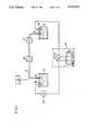
- FIG. 1is a system for high performance capillary electrophoresis according to the present invention.
- FIG. 2is a schematic diagram of an injection into the capillary column of a sample diluted in sample buffer (H 2 O).
- FIG. 3is a schematic diagram for extracting the sample buffer (H 2 O) out of the capillary column.
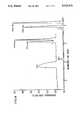
- FIG. 4is a plot showing the comparison of electropherograms with and without the sample buffer extraction in five minute injection.
- FIG. 5is a plot showing the comparison of electropherograms with and without the sample buffer extraction for the length of sample plug is on the order of 35 cm.
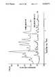
- FIG. 6is the electropherogram with the sample plug loading the entire separation column.
- FIG. 7is the electropherogram of positive charged ions separation.
- FIG. 8is a plot showing the comparison of a different duration for gravity injection with the sample buffer extraction.
- a CZE systemconsists of a capillary column 11 with an inlet end 12 and an outlet end 13; the inlet end 12 and the outlet end 13 are dipped in the buffer reservoirs 14 and 15 containing support buffer; sample introduction means 16 for introducing sample solution inside the capillary column 11 through the inlet end 12; a power supply means 17 having electrode means 18 and 19 which is disposed in the reservoirs 14 and 15 respectively; an injection detector means 20 for detecting the volume of sample solution being introduced by sample introduction means 16 through inlet end 12 into the capillary column 11; separation detector means 21 for detecting the sample components at the outlet end 13 of the capillary column 11; ammeter 22 connected between power supply means 17 and either electrode means 18 or 19 for monitoring current flow through electrolytes within capillary column 11.
- the support bufferis supplied from the reservoir 14 hydrodynamically to the capillary column 11 which is a 100 cm long, 50 ⁇ m ID, 365 ⁇ m OD fused capillary with a detector window at 35 cm from one end of the column (PolyMirco Technologies, Phoenix, AZ). Either end of the capillary column 11 might be used as the injection (inlet) side giving a detector window at 35 cm or 65 cm from the inlet end.
- the detector windowwas formed by burning off a 1 mm section of the outer polyamide coating.
- Reservoir 15 at the outlet end 13 of the capillary column 11collects the support buffer after filling the column.
- a high voltageis applied by power supply means 17 between the inlet end 12 and outlet end 13 of the capillary column 11 through electrode means 18 and 19, which are platinum wires preferably, for measuring the magnitude of electric current flow through the support buffer by ammeter 22.
- Sample introduction means 16is a syringe by which the sample solution is injected into the capillary column 11 until the injection detector means 20 responds to the sample solution passing through the window of the capillary column 11. This method allows 1/3 or 2/3 of the column to be filled rapidly depending on the location of the detector window to the inlet end of the capillary column. One can place the injection detection at the outlet end of the capillary column and fill the column completely up.
- the alternative method of sample solution introductionis to position the sample solution vial 15 cm above the floor of the buffer reservoir 14.
- the inlet end 12 of the capillary column 11is inserted into the vial and held there for 10 sec. to 20 min., which corresponds to plug lengths of 1 mm and 12 cm respectively.
- the inlet end 12 of the capillary column 11is returned to the buffer reservoir 14.
- the volume of sample solution being introducedis detected by injection detector means 20 which is an UV absorbance detector, for example, a Varian 2550 (Walnut Creek, CA) with a 100 ⁇ m slit in a modified microcell holder.
- the wavelength for analysisis 265 nm.
- sample bufferWhile sample stacking is being performed, the sample buffer is pushed out into the buffer reservoir 14 by applying reversed polarity high voltage by the power supply means 17, between the inlet 12 and outlet ends 13 of the capillary column 11 through electrode means 18 and 19.
- the current flow level through sample solution and support bufferis monitored by ammeter 22 until its magnitude reaches within 1% of the current flow value of the support buffer.
- the polarity of the electrode means 18 and 19is switched to normal, and high voltage is applied by power supply means 17 to the capillary column 11.
- the detection of the sample components at the outlet end 13 of the capillary 11is provided by separation detector means 21 which is the same type of UV absorbance detection as the injection detector means.
- the essence of keeping the high sample concentrated in sharp bandsconstitutes the method of extracting the sample buffer from the capillary column using electro-osmotic flow after the sample is stacked into the support buffer.
- the negative sample ionsare stacked at the end of the plug of sample buffer and will follow the plug as it moves through the column under the applied electric field.
- the charge on the silica capillary wallis made positive by adding Tetradecyltrimethylammonium bromide (TTAB) to the buffer, for changing the direction of the electro-osmotic flow.
- TTABTetradecyltrimethylammonium bromide
- the first step of the concentration techniqueis injection of the sample diluted in sample buffer which is shown schematically in FIG. 2.
- the sample bufferin this case is a pure water.
- the experimentswere conducted with stock solution of 1.7 ⁇ 10 -4 M PTH-Asp acid and 2.3 ⁇ 10 -4 M PTH-Glu acid made up in HPLC grade distilled water (Aldrich, WI) then diluted to 3.4 ⁇ 10 -5 M and 4.6 ⁇ 10 -5 M respectively.
- the two positive specieswere 1.5 ⁇ 10 -4 M PTH-Arg and 5.0 ⁇ 10 -5 M PTH-His.
- the support bufferwas 100 mM sodium phosphate adjusted to pH of 6.6 or 100 mM MES/HIS adjusted to pH 6.1. All chemicals were purchased from Sigma (St. Louis, MO).
- Tryptic digestwas done with 0.02 g of Cytachrome c (horse heart) and 0.001 g of trysin in 10 ml of water. The digest was kept at 37° C. for 28 hours, then diluted down to 5.0 ⁇ 10 -5 M with distilled water. The sample prepared in water was loaded into the capillary column by gravity injection.
- Removal of the water plug from the capillary columnis controlled by applying a high voltage with reverse polarity across the capillary column while monitoring the magnitude of the electric current flow through the sample solution and support buffer inside the column, and comparing it with the magnitude of the current flow through support buffer inside the column before injecting the sample solution inside the column.
- the improvement in the separation of the sample obtained by the removal of the sample buffer (water)is shown in FIG. 4.
- the experimentwas conducted under the following conditions: applied high voltage to the capillary column is on the order of 25 kV, and current flow through the support buffer inside the column is on the order of 225 ⁇ A for the phosphate buffer and 8 ⁇ A for the MES/HIS buffer.
- the electropherograms of a long sample plug (10 min. injection) with the water still in the column and with the water removedare shown in electropherograms (a) and (b), respectively.
- the resolution of the two analytesis much lower in electropherogram (a) because of the large amount of water in the column.
- the number of theoretical plates in electropherogram (a)are 2.5 ⁇ 10 4 and 2.3 ⁇ 10 4 for PTH-Asp and PTH-Glu respectively.
- the sample peaksare broadened due to a laminar flow generated by the long plug of sample buffer. The separation of the sample is not well resolved because the bulk electro-osmotic flow is increased and the electric field in the buffer portion of the column is reduced by the large amount of water.
- the number of theoretical plates in electropherogram (b), where most of the water has been removedare 4.2 ⁇ 10 4 and 4.5 ⁇ 10 4 respectively for the separation of PTH-Asp and PTH-Glu. All of the compounds in the sample plug are baseline resolved, the peak heights are greater, and the peak widths are narrower. Thus by removing the excess water after the sample is concentrated, we can improve the resolution and detectability of the sample.
- FIG. 5is a comparison between the injection of 35 cm of sample solution without and with the sample buffer removed from the column.
- the negative ionsstack up against the sample plug and since all of the electric field is dropped across the sample plug, the ions cannot separate themselves into discrete sample zones.
- the lower electropherogramshows the whole process of sample solution removal and ion separation. During the first 3 minutes of the process the sample buffer is removed. After the current reaches 99% of the support buffer current, the electrodes are switched. As seen, the remaining sample buffer passes the separation detector first, then the concentrated sample ions are detected with high resolution.
- FIG. 6is an electropherogram of an injection in which the entire column is filled with sample solution. The first 7 minutes is the removal of the sample buffer. After the current reaches 99% of the support buffer, the electrodes are switched. The sample buffer peak appears at 13 minutes and the sample ions appear later with high resolution. In other words, the sample ions in the entire column have been concentrated into very sharp zones.
- FIG. 7is an electropherogram of two positive species.
- the two sample ionare PTH-His and PTH-Arg respectively.
- the support bufferhas 1 mM TTAB in it which reverses the electro-osmotic flow of the column.
- FIG. 8A comparison of a tryptic digest of Cytachrome c at a 1 min. injection duration and a 10 min. injection duration with the water removed is shown in FIG. 8.
- the experimental datademonstrate the improvement of the concentrating effect of sample stacking on the example of gravity injection.
- the sample buffer which causes a loss of resolution in the sample stacking techniqueis extracted by electro-osmotic flow from the separation column, and further separation of the concentrated sample zone proceeds under conventional electrophoretic conditions.
Landscapes
- Health & Medical Sciences (AREA)
- Life Sciences & Earth Sciences (AREA)
- Molecular Biology (AREA)
- Chemical & Material Sciences (AREA)
- Physics & Mathematics (AREA)
- Electrochemistry (AREA)
- Chemical Kinetics & Catalysis (AREA)
- Analytical Chemistry (AREA)
- Biochemistry (AREA)
- General Health & Medical Sciences (AREA)
- General Physics & Mathematics (AREA)
- Immunology (AREA)
- Pathology (AREA)
- Investigating Or Analysing Biological Materials (AREA)
- Sampling And Sample Adjustment (AREA)
Abstract
Description
The present invention relates to capillary electrophoretic systems and methods for separation and detection of sample components inside a separation column, and more particularly to improved systems and methods for increasing detectability with a sample stacking technique in capillary electrophoresis.
Capillary zone electrophoresis (CZE) is an efficient analytical separation technique which exploits the different mobilities of sample components in an electric field whereby the sample components are organized into zones in a capillary column.
A conventional CZE system widely used in practice comprises a buffer-filled capillary column with inlet and outlet ends disposed into two reservoirs, sample introduction means for injecting analyzed sample, on-column detector means for sensing the sample zones passing the detector, and high voltage means to apply a voltage to the capillary column causing the migration and separation of the sample components inside the column (see Jorgenson, J. W; and Lukacs, K. D., Science, 1983, v222, p. 266-272).
Using CZE for the analysis of very small sample volume creates a significant detection problem associated with the detection limit of conventional detectors. Along with the traditional technique of increasing the detection sensitivity of analyzed sample components through improvement of the detection systems, a different approach has been developed to increase sensitivity by concentrating the sample components into narrower zones in the capillary column. (Mikkers, F. E. P., Everaert, F. M.; Verheggen, Th P. E. M., J. Chromatography 1979, 169, 11). This on-column concentration technique sometimes called sample stacking, is obtained by applying a high voltage across a separation column which is filled with a plug of sample in a diluted buffer and surrounding which is a buffer having much higher conductivity than the sample plug.
A number of techniques using on-column concentration of sample ions at the boundary between a plug of sample in diluted buffer and the adjacent support buffer give the enhancement in detectability of the sample components. (Moring, S. E.; Colburn, T. C.; Grossman, P. D.; and Lauer, H. H.; LC-GC, 1990, 8,34; Aebersold, R. and Morrison, H. D.; J. Chromatography 1990, 516,79; Nielen, M. W. T.; J. Chromatography 1991, 542, 173).
In the conventional CZE technique with on-column sample concentration, the attempts to significantly increase an injection sample volume lead to breakdown in resolution. Nielen injected sample volume up to 15 nl to obtain improvement of the concentration sensitivity. Better results in injecting up to 2% of the total capillary column volume were obtained by Moring, et al.
The limit in increasing the detectability of the above-described methods is the peak broadening mechanism caused by generation of laminar flow inside the capillary column. (Burgi, D. S.; and Chien, R. L.; Anal. Chem. 1991, 63, 2042). This laminar flow is generated from the mismatch of the local electro-osmotic mobilities and electric field strength between the sample buffer and the support buffer. The larger the sample volume introduced into the column, the broader the sample peaks will be. In general, a 10-fold increase in the amount of sample injected is obtainable before there is a loss in resolution due to laminar broadening. Another obstacle to a successful separation process of the sample ions is a very low strength of the electric field in the buffer bordering the long sample solution plug, and the much higher conductivity of the buffer compared to the sample plug. The electric field is low in the surrounding buffer because almost all of the electric field is dropped across the long sample plug, and that causes the electrophoretic velocity to decrease. This further limits the volume of sample solution injected into the column.
In addition, the systems for performing above methods do not provide the detection of the sample volume which allows rapid loading of the sample being introduced into the capillary column, that is very important for getting reproducability of this technique.
The foregoing disadvantage of prior art sample concentration methods and systems for performing capillary zone electrophoresis are overcome by the present invention. According to the invention, the water or diluted buffer is removed out of the column using the electro-osmotic flow while the sample components are stacked into the support buffer. The separation of the sample components is then performed in the column with minimum amount of laminar flow. This invention increases the amount of sample injected while retaining high resolution.
A system and method for high performance electrophoresis includes:
introducing consecutively a supporting buffer and a large plug of sample prepared in a diluted sample buffer which has a much lower concentration than the supporting buffer, into a separation column;
stacking sample ions at the boundary between the sample solution and the supporting buffer, while concurrently extracting the sample buffer from the separation column using the electro-osmotic flow caused due to application of reversed polarity high voltage along the separation column,
separating sample ions according to their relative electrophoretic mobilities by applying a normal polarity high voltage along the separation column after removal of the sample buffer.
A system for performing the above described method including a separation column having inlet and outlet ends which are disposed respectively, in two buffer reservoirs containing support buffer; a sample introduction means for injecting sample prepared in sample buffer into the separation column, the sample buffer having a much lower concentration than the support buffer; an injection detector means for detecting the volume of injected sample solution; separation detector means for detecting the sample components at the outlet end of the separation column, and power supply means with electrodes which are disposed in the buffer reservoirs for applying the electric field gradient along the separation column and reversing the applied voltage polarity for reversing the direction of the electro-osmotic flow thereby causing extraction of the sample buffer from the separation column.
This technique is applicable for separation of either negative charged species or positive charged species since the direction of the electro-osmotic flow which pushes out the sample buffer from the capillary column depends on the charge of the capillary column walls.
FIG. 1 is a system for high performance capillary electrophoresis according to the present invention.
FIG. 2 is a schematic diagram of an injection into the capillary column of a sample diluted in sample buffer (H2 O).
FIG. 3 is a schematic diagram for extracting the sample buffer (H2 O) out of the capillary column.
FIG. 4 is a plot showing the comparison of electropherograms with and without the sample buffer extraction in five minute injection.
FIG. 5 is a plot showing the comparison of electropherograms with and without the sample buffer extraction for the length of sample plug is on the order of 35 cm.
FIG. 6 is the electropherogram with the sample plug loading the entire separation column.
FIG. 7 is the electropherogram of positive charged ions separation.
FIG. 8 is a plot showing the comparison of a different duration for gravity injection with the sample buffer extraction.
An improved method of sample concentration in CZE was performed using a CZE system of the present invention and illustrated in FIG. 1. Referring to FIG. 1 a CZE system consists of a capillary column 11 with aninlet end 12 and an outlet end 13; theinlet end 12 and the outlet end 13 are dipped in thebuffer reservoirs inlet end 12; a power supply means 17 having electrode means 18 and 19 which is disposed in thereservoirs inlet end 12 into the capillary column 11; separation detector means 21 for detecting the sample components at the outlet end 13 of the capillary column 11;ammeter 22 connected between power supply means 17 and either electrode means 18 or 19 for monitoring current flow through electrolytes within capillary column 11.
The support buffer is supplied from thereservoir 14 hydrodynamically to the capillary column 11 which is a 100 cm long, 50 μm ID, 365 μm OD fused capillary with a detector window at 35 cm from one end of the column (PolyMirco Technologies, Phoenix, AZ). Either end of the capillary column 11 might be used as the injection (inlet) side giving a detector window at 35 cm or 65 cm from the inlet end. The detector window was formed by burning off a 1 mm section of the outer polyamide coating.
Sample introduction means 16 is a syringe by which the sample solution is injected into the capillary column 11 until the injection detector means 20 responds to the sample solution passing through the window of the capillary column 11. This method allows 1/3 or 2/3 of the column to be filled rapidly depending on the location of the detector window to the inlet end of the capillary column. One can place the injection detection at the outlet end of the capillary column and fill the column completely up.
The alternative method of sample solution introduction is to position the sample solution vial 15 cm above the floor of thebuffer reservoir 14. Theinlet end 12 of the capillary column 11 is inserted into the vial and held there for 10 sec. to 20 min., which corresponds to plug lengths of 1 mm and 12 cm respectively. After injection, theinlet end 12 of the capillary column 11 is returned to thebuffer reservoir 14. The volume of sample solution being introduced is detected by injection detector means 20 which is an UV absorbance detector, for example, a Varian 2550 (Walnut Creek, CA) with a 100 μm slit in a modified microcell holder. The wavelength for analysis is 265 nm.
While sample stacking is being performed, the sample buffer is pushed out into thebuffer reservoir 14 by applying reversed polarity high voltage by the power supply means 17, between theinlet 12 and outlet ends 13 of the capillary column 11 through electrode means 18 and 19. The current flow level through sample solution and support buffer is monitored byammeter 22 until its magnitude reaches within 1% of the current flow value of the support buffer.
For separation of the sample into its components, the polarity of the electrode means 18 and 19 is switched to normal, and high voltage is applied by power supply means 17 to the capillary column 11. The detection of the sample components at the outlet end 13 of the capillary 11 is provided by separation detector means 21 which is the same type of UV absorbance detection as the injection detector means.
The essence of keeping the high sample concentrated in sharp bands constitutes the method of extracting the sample buffer from the capillary column using electro-osmotic flow after the sample is stacked into the support buffer.
With a negatively charged silica capillary wall, the negative sample ions are stacked at the end of the plug of sample buffer and will follow the plug as it moves through the column under the applied electric field. For separation of positive sample ions, the charge on the silica capillary wall is made positive by adding Tetradecyltrimethylammonium bromide (TTAB) to the buffer, for changing the direction of the electro-osmotic flow.
The first step of the concentration technique is injection of the sample diluted in sample buffer which is shown schematically in FIG. 2. The sample buffer in this case is a pure water. The experiments were conducted with stock solution of 1.7×10⁻⁴ M PTH-Asp acid and 2.3×10⁻⁴ M PTH-Glu acid made up in HPLC grade distilled water (Aldrich, WI) then diluted to 3.4×10⁻⁵ M and 4.6×10⁻⁵ M respectively. The two positive species were 1.5×10⁻⁴ M PTH-Arg and 5.0×10⁻⁵ M PTH-His. The support buffer was 100 mM sodium phosphate adjusted to pH of 6.6 or 100 mM MES/HIS adjusted to pH 6.1. All chemicals were purchased from Sigma (St. Louis, MO). Tryptic digest was done with 0.02 g of Cytachrome c (horse heart) and 0.001 g of trysin in 10 ml of water. The digest was kept at 37° C. for 28 hours, then diluted down to 5.0×10⁻⁵ M with distilled water. The sample prepared in water was loaded into the capillary column by gravity injection.
Since the electrophoretic velocity of the ions inside the water plug is much faster than the bulk electro-osmotic velocity, application of high voltage with reversed polarity immediately after loading the sample causes extraction of the water plug (only) from the capillary column as shown in the FIG. 3. The negative ions are stacked into a thin zone on the back side of the sample plug.
Removal of the water plug from the capillary column is controlled by applying a high voltage with reverse polarity across the capillary column while monitoring the magnitude of the electric current flow through the sample solution and support buffer inside the column, and comparing it with the magnitude of the current flow through support buffer inside the column before injecting the sample solution inside the column.
When the current flow reaches 95% to 99% of the current flow of homogeneous systems, the voltage is disconnected. For further separation into components of the stacked sample ions, it is necessary to switch polarity of the electrodes to the normal polarity and apply high voltage having a comparable value to the high voltage being applied to the capillary column before sample solution injection.
The improvement in the separation of the sample obtained by the removal of the sample buffer (water) is shown in FIG. 4. The experiment was conducted under the following conditions: applied high voltage to the capillary column is on the order of 25 kV, and current flow through the support buffer inside the column is on the order of 225 μA for the phosphate buffer and 8 μA for the MES/HIS buffer. The electropherograms of a long sample plug (10 min. injection) with the water still in the column and with the water removed are shown in electropherograms (a) and (b), respectively. The resolution of the two analytes is much lower in electropherogram (a) because of the large amount of water in the column. The number of theoretical plates in electropherogram (a) are 2.5×10⁴ and 2.3×10⁴ for PTH-Asp and PTH-Glu respectively. The sample peaks are broadened due to a laminar flow generated by the long plug of sample buffer. The separation of the sample is not well resolved because the bulk electro-osmotic flow is increased and the electric field in the buffer portion of the column is reduced by the large amount of water. In constrast, the number of theoretical plates in electropherogram (b), where most of the water has been removed, are 4.2×10⁴ and 4.5×10⁴ respectively for the separation of PTH-Asp and PTH-Glu. All of the compounds in the sample plug are baseline resolved, the peak heights are greater, and the peak widths are narrower. Thus by removing the excess water after the sample is concentrated, we can improve the resolution and detectability of the sample.
FIG. 5 is a comparison between the injection of 35 cm of sample solution without and with the sample buffer removed from the column. As seen in the upper electropherogram, the negative ions stack up against the sample plug and since all of the electric field is dropped across the sample plug, the ions cannot separate themselves into discrete sample zones. The lower electropherogram shows the whole process of sample solution removal and ion separation. During the first 3 minutes of the process the sample buffer is removed. After the current reaches 99% of the support buffer current, the electrodes are switched. As seen, the remaining sample buffer passes the separation detector first, then the concentrated sample ions are detected with high resolution.
FIG. 6 is an electropherogram of an injection in which the entire column is filled with sample solution. The first 7 minutes is the removal of the sample buffer. After the current reaches 99% of the support buffer, the electrodes are switched. The sample buffer peak appears at 13 minutes and the sample ions appear later with high resolution. In other words, the sample ions in the entire column have been concentrated into very sharp zones.
FIG. 7 is an electropherogram of two positive species. The two sample ion are PTH-His and PTH-Arg respectively. The support buffer has 1 mM TTAB in it which reverses the electro-osmotic flow of the column.
A comparison of a tryptic digest of Cytachrome c at a 1 min. injection duration and a 10 min. injection duration with the water removed is shown in FIG. 8. One can see more peaks and greater peak heights using the concentrating method in the tryptic digest analysis; however, there is no one-to-one match of peaks between the two types of injection, possibly due to concentrating effects.
The experimental data demonstrate the improvement of the concentrating effect of sample stacking on the example of gravity injection. The sample buffer which causes a loss of resolution in the sample stacking technique is extracted by electro-osmotic flow from the separation column, and further separation of the concentrated sample zone proceeds under conventional electrophoretic conditions.
Claims (33)
1. A method for improving sample concentration in capillary electrophoresis comprising the steps of:
substantially filling a separation column with a first buffer;
measuring the magnitude of a current flow through said first buffer inside said separation column by applying a first voltage across said separation column for a period of time necessary for performing the measurement of said first current flow to determine the first current flow value;
obtaining sample solution by preparing a sample in a second buffer, said second buffer having concentration lower than said first buffer;
introducing a plug of said sample solution into said separation column adjacent to said first buffer;
concentrating ions of said sample at the boundary between said first buffer and said sample solution, and substantially extracting said second buffer from said separation column by applying a second voltage across said separation column and concurrently monitoring the magnitude of current flow through said sample solution and first buffer within said separation column, said second voltage having an opposite polarity to said first voltage;
applying a third voltage across said separation column for separating said sample into its components thereby providing a signal when each component is detected, said third voltage having opposite polarity to said second voltage.
2. The method of claim 1 wherein said first buffer has identical composition as said second buffer.
3. The method of claim 1 wherein said second buffer is pure water.
4. The method of claim 1 wherein said plug of said sample solution is introduced hydrodynamically into said separation column.
5. The method of claim 4 wherein said plug of said sample solution is introduced into said separation column until obtaining a response from said injection detector.
6. The method of claim 4 wherein a length of said plug of said sample solution is greater than 2% of a length of said separation column.
7. The method of claim 4 wherein said plug of said sample solution is introduced into said separation column until the length of said plug of said sample solution is comparable with the length of said separation column.
8. The method of claim 1 wherein said first voltage and said third voltage have a comparable value.
9. The method of claim 1 wherein step of substantially extracting said second buffer from said separation column comprises:
applying said second voltage to achieve a second current flow having an opposite direction to said first current flow, maintaining said second voltage until said second current flow increases to a selected value, said selected value less than said first current flow value.
10. The method of claim 9 wherein said second current flow is substantially 99% of said first current flow.
11. A capillary electrophoresis system comprising:
a separation column having inlet and outlet ends;
a support buffer within said separation column;
a sample introduction means for loading a plug of a sample solution into said separation column, said sample solution being a sample diluted in a sample buffer;
an injection detector means for detecting the volume of said sample diluted in said sample buffer being introduced in said separation column at said inlet end;
a separation detector means for detecting the sample components at the outlet end of said separation column;
a power supply means having electrode means to apply an electric field along said separation column for concentrating sample ions at the boundary between said support buffer and said sample solution within said separation column and for extraction of said sample buffer out of said column by switching the polarity of said electric field of said electrode means thereby translating said sample along said column for separating said sample into components thereof by again reversing the polarity of said electric field of said electrode means;
a measuring means for measuring the magnitude of electric current flow through said support buffer and said sample diluted in said sample buffer within said separation column.
12. The system of claim 11 wherein said separation column is a capillary tube.
13. The system of claim 12 further comprising a first and a second buffer reservoir for containing said support buffer wherein said electrode means of said power supply means are disposed to apply electric field along said capillary tube, said first and said second buffer reservoir are disposed at said inlet and said outlet ends of said capillary tube respectively.
14. The system of claim 11 wherein said measuring means is connected between said power supply means and any one of said electrode means.
15. The system of claim 1 wherein said injection detector is placed at a selected distance from said inlet end of said separation column for detecting the volume of the injected said sample solution.
16. The process for high performance capillary electrophoresis by increasing concentration of the positive charged ions of the sample comprising the steps of:
substantially filling a separation column with first buffer;
measuring the magnitude of a current flow through said first buffer inside said separation column by applying a first voltage along said separation column for a period of time necessary for performing the measurement of said first current flow to determine the first current flow value;
obtaining sample solution by preparing a sample in a second buffer, said second buffer having concentration lower than said first buffer;
introducing a plug of said sample solution into said separation column adjacent to said first buffer;
concentrating positive charged ions of the sample at the boundary between said first buffer and said sample solution, and substantially extracting said second buffer from said separation column by applying a second voltage along said separation column and concurrently monitoring the magnitude of current flow through said sample solution and first buffer within said separation column, said second voltage having an opposite polarity to said first voltage;
applying a third voltage along said separation column for separating said sample into its components thereby providing a signal when each component is detected, said third voltage having opposite polarity to said second voltage.
17. The process of claim 16 wherein said separation column is a capillary tube having silica walls;
18. The process of claim 16 wherein said second buffer having a modifier to charge said silica walls of said capillary tube positively.
19. The process of claim 18 wherein said modifier is cetyltrimethylammonium bromide.
20. The process of claim 16 wherein said first buffer has identical composition as said second buffer.
21. The process of claim 16 wherein said second buffer is pure water.
22. The process of claim 16 wherein said plug of said sample solution is introduced hydrodynamically into said separation column.
23. The process of claim 16 wherein said first voltage and said third voltage have a comparable value.
24. The process of claim 16 wherein step of substantially extracting said second buffer from said separation column comprises:
applying said second voltage to achieve a second current flow having an opposite direction to said first current flow, maintaining said second voltage until said second current flow increases to a selected value, said selected value less than said first current flow value.
25. The process of claim 24 wherein said second current flow is substantially 99% of said first current flow.
26. The process for high performance capillary electrophoresis by increasing concentration of the negative charged ions of the sample comprising the steps of:
substantially filling a separation column with first buffer,
measuring the magnitude of a current flow through said first buffer inside said separation column by applying a first voltage along said separation column for a period of time necessary for performing the measurement of said first current flow to determine the first current flow value;
obtaining sample solution by preparing a sample in a second buffer, said second buffer having concentration lower than said first buffer;
injecting a plug of said sample solution into said separation column adjacent to said first buffer;
concentrating negative charged ions of the sample at the boundary between said first buffer and said sample solution and substantially extracting said second buffer from said separation column by applying a second voltage along said separation column and concurrently monitoring the magnitude of current flow through said sample solution and first buffer within said separation column, said second voltage having an opposite polarity to said first voltage;
applying a third voltage along said separation column for separating said sample into its components thereby providing a signal when each component is detected, said third voltage having opposite polarity to said second voltage.
27. The process of claim 26 wherein said separation column is a capillary tube having silica walls.
28. The process of claim 26 wherein said first buffer has identical composition as said second buffer.
29. The process of claim 26 wherein said second buffer is pure water.
30. The process of claim 26 wherein said plug of said sample solution is introduced hydrodynamically into said separation column;
31. The process of claim 26 wherein said first voltage and said third voltage have a comparable value.
32. The process of claim 26 wherein step of substantially extracting said second buffer from said separation column comprises:
applying said second voltage to achieve a second current flow having an opposite direction to said first current flow, maintaining said second voltage until said second current flow increases to a selected value, said selected value less than said first current flow value.
33. The process of claim 32 wherein said second current flow is substantially 99% of said first current flow.
Priority Applications (5)
| Application Number | Priority Date | Filing Date | Title |
|---|---|---|---|
| US07/771,575US5116471A (en) | 1991-10-04 | 1991-10-04 | System and method for improving sample concentration in capillary electrophoresis |
| PCT/US1992/008371WO1993007478A1 (en) | 1991-10-04 | 1992-09-30 | System and method for improving sample concentration in capillary electrophoresis |
| DE69217197TDE69217197T2 (en) | 1991-10-04 | 1992-09-30 | DEVICE AND METHOD FOR IMPROVED SAMPLE CONCENTRATION IN CAPILLARY ELECTROPHORESIS |
| EP92921871AEP0560974B1 (en) | 1991-10-04 | 1992-09-30 | System and method for improving sample concentration in capillary electrophoresis |
| JP5507057AJPH06505563A (en) | 1991-10-04 | 1992-09-30 | Systems and methods for improved sample concentration in capillary electrophoresis |
Applications Claiming Priority (1)
| Application Number | Priority Date | Filing Date | Title |
|---|---|---|---|
| US07/771,575US5116471A (en) | 1991-10-04 | 1991-10-04 | System and method for improving sample concentration in capillary electrophoresis |
Publications (1)
| Publication Number | Publication Date |
|---|---|
| US5116471Atrue US5116471A (en) | 1992-05-26 |
Family
ID=25092260
Family Applications (1)
| Application Number | Title | Priority Date | Filing Date |
|---|---|---|---|
| US07/771,575Expired - LifetimeUS5116471A (en) | 1991-10-04 | 1991-10-04 | System and method for improving sample concentration in capillary electrophoresis |
Country Status (5)
| Country | Link |
|---|---|
| US (1) | US5116471A (en) |
| EP (1) | EP0560974B1 (en) |
| JP (1) | JPH06505563A (en) |
| DE (1) | DE69217197T2 (en) |
| WO (1) | WO1993007478A1 (en) |
Cited By (45)
| Publication number | Priority date | Publication date | Assignee | Title |
|---|---|---|---|---|
| US5340452A (en)* | 1991-02-01 | 1994-08-23 | Beckman Instruments, Inc. | On-column preconcentration of samples in capillary electrophoresis |
| WO1994025144A1 (en)* | 1993-05-05 | 1994-11-10 | Amrad Corporation Limited | Electrophoretic resolution of charged molecules |
| US5376249A (en)* | 1992-11-25 | 1994-12-27 | Perseptive Biosystems, Inc. | Analysis utilizing isoelectric focusing |
| AU663260B2 (en)* | 1993-05-05 | 1995-09-28 | Amrad Operations Pty. Limited | Electrophoretic resolution of charged molecules |
| US5573651A (en)* | 1995-04-17 | 1996-11-12 | The Dow Chemical Company | Apparatus and method for flow injection analysis |
| US5766435A (en)* | 1993-01-26 | 1998-06-16 | Bio-Rad Laboratories, Inc. | Concentration of biological samples on a microliter scale and analysis by capillary electrophoresis |
| US5810985A (en)* | 1992-09-14 | 1998-09-22 | Purdue Research Foundation | Electrophoretically mediated chemical analysis |
| US5880071A (en)* | 1996-06-28 | 1999-03-09 | Caliper Technologies Corporation | Electropipettor and compensation means for electrophoretic bias |
| US5935522A (en)* | 1990-06-04 | 1999-08-10 | University Of Utah Research Foundation | On-line DNA analysis system with rapid thermal cycling |
| US5958202A (en)* | 1992-09-14 | 1999-09-28 | Perseptive Biosystems, Inc. | Capillary electrophoresis enzyme immunoassay |
| US5958203A (en)* | 1996-06-28 | 1999-09-28 | Caliper Technologies Corportion | Electropipettor and compensation means for electrophoretic bias |
| US6062261A (en)* | 1998-12-16 | 2000-05-16 | Lockheed Martin Energy Research Corporation | MicrofluIdic circuit designs for performing electrokinetic manipulations that reduce the number of voltage sources and fluid reservoirs |
| US6174670B1 (en) | 1996-06-04 | 2001-01-16 | University Of Utah Research Foundation | Monitoring amplification of DNA during PCR |
| US6322683B1 (en) | 1999-04-14 | 2001-11-27 | Caliper Technologies Corp. | Alignment of multicomponent microfabricated structures |
| WO2002037091A1 (en)* | 2000-10-31 | 2002-05-10 | Caliper Technologies Corp. | Microfluidic methods, devices and systems for in situ material concentration |
| US20020070166A1 (en)* | 2000-12-07 | 2002-06-13 | Board Of Governors Of The University Of Alberta | Sample purification on a microfluidic device |
| WO2002050095A1 (en)* | 2000-12-18 | 2002-06-27 | Trustees Of Princeton University | Fractionation of macro-molecules using asymmetric pulsed field electrophoresis |
| US6428666B1 (en) | 1999-02-22 | 2002-08-06 | Sandia National Laboratories | Electrokinetic concentration of charged molecules |
| US6475441B1 (en) | 1997-06-09 | 2002-11-05 | Caliper Technologies Corp. | Method for in situ concentration and/or dilution of materials in microfluidic systems |
| US20030057092A1 (en)* | 2000-10-31 | 2003-03-27 | Caliper Technologies Corp. | Microfluidic methods, devices and systems for in situ material concentration |
| US20030062309A1 (en)* | 2001-08-13 | 2003-04-03 | The Board Of Trustees Of The Leland Stanford Junior University | Bonded phase photopolymerized sol-gel column and associated methods |
| US20030062833A1 (en)* | 2001-10-03 | 2003-04-03 | Wen-Yen Tai | Mini-type decorative bulb capable of emitting light through entire circumferential face |
| US20030062310A1 (en)* | 2000-02-18 | 2003-04-03 | The Board Of Trustees Of The Leland Stanford Junior University | Separation column having a photopolymerized sol-gel component and associated methods |
| US20030075444A1 (en)* | 2001-10-19 | 2003-04-24 | Huang Lotien Richard | Method and apparatus for generating electric fields and flow distributions for rapidly separating molecules |
| EP1367388A1 (en) | 2002-05-31 | 2003-12-03 | Hitachi High-Technologies Corporation | Capillary electrophoresis apparatus and method |
| US20040055940A1 (en)* | 2000-02-18 | 2004-03-25 | Zare Richard N. | Fused-silica capillaries with photopolymer components |
| US6719535B2 (en)* | 2002-01-31 | 2004-04-13 | Eksigent Technologies, Llc | Variable potential electrokinetic device |
| US20040144648A1 (en)* | 2000-01-12 | 2004-07-29 | Jacobson Stephen C. | Microfluidic device and method for focusing, segmenting, and dispensing of a fluid stream |
| US6787338B2 (en) | 1990-06-04 | 2004-09-07 | The University Of Utah | Method for rapid thermal cycling of biological samples |
| US20040259269A1 (en)* | 2003-06-20 | 2004-12-23 | Groton Biosystems | Method for detection of molecular species in a crude sample using capillary electrophoresis |
| US20050011761A1 (en)* | 2000-10-31 | 2005-01-20 | Caliper Technologies Corp. | Microfluidic methods, devices and systems for in situ material concentration |
| US20050064582A1 (en)* | 1990-06-04 | 2005-03-24 | University Of Utah Research Foundation | Container for carrying out and monitoring biological processes |
| US6890411B1 (en) | 1998-06-11 | 2005-05-10 | Arizona Board Of Regents | Control of flow and materials for micro devices |
| US7081226B1 (en) | 1996-06-04 | 2006-07-25 | University Of Utah Research Foundation | System and method for fluorescence monitoring |
| US20070141550A1 (en)* | 2003-12-12 | 2007-06-21 | Zare Richard N | Immobilized-enzyme microreactor devices for characterization of biomolecular analytes and associated methods |
| US20070148014A1 (en)* | 2005-11-23 | 2007-06-28 | Anex Deon S | Electrokinetic pump designs and drug delivery systems |
| US20070144909A1 (en)* | 2002-10-18 | 2007-06-28 | Eksigent Technologies, Llc | Electrokinetic Pump Having Capacitive Electrodes |
| US20070284308A1 (en)* | 2006-06-12 | 2007-12-13 | Zare Richard N | Immobilized-enzyme microreactor devices for characterization of biomolecular analytes and associated methods |
| US20090148308A1 (en)* | 2007-12-11 | 2009-06-11 | Saleki Mansour A | Electrokinetic Pump with Fixed Stroke Volume |
| US7867592B2 (en) | 2007-01-30 | 2011-01-11 | Eksigent Technologies, Inc. | Methods, compositions and devices, including electroosmotic pumps, comprising coated porous surfaces |
| WO2011150424A1 (en)* | 2010-05-28 | 2011-12-01 | Mehdi Moini | Handheld/portable ultrafast capillary electrophoresis with adjustable porous tip in conjunction with mass spectrometry |
| CN104049025A (en)* | 2014-01-23 | 2014-09-17 | 杭州师范大学 | Capillary electrophoresis analysis system utilizing micro-injection pump to drive liquid flows |
| US8979511B2 (en) | 2011-05-05 | 2015-03-17 | Eksigent Technologies, Llc | Gel coupling diaphragm for electrokinetic delivery systems |
| CN109444246A (en)* | 2018-11-01 | 2019-03-08 | 宁波大学 | A kind of transient state capillary isotachophoresis device and method based on polarity of voltage conversion |
| US20220042079A1 (en)* | 2018-12-20 | 2022-02-10 | Sergey N. Krylov | Binder Selection Using Capollary Electrophoresis |
- 1991
- 1991-10-04USUS07/771,575patent/US5116471A/ennot_activeExpired - Lifetime
- 1992
- 1992-09-30EPEP92921871Apatent/EP0560974B1/ennot_activeExpired - Lifetime
- 1992-09-30DEDE69217197Tpatent/DE69217197T2/ennot_activeExpired - Fee Related
- 1992-09-30JPJP5507057Apatent/JPH06505563A/enactivePending
- 1992-09-30WOPCT/US1992/008371patent/WO1993007478A1/enactiveIP Right Grant
Non-Patent Citations (14)
| Title |
|---|
| Dean S. Burgi & Ring Ling Chien Optimization in Sample Stacking for High Performance Capillary Electrophoresis Analytical Chemistry, vol. 63, No. 18 (1991) 2042 2047.* |
| Dean S. Burgi & Ring-Ling Chien "Optimization in Sample Stacking for High-Performance Capillary Electrophoresis" Analytical Chemistry, vol. 63, No. 18 (1991) 2042-2047. |
| F. E. B. Mikkers, F. M. Everaerts, & Th. P. E. M. Verheggen "High-Performance Zone Electrophoresis" Journal of Chromatography 169 (1979) 11-20. |
| F. E. B. Mikkers, F. M. Everaerts, & Th. P. E. M. Verheggen High Performance Zone Electrophoresis Journal of Chromatography 169 (1979) 11 20.* |
| Henk H. Lauer et al. "Analytical Aspects of an Automated Capillary Electrophoresis System" LC-GC vol. 6, No. 1 (1990) 34-46. |
| Henk H. Lauer et al. Analytical Aspects of an Automated Capillary Electrophoresis System LC GC vol. 6, No. 1 (1990) 34 46.* |
| Jorgenson, James W. et al. "Capillary Zone Electrophoresis", Science, vol. 222, (1983), pp. 266-272. |
| Jorgenson, James W. et al. Capillary Zone Electrophoresis , Science, vol. 222, (1983), pp. 266 272.* |
| Moring, Stephen E., "Analytical Aspects of an Automated Capillary Electrophoresis System," LC-GC, vol. 8, No. 1 (1990) 34-46. |
| Moring, Stephen E., Analytical Aspects of an Automated Capillary Electrophoresis System, LC GC, vol. 8, No. 1 (1990) 34 46.* |
| Nielen, M. W. F., "Impact of Experimental Parameters on the Resolution of Positional Isomers of Aminobenzoic Acid in Capillary Zone Electrophoresis," Journal of Chromatography, 542 (1991) 173-183. |
| Nielen, M. W. F., Impact of Experimental Parameters on the Resolution of Positional Isomers of Aminobenzoic Acid in Capillary Zone Electrophoresis, Journal of Chromatography, 542 (1991) 173 183.* |
| Ruedi Aebersold & Hamish D. Morrison "Analysis of dilute peptide samples by capillary zone electrophoresis" Journal of Chromatography 516 (1990) 79-88. |
| Ruedi Aebersold & Hamish D. Morrison Analysis of dilute peptide samples by capillary zone electrophoresis Journal of Chromatography 516 (1990) 79 88.* |
Cited By (90)
| Publication number | Priority date | Publication date | Assignee | Title |
|---|---|---|---|---|
| US20050064582A1 (en)* | 1990-06-04 | 2005-03-24 | University Of Utah Research Foundation | Container for carrying out and monitoring biological processes |
| US7745205B2 (en) | 1990-06-04 | 2010-06-29 | University Of Utah Research Foundation | Container for carrying out and monitoring biological processes |
| US6787338B2 (en) | 1990-06-04 | 2004-09-07 | The University Of Utah | Method for rapid thermal cycling of biological samples |
| US7273749B1 (en) | 1990-06-04 | 2007-09-25 | University Of Utah Research Foundation | Container for carrying out and monitoring biological processes |
| US5935522A (en)* | 1990-06-04 | 1999-08-10 | University Of Utah Research Foundation | On-line DNA analysis system with rapid thermal cycling |
| US5340452A (en)* | 1991-02-01 | 1994-08-23 | Beckman Instruments, Inc. | On-column preconcentration of samples in capillary electrophoresis |
| US5958202A (en)* | 1992-09-14 | 1999-09-28 | Perseptive Biosystems, Inc. | Capillary electrophoresis enzyme immunoassay |
| US5810985A (en)* | 1992-09-14 | 1998-09-22 | Purdue Research Foundation | Electrophoretically mediated chemical analysis |
| US5376249A (en)* | 1992-11-25 | 1994-12-27 | Perseptive Biosystems, Inc. | Analysis utilizing isoelectric focusing |
| US5766435A (en)* | 1993-01-26 | 1998-06-16 | Bio-Rad Laboratories, Inc. | Concentration of biological samples on a microliter scale and analysis by capillary electrophoresis |
| AU663260B2 (en)* | 1993-05-05 | 1995-09-28 | Amrad Operations Pty. Limited | Electrophoretic resolution of charged molecules |
| WO1994025144A1 (en)* | 1993-05-05 | 1994-11-10 | Amrad Corporation Limited | Electrophoretic resolution of charged molecules |
| US5573651A (en)* | 1995-04-17 | 1996-11-12 | The Dow Chemical Company | Apparatus and method for flow injection analysis |
| US20060029965A1 (en)* | 1996-06-04 | 2006-02-09 | Wittwer Carl T | System for fluorescence monitoring |
| US6569627B2 (en) | 1996-06-04 | 2003-05-27 | University Of Utah Research Foundation | Monitoring hybridization during PCR using SYBR™ Green I |
| US6174670B1 (en) | 1996-06-04 | 2001-01-16 | University Of Utah Research Foundation | Monitoring amplification of DNA during PCR |
| US20090258414A1 (en)* | 1996-06-04 | 2009-10-15 | Wittwer Carl T | System for fluorescence monitoring |
| US6232079B1 (en) | 1996-06-04 | 2001-05-15 | University Of Utah Research Foundation | PCR method for nucleic acid quantification utilizing second or third order rate constants |
| US6245514B1 (en) | 1996-06-04 | 2001-06-12 | University Of Utah Research Foundation | Fluorescent donor-acceptor pair with low spectral overlap |
| US20090311673A1 (en)* | 1996-06-04 | 2009-12-17 | Wittwer Carl T | Nucleic acid amplification methods |
| US7670832B2 (en) | 1996-06-04 | 2010-03-02 | University Of Utah Research Foundation | System for fluorescence monitoring |
| US7081226B1 (en) | 1996-06-04 | 2006-07-25 | University Of Utah Research Foundation | System and method for fluorescence monitoring |
| US6042709A (en)* | 1996-06-28 | 2000-03-28 | Caliper Technologies Corp. | Microfluidic sampling system and methods |
| US6080295A (en)* | 1996-06-28 | 2000-06-27 | Caliper Technologies Corporation | Electropipettor and compensation means for electrophoretic bias |
| US5880071A (en)* | 1996-06-28 | 1999-03-09 | Caliper Technologies Corporation | Electropipettor and compensation means for electrophoretic bias |
| US5958203A (en)* | 1996-06-28 | 1999-09-28 | Caliper Technologies Corportion | Electropipettor and compensation means for electrophoretic bias |
| US6482364B2 (en) | 1996-06-28 | 2002-11-19 | Caliper Technologies Corp. | Microfluidic systems including pipettor elements |
| US5972187A (en)* | 1996-06-28 | 1999-10-26 | Caliper Technologies Corporation | Electropipettor and compensation means for electrophoretic bias |
| US6287520B1 (en) | 1996-06-28 | 2001-09-11 | Caliper Technologies Corp. | Electropipettor and compensation means for electrophoretic bias |
| US7001496B2 (en) | 1996-06-28 | 2006-02-21 | Caliper Life Sciences, Inc. | Electropipettor and compensation means for electrophoretic bias |
| US20030085126A1 (en)* | 1996-06-28 | 2003-05-08 | Caliper Technologies Corp. | Electropipettor and compensation means for electrophoretic bias |
| US6547942B1 (en) | 1996-06-28 | 2003-04-15 | Caliper Technologies Corp. | Electropipettor and compensation means for electrophoretic bias |
| US6475441B1 (en) | 1997-06-09 | 2002-11-05 | Caliper Technologies Corp. | Method for in situ concentration and/or dilution of materials in microfluidic systems |
| US6890411B1 (en) | 1998-06-11 | 2005-05-10 | Arizona Board Of Regents | Control of flow and materials for micro devices |
| US6213151B1 (en)* | 1998-12-16 | 2001-04-10 | Ut-Battelle, Llc | Microfluidic circuit designs for performing fluidic manipulations that reduce the number of pumping sources and fluid reservoirs |
| US6062261A (en)* | 1998-12-16 | 2000-05-16 | Lockheed Martin Energy Research Corporation | MicrofluIdic circuit designs for performing electrokinetic manipulations that reduce the number of voltage sources and fluid reservoirs |
| US6428666B1 (en) | 1999-02-22 | 2002-08-06 | Sandia National Laboratories | Electrokinetic concentration of charged molecules |
| US20060261033A1 (en)* | 1999-04-14 | 2006-11-23 | Wolk Jeffrey A | Alignment of multicomponent microfabricated structures |
| US6322683B1 (en) | 1999-04-14 | 2001-11-27 | Caliper Technologies Corp. | Alignment of multicomponent microfabricated structures |
| US7422669B2 (en) | 2000-01-12 | 2008-09-09 | Ut-Battelle, Llc | Microfluidic device and method for focusing, segmenting, and dispensing of a fluid stream |
| US20040144648A1 (en)* | 2000-01-12 | 2004-07-29 | Jacobson Stephen C. | Microfluidic device and method for focusing, segmenting, and dispensing of a fluid stream |
| US6790328B2 (en) | 2000-01-12 | 2004-09-14 | Ut-Battelle, Llc | Microfluidic device and method for focusing, segmenting, and dispensing of a fluid stream |
| US6875348B2 (en) | 2000-02-18 | 2005-04-05 | The Board Of Trustees Of The Leland Stanford Junior University | Separation column having a photopolymerized sol-gel component and associated methods |
| US20040055940A1 (en)* | 2000-02-18 | 2004-03-25 | Zare Richard N. | Fused-silica capillaries with photopolymer components |
| US20030062310A1 (en)* | 2000-02-18 | 2003-04-03 | The Board Of Trustees Of The Leland Stanford Junior University | Separation column having a photopolymerized sol-gel component and associated methods |
| US6986841B2 (en) | 2000-02-18 | 2006-01-17 | Zare Richard N | Fused-silica capillaries with photopolymer components |
| WO2002037091A1 (en)* | 2000-10-31 | 2002-05-10 | Caliper Technologies Corp. | Microfluidic methods, devices and systems for in situ material concentration |
| US20050011761A1 (en)* | 2000-10-31 | 2005-01-20 | Caliper Technologies Corp. | Microfluidic methods, devices and systems for in situ material concentration |
| US20030057092A1 (en)* | 2000-10-31 | 2003-03-27 | Caliper Technologies Corp. | Microfluidic methods, devices and systems for in situ material concentration |
| EP1330641A4 (en)* | 2000-10-31 | 2006-05-03 | Caliper Life Sciences Inc | Microfluidic methods, devices and systems for in situ material concentration |
| US6695009B2 (en) | 2000-10-31 | 2004-02-24 | Caliper Technologies Corp. | Microfluidic methods, devices and systems for in situ material concentration |
| US20020070166A1 (en)* | 2000-12-07 | 2002-06-13 | Board Of Governors Of The University Of Alberta | Sample purification on a microfluidic device |
| US6881317B2 (en) | 2000-12-18 | 2005-04-19 | The Trustees Of Princeton University | Fractionation of macro-molecules using asymmetric pulsed field electrophoresis |
| WO2002050095A1 (en)* | 2000-12-18 | 2002-06-27 | Trustees Of Princeton University | Fractionation of macro-molecules using asymmetric pulsed field electrophoresis |
| US20020098504A1 (en)* | 2000-12-18 | 2002-07-25 | Huang Lotien Richard | Fractionation of macro-molecules using asymmetric pulsed field electrophoresis |
| US20090014332A1 (en)* | 2000-12-18 | 2009-01-15 | The Trustees Of Princeton University | Fractionation of Macro-Molecules Using Asymmetric Pulsed Field Electrophoresis |
| US6866785B2 (en) | 2001-08-13 | 2005-03-15 | The Board Of Trustees Of The Leland Stanford Junior University | Photopolymerized sol-gel column and associated methods |
| US20030062309A1 (en)* | 2001-08-13 | 2003-04-03 | The Board Of Trustees Of The Leland Stanford Junior University | Bonded phase photopolymerized sol-gel column and associated methods |
| US6884346B2 (en) | 2001-08-13 | 2005-04-26 | The Board Of Trustees Of The Leland Stanford Junior University | Bonded phase photopolymerized sol-gel column and associated methods |
| US20030062308A1 (en)* | 2001-08-13 | 2003-04-03 | Zare Richard N. | Photopolymerized sol-gel column and associated methods |
| US20030062833A1 (en)* | 2001-10-03 | 2003-04-03 | Wen-Yen Tai | Mini-type decorative bulb capable of emitting light through entire circumferential face |
| US20030075444A1 (en)* | 2001-10-19 | 2003-04-24 | Huang Lotien Richard | Method and apparatus for generating electric fields and flow distributions for rapidly separating molecules |
| US7597791B2 (en) | 2001-10-19 | 2009-10-06 | The Trustees Of Princeton University | Method and apparatus for generating electric fields and flow distributions for rapidly separating molecules |
| US6719535B2 (en)* | 2002-01-31 | 2004-04-13 | Eksigent Technologies, Llc | Variable potential electrokinetic device |
| US7399398B2 (en) | 2002-01-31 | 2008-07-15 | Eksigent Technologies, Llc | Variable potential electrokinetic devices |
| US20040163959A1 (en)* | 2002-01-31 | 2004-08-26 | Rakestraw David J. | Variable potential electrokinetic devices |
| US7250096B2 (en) | 2002-05-31 | 2007-07-31 | Hitachi High-Technologies Corporation | Capillary electrophoresis apparatus and method |
| EP1367388A1 (en) | 2002-05-31 | 2003-12-03 | Hitachi High-Technologies Corporation | Capillary electrophoresis apparatus and method |
| US20040018638A1 (en)* | 2002-05-31 | 2004-01-29 | Tomohiro Shoji | Capillary electrophoresis apparatus and method |
| US8715480B2 (en) | 2002-10-18 | 2014-05-06 | Eksigent Technologies, Llc | Electrokinetic pump having capacitive electrodes |
| US20070144909A1 (en)* | 2002-10-18 | 2007-06-28 | Eksigent Technologies, Llc | Electrokinetic Pump Having Capacitive Electrodes |
| US8192604B2 (en) | 2002-10-18 | 2012-06-05 | Eksigent Technologies, Llc | Electrokinetic pump having capacitive electrodes |
| US7875159B2 (en) | 2002-10-18 | 2011-01-25 | Eksigent Technologies, Llc | Electrokinetic pump having capacitive electrodes |
| US20040259269A1 (en)* | 2003-06-20 | 2004-12-23 | Groton Biosystems | Method for detection of molecular species in a crude sample using capillary electrophoresis |
| US20070141550A1 (en)* | 2003-12-12 | 2007-06-21 | Zare Richard N | Immobilized-enzyme microreactor devices for characterization of biomolecular analytes and associated methods |
| US20070148014A1 (en)* | 2005-11-23 | 2007-06-28 | Anex Deon S | Electrokinetic pump designs and drug delivery systems |
| US8152477B2 (en) | 2005-11-23 | 2012-04-10 | Eksigent Technologies, Llc | Electrokinetic pump designs and drug delivery systems |
| US20110031268A1 (en)* | 2005-11-23 | 2011-02-10 | Deon Stafford Anex | Electrokinetic pump designs and drug delivery systems |
| US8794929B2 (en) | 2005-11-23 | 2014-08-05 | Eksigent Technologies Llc | Electrokinetic pump designs and drug delivery systems |
| US20070284308A1 (en)* | 2006-06-12 | 2007-12-13 | Zare Richard N | Immobilized-enzyme microreactor devices for characterization of biomolecular analytes and associated methods |
| US7867592B2 (en) | 2007-01-30 | 2011-01-11 | Eksigent Technologies, Inc. | Methods, compositions and devices, including electroosmotic pumps, comprising coated porous surfaces |
| US20090148308A1 (en)* | 2007-12-11 | 2009-06-11 | Saleki Mansour A | Electrokinetic Pump with Fixed Stroke Volume |
| US8251672B2 (en) | 2007-12-11 | 2012-08-28 | Eksigent Technologies, Llc | Electrokinetic pump with fixed stroke volume |
| WO2011150424A1 (en)* | 2010-05-28 | 2011-12-01 | Mehdi Moini | Handheld/portable ultrafast capillary electrophoresis with adjustable porous tip in conjunction with mass spectrometry |
| US8979511B2 (en) | 2011-05-05 | 2015-03-17 | Eksigent Technologies, Llc | Gel coupling diaphragm for electrokinetic delivery systems |
| CN104049025A (en)* | 2014-01-23 | 2014-09-17 | 杭州师范大学 | Capillary electrophoresis analysis system utilizing micro-injection pump to drive liquid flows |
| CN109444246A (en)* | 2018-11-01 | 2019-03-08 | 宁波大学 | A kind of transient state capillary isotachophoresis device and method based on polarity of voltage conversion |
| CN109444246B (en)* | 2018-11-01 | 2023-11-21 | 宁波大学 | A transient capillary isotachophoresis device and method based on voltage polarity conversion |
| US20220042079A1 (en)* | 2018-12-20 | 2022-02-10 | Sergey N. Krylov | Binder Selection Using Capollary Electrophoresis |
| US12203130B2 (en)* | 2018-12-20 | 2025-01-21 | Krylov Sergey N | Binder selection using capillary electrophoresis |
Also Published As
| Publication number | Publication date |
|---|---|
| JPH06505563A (en) | 1994-06-23 |
| EP0560974B1 (en) | 1997-01-29 |
| EP0560974A4 (en) | 1994-06-08 |
| DE69217197D1 (en) | 1997-03-13 |
| WO1993007478A1 (en) | 1993-04-15 |
| EP0560974A1 (en) | 1993-09-22 |
| DE69217197T2 (en) | 1997-05-22 |
Similar Documents
| Publication | Publication Date | Title |
|---|---|---|
| US5116471A (en) | System and method for improving sample concentration in capillary electrophoresis | |
| Burgi et al. | Improvement in the method of sample stacking for gravity injection in capillary zone electrophoresis | |
| Chien et al. | Field amplified sample injection in high-performance capillary electrophoresis | |
| Chien | Mathematical modeling of field-amplified sample injection in high-performance capillary electrophoresis | |
| Walbroehl et al. | Capillary zone electrophoresis of neutral organic molecules by solvophobic association with tetraalkylammonium ion | |
| US5009760A (en) | System for measuring electrokinetic properties and for characterizing electrokinetic separations by monitoring current in electrophoresis | |
| Jackson et al. | Optimization of injection technique in capillary ion electrophoresis for the determination of trace level anions in environmental samples | |
| Udseth et al. | Capillary isotachophoresis/mass spectrometry | |
| EP0457748B1 (en) | Pulsed field capillary electrophoresis | |
| US7407568B1 (en) | Method of using sol-gel coatings for on-line preconcentration of amino acids in capillary electrophoresis | |
| Kaneta et al. | Improvement of resolution in the capillary electrophoretic separation of catecholamines by complex formation with boric acid and control of electroosmosis with a cationic surfactant | |
| Olefirowicz et al. | Capillary electrophoresis for sampling single nerve cells | |
| Reinhoud et al. | Strategy for setting up single-capillary isotachophoresis—zone electrophoresis | |
| Curry Jr et al. | Electrochemical detection for capillary electrophoresis | |
| US5089099A (en) | Field amplified polarity switching sample injection in capillary zone electrophoresis | |
| US5472584A (en) | Method and apparatus for improved detection of ionic species by capillary electrophoresis | |
| Busnel et al. | Electrokinetic supercharging for highly efficient peptide preconcentration in capillary zone electrophoresis | |
| Altria et al. | Analysis of some pharmaceuticals by high voltage capillary zone electrophoresis | |
| Johansson et al. | Determination of theophylline in plasma using different capillary electrophoretic systems | |
| US10564121B2 (en) | Device and method for separation and analysis of trace and ultra-trace ionogenic compounds by isotachophoresis and zone electrophoresis on chip | |
| Thompson et al. | Capillary electrophoresis in the undergraduate instrumental analysis laboratory: Determination of common analgesic formulations | |
| EP0558742B1 (en) | Electrophoresis with chemically suppressed detection | |
| Bowerbank et al. | Comprehensive isotachophoresis–capillary zone electrophoresis using directly inserted columns having different diameters with a periodic counterflow and dual ultraviolet detectors | |
| JP2841556B2 (en) | Electrophoresis device | |
| Zhang et al. | Influence of sample injection time of ions on migration time in capillary zone electrophoresis |
Legal Events
| Date | Code | Title | Description |
|---|---|---|---|
| AS | Assignment | Owner name:VARIAN ASSOCIATES, INC., A CORP. OF DE, CALIFORNIA Free format text:ASSIGNMENT OF ASSIGNORS INTEREST.;ASSIGNORS:CHIEN, RING-LING;BURGI, DEAN S.;REEL/FRAME:005931/0109 Effective date:19911004 | |
| STCF | Information on status: patent grant | Free format text:PATENTED CASE | |
| FEPP | Fee payment procedure | Free format text:PAYOR NUMBER ASSIGNED (ORIGINAL EVENT CODE: ASPN); ENTITY STATUS OF PATENT OWNER: LARGE ENTITY | |
| FPAY | Fee payment | Year of fee payment:4 | |
| AS | Assignment | Owner name:VARIAN, INC., CALIFORNIA Free format text:ASSIGNMENT OF ASSIGNORS INTEREST;ASSIGNOR:VARIAN ASSOCIATES, INC;REEL/FRAME:009901/0890 Effective date:19990406 | |
| FPAY | Fee payment | Year of fee payment:8 | |
| FPAY | Fee payment | Year of fee payment:12 |