US5115818A - Implantable electrode - Google Patents
Implantable electrodeDownload PDFInfo
- Publication number
- US5115818A US5115818AUS07/639,632US63963291AUS5115818AUS 5115818 AUS5115818 AUS 5115818AUS 63963291 AUS63963291 AUS 63963291AUS 5115818 AUS5115818 AUS 5115818A
- Authority
- US
- United States
- Prior art keywords
- electrode
- coil
- lead body
- electrode coil
- tubing
- Prior art date
- Legal status (The legal status is an assumption and is not a legal conclusion. Google has not performed a legal analysis and makes no representation as to the accuracy of the status listed.)
- Expired - Lifetime
Links
- 229920002635polyurethanePolymers0.000claimsdescription12
- 239000004814polyurethaneSubstances0.000claimsdescription12
- 239000004020conductorSubstances0.000claimsdescription6
- 230000008878couplingEffects0.000claimsdescription3
- 238000010168coupling processMethods0.000claimsdescription3
- 238000005859coupling reactionMethods0.000claimsdescription3
- 239000000945fillerSubstances0.000abstractdescription22
- 239000004033plasticSubstances0.000abstractdescription6
- 229920003023plasticPolymers0.000abstractdescription6
- 230000003176fibrotic effectEffects0.000abstract1
- 238000000034methodMethods0.000description8
- 238000004519manufacturing processMethods0.000description5
- 239000000463materialSubstances0.000description5
- BASFCYQUMIYNBI-UHFFFAOYSA-NplatinumChemical compound[Pt]BASFCYQUMIYNBI-UHFFFAOYSA-N0.000description5
- 238000003466weldingMethods0.000description5
- 239000000853adhesiveSubstances0.000description3
- 230000001070adhesive effectEffects0.000description3
- 230000007704transitionEffects0.000description3
- IJGRMHOSHXDMSA-UHFFFAOYSA-NAtomic nitrogenChemical compoundN#NIJGRMHOSHXDMSA-UHFFFAOYSA-N0.000description2
- LFQSCWFLJHTTHZ-UHFFFAOYSA-NEthanolChemical compoundCCOLFQSCWFLJHTTHZ-UHFFFAOYSA-N0.000description2
- 238000007796conventional methodMethods0.000description2
- 229910052751metalInorganic materials0.000description2
- 239000002184metalSubstances0.000description2
- 229910052697platinumInorganic materials0.000description2
- 238000010926purgeMethods0.000description2
- JOYRKODLDBILNP-UHFFFAOYSA-NEthyl urethaneChemical compoundCCOC(N)=OJOYRKODLDBILNP-UHFFFAOYSA-N0.000description1
- RYECOJGRJDOGPP-UHFFFAOYSA-NEthylureaChemical compoundCCNC(N)=ORYECOJGRJDOGPP-UHFFFAOYSA-N0.000description1
- 239000004809TeflonSubstances0.000description1
- 229920006362Teflon®Polymers0.000description1
- 230000000712assemblyEffects0.000description1
- 238000000429assemblyMethods0.000description1
- 230000000747cardiac effectEffects0.000description1
- 230000006835compressionEffects0.000description1
- 238000007906compressionMethods0.000description1
- 238000002788crimpingMethods0.000description1
- 230000003247decreasing effectEffects0.000description1
- 230000000694effectsEffects0.000description1
- 238000010438heat treatmentMethods0.000description1
- 238000002347injectionMethods0.000description1
- 239000007924injectionSubstances0.000description1
- 229910052757nitrogenInorganic materials0.000description1
- 230000000087stabilizing effectEffects0.000description1
- 230000000638stimulationEffects0.000description1
Images

Classifications
- A—HUMAN NECESSITIES
- A61—MEDICAL OR VETERINARY SCIENCE; HYGIENE
- A61N—ELECTROTHERAPY; MAGNETOTHERAPY; RADIATION THERAPY; ULTRASOUND THERAPY
- A61N1/00—Electrotherapy; Circuits therefor
- A61N1/02—Details
- A61N1/04—Electrodes
- A61N1/05—Electrodes for implantation or insertion into the body, e.g. heart electrode
- A61N1/056—Transvascular endocardial electrode systems
Definitions
- This inventionrelates to medical electrical stimulation electrodes in general and to defibrillation electrodes in particular.
- an elongated coil serving as the electrodecan be mounted around the exterior of an insulative lead body. It is believed desirable in this context to stabilize the electrode coil with respect to the lead body, both to provide mechanical integrity and to prevent fibrous in growth around the individual coils of the electrode coil. In the above cited Kinney et al patent, this is accomplished by sliding the coil over the lead body and backfilling the spaces between the electrode coil with a plastic material. The exterior surface of the electrode is then machined to provide a smooth surface. Alternatively, the backfilling may be removed by means of a plasma etch as disclosed in commonly assigned, co-pending application Ser. No.
- the present inventionis directed to producing a pacing lead having a structure similar to that of a structure produced by the method disclosed in the above cited Kiekhafer application but without the necessity of the use of a backfilling step which is time consuming and generally involves a large amount of hand labor.
- the method of the present inventionalso allows the use of materials which are not readily applied using a backfilling method.
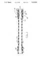
- FIG. 1illustrates a side cutaway view through a defibrillation electrode manufactured according to the present invention
- FIG. 2illustrates an initial step of the manufacture of the electrode illustrated in FIG. 1;
- FIGS. 3 and 4illustrate various points within the process of assembly of the electrode illustrated in FIG. 1.
- FIG. 1is a side cutaway view through an endocardial defibrillation electrode according to the present invention.
- the electrode coil 10is a space wound, single filar coil of platinum mounted around insulative tubing 12. Between the coil 10 and the tubing 12 and between the individual turns of the coil 10 is a filler plastic tube 14 which is preferably insulative, but may be conductive plastic in some cases.
- the filler plastic tube 14extends radially outward from sheath 12 between the individual turns of coil 10 and typically extends outward between the individual turns of coil 10 to a distance of approximately one-third the diameter of the wire from which coil 10 is fabricated.
- Tube 14 and tubing 12are preferably fabricated of an implantable elastic plastic, preferably a polyurethane. Tube 14 and tubing 12 together form the lead body in the vicinity of electrode coil 10.
- coil 10is coupled to a welding sleeve 16 by means of a laser weld at shoulder 18.
- coil 10is coupled to transition sleeve 20 by means of a laser weld at shoulder 22.
- Welding sleeve 16 and transitional sleeve 20are both preferably fabricated of an inert, conductive metal such as platinum to which coil 10 may be readily welded.
- Transitional sleeve 20is provided with two perpendicular bores 24 and a circumferential groove 26.
- Transitional sleeve 20extends proximally into contact with an elongated coiled conductor (not illustrated) extending to the proximal end of the lead.
- This conductorserves to couple defibrillation electrode 10 to an implantable defibrillator and may be manufactured using any conventional technique known to the art and coupled to transitional sleeve 20 using any conventional technique known to the art such as crimping, welding, etc.
- Surrounding the proximal portion of electrode coil 10is an outer insulative sheath 30 which extends proximally to the proximal end of the lead, covering the coil coupled to transitional sleeve 20.
- an outer insulative sheath 32covers the distal end of electrode coil 10 and may extend distally to one or more pacing electrodes coupled to conductors within tubing 12.
- outer insulative sheaths 30 and 32are fabricated of a polyurethane of one of the types typically used in conjunction with cardiac pacing leads and are preferably mechanically coupled to the proximal and distal ends of electrode coil 10 by means of an adhesive to further stabilize their locations.
- FIG. 2illustrates an early step in the manufacture of a defibrillation electrode according to the present invention.
- tube 12is attached to a holding fixture at its proximal end (not illustrated) and filler tube 14 is slid over a stylet 40.
- Stylet 40is provided with a hooked and 42 passed through the distal end of tubing 12.
- tubing 12displays an outer diameter somewhat greater than the inner diameter of filler tube 14.
- tubing 12may be 0.068" ⁇ 0.082" Pellethane® 2363-80A polyurethane
- filler tube 14may be a 0.079" ⁇ 0.095" tube fabricated of the same material.
- Filler tube 14is placed over stylet 40.
- the hooked end of stylet 40is passed through the wall of tubing 12 and used to extend the wall of tubing 12 until the diameter of tubing 12 has decreased sufficiently to slide filler tube 14 over tubing 12.
- tubing 12 and filler tube 14are then allowed to air dry for approximately 1/2 hour, and a urethane adhesive is then backfilled between filler tube 14 and tubing 12 at the proximal and distal ends of filler tubing 14.
- This assemblyis allowed to air dry and is placed in an oven under nigrogen purge.
- the oven temperatureis gradually increased to 150° C. After about five to ten minutes at 150° C., the oven is shut off, and the temperature allowed to fall. This heating step relieves any stresses built up in the tubing.
- the tubingis removed from the oven and allowed to cool to room temperature.
- FIG. 3illustrates a later step in the assembly process.
- the transition sleeve 20has been located adjacent the proximal end of filler tubing 14.
- Electrode coil 10,preferably has an inner diameter less than the outer diameter of the assembly comprising tubing 12 and filler tubing 14.
- Coil 10may be a space wound coil of platinum wire and may have an inner diameter of 0.092".
- Coil 10is placed over stylet 40, and the hooked distal end 42 of stylet 40 is again passed through the distal end of tubing 12.
- Stylet 40is used to stretch tubing 12 and filler tube 14, allowing coil 10 to be slid proximally over filler tube 14 until its proximal end abuts the circumferential shoulder 22 of transition sleeve 20.
- Tubing 12 and tube 14are the allowed to relax and re-expand into contact with the interior of electrode coil 10.
- FIG. 4illustrates a subsequent step in the process of manufacture of the electrode and shows welding sleeve 16 slipped over tubing 12 inside the distal end of electrode coil 10.
- the inner diameter of tubing 12is less than its normal inner diameter as tubing 12 and filler tube 14 are under radial compression by electrode coil 10.
- Teflon coated mandral 44has an outer diameter approximately equal to the inner diameter of tubing 10 in its relaxed, uncompressed state.
- Mandral 44is lubricated with alcohol and slid into the interior of tubing 10 compressing tubing 10 and filler tubing 14 against the interior of coil 10.
- This assemblyis allowed to air dry and is then placed into an oven gradually heated to 150° C. under nitrogen purge in order to cause flow of filler tube 14 between the individual turns of electrode coil 10 to produce the structure illustrated in FIG. 1 above. After about five to ten minutes at 150° C., the oven is turned off and the temperature is allowed to gradually fall.
- the assemblyis then removed from the oven, allowed to cool for at least 30 minutes, and the mandral is removed. Removal of the mandral maybe facilitated by injection of air between the tubing and the mandral. Alternatively, alcohol may be injected between the tubing and the mandral to facilitate removal of the mandral.
- the relative sizes of tubing 12, filler tubing 14 and electrode coil 10should be such that after this baking step, material from filler tube 14 extends radially within the spaces between the individual turns electrode coil 10 a distance of approximately one-third to one-half of the diameter of the wire from which electrode coil 10 is fabricated.
- the remainder of the assembly of the leadtypically follows the completion of this step and would include laser welding of the electrode 10 and two sleeves 16 and 20, coupling of a conductor coil to the proximal end of sleeve 20 and location of outer insulative sheaths 30 and 32 overlapping proximal and distal ends, respectively, of electrode coil 10 as illustrated in FIG. 1.
- Assembly of the remainder of the leadmay also optionally include the provision of one or more pacing electrodes at the distal end of the lead and will include the provision of an electrical connector assembly at the proximal end of the lead. Addition of these assemblies to the lead may be accomplished using any of a number of available prior art structures and manufacturing techniques such as those disclosed in U.S. Pat. No. 4,506,680, U.S. Pat.
Landscapes
- Health & Medical Sciences (AREA)
- Heart & Thoracic Surgery (AREA)
- Vascular Medicine (AREA)
- Cardiology (AREA)
- Engineering & Computer Science (AREA)
- Biomedical Technology (AREA)
- Nuclear Medicine, Radiotherapy & Molecular Imaging (AREA)
- Radiology & Medical Imaging (AREA)
- Life Sciences & Earth Sciences (AREA)
- Animal Behavior & Ethology (AREA)
- General Health & Medical Sciences (AREA)
- Public Health (AREA)
- Veterinary Medicine (AREA)
- Electrotherapy Devices (AREA)
Abstract
Description
This is a divisional of copending application Ser. No. 07/479,928, filed on Feb. 14, 1990, now U.S. Pat. No. 5,042,143.
This invention relates to medical electrical stimulation electrodes in general and to defibrillation electrodes in particular.
In the past years, there has been substantial activity toward development of a practical implantable defibrillator. Most proposals involve the use of large surface area implantable electrodes either to be mounted Within the heart, on the exterior of the heart or subcutaneously. One common approach of providing a large surface area electrode is to employ an elongated exposed coil of biocompatible metal. In the context of an endocardial lead, this is disclosed in U.S. Pat. No. 4,161,952 issued to Kinney. In the context of an epicardial lead, this is disclosed in the context of U.S. Pat. No. 4,187,634 issued to Holleman et al.
In an endocardial lead, an elongated coil serving as the electrode can be mounted around the exterior of an insulative lead body. It is believed desirable in this context to stabilize the electrode coil with respect to the lead body, both to provide mechanical integrity and to prevent fibrous in growth around the individual coils of the electrode coil. In the above cited Kinney et al patent, this is accomplished by sliding the coil over the lead body and backfilling the spaces between the electrode coil with a plastic material. The exterior surface of the electrode is then machined to provide a smooth surface. Alternatively, the backfilling may be removed by means of a plasma etch as disclosed in commonly assigned, co-pending application Ser. No. 07/376,731 by Kiekhafer et al, for a "Method for Fabrication of a Medical Electrode" filed Jul. 7, 1989, now U.S. Pat. No. 4,934,049. In this application, the backfilling is illustrated as extending radially outward between the turns of the coil about one-third to one-half the diameter of the coil wire. This application is incorporated herein by reference in its entirety.
The present invention is directed to producing a pacing lead having a structure similar to that of a structure produced by the method disclosed in the above cited Kiekhafer application but without the necessity of the use of a backfilling step which is time consuming and generally involves a large amount of hand labor. The method of the present invention also allows the use of materials which are not readily applied using a backfilling method.
FIG. 1 illustrates a side cutaway view through a defibrillation electrode manufactured according to the present invention;
FIG. 2 illustrates an initial step of the manufacture of the electrode illustrated in FIG. 1;
FIGS. 3 and 4 illustrate various points within the process of assembly of the electrode illustrated in FIG. 1.
FIG. 1 is a side cutaway view through an endocardial defibrillation electrode according to the present invention. Theelectrode coil 10 is a space wound, single filar coil of platinum mounted aroundinsulative tubing 12. Between thecoil 10 and thetubing 12 and between the individual turns of thecoil 10 is a fillerplastic tube 14 which is preferably insulative, but may be conductive plastic in some cases. The fillerplastic tube 14 extends radially outward fromsheath 12 between the individual turns ofcoil 10 and typically extends outward between the individual turns ofcoil 10 to a distance of approximately one-third the diameter of the wire from whichcoil 10 is fabricated.
At the distal end of the lead, an outerinsulative sheath 32 covers the distal end ofelectrode coil 10 and may extend distally to one or more pacing electrodes coupled to conductors withintubing 12. In the preferred embodiment of the present invention, outerinsulative sheaths electrode coil 10 by means of an adhesive to further stabilize their locations.
FIG. 2 illustrates an early step in the manufacture of a defibrillation electrode according to the present invention. In this early step,tube 12 is attached to a holding fixture at its proximal end (not illustrated) andfiller tube 14 is slid over astylet 40.Stylet 40 is provided with a hooked and 42 passed through the distal end oftubing 12.
Preferablytubing 12 displays an outer diameter somewhat greater than the inner diameter offiller tube 14. For example,tubing 12 may be 0.068"×0.082" Pellethane® 2363-80A polyurethane, andfiller tube 14 may be a 0.079"×0.095" tube fabricated of the same material.
The assembly oftubing 12 andfiller tube 14 is then allowed to air dry for approximately 1/2 hour, and a urethane adhesive is then backfilled betweenfiller tube 14 andtubing 12 at the proximal and distal ends offiller tubing 14.
This assembly is allowed to air dry and is placed in an oven under nigrogen purge. The oven temperature is gradually increased to 150° C. After about five to ten minutes at 150° C., the oven is shut off, and the temperature allowed to fall. This heating step relieves any stresses built up in the tubing. The tubing is removed from the oven and allowed to cool to room temperature.
FIG. 3 illustrates a later step in the assembly process. Prior to this step, thetransition sleeve 20 has been located adjacent the proximal end offiller tubing 14.Electrode coil 10, preferably has an inner diameter less than the outer diameter of theassembly comprising tubing 12 andfiller tubing 14.Coil 10 may be a space wound coil of platinum wire and may have an inner diameter of 0.092".Coil 10 is placed overstylet 40, and the hookeddistal end 42 ofstylet 40 is again passed through the distal end oftubing 12.Stylet 40 is used to stretchtubing 12 andfiller tube 14, allowingcoil 10 to be slid proximally overfiller tube 14 until its proximal end abuts thecircumferential shoulder 22 oftransition sleeve 20.Tubing 12 andtube 14 are the allowed to relax and re-expand into contact with the interior ofelectrode coil 10.
FIG. 4 illustrates a subsequent step in the process of manufacture of the electrode and showswelding sleeve 16 slipped overtubing 12 inside the distal end ofelectrode coil 10. At this point, the inner diameter oftubing 12 is less than its normal inner diameter astubing 12 andfiller tube 14 are under radial compression byelectrode coil 10. Teflon coatedmandral 44 has an outer diameter approximately equal to the inner diameter oftubing 10 in its relaxed, uncompressed state.Mandral 44 is lubricated with alcohol and slid into the interior oftubing 10 compressingtubing 10 andfiller tubing 14 against the interior ofcoil 10. This assembly is allowed to air dry and is then placed into an oven gradually heated to 150° C. under nitrogen purge in order to cause flow offiller tube 14 between the individual turns ofelectrode coil 10 to produce the structure illustrated in FIG. 1 above. After about five to ten minutes at 150° C., the oven is turned off and the temperature is allowed to gradually fall.
The assembly is then removed from the oven, allowed to cool for at least 30 minutes, and the mandral is removed. Removal of the mandral maybe facilitated by injection of air between the tubing and the mandral. Alternatively, alcohol may be injected between the tubing and the mandral to facilitate removal of the mandral.
Preferably, the relative sizes oftubing 12,filler tubing 14 andelectrode coil 10 should be such that after this baking step, material fromfiller tube 14 extends radially within the spaces between the individual turns electrode coil 10 a distance of approximately one-third to one-half of the diameter of the wire from whichelectrode coil 10 is fabricated.
The remainder of the assembly of the lead typically follows the completion of this step and would include laser welding of theelectrode 10 and twosleeves sleeve 20 and location of outerinsulative sheaths electrode coil 10 as illustrated in FIG. 1. Assembly of the remainder of the lead may also optionally include the provision of one or more pacing electrodes at the distal end of the lead and will include the provision of an electrical connector assembly at the proximal end of the lead. Addition of these assemblies to the lead may be accomplished using any of a number of available prior art structures and manufacturing techniques such as those disclosed in U.S. Pat. No. 4,506,680, U.S. Pat. No. 4,502,492, U.S. Pat. No. 4,258,725, U.S. Pat. No. 4,106,512, or U.S. Pat. Application Ser. No. 07/198,540, filed May 25, 1988 by Doan et al for a "Connector For Multiconductor Leads", all of which are incorporated herein by reference. However, it is believed that one of skill in the art would readily appreciate that the present invention can be applied to any elongated medical electrical lead employing any desired combination of additional electrodes, sensors and connectors.
As such, the embodiment illustrated above should be considered exemplary rather than limiting with regard to the scope of the following claims
Claims (4)
1. An implantable electrode lead comprising:
an elongated polyurethane lead body, an elongated space wound electrode coil fabricated from a conductive wire having a cross-sectional diameter, exposed to the exterior of said polyurethane lead body, said polyurethane lead body extending radially outward between individual turns of said electrode coil to a depth of approximately one-third or greater of said diameter of said wire; and
conductor means for coupling said electrode coil to an implantable medical device.
2. A lead according to claim 1 wherein said polyurethane lead body extends radially outward between individual turns of said electrode coil to a depth of approximately one-third to one-half of said diameter of said wire.
3. An implantable electrode lead comprising:
an elongated tubular polyurethane lead body, an elongated space wound electrode coil mounted to the exterior of said polyurethane lead body, wherein said electrode coil is fabricated from a conductive wire having a cross-sectional diameter, said polyurethane lead body extending radially outward between individual turns of said electrode coil to a depth of at least approximately one-third of the diameter of said wire; and
conductor means for coupling said electrode coil to an implantable medical device.
4. A lead according to claim 3 wherein said polyurethane lead body extends radially outward between individual turns of said electrode coil to a depth of approximately one-third to one-half the diameter of said wire.
Priority Applications (1)
| Application Number | Priority Date | Filing Date | Title |
|---|---|---|---|
| US07/639,632US5115818A (en) | 1990-02-14 | 1991-01-10 | Implantable electrode |
Applications Claiming Priority (2)
| Application Number | Priority Date | Filing Date | Title |
|---|---|---|---|
| US07/479,928US5042143A (en) | 1990-02-14 | 1990-02-14 | Method for fabrication of implantable electrode |
| US07/639,632US5115818A (en) | 1990-02-14 | 1991-01-10 | Implantable electrode |
Related Parent Applications (1)
| Application Number | Title | Priority Date | Filing Date |
|---|---|---|---|
| US07/479,928DivisionUS5042143A (en) | 1990-02-14 | 1990-02-14 | Method for fabrication of implantable electrode |
Publications (1)
| Publication Number | Publication Date |
|---|---|
| US5115818Atrue US5115818A (en) | 1992-05-26 |
Family
ID=27046411
Family Applications (1)
| Application Number | Title | Priority Date | Filing Date |
|---|---|---|---|
| US07/639,632Expired - LifetimeUS5115818A (en) | 1990-02-14 | 1991-01-10 | Implantable electrode |
Country Status (1)
| Country | Link |
|---|---|
| US (1) | US5115818A (en) |
Cited By (76)
| Publication number | Priority date | Publication date | Assignee | Title |
|---|---|---|---|---|
| US5342414A (en)* | 1993-07-01 | 1994-08-30 | Medtronic, Inc. | Transvenous defibrillation lead |
| US5439485A (en)* | 1993-09-24 | 1995-08-08 | Ventritex, Inc. | Flexible defibrillation electrode of improved construction |
| US5454839A (en)* | 1992-07-27 | 1995-10-03 | Angeion Corporation | Low profile defibrillation catheter |
| US5466252A (en)* | 1992-10-02 | 1995-11-14 | W. L. Gore & Associates, Inc. | Implantable lead |
| US5599346A (en)* | 1993-11-08 | 1997-02-04 | Zomed International, Inc. | RF treatment system |
| US5609622A (en)* | 1993-02-01 | 1997-03-11 | W. L. Gore & Associates, Inc. | Implantable electrode with conductive polytetrafluoroethylene elecrode |
| US5649974A (en)* | 1992-07-27 | 1997-07-22 | Angeion Corporation | Low profile defibrillation catheter |
| US5676694A (en)* | 1996-06-07 | 1997-10-14 | Medtronic, Inc. | Medical electrical lead |
| US5676662A (en)* | 1995-03-17 | 1997-10-14 | Daig Corporation | Ablation catheter |
| US5755764A (en)* | 1996-09-10 | 1998-05-26 | Sulzer Intermedics Inc. | Implantable cardiac stimulation catheter |
| US5759202A (en)* | 1997-04-28 | 1998-06-02 | Sulzer Intermedics Inc. | Endocardial lead with lateral active fixation |
| US5769881A (en)* | 1997-05-22 | 1998-06-23 | Sulzer Intermedics Inc. | Endocardial lead with multiple branches |
| US5855552A (en)* | 1994-09-21 | 1999-01-05 | Ep Technologies, Inc. | Catheter having ring electrodes secured thereon |
| US5871532A (en)* | 1997-05-22 | 1999-02-16 | Sulzer Intermedics Inc. | Epicardial lead for minimally invasive implantation |
| US5913855A (en) | 1995-08-15 | 1999-06-22 | Rita Medical Systems, Inc. | Multiple antenna ablation apparatus and method |
| US5919222A (en)* | 1998-01-06 | 1999-07-06 | Medtronic Inc. | Adjustable medical electrode lead |
| US5925042A (en) | 1995-08-15 | 1999-07-20 | Rita Medical Systems, Inc. | Multiple antenna ablation apparatus and method |
| US5928229A (en) | 1993-11-08 | 1999-07-27 | Rita Medical Systems, Inc. | Tumor ablation apparatus |
| US5951547A (en) | 1995-08-15 | 1999-09-14 | Rita Medical Systems, Inc. | Multiple antenna ablation apparatus and method |
| US5957970A (en)* | 1998-02-18 | 1999-09-28 | Medtronic, Inc. | Method of fabricating a medical electrical lead |
| US5964793A (en)* | 1996-06-20 | 1999-10-12 | Rutten; Jean | Lead introducer with defibrillation electrode and method of atrial defibrillation |
| US5980517A (en) | 1995-08-15 | 1999-11-09 | Rita Medical Systems, Inc. | Cell necrosis apparatus |
| US6035239A (en)* | 1998-11-10 | 2000-03-07 | Intermedics Inc. | Cardiac lead with reduced inner crimp sleeve |
| US6052625A (en)* | 1998-11-09 | 2000-04-18 | Medtronic, Inc. | Extractable implantable medical lead |
| US6059739A (en)* | 1998-05-29 | 2000-05-09 | Medtronic, Inc. | Method and apparatus for deflecting a catheter or lead |
| US6059780A (en) | 1995-08-15 | 2000-05-09 | Rita Medical Systems, Inc. | Multiple antenna ablation apparatus and method with cooling element |
| US6061595A (en)* | 1999-01-04 | 2000-05-09 | Pacesetter, Inc. | Laser spot weld winding to connector joint |
| WO2000027469A2 (en) | 1998-11-09 | 2000-05-18 | Medtronic, Inc. | Extractable implantable medical lead |
| US6071280A (en) | 1993-11-08 | 2000-06-06 | Rita Medical Systems, Inc. | Multiple electrode ablation apparatus |
| US6080150A (en) | 1995-08-15 | 2000-06-27 | Rita Medical Systems, Inc. | Cell necrosis apparatus |
| US6090105A (en) | 1995-08-15 | 2000-07-18 | Rita Medical Systems, Inc. | Multiple electrode ablation apparatus and method |
| US6132425A (en) | 1995-08-15 | 2000-10-17 | Gough; Edward J. | Cell necrosis apparatus |
| US6141593A (en)* | 1998-11-10 | 2000-10-31 | Intermedics Inc. | Cardiac lead with ETEE coated DBS coil |
| US6146338A (en)* | 1999-04-23 | 2000-11-14 | Medtronic, Inc. | Apparatus for deflecting a catheter or lead |
| US6293594B1 (en) | 1999-01-20 | 2001-09-25 | Pacesetter, Inc. | Joining a winding to a connector using a transition ring |
| US6374142B1 (en) | 2000-02-22 | 2002-04-16 | Cardiac Pacemakers, Inc. | Isodiametric pacing/defibrillation lead |
| US6373024B1 (en)* | 1999-02-17 | 2002-04-16 | Pacesetter, Inc. | Laser-welded joint |
| US6456888B1 (en) | 2000-08-18 | 2002-09-24 | Cardiac Pacemakers, Inc. | Geometry for coupling and electrode to a conductor |
| US20030199952A1 (en)* | 2002-04-22 | 2003-10-23 | Stolz Brian T. | Implantable lead with improved distal tip |
| US20030199950A1 (en)* | 2002-04-22 | 2003-10-23 | Brian Stolz | Implantable lead with isolated contact coupling |
| US20030199953A1 (en)* | 2002-04-22 | 2003-10-23 | Stolz Brian T. | Implantable lead with coplanar contact coupling |
| US6697675B1 (en) | 2001-06-14 | 2004-02-24 | Pacesetter, Inc. | Laser welded joint for implantable lead |
| US6801809B2 (en) | 2000-02-22 | 2004-10-05 | Medtronic, Inc. | Extractable implantable medical lead |
| US20050004642A1 (en)* | 1998-11-09 | 2005-01-06 | Medtronic, Inc. | Implantable medical lead including overlay |
| US20050165452A1 (en)* | 2004-01-28 | 2005-07-28 | Medtronic, Inc. | Antithrombogenic medical device |
| US20050228470A1 (en)* | 2004-04-12 | 2005-10-13 | Osypka Thomas P | Implantable lead having articulated shocking coil |
| US6958062B1 (en) | 1993-11-08 | 2005-10-25 | Rita Medical Systems, Inc. | Multiple antenna ablation apparatus and method |
| US20060241734A1 (en)* | 2005-04-25 | 2006-10-26 | Marshall Mark T | Medical electrical electrodes with conductive polymer |
| US20070142890A1 (en)* | 2005-12-19 | 2007-06-21 | Cardiac Pacemakers, Inc. | Interconnections of implantable lead conductors and electrodes and reinforcement therefor |
| US7239923B1 (en) | 2000-08-01 | 2007-07-03 | Cardiac Pacemakers, Inc. | Lead having varying stiffness and method of manufacturing thereof |
| US20070186515A1 (en)* | 2006-02-16 | 2007-08-16 | Ruetten Roger M | System for monitoring flexible container usage |
| US20070239249A1 (en)* | 2000-08-01 | 2007-10-11 | Cardiac Pacemakers, Inc. | Lead having varying stiffness and method of manufacturing thereof |
| US20080046059A1 (en)* | 2006-08-04 | 2008-02-21 | Zarembo Paul E | Lead including a heat fused or formed lead body |
| US20080057784A1 (en)* | 2006-08-31 | 2008-03-06 | Cardiac Pacemakers, Inc. | Lead assembly including a polymer interconnect and methods related thereto |
| US20080161788A1 (en)* | 2006-12-28 | 2008-07-03 | Dando Jeremy D | Ablation Catheter With Sensor Array And Discrimination Circuit To Minimize Variation In Power Density |
| US20080251966A1 (en)* | 2006-01-12 | 2008-10-16 | Pacesetter, Inc. | Method of making a tubular body for a cathether, sheath or lead |
| WO2009006530A1 (en) | 2007-07-05 | 2009-01-08 | Boston Scientific Neuromodulation Corporation | Lead with contacts formed by coiled conductor and methods of manufacture and use |
| US20100331934A1 (en)* | 2009-06-29 | 2010-12-30 | Boston Scientific Neuromodulation Corporation | Multi-element contact assemblies for electrical stimulation systems and systems and methods of making and using |
| US8442648B2 (en) | 2008-08-15 | 2013-05-14 | Cardiac Pacemakers, Inc. | Implantable medical lead having reduced dimension tubing transition |
| US8734439B2 (en) | 1995-08-15 | 2014-05-27 | Angiodynamics, Inc | Ablation apparatus and method |
| US8751018B1 (en)* | 2007-05-08 | 2014-06-10 | Pacesetter Inc. | Implantable lead and method of making the same |
| US8831749B2 (en) | 2012-10-31 | 2014-09-09 | Medtronic, Inc. | Implantable medical electrical lead conductors and construction methods |
| US9242088B2 (en) | 2013-11-22 | 2016-01-26 | Simon Fraser University | Apparatus and methods for assisted breathing by transvascular nerve stimulation |
| US10039920B1 (en) | 2017-08-02 | 2018-08-07 | Lungpacer Medical, Inc. | Systems and methods for intravascular catheter positioning and/or nerve stimulation |
| US10293164B2 (en) | 2017-05-26 | 2019-05-21 | Lungpacer Medical Inc. | Apparatus and methods for assisted breathing by transvascular nerve stimulation |
| US10391314B2 (en) | 2014-01-21 | 2019-08-27 | Lungpacer Medical Inc. | Systems and related methods for optimization of multi-electrode nerve pacing |
| US10406367B2 (en) | 2012-06-21 | 2019-09-10 | Lungpacer Medical Inc. | Transvascular diaphragm pacing system and methods of use |
| US10512772B2 (en) | 2012-03-05 | 2019-12-24 | Lungpacer Medical Inc. | Transvascular nerve stimulation apparatus and methods |
| US10561843B2 (en) | 2007-01-29 | 2020-02-18 | Lungpacer Medical, Inc. | Transvascular nerve stimulation apparatus and methods |
| US10940308B2 (en) | 2017-08-04 | 2021-03-09 | Lungpacer Medical Inc. | Systems and methods for trans-esophageal sympathetic ganglion recruitment |
| US10987511B2 (en) | 2018-11-08 | 2021-04-27 | Lungpacer Medical Inc. | Stimulation systems and related user interfaces |
| US11173316B2 (en)* | 2015-09-22 | 2021-11-16 | Sorin Crm Sas | Method of manufacturing an implantable defibrillation coil |
| US11357979B2 (en) | 2019-05-16 | 2022-06-14 | Lungpacer Medical Inc. | Systems and methods for sensing and stimulation |
| US11771900B2 (en) | 2019-06-12 | 2023-10-03 | Lungpacer Medical Inc. | Circuitry for medical stimulation systems |
| US11883658B2 (en) | 2017-06-30 | 2024-01-30 | Lungpacer Medical Inc. | Devices and methods for prevention, moderation, and/or treatment of cognitive injury |
| US12029903B2 (en) | 2017-12-11 | 2024-07-09 | Lungpacer Medical Inc. | Systems and methods for strengthening a respiratory muscle |
Citations (5)
| Publication number | Priority date | Publication date | Assignee | Title |
|---|---|---|---|---|
| US4154246A (en)* | 1977-07-25 | 1979-05-15 | Leveen Harry H | Field intensification in radio frequency thermotherapy |
| US4161952A (en)* | 1977-11-01 | 1979-07-24 | Mieczyslaw Mirowski | Wound wire catheter cardioverting electrode |
| US4817634A (en)* | 1987-06-18 | 1989-04-04 | Medtronic, Inc. | Epicardial patch electrode |
| US4860769A (en)* | 1987-11-12 | 1989-08-29 | Thomas J. Fogarty | Implantable defibrillation electrode |
| US4934049A (en)* | 1989-07-07 | 1990-06-19 | Medtronic, Inc. | Method for fabrication of a medical electrode |
- 1991
- 1991-01-10USUS07/639,632patent/US5115818A/ennot_activeExpired - Lifetime
Patent Citations (5)
| Publication number | Priority date | Publication date | Assignee | Title |
|---|---|---|---|---|
| US4154246A (en)* | 1977-07-25 | 1979-05-15 | Leveen Harry H | Field intensification in radio frequency thermotherapy |
| US4161952A (en)* | 1977-11-01 | 1979-07-24 | Mieczyslaw Mirowski | Wound wire catheter cardioverting electrode |
| US4817634A (en)* | 1987-06-18 | 1989-04-04 | Medtronic, Inc. | Epicardial patch electrode |
| US4860769A (en)* | 1987-11-12 | 1989-08-29 | Thomas J. Fogarty | Implantable defibrillation electrode |
| US4934049A (en)* | 1989-07-07 | 1990-06-19 | Medtronic, Inc. | Method for fabrication of a medical electrode |
Cited By (140)
| Publication number | Priority date | Publication date | Assignee | Title |
|---|---|---|---|---|
| US5454839A (en)* | 1992-07-27 | 1995-10-03 | Angeion Corporation | Low profile defibrillation catheter |
| US5649974A (en)* | 1992-07-27 | 1997-07-22 | Angeion Corporation | Low profile defibrillation catheter |
| US5466252A (en)* | 1992-10-02 | 1995-11-14 | W. L. Gore & Associates, Inc. | Implantable lead |
| US5609622A (en)* | 1993-02-01 | 1997-03-11 | W. L. Gore & Associates, Inc. | Implantable electrode with conductive polytetrafluoroethylene elecrode |
| US5342414A (en)* | 1993-07-01 | 1994-08-30 | Medtronic, Inc. | Transvenous defibrillation lead |
| US5542173A (en)* | 1993-09-24 | 1996-08-06 | Ventritex, Inc. | Method of making flexible defibrillation electrode |
| US5439485A (en)* | 1993-09-24 | 1995-08-08 | Ventritex, Inc. | Flexible defibrillation electrode of improved construction |
| US5599345A (en)* | 1993-11-08 | 1997-02-04 | Zomed International, Inc. | RF treatment apparatus |
| US5599346A (en)* | 1993-11-08 | 1997-02-04 | Zomed International, Inc. | RF treatment system |
| US5928229A (en) | 1993-11-08 | 1999-07-27 | Rita Medical Systems, Inc. | Tumor ablation apparatus |
| US20060247616A1 (en)* | 1993-11-08 | 2006-11-02 | Rita Medical Systems, Inc. | Ablation treatment apparatus |
| US6958062B1 (en) | 1993-11-08 | 2005-10-25 | Rita Medical Systems, Inc. | Multiple antenna ablation apparatus and method |
| US20050033279A1 (en)* | 1993-11-08 | 2005-02-10 | Rita Medical Systems, Inc. | RF treatment apparatus |
| US6660002B1 (en) | 1993-11-08 | 2003-12-09 | Rita Medical Systems, Inc. | RF treatment apparatus |
| US6071280A (en) | 1993-11-08 | 2000-06-06 | Rita Medical Systems, Inc. | Multiple electrode ablation apparatus |
| US5935123A (en)* | 1993-11-08 | 1999-08-10 | Rita Medical Systems, Inc. | RF treatment apparatus |
| US5855552A (en)* | 1994-09-21 | 1999-01-05 | Ep Technologies, Inc. | Catheter having ring electrodes secured thereon |
| US5676662A (en)* | 1995-03-17 | 1997-10-14 | Daig Corporation | Ablation catheter |
| US6132425A (en) | 1995-08-15 | 2000-10-17 | Gough; Edward J. | Cell necrosis apparatus |
| US6059780A (en) | 1995-08-15 | 2000-05-09 | Rita Medical Systems, Inc. | Multiple antenna ablation apparatus and method with cooling element |
| US5925042A (en) | 1995-08-15 | 1999-07-20 | Rita Medical Systems, Inc. | Multiple antenna ablation apparatus and method |
| US5951547A (en) | 1995-08-15 | 1999-09-14 | Rita Medical Systems, Inc. | Multiple antenna ablation apparatus and method |
| US8734439B2 (en) | 1995-08-15 | 2014-05-27 | Angiodynamics, Inc | Ablation apparatus and method |
| US6090105A (en) | 1995-08-15 | 2000-07-18 | Rita Medical Systems, Inc. | Multiple electrode ablation apparatus and method |
| US5980517A (en) | 1995-08-15 | 1999-11-09 | Rita Medical Systems, Inc. | Cell necrosis apparatus |
| US6080150A (en) | 1995-08-15 | 2000-06-27 | Rita Medical Systems, Inc. | Cell necrosis apparatus |
| US5913855A (en) | 1995-08-15 | 1999-06-22 | Rita Medical Systems, Inc. | Multiple antenna ablation apparatus and method |
| US5676694A (en)* | 1996-06-07 | 1997-10-14 | Medtronic, Inc. | Medical electrical lead |
| US5964793A (en)* | 1996-06-20 | 1999-10-12 | Rutten; Jean | Lead introducer with defibrillation electrode and method of atrial defibrillation |
| US5755764A (en)* | 1996-09-10 | 1998-05-26 | Sulzer Intermedics Inc. | Implantable cardiac stimulation catheter |
| US5759202A (en)* | 1997-04-28 | 1998-06-02 | Sulzer Intermedics Inc. | Endocardial lead with lateral active fixation |
| US5769881A (en)* | 1997-05-22 | 1998-06-23 | Sulzer Intermedics Inc. | Endocardial lead with multiple branches |
| US5871532A (en)* | 1997-05-22 | 1999-02-16 | Sulzer Intermedics Inc. | Epicardial lead for minimally invasive implantation |
| US5919222A (en)* | 1998-01-06 | 1999-07-06 | Medtronic Inc. | Adjustable medical electrode lead |
| US5957970A (en)* | 1998-02-18 | 1999-09-28 | Medtronic, Inc. | Method of fabricating a medical electrical lead |
| US6059739A (en)* | 1998-05-29 | 2000-05-09 | Medtronic, Inc. | Method and apparatus for deflecting a catheter or lead |
| US20050004642A1 (en)* | 1998-11-09 | 2005-01-06 | Medtronic, Inc. | Implantable medical lead including overlay |
| WO2000027469A2 (en) | 1998-11-09 | 2000-05-18 | Medtronic, Inc. | Extractable implantable medical lead |
| US6052625A (en)* | 1998-11-09 | 2000-04-18 | Medtronic, Inc. | Extractable implantable medical lead |
| US6035239A (en)* | 1998-11-10 | 2000-03-07 | Intermedics Inc. | Cardiac lead with reduced inner crimp sleeve |
| US6141593A (en)* | 1998-11-10 | 2000-10-31 | Intermedics Inc. | Cardiac lead with ETEE coated DBS coil |
| US6061595A (en)* | 1999-01-04 | 2000-05-09 | Pacesetter, Inc. | Laser spot weld winding to connector joint |
| US6293594B1 (en) | 1999-01-20 | 2001-09-25 | Pacesetter, Inc. | Joining a winding to a connector using a transition ring |
| US6373024B1 (en)* | 1999-02-17 | 2002-04-16 | Pacesetter, Inc. | Laser-welded joint |
| US6485440B1 (en) | 1999-04-23 | 2002-11-26 | Medtronic, Inc. | Apparatus for deflecting a catheter or lead |
| US6146338A (en)* | 1999-04-23 | 2000-11-14 | Medtronic, Inc. | Apparatus for deflecting a catheter or lead |
| US6374142B1 (en) | 2000-02-22 | 2002-04-16 | Cardiac Pacemakers, Inc. | Isodiametric pacing/defibrillation lead |
| US6801809B2 (en) | 2000-02-22 | 2004-10-05 | Medtronic, Inc. | Extractable implantable medical lead |
| US7239923B1 (en) | 2000-08-01 | 2007-07-03 | Cardiac Pacemakers, Inc. | Lead having varying stiffness and method of manufacturing thereof |
| US20070239249A1 (en)* | 2000-08-01 | 2007-10-11 | Cardiac Pacemakers, Inc. | Lead having varying stiffness and method of manufacturing thereof |
| US6456888B1 (en) | 2000-08-18 | 2002-09-24 | Cardiac Pacemakers, Inc. | Geometry for coupling and electrode to a conductor |
| US6697675B1 (en) | 2001-06-14 | 2004-02-24 | Pacesetter, Inc. | Laser welded joint for implantable lead |
| US8386055B2 (en) | 2002-04-22 | 2013-02-26 | Medtronic, Inc. | Implantable lead with isolated contact coupling |
| US20030199952A1 (en)* | 2002-04-22 | 2003-10-23 | Stolz Brian T. | Implantable lead with improved distal tip |
| US20040024440A1 (en)* | 2002-04-22 | 2004-02-05 | Cole Mary Lee | Implantable lead with isolated contact coupling |
| US20040019372A1 (en)* | 2002-04-22 | 2004-01-29 | Cole Mary Lee | Implantable lead with coplanar contact coupling |
| US20030199953A1 (en)* | 2002-04-22 | 2003-10-23 | Stolz Brian T. | Implantable lead with coplanar contact coupling |
| US7184840B2 (en) | 2002-04-22 | 2007-02-27 | Medtronic, Inc. | Implantable lead with isolated contact coupling |
| US8504168B2 (en) | 2002-04-22 | 2013-08-06 | Medtronic, Inc. | Implantable lead with coplanar contact coupling |
| US20030199950A1 (en)* | 2002-04-22 | 2003-10-23 | Brian Stolz | Implantable lead with isolated contact coupling |
| US7856707B2 (en) | 2002-04-22 | 2010-12-28 | Medtronic, Inc. | Method for performing a coplanar connection between a conductor and a contact on an implantable lead |
| US8306631B2 (en) | 2002-04-22 | 2012-11-06 | Medtronic, Inc. | Implantable lead with coplanar contact coupling |
| US20110118814A1 (en)* | 2002-04-22 | 2011-05-19 | Medtronic, Inc. | Implantable lead with coplanar contact coupling |
| US20110202118A1 (en)* | 2002-04-22 | 2011-08-18 | Medtronic, Inc. | Implantable lead with isolated contact coupling |
| US8000802B2 (en) | 2002-04-22 | 2011-08-16 | Medtronic, Inc. | Implantable lead with coplanar contact coupling |
| US7953496B2 (en)* | 2002-04-22 | 2011-05-31 | Medtronic, Inc. | Implantable lead with isolated contact coupling |
| US20050165452A1 (en)* | 2004-01-28 | 2005-07-28 | Medtronic, Inc. | Antithrombogenic medical device |
| US7467017B2 (en)* | 2004-04-12 | 2008-12-16 | Oscor, Inc. | Implantable lead having articulated shocking coil |
| US20050228470A1 (en)* | 2004-04-12 | 2005-10-13 | Osypka Thomas P | Implantable lead having articulated shocking coil |
| US20090187236A1 (en)* | 2005-04-25 | 2009-07-23 | Medtronic, Inc. | Medical electrical electrodes with conductive polymer |
| US8831748B2 (en)* | 2005-04-25 | 2014-09-09 | Medtronic, Inc. | Medical electrical electrodes with conductive polymer |
| US7512447B2 (en)* | 2005-04-25 | 2009-03-31 | Medtronic, Inc. | Medical electrical electrodes with conductive polymer |
| US20060241734A1 (en)* | 2005-04-25 | 2006-10-26 | Marshall Mark T | Medical electrical electrodes with conductive polymer |
| US20090222074A1 (en)* | 2005-12-19 | 2009-09-03 | Zarembo Paul E | Interconnections of implantable lead conductors and electrodes and reinforcement therefor |
| US8055354B2 (en) | 2005-12-19 | 2011-11-08 | Cardiac Pacemakers, Inc. | Interconnections of implantable lead conductors and electrodes and reinforcement therefor |
| US20070142890A1 (en)* | 2005-12-19 | 2007-06-21 | Cardiac Pacemakers, Inc. | Interconnections of implantable lead conductors and electrodes and reinforcement therefor |
| US7546165B2 (en) | 2005-12-19 | 2009-06-09 | Cardiac Pacemakers, Inc. | Interconnections of implantable lead conductors and electrodes and reinforcement therefor |
| US7641757B2 (en) | 2006-01-12 | 2010-01-05 | Pacesetter, Inc. | Method of making a tubular body for a catheter, sheath or lead |
| US7824517B2 (en) | 2006-01-12 | 2010-11-02 | Pacesetter, Inc. | Method of making a tubular body for a catheter, sheath or lead |
| US20100059173A1 (en)* | 2006-01-12 | 2010-03-11 | Pacesetter, Inc. | Method of making a tubular body for a catheter, sheath or lead |
| US20080251966A1 (en)* | 2006-01-12 | 2008-10-16 | Pacesetter, Inc. | Method of making a tubular body for a cathether, sheath or lead |
| US20070186515A1 (en)* | 2006-02-16 | 2007-08-16 | Ruetten Roger M | System for monitoring flexible container usage |
| US20080046059A1 (en)* | 2006-08-04 | 2008-02-21 | Zarembo Paul E | Lead including a heat fused or formed lead body |
| US7917229B2 (en) | 2006-08-31 | 2011-03-29 | Cardiac Pacemakers, Inc. | Lead assembly including a polymer interconnect and methods related thereto |
| US8364282B2 (en) | 2006-08-31 | 2013-01-29 | Cardiac Pacemakers, Inc. | Lead assembly including a polymer interconnect and methods related thereto |
| US20080057784A1 (en)* | 2006-08-31 | 2008-03-06 | Cardiac Pacemakers, Inc. | Lead assembly including a polymer interconnect and methods related thereto |
| US8923989B2 (en) | 2006-08-31 | 2014-12-30 | Cardiac Pacemakers, Inc. | Lead assembly including a polymer interconnect and methods related thereto |
| US20110112616A1 (en)* | 2006-08-31 | 2011-05-12 | Zarembo Paul E | Lead assembly including a polymer interconnect and methods related thereto |
| US8738152B2 (en) | 2006-08-31 | 2014-05-27 | Cardiac Pacemakers, Inc. | Lead assembly including a polymer interconnect and methods related thereto |
| US20090076495A2 (en)* | 2006-12-28 | 2009-03-19 | Sjm/Afd | Ablation catheter with sensor array and discrimination circuit to maximize variation in power density |
| US7766907B2 (en) | 2006-12-28 | 2010-08-03 | St. Jude Medical, Atrial Fibrillation Division, Inc. | Ablation catheter with sensor array and discrimination circuit to minimize variation in power density |
| US20080161788A1 (en)* | 2006-12-28 | 2008-07-03 | Dando Jeremy D | Ablation Catheter With Sensor Array And Discrimination Circuit To Minimize Variation In Power Density |
| US11027130B2 (en) | 2007-01-29 | 2021-06-08 | Lungpacer Medical Inc. | Transvascular nerve stimulation apparatus and methods |
| US10561843B2 (en) | 2007-01-29 | 2020-02-18 | Lungpacer Medical, Inc. | Transvascular nerve stimulation apparatus and methods |
| US10864374B2 (en) | 2007-01-29 | 2020-12-15 | Lungpacer Medical Inc. | Transvascular nerve stimulation apparatus and methods |
| US10765867B2 (en) | 2007-01-29 | 2020-09-08 | Lungpacer Medical Inc. | Transvascular nerve stimulation apparatus and methods |
| US12268877B2 (en) | 2007-01-29 | 2025-04-08 | Lungpacer Medical Inc. | Transvascular nerve stimulation apparatus and methods |
| US10792499B2 (en) | 2007-01-29 | 2020-10-06 | Lungpacer Medical Inc. | Transvascular nerve stimulation apparatus and methods |
| US8751018B1 (en)* | 2007-05-08 | 2014-06-10 | Pacesetter Inc. | Implantable lead and method of making the same |
| EP2165341A4 (en)* | 2007-07-05 | 2011-02-23 | Boston Scient Neuromodulation | Lead with contacts formed by coiled conductor and methods of manufacture and use |
| WO2009006530A1 (en) | 2007-07-05 | 2009-01-08 | Boston Scientific Neuromodulation Corporation | Lead with contacts formed by coiled conductor and methods of manufacture and use |
| EP2535081A1 (en)* | 2007-07-05 | 2012-12-19 | Boston Scientific Neuromodulation Corporation | Lead with contacts formed by coiled conductor and methods of manufacture |
| US8565893B2 (en) | 2008-08-15 | 2013-10-22 | Cardiac Pacemakers, Inc. | Implantable medical lead having reduced dimension tubing transition |
| US8442648B2 (en) | 2008-08-15 | 2013-05-14 | Cardiac Pacemakers, Inc. | Implantable medical lead having reduced dimension tubing transition |
| US8406896B2 (en) | 2009-06-29 | 2013-03-26 | Boston Scientific Neuromodulation Corporation | Multi-element contact assemblies for electrical stimulation systems and systems and methods of making and using |
| US20100331934A1 (en)* | 2009-06-29 | 2010-12-30 | Boston Scientific Neuromodulation Corporation | Multi-element contact assemblies for electrical stimulation systems and systems and methods of making and using |
| US11369787B2 (en) | 2012-03-05 | 2022-06-28 | Lungpacer Medical Inc. | Transvascular nerve stimulation apparatus and methods |
| US10512772B2 (en) | 2012-03-05 | 2019-12-24 | Lungpacer Medical Inc. | Transvascular nerve stimulation apparatus and methods |
| US11357985B2 (en) | 2012-06-21 | 2022-06-14 | Lungpacer Medical Inc. | Transvascular diaphragm pacing systems and methods of use |
| US10406367B2 (en) | 2012-06-21 | 2019-09-10 | Lungpacer Medical Inc. | Transvascular diaphragm pacing system and methods of use |
| US10589097B2 (en) | 2012-06-21 | 2020-03-17 | Lungpacer Medical Inc. | Transvascular diaphragm pacing systems and methods of use |
| US10561844B2 (en) | 2012-06-21 | 2020-02-18 | Lungpacer Medical Inc. | Diaphragm pacing systems and methods of use |
| US8831749B2 (en) | 2012-10-31 | 2014-09-09 | Medtronic, Inc. | Implantable medical electrical lead conductors and construction methods |
| US10035017B2 (en) | 2013-11-22 | 2018-07-31 | Lungpacer Medical, Inc. | Apparatus and methods for assisted breathing by transvascular nerve stimulation |
| US9545511B2 (en) | 2013-11-22 | 2017-01-17 | Simon Fraser University | Apparatus and methods for assisted breathing by transvascular nerve stimulation |
| US9242088B2 (en) | 2013-11-22 | 2016-01-26 | Simon Fraser University | Apparatus and methods for assisted breathing by transvascular nerve stimulation |
| US12239838B2 (en) | 2013-11-22 | 2025-03-04 | Lungpacer Medical Inc. | Apparatus and methods for assisted breathing by transvascular nerve stimulation |
| US11707619B2 (en) | 2013-11-22 | 2023-07-25 | Lungpacer Medical Inc. | Apparatus and methods for assisted breathing by transvascular nerve stimulation |
| US9931504B2 (en) | 2013-11-22 | 2018-04-03 | Lungpacer Medical, Inc. | Apparatus and methods for assisted breathing by transvascular nerve stimulation |
| US12172020B2 (en) | 2014-01-21 | 2024-12-24 | Lungpacer Medical Inc. | Systems and related methods for optimization of multi-electrode nerve pacing |
| US10391314B2 (en) | 2014-01-21 | 2019-08-27 | Lungpacer Medical Inc. | Systems and related methods for optimization of multi-electrode nerve pacing |
| US11311730B2 (en) | 2014-01-21 | 2022-04-26 | Lungpacer Medical Inc. | Systems and related methods for optimization of multi-electrode nerve pacing |
| US11173316B2 (en)* | 2015-09-22 | 2021-11-16 | Sorin Crm Sas | Method of manufacturing an implantable defibrillation coil |
| US10293164B2 (en) | 2017-05-26 | 2019-05-21 | Lungpacer Medical Inc. | Apparatus and methods for assisted breathing by transvascular nerve stimulation |
| US12029901B2 (en) | 2017-06-30 | 2024-07-09 | Lungpacer Medical Inc. | Devices and methods for prevention, moderation, and/or treatment of cognitive injury |
| US11883658B2 (en) | 2017-06-30 | 2024-01-30 | Lungpacer Medical Inc. | Devices and methods for prevention, moderation, and/or treatment of cognitive injury |
| US10039920B1 (en) | 2017-08-02 | 2018-08-07 | Lungpacer Medical, Inc. | Systems and methods for intravascular catheter positioning and/or nerve stimulation |
| US12029902B2 (en) | 2017-08-02 | 2024-07-09 | Lungpacer Medical Inc. | Intravascular catheter methods |
| US10195429B1 (en) | 2017-08-02 | 2019-02-05 | Lungpacer Medical Inc. | Systems and methods for intravascular catheter positioning and/or nerve stimulation |
| US10926087B2 (en) | 2017-08-02 | 2021-02-23 | Lungpacer Medical Inc. | Systems and methods for intravascular catheter positioning and/or nerve stimulation |
| US11090489B2 (en) | 2017-08-02 | 2021-08-17 | Lungpacer Medical, Inc. | Systems and methods for intravascular catheter positioning and/or nerve stimulation |
| US11944810B2 (en) | 2017-08-04 | 2024-04-02 | Lungpacer Medical Inc. | Systems and methods for trans-esophageal sympathetic ganglion recruitment |
| US10940308B2 (en) | 2017-08-04 | 2021-03-09 | Lungpacer Medical Inc. | Systems and methods for trans-esophageal sympathetic ganglion recruitment |
| US12029903B2 (en) | 2017-12-11 | 2024-07-09 | Lungpacer Medical Inc. | Systems and methods for strengthening a respiratory muscle |
| US11890462B2 (en) | 2018-11-08 | 2024-02-06 | Lungpacer Medical Inc. | Stimulation systems and related user interfaces |
| US10987511B2 (en) | 2018-11-08 | 2021-04-27 | Lungpacer Medical Inc. | Stimulation systems and related user interfaces |
| US11717673B2 (en) | 2018-11-08 | 2023-08-08 | Lungpacer Medical Inc. | Stimulation systems and related user interfaces |
| US11357979B2 (en) | 2019-05-16 | 2022-06-14 | Lungpacer Medical Inc. | Systems and methods for sensing and stimulation |
| US11771900B2 (en) | 2019-06-12 | 2023-10-03 | Lungpacer Medical Inc. | Circuitry for medical stimulation systems |
| US12403312B2 (en) | 2019-06-12 | 2025-09-02 | Lungpacer Medical Inc. | Circuitry for medical stimulation systems |
Similar Documents
| Publication | Publication Date | Title |
|---|---|---|
| US5115818A (en) | Implantable electrode | |
| US5042143A (en) | Method for fabrication of implantable electrode | |
| US4934049A (en) | Method for fabrication of a medical electrode | |
| US5957970A (en) | Method of fabricating a medical electrical lead | |
| US5133365A (en) | Implantable tapered spiral endocardial lead for use in internal defibrillation | |
| US6505401B1 (en) | Method of making an implantable medical electrical lead | |
| US6256542B1 (en) | Extractable implantable medical lead | |
| US5016808A (en) | Implantable tapered spiral endocardial lead for use in internal defibrillation | |
| US6801809B2 (en) | Extractable implantable medical lead | |
| US5676694A (en) | Medical electrical lead | |
| US4711027A (en) | Implantable lead construction | |
| US5458629A (en) | Implantable lead ring electrode and method of making | |
| US6321123B1 (en) | J-shaped coronary sinus lead | |
| US5007435A (en) | Connector for multiconductor pacing leads | |
| US6456888B1 (en) | Geometry for coupling and electrode to a conductor | |
| US4944088A (en) | Ring electrode for multiconductor pacing leads | |
| US6456890B2 (en) | Lead with polymeric tubular liner for guidewire and stylet insertion | |
| US4922607A (en) | Method of fabrication an in-line, multipolar electrical connector | |
| US8364281B2 (en) | Implantable lead | |
| US4592372A (en) | Pacing/sensing electrode sleeve and method of forming same | |
| US5999858A (en) | Medical electrical lead | |
| US6066166A (en) | Medical electrical lead | |
| US6144870A (en) | Catheter with improved electrodes and method of fabrication | |
| US20070276458A1 (en) | Novel medical device conductor junctions | |
| US6456889B2 (en) | Lead with polymeric tubular liner for guidewire and stylet insertion |
Legal Events
| Date | Code | Title | Description |
|---|---|---|---|
| STCF | Information on status: patent grant | Free format text:PATENTED CASE | |
| FEPP | Fee payment procedure | Free format text:PAYOR NUMBER ASSIGNED (ORIGINAL EVENT CODE: ASPN); ENTITY STATUS OF PATENT OWNER: LARGE ENTITY | |
| FPAY | Fee payment | Year of fee payment:4 | |
| FPAY | Fee payment | Year of fee payment:8 | |
| FPAY | Fee payment | Year of fee payment:12 |