US5115551A - Method for fitting a flexible strip - Google Patents
Method for fitting a flexible stripDownload PDFInfo
- Publication number
- US5115551A US5115551AUS07/763,869US76386991AUS5115551AUS 5115551 AUS5115551 AUS 5115551AUS 76386991 AUS76386991 AUS 76386991AUS 5115551 AUS5115551 AUS 5115551A
- Authority
- US
- United States
- Prior art keywords
- flange
- strip
- curved path
- seal
- final
- Prior art date
- Legal status (The legal status is an assumption and is not a legal conclusion. Google has not performed a legal analysis and makes no representation as to the accuracy of the status listed.)
- Expired - Lifetime
Links
Images


Classifications
- B—PERFORMING OPERATIONS; TRANSPORTING
- B60—VEHICLES IN GENERAL
- B60J—WINDOWS, WINDSCREENS, NON-FIXED ROOFS, DOORS, OR SIMILAR DEVICES FOR VEHICLES; REMOVABLE EXTERNAL PROTECTIVE COVERINGS SPECIALLY ADAPTED FOR VEHICLES
- B60J10/00—Sealing arrangements
- B60J10/45—Assembling sealing arrangements with vehicle parts
- Y—GENERAL TAGGING OF NEW TECHNOLOGICAL DEVELOPMENTS; GENERAL TAGGING OF CROSS-SECTIONAL TECHNOLOGIES SPANNING OVER SEVERAL SECTIONS OF THE IPC; TECHNICAL SUBJECTS COVERED BY FORMER USPC CROSS-REFERENCE ART COLLECTIONS [XRACs] AND DIGESTS
- Y10—TECHNICAL SUBJECTS COVERED BY FORMER USPC
- Y10T—TECHNICAL SUBJECTS COVERED BY FORMER US CLASSIFICATION
- Y10T29/00—Metal working
- Y10T29/49—Method of mechanical manufacture
- Y10T29/49826—Assembling or joining
- Y10T29/49863—Assembling or joining with prestressing of part
- Y10T29/4987—Elastic joining of parts
- Y—GENERAL TAGGING OF NEW TECHNOLOGICAL DEVELOPMENTS; GENERAL TAGGING OF CROSS-SECTIONAL TECHNOLOGIES SPANNING OVER SEVERAL SECTIONS OF THE IPC; TECHNICAL SUBJECTS COVERED BY FORMER USPC CROSS-REFERENCE ART COLLECTIONS [XRACs] AND DIGESTS
- Y10—TECHNICAL SUBJECTS COVERED BY FORMER USPC
- Y10T—TECHNICAL SUBJECTS COVERED BY FORMER US CLASSIFICATION
- Y10T29/00—Metal working
- Y10T29/49—Method of mechanical manufacture
- Y10T29/49826—Assembling or joining
- Y10T29/49863—Assembling or joining with prestressing of part
- Y10T29/49876—Assembling or joining with prestressing of part by snap fit
- Y—GENERAL TAGGING OF NEW TECHNOLOGICAL DEVELOPMENTS; GENERAL TAGGING OF CROSS-SECTIONAL TECHNOLOGIES SPANNING OVER SEVERAL SECTIONS OF THE IPC; TECHNICAL SUBJECTS COVERED BY FORMER USPC CROSS-REFERENCE ART COLLECTIONS [XRACs] AND DIGESTS
- Y10—TECHNICAL SUBJECTS COVERED BY FORMER USPC
- Y10T—TECHNICAL SUBJECTS COVERED BY FORMER US CLASSIFICATION
- Y10T29/00—Metal working
- Y10T29/53—Means to assemble or disassemble
- Y10T29/53657—Means to assemble or disassemble to apply or remove a resilient article [e.g., tube, sleeve, etc.]
- Y—GENERAL TAGGING OF NEW TECHNOLOGICAL DEVELOPMENTS; GENERAL TAGGING OF CROSS-SECTIONAL TECHNOLOGIES SPANNING OVER SEVERAL SECTIONS OF THE IPC; TECHNICAL SUBJECTS COVERED BY FORMER USPC CROSS-REFERENCE ART COLLECTIONS [XRACs] AND DIGESTS
- Y10—TECHNICAL SUBJECTS COVERED BY FORMER USPC
- Y10T—TECHNICAL SUBJECTS COVERED BY FORMER US CLASSIFICATION
- Y10T29/00—Metal working
- Y10T29/53—Means to assemble or disassemble
- Y10T29/53709—Overedge assembling means
- Y10T29/53787—Binding or covering
- Y10T29/53791—Edge binding
Definitions
- the inventionrelates to apparatus and methods for fitting a flexible strip.
- the stripmay be a sealing strip which is required to be fitted around a door or other closable opening on a motor vehicle body.
- apparatusfor use in mounting an elongate resilient channel-shaped strip on to a mounting flange or the like, comprising a portable body, strip drive means carried by the body and arranged to feed the strip longitudinally along a predetermined path which is fixed in relation to the body and the distal part of which is curved and external to the body, and guide means mounted on the body for receiving the initial end of the strip and guiding it along the said distal part of the path external to the body, the guide means comprising a guide finger pivotally mounted on the body and movable between first and second positions such that a guiding part thereof extending transversely to the distal part of the path moves immediately adjacent to that path and is resiliently contacted by the initial end of the strip and guides that end along the distal part of the path so that the strip presents the open mouth of its channel outwardly of the curve for presentation to and eventual mounting on the mounting flange as the body moves along the length of the flange.
- a method of mounting an elongate resilient channel-shaped strip on to a mounting flange or the likecomprising the steps of selecting a length of the strip, feeding the strip longitudinally towards the flange in a direction transverse to the length of the flange, constraining the initial end of the strip to follow a curved path so that the part of the strip immediately following the initial end presents the mouth of the channel to but spaced from the flange, moving the strip bodily towards the flange so that the said immediately following part of the strip embraces the flange but the initial end is clear of the flange, continuing to move the strip longitudinally and at the same time pressing it towards the flange so that the remainder of the strip embraces the flange, mechanically lifting the said immediately following part of the strip, pressing the initial end of the strip into embracing engagement with the flange and immediately adjacent to the final end of the strip on the flange, and then pressing on to the flange the mechanically lifted part of the strip.
- FIG. 1is a side view of the door opening, showing one form of the apparatus in diagrammatic form;
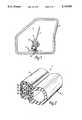
- FIG. 2is an enlarged perspective view of the sealing strip with its end sectioned
- FIG. 3is a cross-section of the sealing strip fitted on to a flange surrounding the openings
- FIG. 4is perspective enlarged view of one form of a robot hand forming part of the apparatus
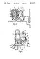
- FIG. 5is a side view of the robot hand of FIG. 4 in the operational state immediately before the strip is placed on to the flange;
- FIG. 6corresponds to FIG. 5 and shows a later operational state
- FIG. 7corresponds to FIG. 6 but shows a following operational state
- FIG. 8corresponds to FIG. 7 but shows a still later operational state
- FIG. 9is a view looking in the direction of the arrow IX of FIG. 4;
- FIG. 10is a partially dismantled view of the robot hand
- FIG. 11is a perspective view corresponding to FIG. 4 but showing a modified form of the robot hand
- FIG. 12shows part of the strip as applied to the door opening:
- FIG. 13is a perspective view of the robot hand of FIG. 11 applying the end of the sealing strip on to the flange;
- FIG. 14corresponds to FIG. 13 but shows a later operational state.
- FIG. 1shows a door opening 5 of a motor vehicle body to which a door seal is to be fitted.
- the door sealcomprises a channel-shaped gripping section 8 which, in use, embracingly grips the flange 6 and supports a soft tubular sealing section 10, so that the seal runs around the door opening, with the sealing section on the outside of the opening.
- FIG. 3when the door, part of which is shown diagramatically at 11, closes onto the opening, it partially-compresses the tubular sealing section 10 so as to form a weather-proof seal.
- the apparatus and method now to be describedare concerned with the automatic fitting of the door seal 7 onto the flange 6.
- the apparatuscomprises two parts: a robot hand 12 as shown in FIG. 1, and a robot arm (not shown), the robot arm supporting the hand 12 by being attached to a fixture 15.
- the fixture 15is best shown in FIG. 4.
- a free end of a length of the seal 7(whose length is sized to fit the periphery of the door opening) is fed into the hand as shown at A in FIG. 1 and the hand automatically grips it and presents the open mouth of the channel of the gripping section 8 towards the flange 6 as shown at B.
- the robot armis programmed to move the hand 12 (under control of robot drive means not shown) towards the flange so that the gripping section grippingly embraces the flange 6 as shown at C. Thereafter, the robot arm moves the robot hand 12 around the periphery of the door opening and at an appropriate distance from the flange 6.
- the handautomatically and continuously feeds the length of door seal onto the flange 6 until the hand has travelled around the complete periphery of the door opening. At the completion of this travel, the distal end of the door seal will be placed in position on the flange immediately adjacent to the initial end.
- the robot armdrives the robot hand 12 around the periphery, it automatically adjusts the angular position of the hand to take account of the corners and bends in the periphery and so that the angle of approach of the seal 7 is appropriate at all positions.
- the gripping section 8is made of plastics or rubber material 16 which is extruded over a channel-shaped metal carrier 18.
- the extruded material 16is extruded to form gripping and sealing lips 20 on the inside facing walls of the channel, and these make gripping and sealing contact with the side surfaces of the flange 6.
- the metal carriermay take any suitable form. For example, it may comprise a series of U-shaped metal elements arranged adjacent to each other to define a channel and either connected together by flexible connecting links or completely disconnected from each other. Instead, however, it may comprise wire looped to and fro and extending along the length of the channel. However, other forms of carrier can be used instead.
- the gripping sectionmay incorporate a substantially inextensible tape or thread 22.
- the robot hand 12comprises a seal drive section 24 containing three pairs of rollers (to be described below) which grip the sides of the seal and are driven so as to feed the seal longitudinally through the hand. These rollers are driven by a main motor 26 via a reduction gearbox 28.
- the drive shaft from the latterpasses through a lid 30 to a belt driving section 32 which distributes the drive from the gearbox output shaft via a drive belt, to the three pairs of rollers in the seal drive section 24.
- the drive shafts from the belt driving section 32 to the pairs of drive rollers in the seal drive section 24are supported in bearings in a bearing section 34.
- a tachogenerator 36monitors the speed of the motor 26.
- the sealenters the seal drive section 24 at A and emerges at the opposite end of the section.
- guide finger 40Ais positioned.
- Guide finger 40Ais pivotally mounted on an arm 42 extending from the body of the seal drive section 24. The locus of the guide finger 40A is shown by the dotted line D. Initially, the guide finger 40A is positioned so that it is adjacent to the point where the seal emerges.
- the purpose of the right-angled finger 40Ais to guide the initial end of the seal 7 in a curved path as it emerges from the robot hand. As shown in FIG. 5, the emerging initial end 7A of the seal 7 contacts the finger 40A. As the seal continues to emerge, it is forced to follow a curved path defined by the locus of the guide finger 40A as it rotates about its pivot point on the arm 42. The seal is held in contact with the guide finger 40A by its own resilience. This process continues until the guide finger 40A reaches the position shown in FIG. 6, the seal following a substantially circular path and in contact with a roller 44.
- the robot armnow moves the robot hand 12 closer towards the flange 6 and the guide roller 44 presses the gripping section 8 on to the flange as shown in FIG. 7.
- the guide finger 40Ais thereafter accelerated away from the end of the seal, this being carried out by means of a motor 46, a gear box 48 and a belt 50, as shown in FIG. 9.
- the robot armthen commences to drive hand 12 around the periphery of the door opening.
- the seal driving section 24drives the seal through the hand at an appropriate rate, and the gripping section is thus laid firmly onto the flange by being guided and pressed on to the flange by the roller 44.
- the distal end of the sealwill pass through the seal drive section 24 and will be laid onto the flange 6 adjacent to the initial end.
- the motor 46(FIG. 4) is then energised so as to return the guide finger 40 to its initial position ready to receive a length of seal for the next door opening.
- FIG. 9shows a view of the underside of the robot hand 12, looking in the direction of the arrow IX in FIG. 4, and with a base 51 removed.
- This Figureshows the three pairs of rollers 52,54 and 56 between which the seal 7 is gripped and driven longitudinally through the unit 12 as the rollers rotate.
- the base 51is formed with raised guide portions 58 so as to guide the seal 7 successively from one pair of rollers to the next on initial pick-up.
- FIG. 10shows a view of the robot hand 12 with the motor 26, the gearbox 28 and the lid 30 removed.
- a main drive roller 60is driven by the output shaft of the gearbox 28 and frictionally drives a continuous drive belt 62.
- Drive belt 62passes successively around the drive rollers 64,66,68,70 and 72. In addition, it passes around a spring-loaded belt tensioner 74.
- drive rollers 64 and 66rotate the pair of seal drive rollers 52 in the seal drive section 24, drive rollers 68 and 72 respectively drive the seal drive rollers of the pair 54, and roller 70 drives one of the pair of seal drive rollers 56, the other one thereof being freely rotatable.
- the speed of the seal drive rollers 50, 52 and 54is such, in relation to the angular movement of the robot arm, that the seal 7 is slightly compressed, lengthwise, as it is laid on the flange 6.
- Thishelps to offset the stretching effect which might otherwise occur and which would have the undesirable effect of laying the door seal partially under tension. If it were laid under tension, it would gradually resile over a period of time and this would have the effect that the two ends of the seal would part, leaving an unsightly gap and with defective weather sealing. This is avoided by laying the seal slightly compressed.
- the nominal length of the sealis predetermined taking this compression into account, so that the ends of the seal are fitted in contact each other.
- the length of sealis supported in any suitable way, for example on the robot hand or the robot arm, during the fitting process.
- the belt 50, and other moving parts of the robot handwould in practice be enclosed within protective coverings.
- FIG. 10shows a modified form of the robot hand of FIG. 4.
- the robot hand of FIG. 10is identical with that of FIG. 4 except for the addition of a plunger 90 which is attached to a piston slidable within a pneumatically or hydraulically controlled cylinder assembly 92.
- the plunger 90can be caused to extend away from the cylinder 92 or to retract towards it by means of pneumatic or hydraulic supply lines 94 and 96.
- the cylinder assembly 92is fixed to the side of the drive section 24 by means not shown.
- the plunger 90is initially completely retracted into the cylinder 92.
- the seal 7then emerges from the robot hand 12 and is guided round the roller 44 by the guide finger 40A, all as described above in FIGS. 5 to 8.
- the plunger 90plays no part and, because it is fully retracted, is clear of the seal and the guide finger 40A.
- the robot handthen places the seal on the flange and travels around the flange in the manner already described, placing the seal on the flange.
- the handwill have travelled completely around the door opening and will have laid the final end 7B of the seal on the flange as shown in FIG. 12.
- the final end 7Bis of course laid adjacent to the initial end 7A.
- the initial end 7A and the immediately adjacent part of the sealare clear of the flange because of the manner in which the robot hand applies the seal to the flange, see FIGS. 7 and 8).
- the robot hand 12then approaches the initial end 7A again, and at the same time the guide finger 40A is partially rotated by its drive motor 46 to the position shown in FIG. 13 so that the guide finger passes between the end 7A of the seal and the flange 6, with the roller 44 engaging the outside surface of the gripping section 8.
- the robot handmoves slightly away from the flange 6 as shown in FIG. 14, to pull the seal away from the flange, and plunger 90 is caused to extend from the cylinder 92 so that it engages the initial end 7A of the seal and presses it on the flange immediately adjacent to the final end 7B.
- Plunger 46is then retracted, the seal retaining itself on the flange by the gripping action of the gripping section.
- the robot handis then moved a short distance in a direction perpendicular to the flange 6, in the direction of the arrow X (FIG. 14) to bring the guide finger 40A clear of the seal.
- the robot handcan also move slightly in a direction parallel to the flange (in the direction of arrow Y) to bring the roller 44 clear of the gripping section.
- the guide finger 40Ais then rotated by the motor 46 into the position shown in FIG. 8.
- the robot handis moved back into the position in which the roller 44 engages the gripping section 8 and then moves to and fro parallel to the flange so as to press the initial end 7A of the seal into complete engagement with the flange so that the two ends of the seal abut each other.
- the sealing stripshould advantageously be slightly compressible lengthwise and should have a length which is slightly greater than the peripheral length of the flange.
Landscapes
- Engineering & Computer Science (AREA)
- Mechanical Engineering (AREA)
- Automatic Assembly (AREA)
- Seal Device For Vehicle (AREA)
- Automobile Manufacture Line, Endless Track Vehicle, Trailer (AREA)
Abstract
Description
Claims (1)
Applications Claiming Priority (2)
| Application Number | Priority Date | Filing Date | Title |
|---|---|---|---|
| GB8920133 | 1989-09-06 | ||
| GB898920133AGB8920133D0 (en) | 1988-12-20 | 1989-09-06 | Apparatus and method for fitting a flexible strip |
Related Parent Applications (1)
| Application Number | Title | Priority Date | Filing Date |
|---|---|---|---|
| US07661462Continuation | 1991-02-26 |
Publications (1)
| Publication Number | Publication Date |
|---|---|
| US5115551Atrue US5115551A (en) | 1992-05-26 |
Family
ID=10662617
Family Applications (2)
| Application Number | Title | Priority Date | Filing Date |
|---|---|---|---|
| US07/460,285Expired - LifetimeUS5031293A (en) | 1989-09-06 | 1990-01-03 | Apparatus for fitting a flexible strip |
| US07/763,869Expired - LifetimeUS5115551A (en) | 1989-09-06 | 1991-09-20 | Method for fitting a flexible strip |
Family Applications Before (1)
| Application Number | Title | Priority Date | Filing Date |
|---|---|---|---|
| US07/460,285Expired - LifetimeUS5031293A (en) | 1989-09-06 | 1990-01-03 | Apparatus for fitting a flexible strip |
Country Status (1)
| Country | Link |
|---|---|
| US (2) | US5031293A (en) |
Cited By (9)
| Publication number | Priority date | Publication date | Assignee | Title |
|---|---|---|---|---|
| US5179774A (en)* | 1990-05-24 | 1993-01-19 | Ford Motor Company | Apparatus and method for mechanically applying a sealing strip |
| US5358397A (en)* | 1993-05-10 | 1994-10-25 | L&L Products, Inc. | Apparatus for extruding flowable materials |
| US5864933A (en)* | 1997-03-21 | 1999-02-02 | Cooper Tire & Rubber Company | Flexible molding application tool |
| US5875670A (en)* | 1996-07-31 | 1999-03-02 | The Standard Products Company | Tool for roll crimping a flange cover |
| US20020090386A1 (en)* | 1998-05-04 | 2002-07-11 | Haslwanter Joseph A. | Skin barrier composition |
| US20040016099A1 (en)* | 2002-07-25 | 2004-01-29 | Hicks Thomas S. | Apparatus and method for attaching a seal to an encapsulated window assembly |
| US20060185166A1 (en)* | 2005-02-24 | 2006-08-24 | General Electric Company | Automated seal strip assembly method and apparatus for rotary machines |
| US20100101151A1 (en)* | 2008-10-23 | 2010-04-29 | Toyota Motor Engineering & Manufacturing North America, Inc. | Weather strip installation device |
| DE102018202375B3 (en) | 2018-02-16 | 2019-02-21 | Thyssenkrupp Ag | Method for interconnecting two sealing end faces of a sealing profile and device |
Families Citing this family (13)
| Publication number | Priority date | Publication date | Assignee | Title |
|---|---|---|---|---|
| US5237730A (en)* | 1988-12-20 | 1993-08-24 | Draftex Industries Limited | Apparatus and method for fitting a flexible strip around a vehicle door opening |
| US5129134A (en)* | 1989-02-01 | 1992-07-14 | General Motors Corporation | Holding arm fixture for use in conjunction with a robot for installing weather stripping in a door or like opening |
| GB2229702B (en)* | 1989-02-04 | 1992-09-30 | Draftex Ind Ltd | Strip handling apparatus |
| GB2244302B (en)* | 1990-05-24 | 1994-01-19 | Ford Motor Co | Applying weather strips |
| US5103547A (en)* | 1991-03-01 | 1992-04-14 | Emco Specialties, Inc. | Apparatus and method for placing weather stripping in a channel |
| FR2681274B1 (en)* | 1991-09-18 | 1993-12-03 | Mesnel Ets | DEVICE FOR THE PLACEMENT OF A U-SECTION PROFILE ON A SIDE OF A FRAME OF AN AUTOMOBILE BODY. |
| FR2699846B1 (en)* | 1992-12-24 | 1995-02-10 | Christophe Boiteux | Articulated wedging element. |
| US5291687A (en)* | 1993-02-04 | 1994-03-08 | Alex Abad | Window track debris accumulation prevention system |
| US6311378B1 (en) | 2000-02-16 | 2001-11-06 | Saargummi Americas, Inc. | Crimp on flange tool for doorseals |
| US6832428B2 (en)* | 2000-04-04 | 2004-12-21 | Honda Giken Kogyo Kabushiki Kaisha | Tool and process for press-fitting a weather strip |
| WO2007057978A1 (en)* | 2005-11-16 | 2007-05-24 | Honda Motor Co., Ltd. | Method and device for mounting soft member |
| CN103935422B (en)* | 2014-04-29 | 2016-04-13 | 神龙汽车有限公司 | The instrument of fast-mounting doorframe sealing band |
| DE102020118940A1 (en)* | 2020-07-17 | 2022-01-20 | Aytec Automation Gmbh | Device for applying a rubber profile |
Citations (6)
| Publication number | Priority date | Publication date | Assignee | Title |
|---|---|---|---|---|
| US4620354A (en)* | 1985-05-28 | 1986-11-04 | General Motors Corporation | Method of applying weatherstrip to a vehicle body opening |
| US4653166A (en)* | 1984-01-11 | 1987-03-31 | Draftex Industries Limited | Apparatus for assembling finishing and sealing strips |
| DE3541865A1 (en)* | 1985-11-27 | 1987-06-04 | Volkswagen Ag | Device for automatically fitting an elongated material onto a flange |
| JPH0218182A (en)* | 1988-07-05 | 1990-01-22 | Honda Motor Co Ltd | Automotive parts mounting equipment |
| US4902549A (en)* | 1987-11-26 | 1990-02-20 | Draftex Industries Limited | Sealing and trimming strips |
| US4996756A (en)* | 1988-02-10 | 1991-03-05 | Draftex Industries Limited | Apparatus for fitting sealing and trimming strips |
Family Cites Families (11)
| Publication number | Priority date | Publication date | Assignee | Title |
|---|---|---|---|---|
| NL7801875A (en)* | 1977-02-24 | 1978-08-28 | Yoshida Kogyo Kk | DEVICE FOR APPLYING A GASKET. |
| JPS5817909Y2 (en)* | 1977-05-04 | 1983-04-11 | ワイケイケイ株式会社 | Gasket installation jig |
| IE48952B1 (en)* | 1978-10-13 | 1985-06-26 | Schlegel Uk Ltd | Method and apparatus for inserting weatherstrip or the like in a groove |
| GB2039974A (en)* | 1978-12-13 | 1980-08-20 | Caunter & Co Ltd | Machine for insertion of weatherstrip into a groove |
| DE3243214A1 (en)* | 1982-11-23 | 1984-08-02 | Knaust, Klaus, 8740 Bad Neustadt | DEVICE FOR AUTOMATICALLY PULLING A SEALING STRIP INTO A GROOVE IN A FRAME |
| DE3661468D1 (en)* | 1985-09-30 | 1989-01-26 | Siemens Ag | Device for inserting sealing strips |
| US4780943A (en)* | 1986-07-18 | 1988-11-01 | General Motors Corporation | Apparatus and method of a robot for installing weather stripping in a door or like opening |
| US4715110A (en)* | 1986-07-18 | 1987-12-29 | General Motors Corporation | Apparatus of a robot for installing weather stripping in a door or like opening |
| US4760636A (en)* | 1986-07-18 | 1988-08-02 | General Motors Corporation | Apparatus of a robot for installing weather stripping in a door or like opening |
| US4747197A (en)* | 1987-03-30 | 1988-05-31 | Charron Eli A | Machine for applying T-molding |
| US4738562A (en)* | 1987-05-15 | 1988-04-19 | Jmk International, Inc. | Apparatus for inserting backing rod into concrete expansion joints |
- 1990
- 1990-01-03USUS07/460,285patent/US5031293A/ennot_activeExpired - Lifetime
- 1991
- 1991-09-20USUS07/763,869patent/US5115551A/ennot_activeExpired - Lifetime
Patent Citations (6)
| Publication number | Priority date | Publication date | Assignee | Title |
|---|---|---|---|---|
| US4653166A (en)* | 1984-01-11 | 1987-03-31 | Draftex Industries Limited | Apparatus for assembling finishing and sealing strips |
| US4620354A (en)* | 1985-05-28 | 1986-11-04 | General Motors Corporation | Method of applying weatherstrip to a vehicle body opening |
| DE3541865A1 (en)* | 1985-11-27 | 1987-06-04 | Volkswagen Ag | Device for automatically fitting an elongated material onto a flange |
| US4902549A (en)* | 1987-11-26 | 1990-02-20 | Draftex Industries Limited | Sealing and trimming strips |
| US4996756A (en)* | 1988-02-10 | 1991-03-05 | Draftex Industries Limited | Apparatus for fitting sealing and trimming strips |
| JPH0218182A (en)* | 1988-07-05 | 1990-01-22 | Honda Motor Co Ltd | Automotive parts mounting equipment |
Cited By (13)
| Publication number | Priority date | Publication date | Assignee | Title |
|---|---|---|---|---|
| US5179774A (en)* | 1990-05-24 | 1993-01-19 | Ford Motor Company | Apparatus and method for mechanically applying a sealing strip |
| US5358397A (en)* | 1993-05-10 | 1994-10-25 | L&L Products, Inc. | Apparatus for extruding flowable materials |
| US5875670A (en)* | 1996-07-31 | 1999-03-02 | The Standard Products Company | Tool for roll crimping a flange cover |
| US5864933A (en)* | 1997-03-21 | 1999-02-02 | Cooper Tire & Rubber Company | Flexible molding application tool |
| US20020090386A1 (en)* | 1998-05-04 | 2002-07-11 | Haslwanter Joseph A. | Skin barrier composition |
| US6874218B2 (en)* | 2002-07-25 | 2005-04-05 | Pilkington North America, Inc. | Apparatus and method for attaching a seal to an encapsulated window assembly |
| US20040016099A1 (en)* | 2002-07-25 | 2004-01-29 | Hicks Thomas S. | Apparatus and method for attaching a seal to an encapsulated window assembly |
| US20050132564A1 (en)* | 2002-07-25 | 2005-06-23 | Hicks Thomas S. | Apparatus for attaching a seal to an encapsulated window assembly |
| US20060185166A1 (en)* | 2005-02-24 | 2006-08-24 | General Electric Company | Automated seal strip assembly method and apparatus for rotary machines |
| US7155800B2 (en)* | 2005-02-24 | 2007-01-02 | General Electric Company | Automated seal strip assembly method and apparatus for rotary machines |
| US20100101151A1 (en)* | 2008-10-23 | 2010-04-29 | Toyota Motor Engineering & Manufacturing North America, Inc. | Weather strip installation device |
| US8322005B2 (en)* | 2008-10-23 | 2012-12-04 | Pow Specialty Equipment Inc. | Weather strip installation device |
| DE102018202375B3 (en) | 2018-02-16 | 2019-02-21 | Thyssenkrupp Ag | Method for interconnecting two sealing end faces of a sealing profile and device |
Also Published As
| Publication number | Publication date |
|---|---|
| US5031293A (en) | 1991-07-16 |
Similar Documents
| Publication | Publication Date | Title |
|---|---|---|
| US5115551A (en) | Method for fitting a flexible strip | |
| CA2004418C (en) | Apparatus and method for fitting a flexible strip | |
| US5048170A (en) | Apparatus for fitting flexible strips | |
| US4760636A (en) | Apparatus of a robot for installing weather stripping in a door or like opening | |
| EP0497048B1 (en) | Apparatus and method for fitting a flexible strip | |
| US4715110A (en) | Apparatus of a robot for installing weather stripping in a door or like opening | |
| US4843701A (en) | Apparatus of a robot for installing weather stripping in a door or like opening | |
| JPH01228779A (en) | Sealing or finishing band fixture | |
| SI0638408T1 (en) | Method and apparatus for making a window panel with a frame of polymeric material | |
| ES2027084A6 (en) | Strip handling apparatus and method | |
| US4502911A (en) | Strapping machine | |
| US5237730A (en) | Apparatus and method for fitting a flexible strip around a vehicle door opening | |
| EP1115589B1 (en) | Strip fitting tool and method of fitting a channel shaped strip | |
| US5155890A (en) | Apparatus and method for fitting a flexible strip | |
| AU546650B2 (en) | Tape drive door operator | |
| US4897913A (en) | Method of using a robot for installing weather stripping in a door or like opening | |
| US5020278A (en) | Apparatus and method of a robot for installing weather stripping in a door or like opening and vehicle produced thereof | |
| US20050193544A1 (en) | Weatherstrip applicator head | |
| NO954034D0 (en) | Machine for continuous stretching of a transmission line for an electric overhead line | |
| EP1007273B1 (en) | Strip fitting tools and methods | |
| US4035868A (en) | Means for handling hides during and after hide-pulling operation | |
| WO2004108459A1 (en) | Method for applying a weatherstrip | |
| CN108773004B (en) | Automatic rubber coating equipment for pull-wire type C-shaped substrate workpiece | |
| CN222310988U (en) | Ribbon cutting device | |
| AU3248595A (en) | Winding device and method |
Legal Events
| Date | Code | Title | Description |
|---|---|---|---|
| STCF | Information on status: patent grant | Free format text:PATENTED CASE | |
| FPAY | Fee payment | Year of fee payment:4 | |
| REMI | Maintenance fee reminder mailed | ||
| FPAY | Fee payment | Year of fee payment:8 | |
| SULP | Surcharge for late payment | ||
| AS | Assignment | Owner name:BANKERS TRUST COMPANY, NEW YORK Free format text:SECURITY AGREEMENT;ASSIGNOR:GENCORP PROPERTY INC.;REEL/FRAME:011425/0810 Effective date:20001228 | |
| AS | Assignment | Owner name:GENCORP PROPERTY INC., CALIFORNIA Free format text:ASSIGNMENT OF ASSIGNORS INTEREST;ASSIGNOR:DRAFTEX INDUSTRIES LIMITED;REEL/FRAME:011675/0705 Effective date:20010227 | |
| AS | Assignment | Owner name:DEUTSCHE BANK TRUST COMPANY AMERICAS, (FORMERLY KN Free format text:CORRECTIVE SECURITY INTEREST TO CORRECT TYPO IN BRIEF AND TO ADD 4 PATENT NUMBERS PREVIOUSLY OMITTED. DOCUMENT PREVIOUSLY RECORDED AT REEL 013386 FRAME 0970.;ASSIGNOR:GENCORP PROPERTY INC.;REEL/FRAME:013782/0216 Effective date:20021002 Owner name:DEUTSCHE BANK TRUST COMPANY AMERICAS, (FORMERLY KN Free format text:ASSIGNMENT OF SECURITY INTEREST IN US TRADEMAKRS A;ASSIGNOR:GENCORP PROPERTY INC.;REEL/FRAME:013386/0970 Effective date:20021002 | |
| FPAY | Fee payment | Year of fee payment:12 | |
| AS | Assignment | Owner name:GDX NORTH AMERICA, INC., NEW YORK Free format text:ASSIGNMENT OF ASSIGNORS INTEREST;ASSIGNOR:GENCORP PROPERTY INC.;REEL/FRAME:015127/0424 Effective date:20040831 | |
| AS | Assignment | Owner name:GDX NORTH AMERICA INC., NEW YORK Free format text:CORRECTIVE ASSIGNMENT TO CORRECT RECEIVING PARTY. PREVIOUSLY RECORDED AT REEL 015127 FRAME 0424;ASSIGNOR:GENCORP PROPERTY INC.;REEL/FRAME:015259/0313 Effective date:20040910 | |
| AS | Assignment | Owner name:KOMAGATA HOLDING B.V., NETHERLANDS Free format text:SECURITY AGREEMENT;ASSIGNOR:GDX NORTH AMERICA, INC.;REEL/FRAME:018837/0277 Effective date:20070118 |