US5114568A - Reclamation system for contaminated material - Google Patents
Reclamation system for contaminated materialDownload PDFInfo
- Publication number
- US5114568A US5114568AUS07/553,536US55353690AUS5114568AUS 5114568 AUS5114568 AUS 5114568AUS 55353690 AUS55353690 AUS 55353690AUS 5114568 AUS5114568 AUS 5114568A
- Authority
- US
- United States
- Prior art keywords
- slurry
- vortex
- soil
- separation chamber
- gas
- Prior art date
- Legal status (The legal status is an assumption and is not a legal conclusion. Google has not performed a legal analysis and makes no representation as to the accuracy of the status listed.)
- Expired - Fee Related
Links
Images

Classifications
- B—PERFORMING OPERATIONS; TRANSPORTING
- B03—SEPARATION OF SOLID MATERIALS USING LIQUIDS OR USING PNEUMATIC TABLES OR JIGS; MAGNETIC OR ELECTROSTATIC SEPARATION OF SOLID MATERIALS FROM SOLID MATERIALS OR FLUIDS; SEPARATION BY HIGH-VOLTAGE ELECTRIC FIELDS
- B03D—FLOTATION; DIFFERENTIAL SEDIMENTATION
- B03D1/00—Flotation
- B03D1/14—Flotation machines
- B03D1/1418—Flotation machines using centrifugal forces
- B03D1/1425—Flotation machines using centrifugal forces air-sparged hydrocyclones
- B—PERFORMING OPERATIONS; TRANSPORTING
- B01—PHYSICAL OR CHEMICAL PROCESSES OR APPARATUS IN GENERAL
- B01D—SEPARATION
- B01D17/00—Separation of liquids, not provided for elsewhere, e.g. by thermal diffusion
- B—PERFORMING OPERATIONS; TRANSPORTING
- B01—PHYSICAL OR CHEMICAL PROCESSES OR APPARATUS IN GENERAL
- B01D—SEPARATION
- B01D17/00—Separation of liquids, not provided for elsewhere, e.g. by thermal diffusion
- B01D17/02—Separation of non-miscible liquids
- B01D17/0205—Separation of non-miscible liquids by gas bubbles or moving solids
- B—PERFORMING OPERATIONS; TRANSPORTING
- B01—PHYSICAL OR CHEMICAL PROCESSES OR APPARATUS IN GENERAL
- B01D—SEPARATION
- B01D17/00—Separation of liquids, not provided for elsewhere, e.g. by thermal diffusion
- B01D17/02—Separation of non-miscible liquids
- B01D17/0217—Separation of non-miscible liquids by centrifugal force
- B—PERFORMING OPERATIONS; TRANSPORTING
- B01—PHYSICAL OR CHEMICAL PROCESSES OR APPARATUS IN GENERAL
- B01D—SEPARATION
- B01D21/00—Separation of suspended solid particles from liquids by sedimentation
- B01D21/26—Separation of sediment aided by centrifugal force or centripetal force
- B01D21/267—Separation of sediment aided by centrifugal force or centripetal force by using a cyclone
- B—PERFORMING OPERATIONS; TRANSPORTING
- B03—SEPARATION OF SOLID MATERIALS USING LIQUIDS OR USING PNEUMATIC TABLES OR JIGS; MAGNETIC OR ELECTROSTATIC SEPARATION OF SOLID MATERIALS FROM SOLID MATERIALS OR FLUIDS; SEPARATION BY HIGH-VOLTAGE ELECTRIC FIELDS
- B03D—FLOTATION; DIFFERENTIAL SEDIMENTATION
- B03D1/00—Flotation
- B03D1/14—Flotation machines
- B03D1/1443—Feed or discharge mechanisms for flotation tanks
- B03D1/1462—Discharge mechanisms for the froth
- B—PERFORMING OPERATIONS; TRANSPORTING
- B03—SEPARATION OF SOLID MATERIALS USING LIQUIDS OR USING PNEUMATIC TABLES OR JIGS; MAGNETIC OR ELECTROSTATIC SEPARATION OF SOLID MATERIALS FROM SOLID MATERIALS OR FLUIDS; SEPARATION BY HIGH-VOLTAGE ELECTRIC FIELDS
- B03D—FLOTATION; DIFFERENTIAL SEDIMENTATION
- B03D1/00—Flotation
- B03D1/14—Flotation machines
- B03D1/1443—Feed or discharge mechanisms for flotation tanks
- B03D1/1468—Discharge mechanisms for the sediments
- B—PERFORMING OPERATIONS; TRANSPORTING
- B03—SEPARATION OF SOLID MATERIALS USING LIQUIDS OR USING PNEUMATIC TABLES OR JIGS; MAGNETIC OR ELECTROSTATIC SEPARATION OF SOLID MATERIALS FROM SOLID MATERIALS OR FLUIDS; SEPARATION BY HIGH-VOLTAGE ELECTRIC FIELDS
- B03D—FLOTATION; DIFFERENTIAL SEDIMENTATION
- B03D1/00—Flotation
- B03D1/14—Flotation machines
- B03D1/16—Flotation machines with impellers; Subaeration machines
- B—PERFORMING OPERATIONS; TRANSPORTING
- B09—DISPOSAL OF SOLID WASTE; RECLAMATION OF CONTAMINATED SOIL
- B09C—RECLAMATION OF CONTAMINATED SOIL
- B09C1/00—Reclamation of contaminated soil
- B09C1/02—Extraction using liquids, e.g. washing, leaching, flotation
- B—PERFORMING OPERATIONS; TRANSPORTING
- B01—PHYSICAL OR CHEMICAL PROCESSES OR APPARATUS IN GENERAL
- B01D—SEPARATION
- B01D2221/00—Applications of separation devices
- B01D2221/04—Separation devices for treating liquids from earth drilling, mining
- B—PERFORMING OPERATIONS; TRANSPORTING
- B01—PHYSICAL OR CHEMICAL PROCESSES OR APPARATUS IN GENERAL
- B01D—SEPARATION
- B01D2221/00—Applications of separation devices
- B01D2221/08—Mobile separation devices
- B—PERFORMING OPERATIONS; TRANSPORTING
- B03—SEPARATION OF SOLID MATERIALS USING LIQUIDS OR USING PNEUMATIC TABLES OR JIGS; MAGNETIC OR ELECTROSTATIC SEPARATION OF SOLID MATERIALS FROM SOLID MATERIALS OR FLUIDS; SEPARATION BY HIGH-VOLTAGE ELECTRIC FIELDS
- B03D—FLOTATION; DIFFERENTIAL SEDIMENTATION
- B03D1/00—Flotation
- B03D1/14—Flotation machines
- B03D1/1412—Flotation machines with baffles, e.g. at the wall for redirecting settling solids
Definitions
- This inventionpertains to the general field of reclamation of contaminated materials.
- itprovides a new method and apparatus for the treatment of contaminated soil by breaking up and recovering the contaminant from the soil particles in a process employing a novel application of gas-sparged centrifugal field separation.
- An alternative remediation methodis based on in situ biological treatment of the contaminated soil.
- the contaminantis exposed to bacteria and other agents that produce chemical changes and result in its ultimate elimination.
- relatively clean soilis left at the end of the process.
- This methodis normally slow and requires long treatment periods to achieve satisfactory decontamination, resulting in prolonged environmental exposure and monitoring requirements.
- the methodcan be ineffective for soils containing high levels of toxic organic pollutants.
- the resulting contaminant sludgewhich also contains all soil particles up to 15 microns in diameter, is disposed of in landfills as nonrecoverable waste.
- the decontaminated soilis also concentrated through several dewatering steps involving traditional hydrocyclone separation and is delivered as a reusable output. Thus, this process reclaims polluted soil particles of sizes greater than 15 microns, but leaves smaller soil and contaminant particles as non-recyclable waste.
- BSTSsoil remediation
- U. S. company BiotrolAnother recent development in the area of soil remediation is the technology marketed under the trade mark "BSTS" by the U. S. company Biotrol.
- the processis centered around a countercurrent scrubbing system that uses water as the separation medium.
- the scrubbing processconsists of a number of screening, attrition, classification, froth flotation, and dewatering steps.
- a biological water treatment processis used to degrade the contaminants in the wash water from the soil scrubbing unit to nondetectable levels. In test runs where this process has been applied to soil contaminated with wood preservative, up to 95 percent of the contaminant was removed.
- this inventiondiscloses a new method and apparatus founded on the well established principle of cyclone phase separation.
- a suspension of solid particles in a fluidis fed tangentially into the top of a conical chamber, it acquires a spinning trajectory and the tangential velocity of the particles tends to carry them toward the periphery of the chamber.
- the resultis a downward spiral path of increasing radius until the particles reach the boundary.
- the particlesthen continue their spiraling descent down the wall while the fluid moves upward in the central core. Because at high tangential velocities the outward force on a particle is many times greater than the force of gravity, cyclones accomplish more rapid and effective separation than gravitational settling chambers.
- a cyclonecan thus be used to separate particles by size.
- the fluid in the feedis liquid, this separation can be further aided by the technique of sparging gas bubbles into the cyclone vortex from the interior of the cyclone wall.
- Millerdescribes a hydrocyclone incorporating an air sparging system to improve or control the size separation of particles present in the feed.
- This hydrocyclonecan also be used to separate hydrophobic particles from hydrophilic particles in the centrifugal field.
- the feed slurryis pumped tangentially into the top portion of the apparatus according to traditional cyclone operation and air bubbles are introduced from the wall midway down the chamber.
- U.S. Pat. No. 4,397,741 to Miller (1983)teaches the use of air injection in a centrifugal field to provide flotation to separate solid particles from a fluid.
- the apparatusconsists of a cylindrical vessel with a tangential inlet and a tangential outlet.
- the particulate suspensionswirls around the inner surface of the vessel and air is sparged into it through a porous wall. Because of the high probability of collision between the air bubbles and the particles in suspension, relatively light bubble/particle aggregates are formed that migrate toward the center of the vessel where they are collected in the form of a froth.
- Miller et al.illustrate another gas-sparged flotation apparatus to separate particles from mineral ore slurries.
- the deviceincludes a cylindrical vessel having a tangential inlet at its upper end and an annular outlet at its lower end. The annular outlet permits the smooth exit of the fluid discharged from the flotation vessel in order to avoid disturbance of fluid flow within the vessel itself.
- the vesselincludes an adjustable froth pedestal at its lower end to support the froth column formed by the gas sparged into the swirling slurry and to isolate the column from the fluid discharge.
- One of the objectives of this inventionis the reclamation of contaminated soil on site, so as to avoid the material handling costs involved with transporting the soil to a central processing plant. This is achieved by having a self-contained system on a vehicle.
- Another objective of the inventionis the reduction of the capital and operating costs of reclamation. This is accomplished by an ingenious combination of known technology to produce a relatively small and mechanically simple piece of equipment to obtain the desired result.
- a further goal of the inventionis the improvement of soil decontamination beyond the limits of current technology, which has not yet produced an economic method of cleaning soil particles smaller than approximately 15 microns in diameter. To that end, the method of this invention has successfully produced complete reclamation of all soil particles greater than one micron in diameter.
- Still another objective of the inventionis the economic reclamation of large quantities of contaminated soil. Accordingly, it has been perfected for a throughput of about 150 tons per day, with a reasonable potential for increases up to about 800 tons per day.
- Yet another objective o the inventionis that it be environmentally sound. Therefore, every output stream of the process is produced in recyclable quality and only very small amounts of waste are left for disposal.
- an objective of this inventionis the realization of the above mentioned goals in an economical and commercially viable manner. This is done by utilizing components that are either already available in the open market or can be produced at competitive prices.
- this inventiondescribes a soil reclamation system that separates the contaminant from all soil particles greater than one micron in diameter and generates reusable soil and contaminant products.
- the processis based on a novel application of gas-sparged centrifugal separation under operating conditions and equipment specifications tailored to optimize the separation of the particular contaminant.
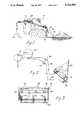
- the apparatusis mounted on a front-end loader for mobility and self-contained on site operation.
- FIG. 1illustrates an embodiment of this invention wherein the soil reclamation equipment is incorporated into a front end loader for on site operation.
- FIG. 2illustrates a schematic diagram of the flow of fluid and slurry within the system shown in FIG. 1.
- FIG. 3shows a top view of the front end loader bucket illustrated in FIG. 1.
- FIG. 4aillustrates a cross-sectional view of the scrubber according to this invention and a schematic diagram of the flow of the various components during operation.
- FIG. 4billustrates an enlarged view of a portion of the scrubber shown in FIG. 4a.
- FIG. 5is a cross-sectional view of the wall of the scrubber according to this invention as seen from line 5--5 in FIG. 4a.
- FIG. 6is a cross-sectional view of the scrubber of this invention as seen from line 6--6 in FIG. 4a.
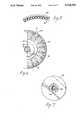
- FIG. 7is a view of one of the rotating disks used in the scrubber of this invention as seen along its axis of rotation.
- the heart of this inventionlies in the fact that several known principles have been combined in a novel arrangement incorporated in a compact and relatively inexpensive apparatus to achieve results heretofore unattained in the soil reclamation field. While the invention is described here in the context of remediation of contaminated soil, it is anticipated that the same technology can be used to separate contaminants from any solid medium that consists of a loose particle aggregate.
- the axial feed adopted by this inventionis significantly different in function from the apparatus shown in the embodiment of FIG. 5 in U.S. Pat. No. 4,399,027 cited above.
- the cyclonic action in that inventionis generated by a separate wash fluid introduced tangentially into the vessel, whereby the heavier particles are washed away in that fluid and the lighter particles are left and withdrawn as product in the feed fluid. The two fluids do not mix and are discharged from separate outlets.
- the separation according to this inventionis further improved by sparging gas into the spinning fluid inwardly from the wall of the cyclone apparatus.
- gasAs gas is liberated through a porous medium, it forms a layer of bubbles that collide and become attached to the lighter particles in the fluid, namely the contaminant and the smallest soil particles, which then form a low density foam that is displaced toward the center of the vortex by the heavier material.
- FIG. 4ashows a cross-sectional view of a scrubber 10 that represents one way of implementing the principles described above.
- the scrubberconsists generally of a self-contained cylindrical separation chamber wherein the entire process of soil reclamation occurs.
- a slurry of contaminated soilis introduced through an inlet port 12, and clean soil fractions are extracted from outlet ports 14 and 16.
- the slurry fluidleaves the scrubber from port 18 and, if necessary, is added as make-up through port 20.
- the spinning motion of the slurryis generated by an assembly of annular disks 40 attached to a hollow shaft 50 connected to a rotating spindle 52.
- This spindleis propelled by the vanes of a turbine 54 powered by a stream of gas delivered to it through the inlet port 24.
- the gas exhausted from the turbineis channelled through a series of ducts (not shown in the drawings) and is used for gas sparging from the interior of the scrubber wall, as described in more detail below.
- the relatively light foam resulting from the aggregation of contaminant and very small soil particles with the gas aphrons released at the wallis collected into the interior of the shaft 50 and into a degassification chamber 56, where the gas is separated from the other phases for ultimate release through the outlet port 22.
- the contaminant and other small debris liberated during the degassification processare released from outlet port 26.
- a water slurry of contaminated soilis created by spraying dry soil with pressurized water during agitation to break u the soil aggregate into its constituent particles.
- the slurryis screened to separate coarse particles (larger than approximately 1/4 inch in diameter) which are virtually contaminant free and therefore need no scrubbing. These coarse particles can instead be readily cleaned of contaminant traces by simple skimming or comparable procedures.
- coarse particles in soilare constituted essentially of electrically neutral sand granules, while the smaller particles are negatively charged clays. Diesel fuel particles are positively charged and are, therefore, attracted to clays more than they are to sand.
- the slurry containing intermediate and fine particlesis then introduced through port 12 tangentially into a feed chamber 70 of the scrubber 10, where the attrition caused by its tangential velocity further contributes to its separation into component particles of various sizes.
- the slurrygradually passes through a collector 72, at the center of the feed chamber, and is directed toward the center of the scrubber which, at steady state, is filled with feed fluid spiraling in a vortex created by the rotation of the disks 40.
- the core of the vortexis filled with a column of foam (shown as 74 in FIG. 4a) generated by gas sparging at the wall.
- foam column 74As the slurry of contaminated soil enters the scrubber from the collector 72, it pushes the foam column 74 outwardly along the axis of the scrubber and through the interior of the shaft 50; at the same time, the slurry is engaged by and mixes with the whirlpool of liquid swirling around the center core.
- the slurrybegins moving in a spiral motion caught up in the existing vortex, its particles acquire a tangential velocity that subjects them to the separation forces described above and classification begins.
- the larger and heavier soil particles(greater than approximately 20 microns) rapidly migrate to the periphery of the vortex where they are directed to a product chamber 76 by channeling baffles 78, and finally exit the scrubber through port 14 as decontaminated soil.
- the outward motion of this heavy materialis aided by the action of the rotating disks 50 which, in creating the liquid vortex, also impart to the fluid velocity components orthogonal to the plane of rotation, away from the disks on the outer edges of the vortex and toward the disks on the inside.
- make-up wateris added through port 20 to replace the void created by their discharge and to recycle residual fine particles in the slurry to the center of the vortex through the annular space 86 between the collector 72 and the baffle 78.
- gasis sparged into the swirling slurry from a series of porous tubes 82 mounted in parallel to the scrubber's main axis along the inside of its wall 84.
- the gaswhich is collected into an annular chamber 80 from the exhaust of the turbine 54, passes through the porous material of tubes 82 (sintered rubber, for example) and forms tiny bubbles that collide with and become attached to the contaminant particles (diesel fuel droplets), as well as to very fine soil particles (approximately less than one micron in diameter) and to various debris particles (such as wood chips) that tend to be impregnated with diesel fuel.
- the resulting aggregate of particles and gasconstitutes a light foam that is rapidly displaced by the heavier fluid and solid material in the spiraling slurry, thus migrating to the core of the vortex to form the foam column 74.
- the formation of this foamis enhanced by the addition of a surfactant to the water slurry.
- this foamis extracted from the separating chamber through the inside of the shaft 50, it is passed through the degassification chamber 56, where it is subjected to steps involving defoaming and phase separation to recover the individual components.
- the diesel fuel obtained from this processis delivered at port 26 from a series of outlet ducts 58 in the degassification chamber 56.
- the diesel fuel so recoveredis of recyclable quality inasmuch as it contains negligible impurities, mostly in the nature of soil particles that can be filtered out, if necessary.
- the gas phase produced in the chamber 56is exhausted to the outlet port 22 through a series of connecting channels not shown in the drawings.
- each annular disk 40is attached to the driving shaft 50 by a set on spokes 92.
- the open spaces between these spokescreate a passage for the slurry to be drawn through as the disks rotate rapidly and spin the fluid radially toward the outside.
- the small annular opening 94resulting from the tight tolerance in the fitting of the first disk within the structure of the scrubber insures that a portion of the slurry so drawn is fed into the channels 88. Since the shaft 50 extends into the slurry beyond the last disk, and since the diameter of the shaft is chosen to approximate the diameter of the foam column at steady state operation, virtually no gas is drawn with the slurry in this stream.
- each hydrocyclone camber 90Upon entering each hydrocyclone camber 90, the slurry is subjected to standard cyclone separation whereby the heavier soil particles are collected at the bottom of the cone and channelled to a common discharge port 16 from an outlet duct 96 (shown in FIG. 4b), and the water is discharged through an outlet duct 98 into the common outlet port 18.
- the soil fines so separatedare contaminant free and can be combined with the larger fraction obtained from port 14.
- the water from port 18contains no visually detectable solid particles and is, therefore, sufficiently clear to be recycled into the slurry of the system.
- the scrubber illustrated in FIGS. 4a, 4b, 5, 6 and 7is approximately 36 inches long and 10 inches in diameter. It is capable of a throughput of 150 tons per day of contaminated soil.
- the scrubber 10is combined with a diesel-powered front-end loader to provide a mobile, self-contained, apparatus for soil reclamation on site.
- the typical front-end loader 100is equipped with a loading bucket 102 that can also be used as a reservoir to generate the water slurry that is fed to the scrubber 10.
- the bucket 102is connected to a 99 gallon water tank 104 through a flexible line 106 and a pump 108 (shown schematically in FIG. 2) that can deliver high pressure water (at approximately 230 psi) to the top of the bucket.
- a pump 108shown schematically in FIG. 2
- the wateris sprayed through nozzles 110 over a load of soil scooped on site from the contaminated area and a slurry is formed by the scrubbing action of the water over the soil aggregate.
- the breaking up of the soil and the formation of the slurryis also aided by a vibration imparted to the bucket by a mechanical shaking mechanism.
- the spray waterentrains soil particles, it flows by gravity to an enclosed lower compartment 112 through a set of apertures 114 screened by 1/4 inch screens (not shown in the drawings) to separate the coarse material from the slurry.
- the slurryis picked up by the suction of a slurry pump 120 from outlet ducts 116 and delivered through a separate line 118 to the scrubber 10 at a pressure of about 75 psi.
- the decontaminated soilcan be dumped directly on the ground after collection from the outlet ports 14 and 16, as illustrated in FIG. 1, or it can be returned to the bucket 102 for temporary storage and placement to its desired destination.
- all lines in the systemare appropriately flexible to accommodate the relative motion of the moving parts on the loader.
- the water produced from the scrubber at port 18is returned to tank 104 and reused in the production of slurry.
- the tankis refilled periodically to replace the moisture lost with the reclaimed soil (generally once a day).
- the scrubber make-up wateris delivered to the inlet port 20 from a line connected to the high pressure pump 108.
- the diesel fuel produced from the output port 26is stored in a separate tank with sufficient capacity for 24 hours of operation.
- this embodiment of the inventionuses the exhaust gases from the diesel engine powering the front-end loader to drive the turbine 54 that operates the scrubber 10.
- hot gasesare released into the turbine vanes at a pressure of about 120 psi and drive the shaft 50 for the creation of the internal vortex that constitutes the basis of the process.
- the gasis exhausted from the turbine into the compartments 80, where it feeds the porous sparging tubes 82 along the interior of the scrubber wall 84.
- the operating temperature in the scrubberrises to about 85 degrees centigrade, which improves the scrubbing properties of the gas and therefore induces better contaminant separation.
- the gasUpon collection of the gas foam from the core of the vortex through the interior of the shaft 50 and recovery of the diesel and other contaminants in the degassification chamber 56, the gas is exhausted from the port 22 and it is recycled into the system for further combustion by connecting it to the input manifold of the diesel engine which also creates the vacuum needed in the chamber.
- the apparatus of this inventionis completely self-contained for many hours of continuous operation.
- the 99 gallon capacityinsures 24 hours of operation without any need for refilling.
- two identical scrubbers 10can be combined coaxially, in mirror image of one another, around a single turbine drive. Whether single or double, the scrubber operates well mounted in any position, although it is shown with a horizontal mount in the drawings.
- a solventcould be used instead of water to create the slurry feed to the scrubber.
- the appropriate solventcould be chosen that would maximize soil and contaminant recovery.
- chemical additivescan be used either with water or other media to improve the efficiency of any step in the process. For example, we found that sodium hexametaphosphate enhances the action of Toxigon 2000. Similarly, the process could obviously be easily adapted to reclaim a slurry of any aggregate of contaminated material for which a suitable slurrying fluid can be found.
Landscapes
- Life Sciences & Earth Sciences (AREA)
- Engineering & Computer Science (AREA)
- Biotechnology (AREA)
- Chemical & Material Sciences (AREA)
- Chemical Kinetics & Catalysis (AREA)
- Physics & Mathematics (AREA)
- Thermal Sciences (AREA)
- Soil Sciences (AREA)
- Environmental & Geological Engineering (AREA)
- Processing Of Solid Wastes (AREA)
Abstract
Description
Claims (21)
Priority Applications (3)
| Application Number | Priority Date | Filing Date | Title |
|---|---|---|---|
| US07/553,536US5114568A (en) | 1990-07-13 | 1990-07-13 | Reclamation system for contaminated material |
| AU82987/91AAU8298791A (en) | 1990-07-12 | 1991-07-12 | Reclamation system for contaminated material |
| PCT/US1991/004936WO1992000789A1 (en) | 1990-07-12 | 1991-07-12 | Reclamation system for contaminated material |
Applications Claiming Priority (1)
| Application Number | Priority Date | Filing Date | Title |
|---|---|---|---|
| US07/553,536US5114568A (en) | 1990-07-13 | 1990-07-13 | Reclamation system for contaminated material |
Publications (1)
| Publication Number | Publication Date |
|---|---|
| US5114568Atrue US5114568A (en) | 1992-05-19 |
Family
ID=24209796
Family Applications (1)
| Application Number | Title | Priority Date | Filing Date |
|---|---|---|---|
| US07/553,536Expired - Fee RelatedUS5114568A (en) | 1990-07-12 | 1990-07-13 | Reclamation system for contaminated material |
Country Status (3)
| Country | Link |
|---|---|
| US (1) | US5114568A (en) |
| AU (1) | AU8298791A (en) |
| WO (1) | WO1992000789A1 (en) |
Cited By (26)
| Publication number | Priority date | Publication date | Assignee | Title |
|---|---|---|---|---|
| US5192423A (en)* | 1992-01-06 | 1993-03-09 | Hydro Processing & Mining Ltd. | Apparatus and method for separation of wet particles |
| WO1993011847A1 (en)* | 1991-12-18 | 1993-06-24 | Vortech International, Inc. | High efficiency centrifugal separation apparatus |
| US5284250A (en)* | 1991-09-13 | 1994-02-08 | Stepenhoff Gary F | Particle separation apparatus |
| US5427944A (en)* | 1994-05-24 | 1995-06-27 | Lee; Sunggyu | Bioremediation of polycyclic aromatic hydrocarbon-contaminated soil |
| US5464536A (en)* | 1992-06-10 | 1995-11-07 | Charles W. Taggart | Apparatus for centrifugally separating a fluid mixture into its component parts |
| US5466385A (en)* | 1992-06-10 | 1995-11-14 | Charles W. Taggart | Gas spurged contrifugation method |
| US5534118A (en)* | 1992-08-13 | 1996-07-09 | Mccutchen; Wilmot H. | Rotary vacuum distillation and desalination apparatus |
| US5639366A (en)* | 1995-09-01 | 1997-06-17 | Bazell Technologies Corporation | Concentrator for solids in a liquid medium |
| US5791491A (en)* | 1994-06-08 | 1998-08-11 | Singleton, Jr.; Robert | Apparatus and method for extracting impurities from a pulpous slurry |
| US5946767A (en)* | 1998-04-02 | 1999-09-07 | Gapvax, Inc. | Pipe cleaning vehicle |
| EP0947217A2 (en) | 1998-04-02 | 1999-10-06 | Pacesetter AB | Apparatus to remove data outliers, produced by external disturbance, in internally measured signals in an implantable cardiac stimulator |
| US6183641B1 (en)* | 1999-01-08 | 2001-02-06 | Fantom Technologies Inc. | Prandtl layer turbine |
| US6204430B1 (en) | 1998-02-18 | 2001-03-20 | Rocky Mountain Remediation Services Llc | Hexametaphosphate as an agent for treating wastes, preparing construction materials and stabilizing soils |
| US6346069B1 (en) | 1999-08-06 | 2002-02-12 | Separation Process Technology, Inc. | Centrifugal pressurized separators and methods of controlling same |
| US6506311B2 (en) | 2001-03-05 | 2003-01-14 | Global Resource Recovery Organization | Method and apparatus for processing wet material |
| US6558079B1 (en)* | 2000-02-22 | 2003-05-06 | Epi Environmental Technologies Inc. | Method and apparatus for covering landfill |
| US6607473B2 (en) | 1999-08-06 | 2003-08-19 | Econova Inc. | Methods for centrifugally separating mixed components of a fluid stream under a pressure differential |
| US6719681B2 (en) | 1999-08-06 | 2004-04-13 | Econova, Inc. | Methods for centrifugally separating mixed components of a fluid stream |
| US6790349B1 (en) | 2003-05-05 | 2004-09-14 | Global Resource Recovery Organization, Inc. | Mobile apparatus for treatment of wet material |
| US20060221764A1 (en)* | 2005-03-17 | 2006-10-05 | Everett Steve E | Method and system for preparing input material for structural building blocks |
| US20070007198A1 (en)* | 2005-07-07 | 2007-01-11 | Loran Balvanz | Method and apparatus for producing dried distiller's grain |
| US20080061004A1 (en)* | 2004-10-29 | 2008-03-13 | Loran Balvanz | Method and apparatus for producing dried distillers grain |
| US20080210630A1 (en)* | 1999-12-16 | 2008-09-04 | Whiteman G Robert | Methods and kits for bioremediation of contaminated soil |
| CN107457268A (en)* | 2017-10-12 | 2017-12-12 | 李林 | A kind of restoration and treatment device of contaminated soil |
| US11383249B2 (en)* | 2020-07-02 | 2022-07-12 | Shimizu Corporation | Washing treatment system and washing treatment method for contaminated soil |
| US11833458B2 (en)* | 2019-11-18 | 2023-12-05 | Lg Chem, Ltd. | Pressurizing centrifugal dehydrator |
Families Citing this family (1)
| Publication number | Priority date | Publication date | Assignee | Title |
|---|---|---|---|---|
| CN106827201B (en)* | 2016-12-30 | 2019-01-04 | 东莞理工学院 | Even automatic glaze spraying machine of pottery |
Citations (30)
| Publication number | Priority date | Publication date | Assignee | Title |
|---|---|---|---|---|
| US994497A (en)* | 1910-03-30 | 1911-06-06 | John J Berrigan | Process of producing starch. |
| US1374447A (en)* | 1916-05-26 | 1921-04-12 | William E Greenawalt | Flotation apparatus |
| US1420138A (en)* | 1921-07-20 | 1922-06-20 | Wilbur H Peck | Process of separating mixed mineral particles of different degrees of specific gravity |
| US2174540A (en)* | 1932-11-08 | 1939-10-03 | Mining Process & Patent Co | Method of ore treatment |
| US2246559A (en)* | 1939-06-22 | 1941-06-24 | Arthur J Weinig | Aerating apparatus |
| US3434598A (en)* | 1968-04-16 | 1969-03-25 | Dejo Inc | Apparatus for treating sewage or industrial waste liquids |
| US3784464A (en)* | 1971-12-23 | 1974-01-08 | Cities Service Canada | Process for washing secondary separator froth to recover bitumen |
| SU545385A1 (en)* | 1975-06-04 | 1977-02-05 | Государственный научно-исследовательский институт цветных металлов "Гинцветмет" | Column flotation machine |
| US4094783A (en)* | 1977-09-29 | 1978-06-13 | Jackson George F | Centrifugal flotation separator |
| DE2812105A1 (en)* | 1978-03-20 | 1979-09-27 | Kloeckner Humboldt Deutz Ag | Selective sepn. by flotation - in centrifugal force field after radial air and water admixture |
| US4214982A (en)* | 1977-08-27 | 1980-07-29 | J. M. Voith Gmbh | Process and device for removing printer's ink from a fiber suspension |
| SU751437A1 (en)* | 1975-02-10 | 1980-07-30 | Научно-Исследовательский И Проектно- Конструкторский Институт Обогащения Твердых Горючих Ископаемых "Иотт" | Centrifugal flotation machine |
| SU789397A1 (en)* | 1978-11-01 | 1980-12-23 | Астраханское центральное конструкторское бюро Министерства речного флота РСФСР | Device for separating three-phase mixture |
| US4279743A (en)* | 1979-11-15 | 1981-07-21 | University Of Utah | Air-sparged hydrocyclone and method |
| US4336136A (en)* | 1980-06-02 | 1982-06-22 | Giguere Marcel L | System for processing soils contaminated by crude oils or other refined petroleum products |
| GB2102308A (en)* | 1981-07-10 | 1983-02-02 | Voith Gmbh J M | A flotation device for processing waste-paper |
| US4397741A (en)* | 1980-08-29 | 1983-08-09 | University Of Utah | Apparatus and method for separating particles from a fluid suspension |
| US4424081A (en)* | 1980-06-02 | 1984-01-03 | Giguere Marcel L | Reconditioning soils contaminated by crude oils or other refined petroleum products |
| FR2539772A1 (en)* | 1983-01-25 | 1984-07-27 | Marvejouls Anne | Centrifugal apparatus for purifying liquid suspensions containing solid impurities |
| GB2148139A (en)* | 1983-10-03 | 1985-05-30 | Pall Corp | Fluid purifier |
| EP0198737A1 (en)* | 1985-03-29 | 1986-10-22 | E. + M. Lamort Société Anonyme dite: | Apparatus for the decontamination of paper pulp |
| US4620671A (en)* | 1983-06-03 | 1986-11-04 | J. M. Voith Gmbh | Method and apparatus for treating waste paper suspensions |
| US4744890A (en)* | 1979-11-15 | 1988-05-17 | University Of Utah | Flotation apparatus and method |
| US4783263A (en)* | 1986-06-17 | 1988-11-08 | Trost Paul B | Detoxification process |
| SU1472132A1 (en)* | 1987-06-15 | 1989-04-15 | Всесоюзный Научно-Исследовательский И Проектно-Конструкторский Институт Микробиологических Производств | Flotation apparatus |
| US4838434A (en)* | 1979-11-15 | 1989-06-13 | University Of Utah | Air sparged hydrocyclone flotation apparatus and methods for separating particles from a particulate suspension |
| US4923125A (en)* | 1988-02-08 | 1990-05-08 | Biotrol, Inc. | Process for treating contaminated soil |
| US4971685A (en)* | 1989-04-11 | 1990-11-20 | The United States Of America As Represented By The Secretary Of The Interior | Bubble injected hydrocyclone flotation cell |
| US4997549A (en)* | 1989-09-19 | 1991-03-05 | Advanced Processing Technologies, Inc. | Air-sparged hydrocyclone separator |
| US5019245A (en)* | 1989-06-02 | 1991-05-28 | Teresa Ignasiak | Method for recovery of hydrocarbons form contaminated soil or refuse materials |
Family Cites Families (2)
| Publication number | Priority date | Publication date | Assignee | Title |
|---|---|---|---|---|
| SU789394A1 (en)* | 1978-10-27 | 1980-12-23 | Институт Металлургии И Обогащения Ан Казахской Сср | Method of vanadium (iv) extraction |
| US4563198A (en)* | 1984-12-04 | 1986-01-07 | Board Of Regents, The University Of Texas System | Method and apparatus for fluid separation |
- 1990
- 1990-07-13USUS07/553,536patent/US5114568A/ennot_activeExpired - Fee Related
- 1991
- 1991-07-12WOPCT/US1991/004936patent/WO1992000789A1/enunknown
- 1991-07-12AUAU82987/91Apatent/AU8298791A/ennot_activeAbandoned
Patent Citations (31)
| Publication number | Priority date | Publication date | Assignee | Title |
|---|---|---|---|---|
| US994497A (en)* | 1910-03-30 | 1911-06-06 | John J Berrigan | Process of producing starch. |
| US1374447A (en)* | 1916-05-26 | 1921-04-12 | William E Greenawalt | Flotation apparatus |
| US1420138A (en)* | 1921-07-20 | 1922-06-20 | Wilbur H Peck | Process of separating mixed mineral particles of different degrees of specific gravity |
| US2174540A (en)* | 1932-11-08 | 1939-10-03 | Mining Process & Patent Co | Method of ore treatment |
| US2246559A (en)* | 1939-06-22 | 1941-06-24 | Arthur J Weinig | Aerating apparatus |
| US3434598A (en)* | 1968-04-16 | 1969-03-25 | Dejo Inc | Apparatus for treating sewage or industrial waste liquids |
| US3784464A (en)* | 1971-12-23 | 1974-01-08 | Cities Service Canada | Process for washing secondary separator froth to recover bitumen |
| SU751437A1 (en)* | 1975-02-10 | 1980-07-30 | Научно-Исследовательский И Проектно- Конструкторский Институт Обогащения Твердых Горючих Ископаемых "Иотт" | Centrifugal flotation machine |
| SU545385A1 (en)* | 1975-06-04 | 1977-02-05 | Государственный научно-исследовательский институт цветных металлов "Гинцветмет" | Column flotation machine |
| US4214982A (en)* | 1977-08-27 | 1980-07-29 | J. M. Voith Gmbh | Process and device for removing printer's ink from a fiber suspension |
| US4094783A (en)* | 1977-09-29 | 1978-06-13 | Jackson George F | Centrifugal flotation separator |
| DE2812105A1 (en)* | 1978-03-20 | 1979-09-27 | Kloeckner Humboldt Deutz Ag | Selective sepn. by flotation - in centrifugal force field after radial air and water admixture |
| SU789397A1 (en)* | 1978-11-01 | 1980-12-23 | Астраханское центральное конструкторское бюро Министерства речного флота РСФСР | Device for separating three-phase mixture |
| US4279743A (en)* | 1979-11-15 | 1981-07-21 | University Of Utah | Air-sparged hydrocyclone and method |
| US4399027A (en)* | 1979-11-15 | 1983-08-16 | University Of Utah Research Foundation | Flotation apparatus and method for achieving flotation in a centrifugal field |
| US4838434A (en)* | 1979-11-15 | 1989-06-13 | University Of Utah | Air sparged hydrocyclone flotation apparatus and methods for separating particles from a particulate suspension |
| US4744890A (en)* | 1979-11-15 | 1988-05-17 | University Of Utah | Flotation apparatus and method |
| US4336136A (en)* | 1980-06-02 | 1982-06-22 | Giguere Marcel L | System for processing soils contaminated by crude oils or other refined petroleum products |
| US4424081A (en)* | 1980-06-02 | 1984-01-03 | Giguere Marcel L | Reconditioning soils contaminated by crude oils or other refined petroleum products |
| US4397741A (en)* | 1980-08-29 | 1983-08-09 | University Of Utah | Apparatus and method for separating particles from a fluid suspension |
| GB2102308A (en)* | 1981-07-10 | 1983-02-02 | Voith Gmbh J M | A flotation device for processing waste-paper |
| FR2539772A1 (en)* | 1983-01-25 | 1984-07-27 | Marvejouls Anne | Centrifugal apparatus for purifying liquid suspensions containing solid impurities |
| US4620671A (en)* | 1983-06-03 | 1986-11-04 | J. M. Voith Gmbh | Method and apparatus for treating waste paper suspensions |
| GB2148139A (en)* | 1983-10-03 | 1985-05-30 | Pall Corp | Fluid purifier |
| EP0198737A1 (en)* | 1985-03-29 | 1986-10-22 | E. + M. Lamort Société Anonyme dite: | Apparatus for the decontamination of paper pulp |
| US4783263A (en)* | 1986-06-17 | 1988-11-08 | Trost Paul B | Detoxification process |
| SU1472132A1 (en)* | 1987-06-15 | 1989-04-15 | Всесоюзный Научно-Исследовательский И Проектно-Конструкторский Институт Микробиологических Производств | Flotation apparatus |
| US4923125A (en)* | 1988-02-08 | 1990-05-08 | Biotrol, Inc. | Process for treating contaminated soil |
| US4971685A (en)* | 1989-04-11 | 1990-11-20 | The United States Of America As Represented By The Secretary Of The Interior | Bubble injected hydrocyclone flotation cell |
| US5019245A (en)* | 1989-06-02 | 1991-05-28 | Teresa Ignasiak | Method for recovery of hydrocarbons form contaminated soil or refuse materials |
| US4997549A (en)* | 1989-09-19 | 1991-03-05 | Advanced Processing Technologies, Inc. | Air-sparged hydrocyclone separator |
Non-Patent Citations (3)
| Title |
|---|
| "Technical Bulletin No. 88-2, Biotrol". |
| Experience with the Harbauer PB3 Soil Cleaning System by H. D. Sonnen, W. Groschel, M. Nels.* |
| Technical Bulletin No. 88 2, Biotrol .* |
Cited By (33)
| Publication number | Priority date | Publication date | Assignee | Title |
|---|---|---|---|---|
| US5284250A (en)* | 1991-09-13 | 1994-02-08 | Stepenhoff Gary F | Particle separation apparatus |
| WO1993011847A1 (en)* | 1991-12-18 | 1993-06-24 | Vortech International, Inc. | High efficiency centrifugal separation apparatus |
| US5229014A (en)* | 1991-12-18 | 1993-07-20 | Vortech International, Inc. | High efficiency centrifugal separation apparatus and method using impeller |
| US5192423A (en)* | 1992-01-06 | 1993-03-09 | Hydro Processing & Mining Ltd. | Apparatus and method for separation of wet particles |
| US5464536A (en)* | 1992-06-10 | 1995-11-07 | Charles W. Taggart | Apparatus for centrifugally separating a fluid mixture into its component parts |
| US5466385A (en)* | 1992-06-10 | 1995-11-14 | Charles W. Taggart | Gas spurged contrifugation method |
| US5534118A (en)* | 1992-08-13 | 1996-07-09 | Mccutchen; Wilmot H. | Rotary vacuum distillation and desalination apparatus |
| US5427944A (en)* | 1994-05-24 | 1995-06-27 | Lee; Sunggyu | Bioremediation of polycyclic aromatic hydrocarbon-contaminated soil |
| US5508194A (en)* | 1994-05-24 | 1996-04-16 | The University Of Akron | Nutrient medium for the bioremediation of polycyclic aromatic hydrocarbon-contaminated soil |
| US5791491A (en)* | 1994-06-08 | 1998-08-11 | Singleton, Jr.; Robert | Apparatus and method for extracting impurities from a pulpous slurry |
| US5639366A (en)* | 1995-09-01 | 1997-06-17 | Bazell Technologies Corporation | Concentrator for solids in a liquid medium |
| US6204430B1 (en) | 1998-02-18 | 2001-03-20 | Rocky Mountain Remediation Services Llc | Hexametaphosphate as an agent for treating wastes, preparing construction materials and stabilizing soils |
| US5946767A (en)* | 1998-04-02 | 1999-09-07 | Gapvax, Inc. | Pipe cleaning vehicle |
| EP0947217A2 (en) | 1998-04-02 | 1999-10-06 | Pacesetter AB | Apparatus to remove data outliers, produced by external disturbance, in internally measured signals in an implantable cardiac stimulator |
| US6013138A (en)* | 1998-04-02 | 2000-01-11 | Gapvax, Inc. | Method for cleaning a pipe with a vehicle |
| US6183641B1 (en)* | 1999-01-08 | 2001-02-06 | Fantom Technologies Inc. | Prandtl layer turbine |
| US6346069B1 (en) | 1999-08-06 | 2002-02-12 | Separation Process Technology, Inc. | Centrifugal pressurized separators and methods of controlling same |
| US7314441B2 (en) | 1999-08-06 | 2008-01-01 | Econova, Inc. | Method for separating particulate matter from a fluid stream |
| US6607473B2 (en) | 1999-08-06 | 2003-08-19 | Econova Inc. | Methods for centrifugally separating mixed components of a fluid stream under a pressure differential |
| US6719681B2 (en) | 1999-08-06 | 2004-04-13 | Econova, Inc. | Methods for centrifugally separating mixed components of a fluid stream |
| US20040192533A1 (en)* | 1999-08-06 | 2004-09-30 | Econova, Inc. | Centrifugal separators |
| US7060017B2 (en) | 1999-08-06 | 2006-06-13 | Econova, Inc. | Centrifugal separators |
| US20060217255A1 (en)* | 1999-08-06 | 2006-09-28 | Econova, Inc. | Method for separating particulate matter from a fluid stream |
| US20080210630A1 (en)* | 1999-12-16 | 2008-09-04 | Whiteman G Robert | Methods and kits for bioremediation of contaminated soil |
| US6558079B1 (en)* | 2000-02-22 | 2003-05-06 | Epi Environmental Technologies Inc. | Method and apparatus for covering landfill |
| US6506311B2 (en) | 2001-03-05 | 2003-01-14 | Global Resource Recovery Organization | Method and apparatus for processing wet material |
| US6790349B1 (en) | 2003-05-05 | 2004-09-14 | Global Resource Recovery Organization, Inc. | Mobile apparatus for treatment of wet material |
| US20080061004A1 (en)* | 2004-10-29 | 2008-03-13 | Loran Balvanz | Method and apparatus for producing dried distillers grain |
| US20060221764A1 (en)* | 2005-03-17 | 2006-10-05 | Everett Steve E | Method and system for preparing input material for structural building blocks |
| US20070007198A1 (en)* | 2005-07-07 | 2007-01-11 | Loran Balvanz | Method and apparatus for producing dried distiller's grain |
| CN107457268A (en)* | 2017-10-12 | 2017-12-12 | 李林 | A kind of restoration and treatment device of contaminated soil |
| US11833458B2 (en)* | 2019-11-18 | 2023-12-05 | Lg Chem, Ltd. | Pressurizing centrifugal dehydrator |
| US11383249B2 (en)* | 2020-07-02 | 2022-07-12 | Shimizu Corporation | Washing treatment system and washing treatment method for contaminated soil |
Also Published As
| Publication number | Publication date |
|---|---|
| AU8298791A (en) | 1992-02-04 |
| WO1992000789A1 (en) | 1992-01-23 |
Similar Documents
| Publication | Publication Date | Title |
|---|---|---|
| US5114568A (en) | Reclamation system for contaminated material | |
| US5053082A (en) | Process and apparatus for cleaning particulate solids | |
| EP2421655B1 (en) | Apparatus and method for separation of phases in a multiphase flow | |
| KR101744849B1 (en) | Purification system and purification method for contaminated soil | |
| US4923125A (en) | Process for treating contaminated soil | |
| US5303871A (en) | Process for treating contaminated soil | |
| KR102395666B1 (en) | Modular type soil washing apparatus for soil remediation | |
| KR101396416B1 (en) | The washing apparatus of oils and heavy metals contaminated soils using thermal stress crushing, the remediation system of oils and heavy metals contaminated soils comprising thereof, and remediation method of oils and heavy metals contaminated soils comprising thereof | |
| US5115986A (en) | Process for treating contaminated soil | |
| WO1989007014A1 (en) | Process for treating contaminated soil | |
| Marino et al. | Heavy metal soil remediation: The effects of attrition scrubbing on a wet gravity concentration process | |
| US6123483A (en) | Method and apparatus for decontaminating soil and mud polluted with hazardous waste and petroleum products | |
| CN219050637U (en) | Mud-water separation device | |
| CN111170551A (en) | Method and device for oil recovery in oily sewage cleaning treatment | |
| JP2013140021A (en) | Cleaning and volume reduction method of radioactive substance-contaminated soil | |
| JP2004216258A (en) | Treatment system for oil-contaminated soil, treatment device and treatment method | |
| US5824210A (en) | Separation of minerals | |
| JP4697719B2 (en) | Method for purifying contaminated soil and separation apparatus used therefor | |
| KR102395659B1 (en) | Modular type washing apparatus for detoxification of incineration ash | |
| US6514128B1 (en) | Apparatus for separating abrasive blasting media from debris | |
| HU214349B (en) | Method and device for continous washing granular substrates | |
| JP4481629B2 (en) | Specific gravity selection method | |
| CN104684450A (en) | Grease trap cleaner | |
| JP2004000820A (en) | Dry type separating method and separating apparatus | |
| JP2006289332A (en) | Method of separating and purifying composite waste debris |
Legal Events
| Date | Code | Title | Description |
|---|---|---|---|
| AS | Assignment | Owner name:FORMULA GROUP LIMITED, ARIZONA Free format text:ASSIGNMENT OF ASSIGNORS INTEREST.;ASSIGNORS:BRINSMEAD, BRIAN J.;STEPENOFF, GARY F.;BESS, VICKI H.;AND OTHERS;REEL/FRAME:005396/0950 Effective date:19900711 | |
| AS | Assignment | Owner name:DRUMMOND, VICTORIA Free format text:APPOINTMENT OF TRUSTEE EFFECTIVE;ASSIGNOR:FORMULA GROUP LIMITED, A CORP. OF AZ, BANKRUPTCY;REEL/FRAME:005935/0615 Effective date:19901024 Owner name:ADVANCED REMEDIATION TREATMENT SYSTEMS, INC. AN Free format text:ASSIGNOR BY BILL OF SALE ASSIGNS ENTIRE INTEREST;ASSIGNOR:FORMULA GROUP LIMITED BY VICTORIA DRUMMOND TRUSTEE IN BANKRUPTCY;REEL/FRAME:005935/0618 Effective date:19901218 Owner name:EARTH SOLUTIONS, INC. A CORP. OF ARIZONA Free format text:ASSIGNMENT OF ASSIGNORS INTEREST.;ASSIGNOR:ADVANCED REMEDIATION TREATMENT SYSTEMS, INC. A CORP. OF ARIZONA;REEL/FRAME:005964/0007 Effective date:19911119 Owner name:EARTH SOLUUTIONS, INC., A CORP. OF AZ Free format text:ASSIGNMENT OF ASSIGNORS INTEREST.;ASSIGNOR:ADVANCED REMEDIATION TREATMENT SYSTEMS, INC. A CORP. OF ARIZONA;REEL/FRAME:005964/0007 Effective date:19911119 | |
| REMI | Maintenance fee reminder mailed | ||
| LAPS | Lapse for failure to pay maintenance fees | ||
| FP | Lapsed due to failure to pay maintenance fee | Effective date:19960522 | |
| STCH | Information on status: patent discontinuation | Free format text:PATENT EXPIRED DUE TO NONPAYMENT OF MAINTENANCE FEES UNDER 37 CFR 1.362 |