US5114443A - Air line vapor trap - Google Patents
Air line vapor trapDownload PDFInfo
- Publication number
- US5114443A US5114443AUS07/773,731US77373191AUS5114443AUS 5114443 AUS5114443 AUS 5114443AUS 77373191 AUS77373191 AUS 77373191AUS 5114443 AUS5114443 AUS 5114443A
- Authority
- US
- United States
- Prior art keywords
- fitting
- liquid
- hollow
- assembly
- sump
- Prior art date
- Legal status (The legal status is an assumption and is not a legal conclusion. Google has not performed a legal analysis and makes no representation as to the accuracy of the status listed.)
- Expired - Fee Related
Links
- 239000007788liquidSubstances0.000claimsabstractdescription24
- 239000012530fluidSubstances0.000claims2
- XLYOFNOQVPJJNP-UHFFFAOYSA-NwaterSubstancesOXLYOFNOQVPJJNP-UHFFFAOYSA-N0.000abstractdescription9
- 239000000835fiberSubstances0.000description3
- 238000007789sealingMethods0.000description3
- 238000010276constructionMethods0.000description2
- 239000000463materialSubstances0.000description2
- 230000002745absorbentEffects0.000description1
- 239000002250absorbentSubstances0.000description1
- 239000004744fabricSubstances0.000description1
- 230000005484gravityEffects0.000description1
- 238000004519manufacturing processMethods0.000description1
- 238000012856packingMethods0.000description1
- 230000001737promoting effectEffects0.000description1
- 238000005507sprayingMethods0.000description1
- 238000005728strengtheningMethods0.000description1
- 239000006200vaporizerSubstances0.000description1
Images
Classifications
- B—PERFORMING OPERATIONS; TRANSPORTING
- B01—PHYSICAL OR CHEMICAL PROCESSES OR APPARATUS IN GENERAL
- B01D—SEPARATION
- B01D46/00—Filters or filtering processes specially modified for separating dispersed particles from gases or vapours
- B01D46/0027—Filters or filtering processes specially modified for separating dispersed particles from gases or vapours with additional separating or treating functions
- B01D46/003—Filters or filtering processes specially modified for separating dispersed particles from gases or vapours with additional separating or treating functions including coalescing means for the separation of liquid
- B01D46/0031—Filters or filtering processes specially modified for separating dispersed particles from gases or vapours with additional separating or treating functions including coalescing means for the separation of liquid with collecting, draining means
- B—PERFORMING OPERATIONS; TRANSPORTING
- B01—PHYSICAL OR CHEMICAL PROCESSES OR APPARATUS IN GENERAL
- B01D—SEPARATION
- B01D46/00—Filters or filtering processes specially modified for separating dispersed particles from gases or vapours
- B01D46/30—Particle separators, e.g. dust precipitators, using loose filtering material
- B—PERFORMING OPERATIONS; TRANSPORTING
- B01—PHYSICAL OR CHEMICAL PROCESSES OR APPARATUS IN GENERAL
- B01D—SEPARATION
- B01D46/00—Filters or filtering processes specially modified for separating dispersed particles from gases or vapours
- B01D46/56—Filters or filtering processes specially modified for separating dispersed particles from gases or vapours with multiple filtering elements, characterised by their mutual disposition
- B01D46/62—Filters or filtering processes specially modified for separating dispersed particles from gases or vapours with multiple filtering elements, characterised by their mutual disposition connected in series
- B—PERFORMING OPERATIONS; TRANSPORTING
- B01—PHYSICAL OR CHEMICAL PROCESSES OR APPARATUS IN GENERAL
- B01D—SEPARATION
- B01D5/00—Condensation of vapours; Recovering volatile solvents by condensation
- B01D5/0078—Condensation of vapours; Recovering volatile solvents by condensation characterised by auxiliary systems or arrangements
- B01D5/009—Collecting, removing and/or treatment of the condensate
- B—PERFORMING OPERATIONS; TRANSPORTING
- B01—PHYSICAL OR CHEMICAL PROCESSES OR APPARATUS IN GENERAL
- B01D—SEPARATION
- B01D50/00—Combinations of methods or devices for separating particles from gases or vapours
- B01D50/20—Combinations of devices covered by groups B01D45/00 and B01D46/00
- B—PERFORMING OPERATIONS; TRANSPORTING
- B01—PHYSICAL OR CHEMICAL PROCESSES OR APPARATUS IN GENERAL
- B01D—SEPARATION
- B01D53/00—Separation of gases or vapours; Recovering vapours of volatile solvents from gases; Chemical or biological purification of waste gases, e.g. engine exhaust gases, smoke, fumes, flue gases, aerosols
- B01D53/26—Drying gases or vapours
- Y—GENERAL TAGGING OF NEW TECHNOLOGICAL DEVELOPMENTS; GENERAL TAGGING OF CROSS-SECTIONAL TECHNOLOGIES SPANNING OVER SEVERAL SECTIONS OF THE IPC; TECHNICAL SUBJECTS COVERED BY FORMER USPC CROSS-REFERENCE ART COLLECTIONS [XRACs] AND DIGESTS
- Y10—TECHNICAL SUBJECTS COVERED BY FORMER USPC
- Y10T—TECHNICAL SUBJECTS COVERED BY FORMER US CLASSIFICATION
- Y10T137/00—Fluid handling
- Y10T137/2931—Diverse fluid containing pressure systems
- Y10T137/3109—Liquid filling by evacuating container
Definitions
- the present inventionis directed to devices of a type adapted to remove oil and/or water vapor from a flowing gaseous medium such as compressed air, and more particularly to improved drainage of devices of this character.
- U.S. Pat. No. 4,487,618 assigned to the assignee hereofdiscloses an in-line trap for removing water and/or oil vapor from a compressed air line which includes a manifold having spaced coaxial inlet and outlet openings and a hollow base suspended from the manifold
- a first cartridgeextends between the manifold inlet and the enclosed volume within the hollow base, and contains a wire pad adapted to coalesce water and/or oil vapor in air passing therethrough into droplets which are then entrained by the air and carried into the base volume
- An integral honeycomb structurecooperates with the bottom and side walls of the base to form a dead airspace which captures water droplets falling from air entering the enclosed volume from the first cartridge.
- a second cartridgewhich includes spirally wound fiber and wire mesh materials, directs compressed air from within the enclosed base volume to the manifold outlet and simultaneously functions to remove any remaining vapor therefrom.
- a depression in the bottom wall of the baseforms a liquid sump for collection of water and/or oil removed from the compressed air.
- a conventional drain mechanismincluding a T-shaped draincock, is mounted in the base wall depression for selectively draining liquid collected therein.
- U.S. Pat. No. 4,600,416discloses an improvement upon such commercial device in which the drain features an open annular orifice for continuous weep-drainage of liquid under pressure The orifice surrounds a wire having an angulated head disposed within the sump. The wire may be rotated by an operator so as to remove dirt and debris from surrounding and clogging the annular weep orifice.
- the continuously-open weep draincauses a significant and undesirable loss of air pressure
- liquid ejected from the trap puddles or pools beneath the weep drainwhich is often undesirable in a manufacturing environment. It is therefore a general object of the present invention to provide an air line vapor trap of the described character which features an improved drain structure for continuously and automatically draining liquid collected in the trap sump without substantially reducing pressure in the main air line and without spraying the liquid into the surrounding environment.
- an air line vapor trap of the described typeis characterized in that a second enclosure is suspended by an open fitting beneath the drain sump, and a hollow tube extends from within the second enclosure through the fitting and sump to the entrance to the second cartridge. Air is thus aspirated through the tube from within the second enclosure so as to draw liquid from the sump through the fitting into the second enclosure.
- the tubeis carried by a collar mounted within the second enclosure beneath the fitting and communicates with a central opening in such collar.
- An array of drain openingssurround the central opening in the collar, and an axially and radially flared skirt surrounds the central opening and is positioned beneath the array of drain openings.
- a float drain or the likeis carried at the lower portion of the second enclosure for periodically draining liquid collected therein to a suitable collection tank or the like.
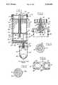
- FIG. 1is an elevational bisectional view taken in a vertical plane through the vapor trap in accordance with a presently preferred embodiment of the invention
- FIG. 2is a fragmentary view of the trap in FIG. 1 featuring a portion of the drain mechanism on an enlarged scale;
- FIGS. 3 and 4are sectional views taken substantially along the respective lines 3--3 and 4--4 in FIGS. 2 and 1;
- FIG. 5is a view similar to that of FIG. 3 but illustrating a modified embodiment of the invention.
- FIG. 1illustrates a presently preferred embodiment 10 of a vapor trap in accordance with the invention as comprising a cap or manifold 12 having oppositely directed and coaxially aligned internally threaded openings 14,16 respectively defining an inlet and outlet adapted for in-line connection to a gas line such as a compressed air line.
- a concave internal surface 18 on manifold 12 internally opposed to inlet opening 14directs inlet air orthogonally of the inlet axis, or downwardly in the orientation of FIG 1.
- a concave surface 20 opposed to outlet opening 16receives and directs upwardly flowing air to outlet opening 16.
- a hollow base 22 of generally rectangular constructioncomprises a bottom wall plate 24 and a continuous sidewall 25 peripherally contiguous with bottom wall plate 24 and separated therefrom by the gasket 26.
- Base 22thus forms an enclosed volume 28 suspended beneath and fastened to manifold 12 by the bolts 30.
- a pair of laterally spaced circular openings 32,34are formed in base 22 in respective alignment in assembly with the inlet and outlet of manifold 12.
- An integral honeycomb structure 36is disposed in the lower portion of enclosed volume 28 adjacent to bottom wall plate 24 and cooperates with the side and bottom walls of enclosure 22 to define a zone of substantially zero air movement adjacent to the enclosure bottom wall.
- a pair of laterally spaced replaceable vaporizer cartridges 38,40are clamped by bolts 30 between manifold 12 and base 22 in sealing engagement therewith.
- Cartridge 38which is clamped in axial alignment between the inlet section of manifold 12 and opening 32 in base 22, comprises a cylindrical cartridge case 42 and an axially spaced pair of open end qaskets 44 clamped in sealing engagement with manifold 12 and base 22 respectively
- cartridge 38comprises a mass or pad 48 of wire mesh fibers of a type adapted to coalesce water or oil vapor passing therethrough into vapor droplets.
- Pad 48 in the preferred embodiment of the inventioncomprises a so-called "Goodloe column packing" of a type disclosed in U.S. Pat. No. 2,521,785.
- cartridge 38cross-sectional to air flow is substantially less than that of the enclosed volume 28 within base 22.
- Cartridge 40which is clamped in axial alignment between the outlet portion of manifold 12 and base opening 34, comprises an outer cylindrical case 50 and a pair of end gaskets 44,45 in respective sealing engagement with manifold 12 and base 22.
- a plug structure 52 of absorbent fabric interwoven with strengthening wire threadsis within cartridge case 50 and between end gaskets 44,45, and filling the entire cartridge volume.
- honeycomb structure 36Since the construction of honeycomb structure 36 prevents substantial air movement therewithin, revaporization is substantially eliminated In the meantime, the compressed air stream, which is now 75% to 95% dry, is fed from enclosed volume 28 through opening 34 into cartridge 40. As the air passes upwardly through the fiber/mesh plug 52 toward outlet 16, any remaining vapor is removed by the fibrous plug material.
- a depression 60is formed in bottom wall plate 24, beneath honeycomb structure 36 and the dead air space provided thereby, to serve as a sump for liquid removed from the compressed air stream.
- sump 60is positioned beneath opening 34 coaxially therewith
- An enclosure 62is suspended from sump 60 by the hollow fitting 64 which is threadably received into a corresponding opening in sump 60.
- Enclosure 62comprises a bowl 66 having an open edge suspended from the periphery of an enclosure top 68.
- Top 68has a central opening 70 into which the lower end fitting 64 is threadably received Opening 70 is outwardly and downwardly flared, as best seen in FIG. 2, and has a collar 72 threadably received therein from within enclosure 62 coaxially with fitting 64.
- Collar 72has a circular central passage 74, and has a circumferential array of passages 76 extending axially therethrough surrounding central passage 74.
- a rigid tube 78is press-fitted into a counterbore in central passage 74 and extends upwardly through opening 70, fitting 64, sump 60 and honeycomb 36 to terminate at opening 34 (FIG. 1) coaxially therewith
- a conical skirt 80integrally depends from collar 72 surrounding central opening 74 and flares axially and radially therefrom beneath passages 76.
- air flowing from within enclosed volume 28 through opening 34 to cartridge 40exhibits increase in velocity due to decrease in effective cross-sectional area.
- the air-passage opening 34 and the central opening in gasket 45are smaller than opening 32 and the corresponding passage in gaskets 44 in order to enhance such velocity increase.
- Airis aspirated upwardly through tube 28 and central passage 74, which thus draws a small amount of air from within volume 28 through fitting 64 surrounding tube 78 and through openings 76 into enclosure 62.
- Such air flow through fitting 64draws liquid from sump 60 through opening 70 and through openings 76 in collar 72.
- Such liquidimpinges upon and drips from skirt 80, which thus prevents flow of liquid along collar 72 and re-aspiration through tube 78.
- a float drain or other conventional device 81is positioned at the lower end of bowl 66 for periodically draining liquid therefrom into a suitable collection tank or the like (not shown).
- FIG. 5illustrates a modified collar 72a wherein the multiplicity of circular opening 76 in the embodiment of FIG. 3 are replaced by a pair of kidney-shaped openings 76a extending at constant radius around central opening 74.
- FIG. 4illustrates an improvement in manifold 12 whereby ribs 82 extend from surface 20 and thus help support gasket 44 against pressure surges in air passing through the vapor trap.
- FIG. 1also illustrates a further improvement in the prior art traps hereinabove described whereby a baffle 84 projects downwardly from the central boss 86 within enclosed volume 28 for promoting downward circulation of air toward honeycomb 36.
Landscapes
- Chemical & Material Sciences (AREA)
- Chemical Kinetics & Catalysis (AREA)
- Engineering & Computer Science (AREA)
- Analytical Chemistry (AREA)
- General Chemical & Material Sciences (AREA)
- Oil, Petroleum & Natural Gas (AREA)
- Filtering Of Dispersed Particles In Gases (AREA)
- Separating Particles In Gases By Inertia (AREA)
Abstract
Description
Claims (10)
Priority Applications (1)
| Application Number | Priority Date | Filing Date | Title |
|---|---|---|---|
| US07/773,731US5114443A (en) | 1987-11-02 | 1991-08-27 | Air line vapor trap |
Applications Claiming Priority (3)
| Application Number | Priority Date | Filing Date | Title |
|---|---|---|---|
| US11541687A | 1987-11-02 | 1987-11-02 | |
| US72676091A | 1991-07-08 | 1991-07-08 | |
| US07/773,731US5114443A (en) | 1987-11-02 | 1991-08-27 | Air line vapor trap |
Related Parent Applications (1)
| Application Number | Title | Priority Date | Filing Date |
|---|---|---|---|
| US72676091AContinuation | 1987-11-02 | 1991-07-08 |
Publications (1)
| Publication Number | Publication Date |
|---|---|
| US5114443Atrue US5114443A (en) | 1992-05-19 |
Family
ID=27381660
Family Applications (1)
| Application Number | Title | Priority Date | Filing Date |
|---|---|---|---|
| US07/773,731Expired - Fee RelatedUS5114443A (en) | 1987-11-02 | 1991-08-27 | Air line vapor trap |
Country Status (1)
| Country | Link |
|---|---|
| US (1) | US5114443A (en) |
Cited By (4)
| Publication number | Priority date | Publication date | Assignee | Title |
|---|---|---|---|---|
| US5655570A (en)* | 1996-05-21 | 1997-08-12 | Permea, Inc. | Condensate drain device |
| US20090287204A1 (en)* | 2005-01-14 | 2009-11-19 | Co-Repair, Inc. | System And Method For The Treatment Of Heart Tissue |
| US20120288773A1 (en)* | 2006-09-13 | 2012-11-15 | Daimler Ag | Apparatus for Humidifying a Gas Flow |
| US20170232361A1 (en)* | 2013-01-25 | 2017-08-17 | Geoff Todosiev | Vapor trap |
Citations (24)
| Publication number | Priority date | Publication date | Assignee | Title |
|---|---|---|---|---|
| US426880A (en)* | 1890-04-29 | Steam-separator | ||
| US756942A (en)* | 1902-06-06 | 1904-04-12 | John G Thompson | Steam-separator. |
| US1115505A (en)* | 1913-02-21 | 1914-11-03 | Armstrong Paint And Varnish Works | Strainer. |
| US1325991A (en)* | 1919-12-23 | Bottle-filling device | ||
| US1443428A (en)* | 1922-02-23 | 1923-01-30 | James G Nolen | Auxiliary fuel reservoir |
| US1856685A (en)* | 1928-05-19 | 1932-05-03 | Int Precipitation Co | Apparatus for separating solids from gases |
| US2521785A (en)* | 1948-04-09 | 1950-09-12 | Metal Textile Corp | Separator for removing entrained liquid particles from a flowing gaseous medium |
| FR1011989A (en)* | 1949-02-05 | 1952-07-02 | Dingler Werke A G | Method and device for separating the finest dust and flour from the gases |
| US2638218A (en)* | 1949-11-21 | 1953-05-12 | Farm Production Engineers Inc | Method of separating dispersed matter from fluid masses |
| US3093467A (en)* | 1958-09-15 | 1963-06-11 | William I Mclaughlin | Vapor separator and filter for compressed air |
| US3402529A (en)* | 1965-10-06 | 1968-09-24 | White Sales Corp Graham | Air filter assembly |
| GB1146262A (en)* | 1966-05-23 | 1969-03-26 | Gen Electric | Apparatus for removing entrained particles from a vapor or a gas |
| US3488927A (en)* | 1967-10-23 | 1970-01-13 | Shell Oil Co | Gas-liquid cyclone separator |
| US3559764A (en)* | 1968-06-05 | 1971-02-02 | Harry L Wheeler Jr | Selective filter, regulator and lubricator component arrangement for air lines |
| US4385913A (en)* | 1981-11-27 | 1983-05-31 | Lane Arlo E | Device for eliminating droplets of liquid from a gas stream |
| US4487618A (en)* | 1982-08-19 | 1984-12-11 | La-Man Corporation | Airline vapor trap |
| US4600416A (en)* | 1985-02-08 | 1986-07-15 | La-Man Corporation | Air line vapor trap |
| US4678488A (en)* | 1985-05-02 | 1987-07-07 | Sensors, Inc. | Liquid separator for gas analyzer |
| USRE32989E (en)* | 1985-02-08 | 1989-07-18 | La-Man Corporation | Air line vapor trap |
| US4848989A (en)* | 1986-08-29 | 1989-07-18 | Maeda Shell Service Co., Ltd. | In-line filter assembly for compressed air |
| US4865815A (en)* | 1987-06-01 | 1989-09-12 | La-Man Corporation | In-line compressed air carbon monoxide filter |
| US4874408A (en)* | 1987-11-02 | 1989-10-17 | La-Man Corporation | Liquid drain assembly |
| US4897094A (en)* | 1988-04-05 | 1990-01-30 | Maeda Shell Service Co., Ltd. and J&M Co., Ltd. | In-line filter assembly for compressed air |
| US5030262A (en)* | 1987-11-02 | 1991-07-09 | La-Man Corporation | Air vapor trap and drain therefore |
- 1991
- 1991-08-27USUS07/773,731patent/US5114443A/ennot_activeExpired - Fee Related
Patent Citations (24)
| Publication number | Priority date | Publication date | Assignee | Title |
|---|---|---|---|---|
| US426880A (en)* | 1890-04-29 | Steam-separator | ||
| US1325991A (en)* | 1919-12-23 | Bottle-filling device | ||
| US756942A (en)* | 1902-06-06 | 1904-04-12 | John G Thompson | Steam-separator. |
| US1115505A (en)* | 1913-02-21 | 1914-11-03 | Armstrong Paint And Varnish Works | Strainer. |
| US1443428A (en)* | 1922-02-23 | 1923-01-30 | James G Nolen | Auxiliary fuel reservoir |
| US1856685A (en)* | 1928-05-19 | 1932-05-03 | Int Precipitation Co | Apparatus for separating solids from gases |
| US2521785A (en)* | 1948-04-09 | 1950-09-12 | Metal Textile Corp | Separator for removing entrained liquid particles from a flowing gaseous medium |
| FR1011989A (en)* | 1949-02-05 | 1952-07-02 | Dingler Werke A G | Method and device for separating the finest dust and flour from the gases |
| US2638218A (en)* | 1949-11-21 | 1953-05-12 | Farm Production Engineers Inc | Method of separating dispersed matter from fluid masses |
| US3093467A (en)* | 1958-09-15 | 1963-06-11 | William I Mclaughlin | Vapor separator and filter for compressed air |
| US3402529A (en)* | 1965-10-06 | 1968-09-24 | White Sales Corp Graham | Air filter assembly |
| GB1146262A (en)* | 1966-05-23 | 1969-03-26 | Gen Electric | Apparatus for removing entrained particles from a vapor or a gas |
| US3488927A (en)* | 1967-10-23 | 1970-01-13 | Shell Oil Co | Gas-liquid cyclone separator |
| US3559764A (en)* | 1968-06-05 | 1971-02-02 | Harry L Wheeler Jr | Selective filter, regulator and lubricator component arrangement for air lines |
| US4385913A (en)* | 1981-11-27 | 1983-05-31 | Lane Arlo E | Device for eliminating droplets of liquid from a gas stream |
| US4487618A (en)* | 1982-08-19 | 1984-12-11 | La-Man Corporation | Airline vapor trap |
| US4600416A (en)* | 1985-02-08 | 1986-07-15 | La-Man Corporation | Air line vapor trap |
| USRE32989E (en)* | 1985-02-08 | 1989-07-18 | La-Man Corporation | Air line vapor trap |
| US4678488A (en)* | 1985-05-02 | 1987-07-07 | Sensors, Inc. | Liquid separator for gas analyzer |
| US4848989A (en)* | 1986-08-29 | 1989-07-18 | Maeda Shell Service Co., Ltd. | In-line filter assembly for compressed air |
| US4865815A (en)* | 1987-06-01 | 1989-09-12 | La-Man Corporation | In-line compressed air carbon monoxide filter |
| US4874408A (en)* | 1987-11-02 | 1989-10-17 | La-Man Corporation | Liquid drain assembly |
| US5030262A (en)* | 1987-11-02 | 1991-07-09 | La-Man Corporation | Air vapor trap and drain therefore |
| US4897094A (en)* | 1988-04-05 | 1990-01-30 | Maeda Shell Service Co., Ltd. and J&M Co., Ltd. | In-line filter assembly for compressed air |
Cited By (8)
| Publication number | Priority date | Publication date | Assignee | Title |
|---|---|---|---|---|
| US5655570A (en)* | 1996-05-21 | 1997-08-12 | Permea, Inc. | Condensate drain device |
| US20090287204A1 (en)* | 2005-01-14 | 2009-11-19 | Co-Repair, Inc. | System And Method For The Treatment Of Heart Tissue |
| US20120288773A1 (en)* | 2006-09-13 | 2012-11-15 | Daimler Ag | Apparatus for Humidifying a Gas Flow |
| US8408524B2 (en)* | 2006-09-13 | 2013-04-02 | Daimler Ag | Apparatus for humidifying a gas flow |
| US20170232361A1 (en)* | 2013-01-25 | 2017-08-17 | Geoff Todosiev | Vapor trap |
| US9901843B2 (en)* | 2013-01-25 | 2018-02-27 | Geoff Todosiev | Vapor trap |
| US20180178140A1 (en)* | 2013-01-25 | 2018-06-28 | Geoff Todosiev | Vapor trap |
| US10898827B2 (en)* | 2013-01-25 | 2021-01-26 | Geoff Todosiev | Vapor trap |
Similar Documents
| Publication | Publication Date | Title |
|---|---|---|
| US4600416A (en) | Air line vapor trap | |
| US4162904A (en) | Silencer-separator device | |
| US4874408A (en) | Liquid drain assembly | |
| US4925466A (en) | Filter cartridge assembly | |
| US5145497A (en) | In-line filter device for compressed air having mist filter and air collector | |
| US5417848A (en) | Coalescence separator with changeable coalescence element | |
| JPH01194919A (en) | Back flow depth filter assembly and production thereof | |
| JP3913272B2 (en) | Liquid removal instrument for surface cleaning or drying and liquid collection container used therefor | |
| KR960010373B1 (en) | In-line filter unit for compressed air | |
| US2580317A (en) | Purger | |
| US5114443A (en) | Air line vapor trap | |
| USRE32989E (en) | Air line vapor trap | |
| US5030262A (en) | Air vapor trap and drain therefore | |
| KR102247189B1 (en) | Paint Mist and Oil mist Collector by Centrifugation | |
| US3134825A (en) | Gas treating device and system | |
| US5228890A (en) | Cyclone separator | |
| TWM651178U (en) | Oil bath filter device | |
| US4274844A (en) | Evaporator | |
| RU2299414C1 (en) | Personal sampler | |
| RU2256488C1 (en) | Droplet separator | |
| JPH061210Y2 (en) | Steam separator | |
| RU7896U1 (en) | HUMIDIFIER | |
| RU2042434C1 (en) | Centrifugal separator | |
| JPH0621536Y2 (en) | Steam separator | |
| CN217163721U (en) | Cyclone oil-gas separation device |
Legal Events
| Date | Code | Title | Description |
|---|---|---|---|
| FPAY | Fee payment | Year of fee payment:4 | |
| FEPP | Fee payment procedure | Free format text:PAT HLDR NO LONGER CLAIMS SMALL ENT STAT AS INDIV INVENTOR (ORIGINAL EVENT CODE: LSM1); ENTITY STATUS OF PATENT OWNER: LARGE ENTITY | |
| FEPP | Fee payment procedure | Free format text:PAYOR NUMBER ASSIGNED (ORIGINAL EVENT CODE: ASPN); ENTITY STATUS OF PATENT OWNER: LARGE ENTITY | |
| AS | Assignment | Owner name:SOUTHTRUST BANK, A NATIONAL BANKING ASSOCIATION, A Free format text:PATENT COLLATERAL ASSIGNMENT;ASSIGNORS:DISPLAY TECHNOLOGIES, INC., A CORP. OF NEVADA;LA-MAN CORPORATION, A CORP. OF NEVADA;REEL/FRAME:010061/0345 Effective date:19990602 | |
| AS | Assignment | Owner name:DISPLAY TECHNOLOGIES, INC. A CORPORATION OF NEVADA Free format text:CHANGE OF NAME;ASSIGNOR:LA-MAN CORPORATION, A CORPORATION OF NEVADA;REEL/FRAME:010226/0446 Effective date:19990825 Owner name:LA-MAN CORPORATION, A CORPORATION OF NEVADA, FLORI Free format text:ASSIGNMENT OF ASSIGNORS INTEREST;ASSIGNOR:DISPLAY TECHNOLOGIES, INC.;REEL/FRAME:010216/0757 Effective date:19990825 | |
| AS | Assignment | Owner name:DISPLAY TECHNOLOGIES, INC., A CORPORATION OF NEVAD Free format text:CHANGE OF NAME;ASSIGNOR:LA-MAN CORPORATION, A CORPORATION OF NEVADA;REEL/FRAME:010404/0001 Effective date:19990825 | |
| FPAY | Fee payment | Year of fee payment:8 | |
| AS | Assignment | Owner name:SOUTHTRUST BANK, ALABAMA Free format text:SECURITY INTEREST;ASSIGNORS:DISPLAY TECHNOLOGIES, INC.;LA-MAN CORPORATION;REEL/FRAME:011170/0233 Effective date:20000926 | |
| AS | Assignment | Owner name:LA-MAN CORPORATION, FLORIDA Free format text:RELEASE OF SECURITY INTEREST;ASSIGNOR:SOUTH TRUST BANK;REEL/FRAME:011506/0165 Effective date:20010202 | |
| FEPP | Fee payment procedure | Free format text:PAYER NUMBER DE-ASSIGNED (ORIGINAL EVENT CODE: RMPN); ENTITY STATUS OF PATENT OWNER: LARGE ENTITY Free format text:PAYOR NUMBER ASSIGNED (ORIGINAL EVENT CODE: ASPN); ENTITY STATUS OF PATENT OWNER: LARGE ENTITY | |
| REMI | Maintenance fee reminder mailed | ||
| LAPS | Lapse for failure to pay maintenance fees | ||
| FP | Lapsed due to failure to pay maintenance fee | Effective date:20040519 | |
| STCH | Information on status: patent discontinuation | Free format text:PATENT EXPIRED DUE TO NONPAYMENT OF MAINTENANCE FEES UNDER 37 CFR 1.362 |