US5113951A - Apparatus for driving a drilling or percussion tool - Google Patents
Apparatus for driving a drilling or percussion toolDownload PDFInfo
- Publication number
- US5113951A US5113951AUS07/713,410US71341091AUS5113951AUS 5113951 AUS5113951 AUS 5113951AUS 71341091 AUS71341091 AUS 71341091AUS 5113951 AUS5113951 AUS 5113951A
- Authority
- US
- United States
- Prior art keywords
- housing
- tool
- plate
- motor
- percussion
- Prior art date
- Legal status (The legal status is an assumption and is not a legal conclusion. Google has not performed a legal analysis and makes no representation as to the accuracy of the status listed.)
- Expired - Lifetime
Links
- 238000009527percussionMethods0.000titleabstractdescription55
- 238000005553drillingMethods0.000titleabstractdescription10
- 238000001816coolingMethods0.000claimsdescription10
- 239000000463materialSubstances0.000claimsdescription2
- 238000005192partitionMethods0.000claimsdescription2
- 230000033001locomotionEffects0.000abstractdescription29
- 230000005540biological transmissionEffects0.000abstractdescription12
- 230000003534oscillatory effectEffects0.000abstractdescription3
- 230000007246mechanismEffects0.000description10
- 210000002105tongueAnatomy0.000description10
- 230000006835compressionEffects0.000description8
- 238000007906compressionMethods0.000description8
- 230000008878couplingEffects0.000description8
- 238000010168coupling processMethods0.000description8
- 238000005859coupling reactionMethods0.000description8
- 239000000428dustSubstances0.000description5
- 238000010276constructionMethods0.000description4
- 230000000694effectsEffects0.000description4
- 238000005096rolling processMethods0.000description3
- 230000009471actionEffects0.000description1
- 238000005452bendingMethods0.000description1
- 230000008901benefitEffects0.000description1
- 238000006243chemical reactionMethods0.000description1
- 210000000078clawAnatomy0.000description1
- 230000003111delayed effectEffects0.000description1
- 238000006073displacement reactionMethods0.000description1
- 230000002349favourable effectEffects0.000description1
- 230000014759maintenance of locationEffects0.000description1
- 230000010355oscillationEffects0.000description1
- 239000011435rockSubstances0.000description1
- 230000007704transitionEffects0.000description1
Images


Classifications
- B—PERFORMING OPERATIONS; TRANSPORTING
- B25—HAND TOOLS; PORTABLE POWER-DRIVEN TOOLS; MANIPULATORS
- B25F—COMBINATION OR MULTI-PURPOSE TOOLS NOT OTHERWISE PROVIDED FOR; DETAILS OR COMPONENTS OF PORTABLE POWER-DRIVEN TOOLS NOT PARTICULARLY RELATED TO THE OPERATIONS PERFORMED AND NOT OTHERWISE PROVIDED FOR
- B25F5/00—Details or components of portable power-driven tools not particularly related to the operations performed and not otherwise provided for
- B25F5/008—Cooling means
- B—PERFORMING OPERATIONS; TRANSPORTING
- B23—MACHINE TOOLS; METAL-WORKING NOT OTHERWISE PROVIDED FOR
- B23Q—DETAILS, COMPONENTS, OR ACCESSORIES FOR MACHINE TOOLS, e.g. ARRANGEMENTS FOR COPYING OR CONTROLLING; MACHINE TOOLS IN GENERAL CHARACTERISED BY THE CONSTRUCTION OF PARTICULAR DETAILS OR COMPONENTS; COMBINATIONS OR ASSOCIATIONS OF METAL-WORKING MACHINES, NOT DIRECTED TO A PARTICULAR RESULT
- B23Q11/00—Accessories fitted to machine tools for keeping tools or parts of the machine in good working condition or for cooling work; Safety devices specially combined with or arranged in, or specially adapted for use in connection with, machine tools
- B23Q11/0042—Devices for removing chips
- B23Q11/0046—Devices for removing chips by sucking
- B—PERFORMING OPERATIONS; TRANSPORTING
- B25—HAND TOOLS; PORTABLE POWER-DRIVEN TOOLS; MANIPULATORS
- B25D—PERCUSSIVE TOOLS
- B25D11/00—Portable percussive tools with electromotor or other motor drive
- B25D11/005—Arrangements for adjusting the stroke of the impulse member or for stopping the impact action when the tool is lifted from the working surface
- B—PERFORMING OPERATIONS; TRANSPORTING
- B25—HAND TOOLS; PORTABLE POWER-DRIVEN TOOLS; MANIPULATORS
- B25D—PERCUSSIVE TOOLS
- B25D16/00—Portable percussive machines with superimposed rotation, the rotational movement of the output shaft of a motor being modified to generate axial impacts on the tool bit
- B—PERFORMING OPERATIONS; TRANSPORTING
- B25—HAND TOOLS; PORTABLE POWER-DRIVEN TOOLS; MANIPULATORS
- B25D—PERCUSSIVE TOOLS
- B25D17/00—Details of, or accessories for, portable power-driven percussive tools
- B—PERFORMING OPERATIONS; TRANSPORTING
- B25—HAND TOOLS; PORTABLE POWER-DRIVEN TOOLS; MANIPULATORS
- B25D—PERCUSSIVE TOOLS
- B25D17/00—Details of, or accessories for, portable power-driven percussive tools
- B25D17/04—Handles; Handle mountings
- B—PERFORMING OPERATIONS; TRANSPORTING
- B23—MACHINE TOOLS; METAL-WORKING NOT OTHERWISE PROVIDED FOR
- B23B—TURNING; BORING
- B23B2270/00—Details of turning, boring or drilling machines, processes or tools not otherwise provided for
- B23B2270/30—Chip guiding or removal
- B—PERFORMING OPERATIONS; TRANSPORTING
- B25—HAND TOOLS; PORTABLE POWER-DRIVEN TOOLS; MANIPULATORS
- B25D—PERCUSSIVE TOOLS
- B25D2211/00—Details of portable percussive tools with electromotor or other motor drive
- B25D2211/003—Crossed drill and motor spindles
- B—PERFORMING OPERATIONS; TRANSPORTING
- B25—HAND TOOLS; PORTABLE POWER-DRIVEN TOOLS; MANIPULATORS
- B25D—PERCUSSIVE TOOLS
- B25D2211/00—Details of portable percussive tools with electromotor or other motor drive
- B25D2211/06—Means for driving the impulse member
- B25D2211/061—Swash-plate actuated impulse-driving mechanisms
- B—PERFORMING OPERATIONS; TRANSPORTING
- B25—HAND TOOLS; PORTABLE POWER-DRIVEN TOOLS; MANIPULATORS
- B25D—PERCUSSIVE TOOLS
- B25D2217/00—Details of, or accessories for, portable power-driven percussive tools
- B25D2217/0073—Arrangements for damping of the reaction force
- B25D2217/0076—Arrangements for damping of the reaction force by use of counterweights
- B25D2217/0092—Arrangements for damping of the reaction force by use of counterweights being spring-mounted
- B—PERFORMING OPERATIONS; TRANSPORTING
- B25—HAND TOOLS; PORTABLE POWER-DRIVEN TOOLS; MANIPULATORS
- B25D—PERCUSSIVE TOOLS
- B25D2250/00—General details of portable percussive tools; Components used in portable percussive tools
- B25D2250/045—Cams used in percussive tools
- B—PERFORMING OPERATIONS; TRANSPORTING
- B25—HAND TOOLS; PORTABLE POWER-DRIVEN TOOLS; MANIPULATORS
- B25D—PERCUSSIVE TOOLS
- B25D2250/00—General details of portable percussive tools; Components used in portable percussive tools
- B25D2250/275—Tools having at least two similar components
- B25D2250/281—Double motors
- Y—GENERAL TAGGING OF NEW TECHNOLOGICAL DEVELOPMENTS; GENERAL TAGGING OF CROSS-SECTIONAL TECHNOLOGIES SPANNING OVER SEVERAL SECTIONS OF THE IPC; TECHNICAL SUBJECTS COVERED BY FORMER USPC CROSS-REFERENCE ART COLLECTIONS [XRACs] AND DIGESTS
- Y10—TECHNICAL SUBJECTS COVERED BY FORMER USPC
- Y10T—TECHNICAL SUBJECTS COVERED BY FORMER US CLASSIFICATION
- Y10T408/00—Cutting by use of rotating axially moving tool
- Y10T408/44—Cutting by use of rotating axially moving tool with means to apply transient, fluent medium to work or product
- Y10T408/45—Cutting by use of rotating axially moving tool with means to apply transient, fluent medium to work or product including Tool with duct
- Y10T408/453—Cutting by use of rotating axially moving tool with means to apply transient, fluent medium to work or product including Tool with duct and means to move gaseous fluid by application of vacuum
- Y—GENERAL TAGGING OF NEW TECHNOLOGICAL DEVELOPMENTS; GENERAL TAGGING OF CROSS-SECTIONAL TECHNOLOGIES SPANNING OVER SEVERAL SECTIONS OF THE IPC; TECHNICAL SUBJECTS COVERED BY FORMER USPC CROSS-REFERENCE ART COLLECTIONS [XRACs] AND DIGESTS
- Y10—TECHNICAL SUBJECTS COVERED BY FORMER USPC
- Y10T—TECHNICAL SUBJECTS COVERED BY FORMER US CLASSIFICATION
- Y10T408/00—Cutting by use of rotating axially moving tool
- Y10T408/50—Cutting by use of rotating axially moving tool with product handling or receiving means
Definitions
- This inventionrelates to a device for driving a drilling or percussion tool having a spindle that rotates with respect to a housing.
- the present inventionimproves the means for converting the rotary motion of the drive shaft into an oscillatory motion of a drive member, and improves an associated elastic member, resulting in a design which is simple in construction, and a drilling or percussion tool which occupies less space and has a more favorable weight.
- One end of the spindleis adapted to fasten to a tool piece and the other end is connected to an oscillating percussion body movable in the housing by means of a guideway.
- a drive shaftrotates the tool spindle into rotation or actuates the percussion body via a transmission that is provided with means for converting the rotary motion of the drive shaft into an oscillatory motion of a drive member.
- the drive memberis connected to the percussion body through an elastic member having a non-linear spring characteristic.
- the improved deviceis distinguished in that the drive member is mounted on the drive shaft or a shaft coupled therewith, which may take place at an angle deviating from 90 degrees to the center line thereof, and the elastic member is rotatably connected to the drive plate-like member, which is provided with a coupling means for engaging the percussion body.
- the conversion mechanismcan be made particularly simple and small. Moreover, the frequency of the oscillating motion can be boosted considerably, with retention of sufficient energy per stroke, which in some embodiments has a considerably better percussion effect on the intended workpiece.
- the coupling meansis a tongue fastened to the plate which projects into an aperature arranged in the percussion body.
- the percussion bodycan be made small and is thereby suitable for high oscillation frequencies.
- a spring platewherein the spring constant is less than that of the elastic member. Since the spring plate will be cushioned during the movement to a greater or lesser extent against the elastic member, a non-linear spring characteristic results.
- the drive memberis mounted directly onto the motor shaft, it is preferable to provide the drive member on the motor side with a clutch, through which not only is assembly simplified, but the bending loads on that shaft will be reduced.
- the inventionfurther relates to a device which is provided with a percussion mechanism, for instance in the form described above, wherein the percussive force is transmitted directly to the tool piece to be coupled to the tool spindle.
- a percussion mechanismfor instance in the form described above
- the tool spindleis provided according to the invention with a tool-holding body, which is made with means for the rotation-proof fastening of a tool shank in the tool holder, which nonetheless permits an axial movement of the tool with respect to the drive shaft.
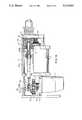
- FIG. 1shows an axial section of a device according to the invention which is embodied as an electrical hand tool.
- FIG. 2shows a tension-deflection characteristic of an elastic member proposed according to the invention.
- FIG. 3shows an axial section corresponding to FIG. 1 of a part of the device on an enlarged scale.
- FIG. 4shows a cross section view according to line IV--IV in FIG. 3.
- FIGS. 5a and 5bshow a cross section corresponding to FIG. 3 of two versions of a part of the device on an enlarged scale.
- FIG. 6shows a cross section view according to the line VI--IV in FIG. 5a.
- FIG. 7shows a cross section corresponding to FIG. 3 of a fourth version of a part of the device on an enlarged scale.
- FIG. 8shows a cross section view according to the line VIII--VIII in FIG. 7.
- FIG. 9shows a longitudinal section of a part of the device of FIG. 1 according to a fifth version on an enlarged scale.
- FIG. 10shows a cross section corresponding to FIG. 9 of a part of the device according to a sixth version, however with portions of the housing of the device shown cut away.
- FIG. 11shows a longitudinal section corresponding to FIG. 9 according to a seventh version of the device according to the invention.
- FIG. 12shows a cross section according to the line XII--XII in FIG. 11.
- FIG. 13shows a longitudinal section corresponding to FIG. 11 of a part of the device on an enlarged scale, in which a different tool holding means is shown.
- FIG. 14shows a cross section corresponding to FIG. 1, in which the air intake and outlet openings are disposed differently in the housing in order to achieve a different cooling air flow.
- FIG. 15shows a view of the front part of an electric hand tool provided with dust removal means suited to a device from FIG. 14.
- FIG. 16shows an axial cross section corresponding to FIG. 1 of an electric hand tool according to an eighth version having two drive motors.
- FIG. 17shows a top view of a part of the device of FIG. 16 according to the line XVII--XVII.
- Reference number 1indicates the housing of an electric drilling tool which comprises in the usual way an electric motor 2, for instance the collector type, and also cooperating with the drive shaft 3 is transmission 4 in the form of a double gear wheel drive and a tool spindle 5.
- a tool(not shown) can be fastened at the free end of the tool spindle 5 in arbitrary manner.
- a percussion body 6At the opposite inner end of the tool spindle 5 an extension thereof there is included a percussion body 6 which is movable through slide bearings 7 to and fro in the housing 1 in a freely slidable way.
- the driving of the percussion body 6 for engendering reciprocating movement thereofis possible by means of a driving body 8 with an associated elastic member 9, whereof the construction and the operation will be further elucidated hereinbelow.
- the housingis provided with a handgrip 10 in which a switch 11 is mounted for the empowerment and switching off of the electric motor 2.
- a switch 11is mounted for the empowerment and switching off of the electric motor 2.
- the operation and the function of the switch 11forms no part of the invention and is assumed known, as is equally the principal operation of the electric motor 2 for driving the tool spindle 5 through the transmission 4.
- drive member 8On the intermediate shaft 12 of the transmission, drive member 8 is supported, the manner of support being modified according to the embodiment of drive member 8.
- Drive member 8can extend a fixed angle deviating from 90 degrees with respect to the center line of intermediate shaft 12, this and other matters being so arranged that elastic member 9, in the form of a plate to be described in further detail hereinbelow, similarly extends an angle deviating from 90 degrees to the center line of intermediate shaft 12.
- elastic member 9in the form of a plate to be described in further detail hereinbelow, similarly extends an angle deviating from 90 degrees to the center line of intermediate shaft 12.
- plate 9is mounted rotatably on drive member 8, so that plate 9 undergoes an exclusively reciprocating motion, while drive member 8 rotates together with shaft 12.
- the connection between drive member 8 and shaft 12is brought about via an axial claw coupling, whereof member 13 is fixed firmly to drive member 8, and member 14 is slidable with a sleeve 15.
- Sleeve 15has a passage opening with internal toothing 16, which cooperates with toothing 17 on shaft 12, which toothing 17 engages with gear wheel 18 of tool spindle 5.
- shaft 12is provided with a shoulder 18, compression spring 19 being held between shoulder 18 and sleeve 15.
- tool spindle 5is mounted to a certain extent axially slidably in the bearing of the housing, so that on the impression of tool spindles in the direction of arrow P1, gear wheel 18 is carried therewith to the right, which slides sleeve 15 along to the right and causes member 14 of the dog clutch to engage with member 13 and thus with drive member 8.
- the elastic plate-shaped member 9has a bushing through which percussion body 6 is freely movably housed, whereby it is to be understood that body 6 displays a notch 20 at the level of the plate Into this notch projects tongue 21 of plate 9 (see FIG. 4), this and other matters being so arranged that on reciprocating motion of plate 9 from position A to position B, and vice versa, tongue 21 thrusts against the end faces of notch 20, through which percussion body 6 is carried in a retarded manner along with the motion of plate 9.
- the dimensioning of the stroke of plate 9is such that percussion body 6 repeatedly hits against the free end of tool spindle 5, whereby a hammering effect results.
- a non-linear spring characteristicis obtained simply by adopting a relatively stiff plate as the elastic member 9.
- the second elastic plate 26(see also FIGS. 3 and 4) has a more pliant spring characteristic and therefore a lower spring constant than plate 9.
- the spring characteristic indicated by lines 24" and 25"will, for example, be followed until plate 9 cooperates.
- the lines 24" and 25"intersect the S axis at points C and D.
- the distance CDis the clearance between the spring systems and notch 20 of percussion body 6.
- a construction of the kindwill at least cause the sharp angle between the segments BA and 24 to take a smoother course, as is indicated by-line segment 27. If there is also a second spring plate 26 arranged to the right side of plate 9, this smoothedcourse can equally be brought about on the left-hand side of the vertical axis of the system in FIG. 2 according to line 27.
- the embodiment according to FIG. 3departs from that in FIG. 1 insofar as that dog clutch 13 and 14 is omitted in this instance.
- the drive body 8is shaped here in the form of a rounded rectangular shoulder with respect to shaft 12 tiltable bush, which is clasped firmly mounted collar 28 between a on shaft 12 with an oblique thrust surface 29 and a freely slidable sleeve 30 with respect to shaft 12, also with an oblique thrust surface 31.
- the thrust surfaces 28 and 31lie mutually parallel to each other.
- the sleeve 30,is in the manner described hereinabove according to FIG. 1, and is similarly moveable toward the right by gear wheel 18 in opposition to the pressure of compression spring 15.
- the gear wheel 18is moved toward the right, the thrust surfaces 29 and 31 will hence be moved toward each other, so that drive member 8 is set into a position deviating from 90 degrees with respect to shaft 12.
- the elastic plate 9will similarly be made to incline in a position between the extremes A, B in FIG. 1.
- plate 9is mounted with respect to drive member 8 by means of a radial ball bearing 32. To that end plate 9 is fastened between two normal spring washers 33 on the outer ring of the ball bearing housing 32. In a corresponding way, an optional spring plate 26 is mounted.
- FIGS. 5a, 5b and 6show an alternative embodiment of the driving mechanism for the percussion body 6. Identical components are indicated by the same reference numerals.
- spring plate 9as an elastic body.
- a second spring plate 26is not used here, but plate 2b is executed with a circuitous-shaped or meandering tongue 35, of which there are two arranged on each opposing side of plate 9, such that a lower spring constant is brought about.
- the extremity of the tongueagain projects into notch 20 in percussion body 6.
- the plate 9is here too clamped between two spring washers 33 on the outer race of a radial ball bearing.
- the radial ball bearingis fastened to drive body 8, which is arranged tiltably with respect to intermediate shaft 12.
- the drive body 8is tilted by means of a sliding bushing 15, which is now provided with a radially directed steering surface 31', which cooperates with a radially inward facing steering surface 36 of driving member 8.
- a sliding bushing 15Through the movement of bushing 15 toward the right against the pressure of a compression spring, steering surface 31 will come into contact with steering surface 35 and cause member 8 to tilt.
- this plate 9acquires an angle deviating from 90 degrees with respect to intermediate shaft 12 and plate 9 can rock to and fro between the two extreme positions A and B in the manner described above.
- the extremities of the tongues 35will deflect out of the plane of plate 9, through which a lower spring constant results. Hence the line 24'/25' in FIG. 2 can be achieved.
- FIG. 5bdeparts from the embodiment according to FIG. 5a with respect to the mounting of plate 9 in relation to drive member 8.
- useis not made of the radial ball bearing 32, but of an axial thrust bearing 37, whereby each ball bearing 39 is mounted between plate 9 and on the one side an axial wall member 40 of drive member 8 and on the other side, ring 41.
- the ring 41is mounted on a reduced portion of the drive member 8 by means of a spring washer 42.
- the drive memberis here, similarly corresponding to FIG. 5a, tiltable by means of sleeve 15, which is slidable to the right.
- FIGS. 7 and 8show that the elastic member in the form of a stiff plate 9 cooperates with a specially shaped spring plate 26, which is made more pliable in comparison to the spring plate in FIG. 4. Through this sharper transitions results at the points A and B of the spring tension-deflection characteristic in the system according to FIG. 2.
- drive member 8is executed with a bearing ring 43 arranged directly on the intermediate shaft, around which ring a second bearing ring 44 is mounted whereof the outer surface displays portion 45, whereof the center line forms an angle with that of the drilled hole in the shell 43.
- a radial ball bearing 32 arranged on this outer surface 35can adopt an oblique position with respect to the intermediate shaft 12, and the spring plate 9 which is mounted in the manner according to FIG. 5a.
- the clutch between intermediate shaft 12 and drive body 8is absent.
- the hammering operation of percussion body 6can be inactivated by fixing this body in the drawn position, for example by passing a pin 6' through a hole in the slide bearing 7 into the percussion body 6.
- FIG. 9shows an embodiment in which percussion body 6 is not accommodated in a sliding support in housing 1 but is suspended in two parallel spring plates 46.
- the lower end of each plate 46is fastened in a support 47 of the housing 1.
- the free upper end of each plate 46is firmly secured to percussion body 6.
- a displacement of percussion body 6 to the right or to the left respectively in FIG. 9,results in a translation of percussion body 6, one of the end positions being drawn in the FIG. 9, in this instance in contact with the free end of tool shaft 5.
- percussion body 6is not made with a notch but with two projections 20' which are arranged at a distance from each other. In the space between the projections 20', a tongue 21 of plate 9 can project.
- the plateis provided on both sides with a spring plate 26. It is clear that the forms of both plate 9 and of plate 26 may correspond to the plate forms described above and shown in the preceding figures. The mounting of the plates 9 and 26 respectively can take place in the same way as in the various other embodiments.
- shaft 12 for drive body 8is not coupled to the drive shaft of motor 2 by means of a first transmission, but through a tongue and groove coupling 40, so that shaft 12 has the same rotation speed as the motor shaft 12.
- the couplingis located at the position of the first motor bearing 49, this and other details being such that assembly or disassembly of the motor 2 can take place without it being necessary to dismantle shaft 12.
- FIG. 10shows an embodiment in which percussion body 6 is guided in an axial blind drilled hole 50 in the tool spindle.
- the end of percussion body 6 projecting outside the drilled hole 50displays notch 20, into which tongue 21 of spring plate 9 projects
- the spring plateis turned over at a central portion 21 to form sleeve 51 in which groove 52 is arranged.
- a ball cage 53can be accommodated which similarly runs in a sloping ball track 54 of the drive body 8.
- the drive body 8is mounted directly onto the shaft 3 coming from the motor 2 by means of two radial ball bearings 55 separated by a mutual distance.
- the motor shaft 3is made with a toothed end portion 17 which cooperates with the gear wheel 18.
- the toothed portion 17similarly engages with the slidable clutch member 14 of a dog clutch which cooperates with a clutch member 13 of drive member 8.
- the part 14 of dog clutchcan be moved to the right or to the left respectively by any arbitrary means, for example by a separate actuation means 55, in order to bring about the coupling between shaft 3 and drive member 8.
- a slip coupling in the form of a ball clutchis arranged between gear wheel 18 and tool spindle 5.
- the gear wheel 18is mounted freely rotatable on tool spindle 5 between two fixed rings, 56 and 57 respectively.
- a slidable ring 58can be pushed, owing to axial splines on the outside of tool spindle 5 and on the inside of ring 58 respectively, in the direction of the left side face of gear wheel 18 by means of a packet of cupped spring washers 59 which abut against the ring 57.
- held in gear wheel 18are balls 60 which are each pressed by ring 58 into one chamber of gear wheel 18.
- the ringis provided with ball-receiving pits.
- FIGS. 11 and 12show a following embodiment in which the rotating drive of a tool can be inactivated while the percussion mechanism remains in operation.
- spindle 5is provided with a portion 60 with external splines, upon which is arranged a slidable ring with internal splines 61.
- ring 61is slidable in an axial direction with respect to spindle 5, but remains non-rotatable in respect thereof
- dowels 62On the side facing gear wheel 18 ring 61 is provided with dowels 62, which can engage with recesses in the side face of gear wheel 18. When the dowels 62 fall into these recesses, gear wheel 18 is non-rotatable with respect to ring 61.
- a compression springis held between a wall member 63 of the housing 1 and ring 61.
- a hand-operable rotary knobwhich is turnable around a vertical axis.
- pin 66which projects into an annular groove of ring 61.
- pin 66will move to the right in FIG. 11, taking with it ring 61 in opposition to the pressure of compression spring 64. In that position the dowels 62 come to lie free of gear wheel 18, whence gear wheel 18 is freely rotatable with respect to ring 61 and hence freely rotatable with respect to tool spindle 5.
- knob 65may be turned around, through which ring 61 is moved to the right and the coupling between ring 61 and gear wheel 18 does not occur even when tool spindle 5 is impressed to the right.
- the rotary motion of intermediate shaft 12is translated only into a driving of drive member 8 and the reciprocating motion of plate 9 and thus of percussion body 6.
- the gear wheel 18revolves thereby freely on tool spindle 5 and tool spindle 5 will exert exclusively a hammering effect.
- notch 20 in percussion body 6is located on the underside or on the side facing the intermediate shaft 12, so that plate 9 extends exclusively on the underside of percussion body 6.
- two spring plates 26 and 26'are arranged next to plate 9, a U-shaped fissure 68 being arranged for greater elasticity in one or both plates, whereby the spring length is increased.
- Thismay be with the known drill receiving device, which is screwed onto a screw thread of tool spindle 5.
- This holder deviceconsists of a central part 70, around which a threaded part 71 is mounted. At the front of central part 70 and inside threaded part 71, wedge shaped jaws 72 are placed, whereof the inward facing parts 73 fall into recesses in the shank of the drill-bit G.
- the length of the parts 73is less than the length of the recess in the drill-bit G, so that the drill-bit can undergo a certain axial movement with respect to the receiving apparatus, while nonetheless a rotary motion can be transmitted. In this way it is possible to mount the end face of the drill shank G directly against the end face of tool spindles, so that the percussive energy is delivered from the percussion body 6 via tool spindle 5 directly to the drill-bit G.
- FIG. 13An alternative embodiment of the holder head is shown in FIG. 13, in which the portion of tool spindle 15 protruding form housing 1 is executed with regularly around the circumference hollowed out parts 75, into which roller bodies 76 fit. These lie enclosed (in both the axial and in the radial sense) in the recesses 75.
- Tool spindle end 5also carries a sleeve-like housing 76' with recesses 77 similarly for the receiving of the roller bodies 76.
- the length of sleeve-like housing 76'is such that this can accommodate the shank end of the drill-bit G.
- This shank endis also made with recesses 78 for the accepting of roller bodies 79.
- the length of recess 78is however here greater than that of the bodies 79, so that an axial movement of the shank G with respect to roller bodies 79 is possible, but not a radial movement.
- the roller bodies 79fit analogously to the bodies 75 into chambers 80 of sleeve 76 .
- the bodies 75 and 79respectively are held in their places by the appropriate rings 81 and 82 respectively which are mounted slidably on the outside of the sleeve 76'.
- a compression spring 83which on the one hand ensures that ring 81 rests against a shoulder 84 of sleeve 76' and on the other hand ensures that ring 82 rests against the end face of a collar 85 mounted firmly on sleeve 76'.
- the collar 85is, for instance, made of plastic material.
- the latteris provided with a groove-shaped recess 86 in which a thickened edge 87 of the collar locks grippingly.
- the sleeve 76' with the members supported therebycan be removed from the end of tool spindle 5 by sliding ring 81 to the left in opposition to the pressure of the compression spring 83, whence the roller bodies 76 can be moved out of the recesses 75, whereafter sleeve 76' can be removed.
- the refittingtakes place in reverse manner.
- the shank of drill-bit Gcan be fitted in a similar way by sliding ring 82 to the right in opposition to the pressure of spring 83.
- protection ring 82may also be provided with a skirt part 88 extending over the compression spring 83 and partly over ring 81.
- the percussion mechanismis cooled, to which end a motor housing 1 is normally provided with cooling are openings (see FIG. 1).
- the cooling airis passed forcibly along the percussion mechanism and that use is thereby made of the blade wheel 90 already present on electric motor 2.
- This twin blade wheel 90serves for the usual cooling of the electric motor 2, but now also, after the making of appropriately disposed passage openings in the motor housing 1, for the creation of a cooling air stream along the percussion mechanism.
- a passage opening 92behind which a filter 93 is situated.
- a passage opening 94there is made beneath the motor bearing a passage opening 94 (see FIG.
- FIG. 14shows a different configuration, in which on the underside of the housing 1 there is placed an intake opening 97. Owing to this opening 97, it is possible to carry the air stream via the percussion mechanism and passage opening 92, directly to motor 2 and to discharge the air stream through an outlet opening 95. In this embodiment passage opening 94 is absent.
- the opening 97is excellently suited for the attachment of a flexible tube or conduit, as is shown in FIG. 15.
- This flexible tube 98is connected to a cylindrical auxiliary handgrip 100 which is fastened in the usual way by means of a mounting ring to the housing 1.
- the handgrip 100is made hollow and thus defines a cavity for receiving a filter or dust bag 101, which is arranged freely inside the handgrip.
- the cylindrical filter 101is in coaxial and spaced relationship with the wall of the handle 100 thus defining an annular filtered air chamber.
- the dust bagextends from bottom to top and is firmly mounted on the central intake opening 102 inside the handgrip, which stands in connection with a second flexible tube 103.
- This flexible tubeleads to a drill foot 104, which may be joined in known fashion with the handgrip through rod 105. Dust produced by drilling can be led through the hollow drill foot 104 and the tube 103 into the dust bag 101, the air stream being engendered by the fan 90 of the electric motor.
- FIGS. 16 and 17show an embodiment in which the hammer and rotary drilling apparatus is provided with two driving motors 2 and 2', whereof motor 2 serves for the bringing into rotation of tool spindle 5 by way of transmission 110.
- Tool spindle 5is mounted in a bushing 111 which is rotatably held by rolling bearings 112 in housing 1 of the machine.
- the bushing 111is provided with gear wheel 18 which cooperates with the pinion of the shaft of motor 2.
- the bushing 111moreover accommodates percussion body 6, such that the end face of percussion body 6 can come into contact with the end face of tool spindle 5.
- the motor 2'serves for the driving of a percussion body, to which end the motor drives via a first transmission 113, an intermediate shaft 12 which is mounted by means of rolling bearing 114 in the housing 1.
- the side of transmission 113 remote from the intermediate shaft 12is provided with concentric disc 115, concentric pin 116 being mounted by means of rolling bearing 117 in drive member 118.
- the drive memberhas in top view a triangular form (see FIG. 17) and is so positioned that the top angle of the triangle is disposed towards percussion body 6.
- an elastic member 9in the form of a strip spring 119 to the drive member 118 which can take place in arbitrary fashion, for example using screws 120.
- each strip springis similarly fastened to a triangular body 121, of which the form corresponds to that of drive member 118.
- the fasteningsimilarly takes place by means of screws 120.
- the triangular member 121is provided with pin 122, onto which a fork-shaped end part 123 of percussion member 6 grips rotatably.
- a transverse guide member 124is also coupled to pin 122, which member is slidably conducted along parallel guide bars 125. The bars are firmly mounted in housing 1.
- drive member 118is mounted rotatably around a motor shaft or a shaft cooperating therewith, which drive member so loads a pair of elastic members 119 that on the actuation of motor 2' and as a consequence of concentric members 115 and 116, the distance between the members 118 and 121 is repeatedly enlarged and reduced.
- Thiscauses a flexing of flexible members 119, which members uncoil against the flanks of triangular members 118 and 121, which results in a non-linear spring characteristic.
- the percussion body 6, which is held freely slidable in housing 1,follows the reciprocating motion of drive member 118 in a delayed manner, such that the strip springs 119 are stretched to a greater or lesser extent.
- the percussion body 6thereby repeatedly reaches the end face of tool spindle 5, which can be bought into rotation by the empowerment of motor 2.
- the above described devicecan therefore have three functions, namely rotary drilling only, hammering only or a combination of hammer and rotary drilling. In the last case the full power of the two motors can be utilized, which results in a doubling of the power in comparison to the other embodiments.
Landscapes
- Engineering & Computer Science (AREA)
- Mechanical Engineering (AREA)
- Percussive Tools And Related Accessories (AREA)
- Drilling And Boring (AREA)
- Drilling Tools (AREA)
- Earth Drilling (AREA)
- Drilling And Exploitation, And Mining Machines And Methods (AREA)
Abstract
Description
Claims (3)
Applications Claiming Priority (2)
| Application Number | Priority Date | Filing Date | Title |
|---|---|---|---|
| NL8801466 | 1988-06-07 | ||
| NL8801466ANL8801466A (en) | 1988-06-07 | 1988-06-07 | DEVICE FOR DRIVING A DRILL AND / OR IMPACT TOOL. |
Related Parent Applications (1)
| Application Number | Title | Priority Date | Filing Date |
|---|---|---|---|
| US07/360,316DivisionUS5052497A (en) | 1988-06-07 | 1989-06-02 | Apparatus for driving a drilling or percussion tool |
Publications (1)
| Publication Number | Publication Date |
|---|---|
| US5113951Atrue US5113951A (en) | 1992-05-19 |
Family
ID=19852426
Family Applications (2)
| Application Number | Title | Priority Date | Filing Date |
|---|---|---|---|
| US07/360,316CeasedUS5052497A (en) | 1988-06-07 | 1989-06-02 | Apparatus for driving a drilling or percussion tool |
| US07/713,410Expired - LifetimeUS5113951A (en) | 1988-06-07 | 1991-06-11 | Apparatus for driving a drilling or percussion tool |
Family Applications Before (1)
| Application Number | Title | Priority Date | Filing Date |
|---|---|---|---|
| US07/360,316CeasedUS5052497A (en) | 1988-06-07 | 1989-06-02 | Apparatus for driving a drilling or percussion tool |
Country Status (9)
| Country | Link |
|---|---|
| US (2) | US5052497A (en) |
| EP (1) | EP0345896B1 (en) |
| JP (1) | JP2655282B2 (en) |
| AT (1) | ATE111796T1 (en) |
| AU (1) | AU620403B2 (en) |
| CA (1) | CA1326380C (en) |
| DE (1) | DE68918335T2 (en) |
| ES (1) | ES2059705T3 (en) |
| NL (1) | NL8801466A (en) |
Cited By (68)
| Publication number | Priority date | Publication date | Assignee | Title |
|---|---|---|---|---|
| DE4342484A1 (en)* | 1993-12-13 | 1995-04-06 | Siemens Nixdorf Inf Syst | Hand drill |
| US5467835A (en)* | 1993-10-18 | 1995-11-21 | Hilti Aktiengesellschaft | Drilling or chiseling tool with suction apparatus |
| US5566458A (en)* | 1994-12-13 | 1996-10-22 | Milwaukee Electric Tool Corporation | Clutch mechanism for reciprocating saws |
| US5607023A (en)* | 1994-12-13 | 1997-03-04 | Milwaukee Electric Tool Corp. | Impact absorption mechanism for power tools |
| US5688082A (en)* | 1995-01-19 | 1997-11-18 | Richardson; Owen Lewis | Dust extractor |
| US5690184A (en)* | 1995-04-20 | 1997-11-25 | Fujita Corporation | Rock drilling apparatus |
| US5689891A (en)* | 1994-12-13 | 1997-11-25 | Milwaukee Electric Tool Corp. | Clutch mechanism for reciprocating saws |
| US5904453A (en)* | 1997-12-17 | 1999-05-18 | Gavia; Cesar | Drill and vacuum combination |
| US5919010A (en)* | 1998-05-08 | 1999-07-06 | Fonseca; Roberto | Apparatus for forming inspection openings in asbestos insulation cladding |
| US5933969A (en)* | 1995-09-26 | 1999-08-10 | Skil Europe B.V. | Circular saw |
| US6039038A (en)* | 1997-02-03 | 2000-03-21 | Robert Bosch Gmbh | Drilling assisting device for hand-guided drill |
| USRE37211E1 (en) | 1994-12-13 | 2001-06-12 | Milwaukee Electric Tool Corporation | Clutch mechanism for reciprocating saws |
| DE10053582A1 (en)* | 2000-10-28 | 2002-05-16 | Bosch Gmbh Robert | Hand tool with a dust extraction device |
| US20020141836A1 (en)* | 2001-03-27 | 2002-10-03 | Manfred Ege | Dust removal unit for a hand tool device |
| US6615930B2 (en)* | 2001-03-14 | 2003-09-09 | Hilti Aktiengesellschaft | Suction module |
| US20030190877A1 (en)* | 2002-01-10 | 2003-10-09 | William Gallagher | Angle grinder |
| US6666286B2 (en)* | 2001-12-20 | 2003-12-23 | Goei Co., Ltd. | Fluid circulating apparatus for drill |
| US20040002296A1 (en)* | 2001-09-11 | 2004-01-01 | Doris Reich | Hand machine-tool comprising a dust extraction device |
| US20040011543A1 (en)* | 2002-07-17 | 2004-01-22 | Ohio State Home Services | Dust suppression guard |
| US20040157541A1 (en)* | 2001-06-29 | 2004-08-12 | Dieter Wendt | Protective device for a hand machine tool |
| US20040192184A1 (en)* | 2003-03-13 | 2004-09-30 | Ernst Staas | Dust extration shroud for a power tool |
| US20040226969A1 (en)* | 2003-05-15 | 2004-11-18 | Shew Jerry D. | Grease gun |
| US20040226272A1 (en)* | 2003-05-14 | 2004-11-18 | Guido Valentini | Motorized tool with suction and dust collection capacity |
| US20040231871A1 (en)* | 2003-03-21 | 2004-11-25 | Klaus-Dieter Arich | Hand held drilling and/or hammering tool with dust collection unit |
| US20040247407A1 (en)* | 2003-06-09 | 2004-12-09 | Python Perfect Cutter, Inc. | Hole cutting tool |
| USD499625S1 (en) | 2003-03-28 | 2004-12-14 | Black & Decker, Inc. | Shroud for a dust extractor |
| US20040251041A1 (en)* | 2003-03-21 | 2004-12-16 | Horst Grossman | Cordless hand held power tool with powered accessory |
| USD499946S1 (en) | 2003-03-28 | 2004-12-21 | Black & Decker Inc. | Dust extractor |
| US20050089380A1 (en)* | 2003-09-12 | 2005-04-28 | Thorsten Stoerig | Suction device |
| US20050247463A1 (en)* | 2002-11-25 | 2005-11-10 | Robert Bosch Gmbh | Hand-held machine tool comprising a dust box |
| US20050281627A1 (en)* | 2004-06-16 | 2005-12-22 | Rory Britz | Hand-held power tool with a dust suction module |
| US20050286983A1 (en)* | 2004-05-26 | 2005-12-29 | Airbus France | Drilling device and drilling method used with such a device |
| US20060091159A1 (en)* | 2004-10-28 | 2006-05-04 | Shew Jerry D | Grease gun |
| US20060110228A1 (en)* | 2002-09-27 | 2006-05-25 | Jonas Hansson | Assembly for removing chips from a cutting work area of a cutting tool |
| US20060153650A1 (en)* | 2003-10-06 | 2006-07-13 | Robert Simm | Suctioning device for a machine tool |
| US20060272123A1 (en)* | 2005-05-19 | 2006-12-07 | Aldo Di Nicolantonio | Dust catcher |
| US20070251199A1 (en)* | 2006-04-24 | 2007-11-01 | Guido Valentini | Dust collection container with bladed element for power tool with suction capacity |
| US20070292222A1 (en)* | 2006-05-26 | 2007-12-20 | Colon Julio A | Drill bit and dust collector attachment for drills |
| US20080202781A1 (en)* | 2007-02-23 | 2008-08-28 | Tomomasa Nishikawa | Drilling device |
| US20090007986A1 (en)* | 2007-07-06 | 2009-01-08 | Freddy Lin | Pneumatic tool with dust-blowing effect |
| USD593389S1 (en)* | 2008-06-10 | 2009-06-02 | Brad Smythe Clayton | Dust shroud |
| US20090172911A1 (en)* | 2005-01-12 | 2009-07-09 | Kabushiki Kaisha Miyanaga | Drill Dust Collector |
| US20090193614A1 (en)* | 2008-02-06 | 2009-08-06 | Moore Carl P | Dust collection apparatus for demolition tool |
| US7717191B2 (en) | 2007-11-21 | 2010-05-18 | Black & Decker Inc. | Multi-mode hammer drill with shift lock |
| US7717192B2 (en) | 2007-11-21 | 2010-05-18 | Black & Decker Inc. | Multi-mode drill with mode collar |
| US7735575B2 (en) | 2007-11-21 | 2010-06-15 | Black & Decker Inc. | Hammer drill with hard hammer support structure |
| US20100155095A1 (en)* | 2008-12-19 | 2010-06-24 | Makita Corporation | Power tool |
| US7762349B2 (en) | 2007-11-21 | 2010-07-27 | Black & Decker Inc. | Multi-speed drill and transmission with low gear only clutch |
| US7770660B2 (en) | 2007-11-21 | 2010-08-10 | Black & Decker Inc. | Mid-handle drill construction and assembly process |
| US7798245B2 (en) | 2007-11-21 | 2010-09-21 | Black & Decker Inc. | Multi-mode drill with an electronic switching arrangement |
| US7854274B2 (en) | 2007-11-21 | 2010-12-21 | Black & Decker Inc. | Multi-mode drill and transmission sub-assembly including a gear case cover supporting biasing |
| US20110194796A1 (en)* | 2010-02-05 | 2011-08-11 | Schaeffler Technologies Gmbh & Co. Kg | Angled Bore Bearing |
| US20110239398A1 (en)* | 2010-04-05 | 2011-10-06 | Makita Corporation | Dust collecting devices |
| US20130055523A1 (en)* | 2011-09-07 | 2013-03-07 | Makita Corporation | Power tool dust collecting device and power tool |
| US20130213681A1 (en)* | 2010-07-08 | 2013-08-22 | Makita Corporation | Dust collecting device and impact tool |
| US20140138114A1 (en)* | 2012-11-19 | 2014-05-22 | Makita Corporation | Dust collecting device and power tool having the same |
| USD725981S1 (en) | 2013-10-29 | 2015-04-07 | Black & Decker Inc. | Screwdriver with nosepiece |
| US9318932B2 (en) | 2010-06-14 | 2016-04-19 | Black & Decker Inc. | Control unit for a power tool |
| US20160129540A1 (en)* | 2014-11-12 | 2016-05-12 | Robert Bosch Gmbh | Hand-Held Power-Tool Device |
| US9901974B2 (en) | 2014-05-13 | 2018-02-27 | Deprag Schulz Gmbh U. Co. | Method for direct screwing of structural components, in particular for flow hole screwing and device for direct screwing of structural components |
| US10238252B2 (en) | 2014-05-15 | 2019-03-26 | Christopher Joseph Buczek | Dust collector for a drill press or system |
| US10286529B2 (en) | 2013-06-27 | 2019-05-14 | Makita Corporation | Screw-tightening power tool |
| US10821594B2 (en) | 2013-10-29 | 2020-11-03 | Black & Decker Inc. | Power tool with ergonomic handgrip |
| US11103988B2 (en)* | 2017-11-06 | 2021-08-31 | CJ&S, Inc. | Jack hammer silica dust suppression system |
| US20240025026A1 (en)* | 2022-07-19 | 2024-01-25 | Robert Bosch Gmbh | Machine Tool Apparatus, Machine Tool, and Method of Operating a Machine Tool |
| USD1034130S1 (en)* | 2022-02-07 | 2024-07-09 | Robert Bosch Gmbh | Suction attachment for a power tool |
| US12233523B2 (en) | 2020-12-07 | 2025-02-25 | Black & Decker Inc. | Power tool with multiple modes of operation and ergonomic handgrip |
| USD1064773S1 (en) | 2021-12-03 | 2025-03-04 | Robert Bosch Gmbh | Hammer drill |
Families Citing this family (53)
| Publication number | Priority date | Publication date | Assignee | Title |
|---|---|---|---|---|
| DE4121279A1 (en)* | 1991-06-27 | 1993-01-07 | Bosch Gmbh Robert | DRILL AND / OR SLOPE |
| US5320177A (en)* | 1992-03-30 | 1994-06-14 | Makita Corporation | Power driven hammer drill |
| DE4231986A1 (en)* | 1992-09-24 | 1994-03-31 | Bosch Gmbh Robert | Hammer and / or percussion hammer |
| ES2134120B1 (en)* | 1996-10-03 | 2000-05-01 | Martin Felix Alvarez | DRILL-VACUUM CLEANER. |
| DE19717712A1 (en)* | 1997-04-18 | 1998-10-22 | Black & Decker Inc | Hammer drill |
| DE19839963A1 (en)* | 1998-09-02 | 2000-03-09 | Hilti Ag | Power tool |
| DE19851888C1 (en)* | 1998-11-11 | 2000-07-13 | Metabowerke Kg | Hammer drill |
| JP2000153473A (en)* | 1998-11-19 | 2000-06-06 | Makita Corp | Hammering tool |
| DE10030962C2 (en)* | 2000-06-24 | 2002-06-20 | Hilti Ag | Electric hand tool device with striking mechanism |
| DE10149216A1 (en) | 2001-10-05 | 2003-04-24 | Bosch Gmbh Robert | Hand-held machine tool e.g. hammer drills etc. ha impact tool driver unit with am element consists of two cam track parts acting in two different axial directions of an intermediate shaft |
| DE50112450D1 (en)* | 2001-10-15 | 2007-06-14 | Hilti Ag | Cooling air duct for an electric hand tool with electro-pneumatic impact mechanism |
| GB2385017B (en)* | 2002-02-08 | 2005-06-29 | Black & Decker Inc | Drilling and/or hammering tool |
| DE20206243U1 (en)* | 2002-04-19 | 2003-08-28 | Bulka, Thorsten, 63674 Altenstadt | Cutting unit for cutting glass or ceramic materials has a rotating axle and a rotating shaft which is movable along the horizontal direction |
| DE10242414A1 (en)* | 2002-09-12 | 2004-03-25 | Hilti Ag | Power tool with blower |
| GB2396130B (en)* | 2002-12-10 | 2005-09-28 | Black & Decker Inc | Apparatus for producing self-exciting hammer action, and rotary power tool incorporating such apparatus |
| EP1634359B1 (en) | 2003-06-17 | 2013-12-04 | Black & Decker Inc. | Generator having dual path airflow cooling arrangement and method therefor |
| EP1682297A4 (en)* | 2003-10-28 | 2009-11-11 | Ibex Ind Ltd | Powered hand tool |
| JP4557555B2 (en)* | 2004-01-08 | 2010-10-06 | 株式会社マキタ | Electric tool |
| DE102004026845A1 (en)* | 2004-06-02 | 2005-12-22 | Robert Bosch Gmbh | Hand tool, in particular drill and / or percussion hammer |
| DE102004058696A1 (en)* | 2004-12-06 | 2006-06-08 | Hilti Ag | Electric power tool |
| EP1674213B1 (en)* | 2004-12-23 | 2008-10-01 | BLACK & DECKER INC. | Power tool cooling |
| ATE396841T1 (en)* | 2004-12-23 | 2008-06-15 | Black & Decker Inc | POWER TOOL HOUSING |
| EP1674211A1 (en)* | 2004-12-23 | 2006-06-28 | BLACK & DECKER INC. | Power tool housing |
| GB2423050A (en)* | 2005-02-10 | 2006-08-16 | Black & Decker Inc | Hammer with ramps causing pivotal oscillation |
| DE102005007546A1 (en)* | 2005-02-18 | 2006-08-24 | Robert Bosch Gmbh | Power tool |
| DE102005037535A1 (en)* | 2005-08-09 | 2007-02-15 | Robert Bosch Gmbh | Extraction system of a power tool and power tool with a suction system |
| DE102005062693A1 (en)* | 2005-12-28 | 2007-07-05 | Robert Bosch Gmbh | Hand tool machine e.g. triangular sander for use by handyman, has fan wheel provided for producing cooling air flow for cooling motor, where air flow sucked by fan wheel is partially guided over operating unit |
| DE102006000162A1 (en)* | 2006-04-06 | 2007-10-11 | Hilti Ag | Electric hand tool machine with internal cooling fan |
| DE102006029634A1 (en)* | 2006-06-28 | 2008-01-03 | Robert Bosch Gmbh | Electric hand tool |
| ES2544818T3 (en)* | 2007-05-01 | 2015-09-04 | Hitachi Koki Co., Ltd. | Reciprocating tool |
| JP5015653B2 (en)* | 2007-05-01 | 2012-08-29 | 株式会社マキタ | Hammer drill |
| DE102007035699A1 (en)* | 2007-07-30 | 2009-02-05 | Robert Bosch Gmbh | Hand tool |
| DE102007000524A1 (en)* | 2007-10-18 | 2009-04-23 | Hilti Aktiengesellschaft | Electric hand tool machine with engine temperature control |
| US8196674B2 (en)* | 2008-03-05 | 2012-06-12 | Makita Corporation | Impact tool |
| DE102008000687A1 (en)* | 2008-03-14 | 2009-09-17 | Robert Bosch Gmbh | Hand tool for impact driven tools |
| DE102008000677A1 (en)* | 2008-03-14 | 2009-09-17 | Robert Bosch Gmbh | Hand tool for impact driven tools |
| US20090321101A1 (en)* | 2008-06-26 | 2009-12-31 | Makita Corporation | Power tool |
| DE102009027440A1 (en)* | 2009-07-03 | 2011-01-05 | Robert Bosch Gmbh | Hand tool |
| DE202010012253U1 (en)* | 2010-09-07 | 2010-11-18 | Robert Bosch Gmbh | Machine tool, in particular hand tool |
| DE102010062099A1 (en)* | 2010-11-29 | 2012-05-31 | Robert Bosch Gmbh | Hammer mechanism |
| DE102010062094A1 (en)* | 2010-11-29 | 2012-05-31 | Robert Bosch Gmbh | Hammer mechanism |
| JP2014148006A (en)* | 2013-02-01 | 2014-08-21 | Makita Corp | Electric power tool and portable circular saw |
| EP3028818A1 (en)* | 2014-12-03 | 2016-06-08 | HILTI Aktiengesellschaft | Power tool |
| US10328560B2 (en) | 2015-02-23 | 2019-06-25 | Brian Romagnoli | Multi-mode drive mechanisms and tools incorporating the same |
| DE202015102484U1 (en)* | 2015-05-13 | 2016-08-17 | Knoll Maschinenbau Gmbh | Single-channel minimal quantity lubrication system |
| US10493577B2 (en)* | 2016-07-21 | 2019-12-03 | Makita Corporation | Dust collection device for electric power tool, electric power tool, and dust collection system |
| EP3812102B1 (en)* | 2017-08-31 | 2023-06-07 | Dubuis et Cie | Power tools for crimping or cutting objects and methods of assembly |
| CN109419545A (en)* | 2017-08-31 | 2019-03-05 | 重庆西山科技股份有限公司 | The dynamic structure of stapler power handle |
| CN109419546B (en)* | 2017-08-31 | 2024-11-26 | 重庆西山科技股份有限公司 | Stapler power handle |
| US11298788B2 (en)* | 2018-06-19 | 2022-04-12 | Makita Corporation | Electric power tool dust collection system |
| SE1851031A1 (en)* | 2018-08-31 | 2020-03-01 | Husqvarna Ab | Power tool |
| JP7340385B2 (en)* | 2019-08-13 | 2023-09-07 | 株式会社やまびこ | electric work equipment |
| EP4008486A1 (en)* | 2020-12-04 | 2022-06-08 | Hilti Aktiengesellschaft | Machine tool with two motors |
Citations (7)
| Publication number | Priority date | Publication date | Assignee | Title |
|---|---|---|---|---|
| US1955182A (en)* | 1932-10-19 | 1934-04-17 | Hall Mfg Co | Suction device for cylinder boring machines |
| US2246916A (en)* | 1940-10-05 | 1941-06-24 | Chicago Pneumatic Tool Co | Hold-down and chip collecting attachment for drills |
| US3850254A (en)* | 1972-07-06 | 1974-11-26 | R Hirdes | Suction device for extracting drill chippings |
| US4036308A (en)* | 1974-04-09 | 1977-07-19 | Gebruder Heller Verwaltungsgesellschaft Mit Beschrankter Haftung | Apparatus for removing the drillings from the drilling site of a drill |
| US4051880A (en)* | 1976-10-29 | 1977-10-04 | The Singer Company | Dustless routers |
| DE2940362A1 (en)* | 1979-10-05 | 1981-04-16 | Licentia Patent-Verwaltungs-Gmbh, 6000 Frankfurt | Rotary and impact drill with dust extraction system - has suction members and uses electric drive motor cooling air in dust exhaust system |
| US4921375A (en)* | 1987-06-12 | 1990-05-01 | Tiziana Lenarduzzi | Antiscattering device for the collection of waste material produced in the course of drilling, milling and similar operations, to be fitted on the relevant machine tools |
Family Cites Families (17)
| Publication number | Priority date | Publication date | Assignee | Title |
|---|---|---|---|---|
| FR887738A (en)* | 1941-01-11 | 1943-11-22 | Merlin Gerin | Electric hammer and drill |
| US3511322A (en)* | 1967-09-14 | 1970-05-12 | Phillips Drill Co | Percussive hammer with vacuum system for cleaning debris from workpiece |
| DE2031357A1 (en)* | 1970-06-25 | 1971-12-30 | Neuenburg, Henry, 4300 Essen | Dust collecting device for drills, hammer drills or the like |
| US3685594A (en)* | 1970-08-03 | 1972-08-22 | Rockwell Mfg Co | Rotary hammer or the like |
| CH588632A5 (en)* | 1975-03-04 | 1977-06-15 | Bosch Gmbh Robert | Impact drill with swashplate - has spring loaded pneumatic impact piston reciprocating inside tool drive sleeve |
| DE2548100A1 (en)* | 1975-10-28 | 1977-05-12 | Bosch Gmbh Robert | MOUNTING DEVICE FOR SUCTION OF SMALL DRILLS |
| DE2917475A1 (en)* | 1979-04-30 | 1980-11-13 | Hilti Ag | DRILLING OR CHISEL HAMMER |
| US4325436A (en)* | 1980-05-21 | 1982-04-20 | Hilti Aktiengesellschaft | Hammer drill or chipping hammer device |
| DE3039669A1 (en)* | 1980-10-21 | 1982-05-27 | Robert Bosch Gmbh, 7000 Stuttgart | DRILLING HAMMER |
| DE3205141A1 (en)* | 1982-02-13 | 1983-08-18 | Robert Bosch Gmbh, 7000 Stuttgart | DRILLING HAMMER |
| DE3215198A1 (en)* | 1982-04-23 | 1983-10-27 | Friedrich Duss Maschinenfabrik GmbH & Co, 7265 Neubulach | Electro-pneumatic drilling and/or chipping hammer |
| DE3224050A1 (en)* | 1982-06-28 | 1983-12-29 | Black & Decker, Inc. (eine Gesellschaft n.d.Ges.d. Staates Delaware), 19711 Newark, Del. | Drive device for the striking mechanism of an impact or drilling hammer |
| IT1194465B (en)* | 1983-11-18 | 1988-09-22 | Ferioli Filippo Srl | MULTI-PURPOSE PORTABLE EQUIPMENT IN PARTICULAR FOR THE OPERATION OF ROTATION TOOLS IN ROTATION AND PERCUSSION AND ONLY PERCUSSION |
| NL8304043A (en)* | 1983-11-24 | 1985-06-17 | Skil Nederland Nv | DEVICE FOR DRIVING A DRILL AND / OR IMPACT TOOL. |
| JPS6018308U (en)* | 1984-06-08 | 1985-02-07 | ジューキ株式会社 | Wire stopper |
| DE3611747A1 (en)* | 1986-04-08 | 1987-10-22 | Messerschmitt Boelkow Blohm | Hand-held machine tool with suction device |
| IT8622437V0 (en)* | 1986-07-02 | 1986-07-02 | Valentini Guido | ELECTRIC MANUAL TOOL WITH MOTOR AND DUST DISCHARGE PIPE INCLUDED IN THE HANDLE. |
- 1988
- 1988-06-07NLNL8801466Apatent/NL8801466A/ennot_activeApplication Discontinuation
- 1989
- 1989-05-30AUAU35811/89Apatent/AU620403B2/ennot_activeCeased
- 1989-06-02USUS07/360,316patent/US5052497A/ennot_activeCeased
- 1989-06-05DEDE68918335Tpatent/DE68918335T2/ennot_activeExpired - Lifetime
- 1989-06-05ATAT89201437Tpatent/ATE111796T1/enactive
- 1989-06-05ESES89201437Tpatent/ES2059705T3/ennot_activeExpired - Lifetime
- 1989-06-05EPEP89201437Apatent/EP0345896B1/ennot_activeExpired - Lifetime
- 1989-06-06JPJP1142300Apatent/JP2655282B2/ennot_activeExpired - Fee Related
- 1989-06-06CACA000601890Apatent/CA1326380C/ennot_activeExpired - Fee Related
- 1991
- 1991-06-11USUS07/713,410patent/US5113951A/ennot_activeExpired - Lifetime
Patent Citations (7)
| Publication number | Priority date | Publication date | Assignee | Title |
|---|---|---|---|---|
| US1955182A (en)* | 1932-10-19 | 1934-04-17 | Hall Mfg Co | Suction device for cylinder boring machines |
| US2246916A (en)* | 1940-10-05 | 1941-06-24 | Chicago Pneumatic Tool Co | Hold-down and chip collecting attachment for drills |
| US3850254A (en)* | 1972-07-06 | 1974-11-26 | R Hirdes | Suction device for extracting drill chippings |
| US4036308A (en)* | 1974-04-09 | 1977-07-19 | Gebruder Heller Verwaltungsgesellschaft Mit Beschrankter Haftung | Apparatus for removing the drillings from the drilling site of a drill |
| US4051880A (en)* | 1976-10-29 | 1977-10-04 | The Singer Company | Dustless routers |
| DE2940362A1 (en)* | 1979-10-05 | 1981-04-16 | Licentia Patent-Verwaltungs-Gmbh, 6000 Frankfurt | Rotary and impact drill with dust extraction system - has suction members and uses electric drive motor cooling air in dust exhaust system |
| US4921375A (en)* | 1987-06-12 | 1990-05-01 | Tiziana Lenarduzzi | Antiscattering device for the collection of waste material produced in the course of drilling, milling and similar operations, to be fitted on the relevant machine tools |
Cited By (118)
| Publication number | Priority date | Publication date | Assignee | Title |
|---|---|---|---|---|
| US5467835A (en)* | 1993-10-18 | 1995-11-21 | Hilti Aktiengesellschaft | Drilling or chiseling tool with suction apparatus |
| DE4342484A1 (en)* | 1993-12-13 | 1995-04-06 | Siemens Nixdorf Inf Syst | Hand drill |
| USRE37211E1 (en) | 1994-12-13 | 2001-06-12 | Milwaukee Electric Tool Corporation | Clutch mechanism for reciprocating saws |
| US5566458A (en)* | 1994-12-13 | 1996-10-22 | Milwaukee Electric Tool Corporation | Clutch mechanism for reciprocating saws |
| US5607023A (en)* | 1994-12-13 | 1997-03-04 | Milwaukee Electric Tool Corp. | Impact absorption mechanism for power tools |
| US5689891A (en)* | 1994-12-13 | 1997-11-25 | Milwaukee Electric Tool Corp. | Clutch mechanism for reciprocating saws |
| USRE38606E1 (en)* | 1994-12-13 | 2004-10-05 | Milwaukee Electric Tool Corporation | Clutch mechanism for reciprocating saws |
| USRE37529E1 (en) | 1994-12-13 | 2002-01-29 | Milwaukee Tool Corporation | Clutch mechanism for reciprocating saws |
| US5688082A (en)* | 1995-01-19 | 1997-11-18 | Richardson; Owen Lewis | Dust extractor |
| US5690184A (en)* | 1995-04-20 | 1997-11-25 | Fujita Corporation | Rock drilling apparatus |
| US5933969A (en)* | 1995-09-26 | 1999-08-10 | Skil Europe B.V. | Circular saw |
| US6039038A (en)* | 1997-02-03 | 2000-03-21 | Robert Bosch Gmbh | Drilling assisting device for hand-guided drill |
| US5904453A (en)* | 1997-12-17 | 1999-05-18 | Gavia; Cesar | Drill and vacuum combination |
| US5919010A (en)* | 1998-05-08 | 1999-07-06 | Fonseca; Roberto | Apparatus for forming inspection openings in asbestos insulation cladding |
| DE10053582A1 (en)* | 2000-10-28 | 2002-05-16 | Bosch Gmbh Robert | Hand tool with a dust extraction device |
| US6848985B2 (en)* | 2000-10-28 | 2005-02-01 | Robert Bosch Gmbh | Hand tool comprising a dust suction device |
| US20040020671A1 (en)* | 2000-10-28 | 2004-02-05 | Justus Lamprecht | Hand tool comprising adust suction device |
| US6615930B2 (en)* | 2001-03-14 | 2003-09-09 | Hilti Aktiengesellschaft | Suction module |
| US20020141836A1 (en)* | 2001-03-27 | 2002-10-03 | Manfred Ege | Dust removal unit for a hand tool device |
| US6851898B2 (en)* | 2001-03-27 | 2005-02-08 | Hilti Aktiengesellschaft | Dust removal unit for a hand tool device |
| US6953394B2 (en) | 2001-06-29 | 2005-10-11 | Robert Bosch Gmbh | Protective device for a hand machine tool |
| US20040157541A1 (en)* | 2001-06-29 | 2004-08-12 | Dieter Wendt | Protective device for a hand machine tool |
| US20040002296A1 (en)* | 2001-09-11 | 2004-01-01 | Doris Reich | Hand machine-tool comprising a dust extraction device |
| US6910960B2 (en)* | 2001-09-13 | 2005-06-28 | Robert Bosch Gmbh | Hand machine-tool comprising a dust extraction device |
| US6666286B2 (en)* | 2001-12-20 | 2003-12-23 | Goei Co., Ltd. | Fluid circulating apparatus for drill |
| US7537065B2 (en)* | 2002-01-10 | 2009-05-26 | Black & Decker Inc. | Angle grinder |
| US20030190877A1 (en)* | 2002-01-10 | 2003-10-09 | William Gallagher | Angle grinder |
| US20040011543A1 (en)* | 2002-07-17 | 2004-01-22 | Ohio State Home Services | Dust suppression guard |
| US6830113B2 (en) | 2002-07-17 | 2004-12-14 | Ohio State Home Services | Dust suppression guard |
| US7168894B2 (en)* | 2002-09-27 | 2007-01-30 | Novator Ab | Assembly for removing chips from a cutting work area of a cutting tool |
| US20060110228A1 (en)* | 2002-09-27 | 2006-05-25 | Jonas Hansson | Assembly for removing chips from a cutting work area of a cutting tool |
| US7475739B2 (en)* | 2002-11-25 | 2009-01-13 | Robert Bosch Gmbh | Hand-held machine tool comprising a dust box |
| US20050247463A1 (en)* | 2002-11-25 | 2005-11-10 | Robert Bosch Gmbh | Hand-held machine tool comprising a dust box |
| US20040192184A1 (en)* | 2003-03-13 | 2004-09-30 | Ernst Staas | Dust extration shroud for a power tool |
| US6887146B2 (en) | 2003-03-14 | 2005-05-03 | Black & Decker Inc. | Dust extraction shroud for a power tool |
| US20040251041A1 (en)* | 2003-03-21 | 2004-12-16 | Horst Grossman | Cordless hand held power tool with powered accessory |
| US7182150B2 (en) | 2003-03-21 | 2007-02-27 | Black & Decker Inc. | Cordless hand held power tool with powered accessory |
| US20040231871A1 (en)* | 2003-03-21 | 2004-11-25 | Klaus-Dieter Arich | Hand held drilling and/or hammering tool with dust collection unit |
| US7017680B2 (en) | 2003-03-21 | 2006-03-28 | Black & Decker Inc. | Hand held drilling and/or hammering tool with dust collection unit |
| USD499625S1 (en) | 2003-03-28 | 2004-12-14 | Black & Decker, Inc. | Shroud for a dust extractor |
| USD499946S1 (en) | 2003-03-28 | 2004-12-21 | Black & Decker Inc. | Dust extractor |
| US7118609B2 (en) | 2003-05-14 | 2006-10-10 | Guido Valentini | Motorized tool with suction and dust collection capacity |
| US20040226272A1 (en)* | 2003-05-14 | 2004-11-18 | Guido Valentini | Motorized tool with suction and dust collection capacity |
| US20040226969A1 (en)* | 2003-05-15 | 2004-11-18 | Shew Jerry D. | Grease gun |
| US7523843B2 (en) | 2003-05-15 | 2009-04-28 | Alemite, Llc | Grease gun |
| US7004357B2 (en)* | 2003-05-15 | 2006-02-28 | Alemite, Llc | Grease gun |
| US20090184138A1 (en)* | 2003-05-15 | 2009-07-23 | Jerry D Shew | Grease gun |
| US20060088410A1 (en)* | 2003-05-15 | 2006-04-27 | Alemite Llc | Grease gun |
| US7997456B2 (en) | 2003-05-15 | 2011-08-16 | Alemite, Llc | Grease gun |
| AU2004241086B2 (en)* | 2003-05-15 | 2007-04-26 | Alemite Llc | Grease gun |
| US6851900B2 (en)* | 2003-06-09 | 2005-02-08 | Python Perfect Cutter, Inc. | Hole cutting tool |
| WO2004110708A3 (en)* | 2003-06-09 | 2005-11-10 | Python Perfect Cutter Inc | Hole cutting tool |
| US20040247407A1 (en)* | 2003-06-09 | 2004-12-09 | Python Perfect Cutter, Inc. | Hole cutting tool |
| US20050089380A1 (en)* | 2003-09-12 | 2005-04-28 | Thorsten Stoerig | Suction device |
| US7281886B2 (en)* | 2003-09-12 | 2007-10-16 | Hilti Aktiengesellschaft | Suction device |
| US20060153650A1 (en)* | 2003-10-06 | 2006-07-13 | Robert Simm | Suctioning device for a machine tool |
| US7425109B2 (en)* | 2003-10-06 | 2008-09-16 | Robert Bosch Gmbh | Suctioning device for a machine tool |
| US7226251B2 (en)* | 2004-05-26 | 2007-06-05 | Airbus France | Drilling device and drilling method used with such a device |
| US20050286983A1 (en)* | 2004-05-26 | 2005-12-29 | Airbus France | Drilling device and drilling method used with such a device |
| DE102004029220B4 (en)* | 2004-06-16 | 2006-03-23 | Hilti Ag | Hand tool with dust extraction module |
| DE102004029220A1 (en)* | 2004-06-16 | 2006-01-12 | Hilti Ag | Hand tool with dust extraction module |
| US7354226B2 (en)* | 2004-06-16 | 2008-04-08 | Hilti Aktiengesellschaft | Hand-held power tool with a dust suction module |
| US20050281627A1 (en)* | 2004-06-16 | 2005-12-22 | Rory Britz | Hand-held power tool with a dust suction module |
| US7249695B2 (en) | 2004-10-28 | 2007-07-31 | Alemite, Llc | Grease gun |
| US20060091159A1 (en)* | 2004-10-28 | 2006-05-04 | Shew Jerry D | Grease gun |
| US20090172911A1 (en)* | 2005-01-12 | 2009-07-09 | Kabushiki Kaisha Miyanaga | Drill Dust Collector |
| US8113747B2 (en)* | 2005-01-12 | 2012-02-14 | Kabushiki Kaisha Miyanaga | Drill dust collector |
| US7794184B2 (en)* | 2005-05-19 | 2010-09-14 | Robert Bosch Gmbh | Dust catcher |
| US20060272123A1 (en)* | 2005-05-19 | 2006-12-07 | Aldo Di Nicolantonio | Dust catcher |
| US20070251199A1 (en)* | 2006-04-24 | 2007-11-01 | Guido Valentini | Dust collection container with bladed element for power tool with suction capacity |
| US7799104B2 (en)* | 2006-04-24 | 2010-09-21 | Guido Valentini | Dust collection container with bladed element for power tool with suction capacity |
| US7510356B2 (en)* | 2006-05-26 | 2009-03-31 | Cgp Llc | Drill bit and dust collector attachment for drills |
| US20070292222A1 (en)* | 2006-05-26 | 2007-12-20 | Colon Julio A | Drill bit and dust collector attachment for drills |
| US20080202781A1 (en)* | 2007-02-23 | 2008-08-28 | Tomomasa Nishikawa | Drilling device |
| US7909114B2 (en)* | 2007-02-23 | 2011-03-22 | Hitachi Koki Co., Ltd. | Drilling device |
| US20090007986A1 (en)* | 2007-07-06 | 2009-01-08 | Freddy Lin | Pneumatic tool with dust-blowing effect |
| US8292001B2 (en) | 2007-11-21 | 2012-10-23 | Black & Decker Inc. | Multi-mode drill with an electronic switching arrangement |
| US7717191B2 (en) | 2007-11-21 | 2010-05-18 | Black & Decker Inc. | Multi-mode hammer drill with shift lock |
| US7770660B2 (en) | 2007-11-21 | 2010-08-10 | Black & Decker Inc. | Mid-handle drill construction and assembly process |
| US7762349B2 (en) | 2007-11-21 | 2010-07-27 | Black & Decker Inc. | Multi-speed drill and transmission with low gear only clutch |
| US7735575B2 (en) | 2007-11-21 | 2010-06-15 | Black & Decker Inc. | Hammer drill with hard hammer support structure |
| US7798245B2 (en) | 2007-11-21 | 2010-09-21 | Black & Decker Inc. | Multi-mode drill with an electronic switching arrangement |
| US7854274B2 (en) | 2007-11-21 | 2010-12-21 | Black & Decker Inc. | Multi-mode drill and transmission sub-assembly including a gear case cover supporting biasing |
| US7717192B2 (en) | 2007-11-21 | 2010-05-18 | Black & Decker Inc. | Multi-mode drill with mode collar |
| US7987920B2 (en) | 2007-11-21 | 2011-08-02 | Black & Decker Inc. | Multi-mode drill with mode collar |
| US8109343B2 (en) | 2007-11-21 | 2012-02-07 | Black & Decker Inc. | Multi-mode drill with mode collar |
| US20090193614A1 (en)* | 2008-02-06 | 2009-08-06 | Moore Carl P | Dust collection apparatus for demolition tool |
| USD593389S1 (en)* | 2008-06-10 | 2009-06-02 | Brad Smythe Clayton | Dust shroud |
| CN101745896B (en)* | 2008-12-19 | 2013-10-23 | 株式会社牧田 | homework tool |
| US8186453B2 (en)* | 2008-12-19 | 2012-05-29 | Makita Corporation | Power tool |
| US20100155095A1 (en)* | 2008-12-19 | 2010-06-24 | Makita Corporation | Power tool |
| US20110194796A1 (en)* | 2010-02-05 | 2011-08-11 | Schaeffler Technologies Gmbh & Co. Kg | Angled Bore Bearing |
| US8479964B2 (en)* | 2010-04-05 | 2013-07-09 | Makita Corporation | Dust collecting devices |
| US20110239398A1 (en)* | 2010-04-05 | 2011-10-06 | Makita Corporation | Dust collecting devices |
| US9812930B2 (en) | 2010-06-14 | 2017-11-07 | Black & Decker Inc. | Control unit for a power tool |
| US9318932B2 (en) | 2010-06-14 | 2016-04-19 | Black & Decker Inc. | Control unit for a power tool |
| US9302363B2 (en)* | 2010-07-08 | 2016-04-05 | Makita Corporation | Dust collecting device and impact tool |
| US20130213681A1 (en)* | 2010-07-08 | 2013-08-22 | Makita Corporation | Dust collecting device and impact tool |
| US20130055523A1 (en)* | 2011-09-07 | 2013-03-07 | Makita Corporation | Power tool dust collecting device and power tool |
| US9056379B2 (en)* | 2011-09-07 | 2015-06-16 | Makita Corporation | Power tool dust collecting device and power tool |
| US20140138114A1 (en)* | 2012-11-19 | 2014-05-22 | Makita Corporation | Dust collecting device and power tool having the same |
| US9956659B2 (en)* | 2012-11-19 | 2018-05-01 | Makita Corporation | Dust collecting device and power tool having the same |
| US11090784B2 (en) | 2013-06-27 | 2021-08-17 | Makita Corporation | Screw-tightening power tool |
| US10286529B2 (en) | 2013-06-27 | 2019-05-14 | Makita Corporation | Screw-tightening power tool |
| USD725981S1 (en) | 2013-10-29 | 2015-04-07 | Black & Decker Inc. | Screwdriver with nosepiece |
| USD737647S1 (en) | 2013-10-29 | 2015-09-01 | Black & Decker Inc. | Nosepiece for screwdriver |
| US12233526B2 (en) | 2013-10-29 | 2025-02-25 | Black & Decker Inc. | Power tool with ergonomic handgrip |
| US10821594B2 (en) | 2013-10-29 | 2020-11-03 | Black & Decker Inc. | Power tool with ergonomic handgrip |
| USD739200S1 (en) | 2013-10-29 | 2015-09-22 | Black & Decker Inc. | Screwdriver |
| US9901974B2 (en) | 2014-05-13 | 2018-02-27 | Deprag Schulz Gmbh U. Co. | Method for direct screwing of structural components, in particular for flow hole screwing and device for direct screwing of structural components |
| US10238252B2 (en) | 2014-05-15 | 2019-03-26 | Christopher Joseph Buczek | Dust collector for a drill press or system |
| US10391598B2 (en)* | 2014-11-12 | 2019-08-27 | Robert Bosch Gmbh | Hand-held power-tool device |
| US20160129540A1 (en)* | 2014-11-12 | 2016-05-12 | Robert Bosch Gmbh | Hand-Held Power-Tool Device |
| US11103988B2 (en)* | 2017-11-06 | 2021-08-31 | CJ&S, Inc. | Jack hammer silica dust suppression system |
| US12233523B2 (en) | 2020-12-07 | 2025-02-25 | Black & Decker Inc. | Power tool with multiple modes of operation and ergonomic handgrip |
| USD1064773S1 (en) | 2021-12-03 | 2025-03-04 | Robert Bosch Gmbh | Hammer drill |
| USD1034130S1 (en)* | 2022-02-07 | 2024-07-09 | Robert Bosch Gmbh | Suction attachment for a power tool |
| US20240025026A1 (en)* | 2022-07-19 | 2024-01-25 | Robert Bosch Gmbh | Machine Tool Apparatus, Machine Tool, and Method of Operating a Machine Tool |
Also Published As
| Publication number | Publication date |
|---|---|
| AU3581189A (en) | 1989-12-14 |
| EP0345896B1 (en) | 1994-09-21 |
| CA1326380C (en) | 1994-01-25 |
| ATE111796T1 (en) | 1994-10-15 |
| EP0345896A3 (en) | 1991-07-24 |
| JPH0283106A (en) | 1990-03-23 |
| ES2059705T3 (en) | 1994-11-16 |
| DE68918335D1 (en) | 1994-10-27 |
| AU620403B2 (en) | 1992-02-20 |
| DE68918335T2 (en) | 1995-01-19 |
| US5052497A (en) | 1991-10-01 |
| NL8801466A (en) | 1990-01-02 |
| EP0345896A2 (en) | 1989-12-13 |
| JP2655282B2 (en) | 1997-09-17 |
Similar Documents
| Publication | Publication Date | Title |
|---|---|---|
| US5113951A (en) | Apparatus for driving a drilling or percussion tool | |
| USRE35372E (en) | Apparatus for driving a drilling or percussion tool | |
| US3777825A (en) | Hammer drilling machine | |
| US4537264A (en) | Power-driven hand tool | |
| EP0358978B1 (en) | Rotary hammer | |
| US4325436A (en) | Hammer drill or chipping hammer device | |
| US4431062A (en) | Rotating drive for impact hammer | |
| JPS639924B2 (en) | ||
| US6923271B2 (en) | Hand power tool | |
| GB0008465D0 (en) | Rotary hammer mode change mechanism | |
| EP0025153B1 (en) | Portable tool such as a rotary hammer or the like | |
| US5709275A (en) | Screw-driving tool | |
| CN110785264A (en) | Hand-held power tool | |
| US2585486A (en) | Impact type clutch | |
| JPS60123273A (en) | Multipurpose manually operated device | |
| US4612999A (en) | Percussion tool | |
| US3006202A (en) | Rotary and percussive tool | |
| JP2918057B2 (en) | Drill hammer | |
| US6814153B2 (en) | Hand power tool | |
| US3511321A (en) | Hammer drill | |
| US2094185A (en) | Hammer attachment for drills | |
| US2520920A (en) | Rotary impact tool | |
| JP2004519347A (en) | Hand-held machine tool | |
| EP0012438B1 (en) | Percussive tools | |
| US2353321A (en) | Impact element actuating means |
Legal Events
| Date | Code | Title | Description |
|---|---|---|---|
| STCF | Information on status: patent grant | Free format text:PATENTED CASE | |
| AS | Assignment | Owner name:S-B POWER TOOL COMPANY, ILLINOIS Free format text:ASSIGNMENT OF ASSIGNORS INTEREST.;ASSIGNOR:EMERSON ELECTRIC COMPANY;REEL/FRAME:006443/0996 Effective date:19921015 | |
| FEPP | Fee payment procedure | Free format text:PAYOR NUMBER ASSIGNED (ORIGINAL EVENT CODE: ASPN); ENTITY STATUS OF PATENT OWNER: LARGE ENTITY | |
| FPAY | Fee payment | Year of fee payment:4 | |
| FEPP | Fee payment procedure | Free format text:PAYOR NUMBER ASSIGNED (ORIGINAL EVENT CODE: ASPN); ENTITY STATUS OF PATENT OWNER: LARGE ENTITY Free format text:PAYER NUMBER DE-ASSIGNED (ORIGINAL EVENT CODE: RMPN); ENTITY STATUS OF PATENT OWNER: LARGE ENTITY | |
| FPAY | Fee payment | Year of fee payment:8 | |
| FPAY | Fee payment | Year of fee payment:12 | |
| SULP | Surcharge for late payment | Year of fee payment:11 | |
| FEPP | Fee payment procedure | Free format text:PAYOR NUMBER ASSIGNED (ORIGINAL EVENT CODE: ASPN); ENTITY STATUS OF PATENT OWNER: LARGE ENTITY Free format text:PAYER NUMBER DE-ASSIGNED (ORIGINAL EVENT CODE: RMPN); ENTITY STATUS OF PATENT OWNER: LARGE ENTITY | |
| FEPP | Fee payment procedure | Free format text:PAYOR NUMBER ASSIGNED (ORIGINAL EVENT CODE: ASPN); ENTITY STATUS OF PATENT OWNER: LARGE ENTITY Free format text:PAYER NUMBER DE-ASSIGNED (ORIGINAL EVENT CODE: RMPN); ENTITY STATUS OF PATENT OWNER: LARGE ENTITY | |
| AS | Assignment | Owner name:S-B POWER TOOL CORPORATION, ILLINOIS Free format text:SECRETARY'S CERTIFICATE;ASSIGNOR:S- B POWER TOOL COMPANY;REEL/FRAME:014609/0996 Effective date:20020703 Owner name:CREDO TECHNOLOGY CORPORATION, DELAWARE Free format text:ASSIGNMENT OF ASSIGNORS INTEREST;ASSIGNOR:ROBERT BOSCH TOOL CORPORATION;REEL/FRAME:014615/0215 Effective date:20030101 Owner name:ROBERT BOSCH TOOL CORPORATION, ILLINOIS Free format text:COMBINED MERGER AND CHANGE OF NAME;ASSIGNOR:S-B POWER TOOL CORPORATION;REEL/FRAME:014615/0197 Effective date:20021227 | |
| FEPP | Fee payment procedure | Free format text:PAYOR NUMBER ASSIGNED (ORIGINAL EVENT CODE: ASPN); ENTITY STATUS OF PATENT OWNER: LARGE ENTITY Free format text:PAYER NUMBER DE-ASSIGNED (ORIGINAL EVENT CODE: RMPN); ENTITY STATUS OF PATENT OWNER: LARGE ENTITY |