US5113872A - Guidewire extension system with connectors - Google Patents
Guidewire extension system with connectorsDownload PDFInfo
- Publication number
- US5113872A US5113872AUS07/510,523US51052390AUS5113872AUS 5113872 AUS5113872 AUS 5113872AUS 51052390 AUS51052390 AUS 51052390AUS 5113872 AUS5113872 AUS 5113872A
- Authority
- US
- United States
- Prior art keywords
- guidewire
- extension
- proximal end
- tube
- initial
- Prior art date
- Legal status (The legal status is an assumption and is not a legal conclusion. Google has not performed a legal analysis and makes no representation as to the accuracy of the status listed.)
- Expired - Lifetime
Links
Images


Classifications
- A—HUMAN NECESSITIES
- A61—MEDICAL OR VETERINARY SCIENCE; HYGIENE
- A61M—DEVICES FOR INTRODUCING MEDIA INTO, OR ONTO, THE BODY; DEVICES FOR TRANSDUCING BODY MEDIA OR FOR TAKING MEDIA FROM THE BODY; DEVICES FOR PRODUCING OR ENDING SLEEP OR STUPOR
- A61M25/00—Catheters; Hollow probes
- A61M25/01—Introducing, guiding, advancing, emplacing or holding catheters
- A61M25/09—Guide wires
- A61M25/0905—Guide wires extendable, e.g. mechanisms for extension
- A—HUMAN NECESSITIES
- A61—MEDICAL OR VETERINARY SCIENCE; HYGIENE
- A61B—DIAGNOSIS; SURGERY; IDENTIFICATION
- A61B17/00—Surgical instruments, devices or methods
- A61B17/22—Implements for squeezing-off ulcers or the like on inner organs of the body; Implements for scraping-out cavities of body organs, e.g. bones; for invasive removal or destruction of calculus using mechanical vibrations; for removing obstructions in blood vessels, not otherwise provided for
- A61B2017/22001—Angioplasty, e.g. PCTA
Definitions
- the present inventionrelates to a guidewire extension system including an extension guidewire having a connecting assembly at the distal end thereof for releasably and firmly connecting to a proximal end of an initially inserted PTCA guidewire having a dilatation balloon catheter positioned thereon and situated within a guiding catheter inserted into a femoral artery or carotid artery, for enabling the dilatation balloon catheter to be removed and replaced with another dilatation balloon catheter.
- the guidewire extension system of the present inventionprovides a simple connecting assembly including a coiled wire spring for quickly and firmly connecting (locking) the proximal end of an initially inserted guidewire to an extension guidewire and which permits quick and simple disengagement of the initially inserted guidewire from the connecting assembly.
- a guidewire extension systemcomprising an extension guidewire adapted to be releasably but firmly connected to a proximal end of an initial guidewire.
- the extension guidewirehas a distal end and a proximal end and the system further comprises a connecting assembly which is mounted at the distal end of the extension guidewire and which includes a coiled spring constructed and arranged to receive and grippingly engage and lock against the proximal end of the initial guidewire.
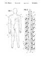
- FIG. 1is a diagrammatic plan view of a patient undergoing catheterization for heart blood vessel angioplasty and shows a catheter inserted percutaneously into and through the femoral artery to the heart, the proximal ends of the catheter and initial guidewire protruding proximally, and shows an extension guidewire;
- FIG. 2is an enlarged longitudinal sectional view of the catheter and guidewire with portions broken away;
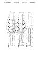
- FIG. 3is a plan view of a coiled plastic tube assembly mounting an extension guidewire constructed according to the teachings of the present invention
- FIG. 4is a fragmentary plan view of a portion of the coiled tube assembly shown in FIG. 1 and shows a small diameter tube fixed to the distal end of the extension guidewire inserted into a tool situated in an alignment tool holder mounted to the coiled tube assembly and a proximal end of the initial guidewire inserted into the tool for being guided into the small diameter tube;
- FIG. 5is an enlarged longitudinal sectional view of the tool showing the small diameter tubing inserted in the tool and the proximal end of the guidewire positioned for insertion into the tool;
- FIG. 6is an enlarged, longitudinal sectional view of the tool showing the small diameter tubing inserted in the tool, similar to the view shown in FIG. 5, and shows the proximal end of the guidewire inserted into a small coiled spring situated within the small diameter tube and fixed to the distal end of the guidewire extension guideline;
- FIG. 7is an enlarged longitudinal sectional view of the small diameter tube with the proximal end of the initial guidewire received therein and within the coiled spring;
- FIG. 8is an enlarged, longitudinal sectional view of the tube with the small tubing received therein and with the proximal end of the initial guidewire being pulled and simultaneously rotated in a direction which causes expansion of the coiled spring to allow the proximal end of the initial guidewire to be withdrawn from the small diameter tube.
- FIG. 1there is illustrated therein a patient 10 undergoing catheterization for heart angioplasty.
- a guiding catheter 12had been previously inserted percutaneously into and through the femoral artery into the heart 16.
- a balloon catheter 18(FIG. 2) with an initial guidewire 20 therein is inserted through the guiding catheter 12 to place a distal end portion 22 of the balloon catheter 18 (FIG. 2) and guidewire 20 within the heart.
- FIG. 2An enlarged view of a distal end portion 24 of the guiding catheter 12 having the distal end portion 22 of the balloon catheter 18 with a balloon formation 26, and a distal end 28 of the guidewire 20 therein is shown in FIG. 2. Also shown are the proximal ends 31, 32, 33 of the guiding catheter 12, the balloon catheter 18 and the guidewire 20, respectively. It will be understood that the proximal end 32 of the balloon catheter 18 is connected in a conventional manner to a source of dilatation fluid.
- the balloon catheter 18includes a main catheter portion 34 which is received over the initial guidewire, and a balloon catheter portion 36 which is received around and fixed to the main catheter portion 34 adjacent a distal end 38 of the main catheter portion 34.
- the balloon catheter portion 34includes the balloon formation 26 in the distal end portion of the balloon catheter 18 as shown.
- the distal end portion 22 of the balloon catheter 18 and initial guidewire 20are moved into an area of stenosis within a blood vessel. Then, a dilatation fluid is supplied through a annular space 38 between the balloon catheter portion 36 and the main catheter portion 34 to the balloon formation 26 for inflating or dilating same thereby to press the stenotic build-up outwardly against the walls of the blood vessel thereby to open the restricted passageway through the stenotic area.
- the balloon catheter 18 initial guidewire 20 and guiding catheter 12can be withdrawn or a stent can be implanted in the area of stenosis and then the balloon catheter 18, initial guidewire 20 and guiding catheter 12 are withdrawn.
- the balloon catheter 18 chosenis the wrong size, the balloon 26 being too small or to large. When this occurs, it is necessary to remove the balloon catheter 18 and replace the same with a new balloon catheter.
- the length of the initial guidewire 20is such that the whole assembly of balloon catheter 18 and guidewire 20 would have to be removed and replaced with a new balloon catheter and guidewire. This would be a tedious, painstaking and time consuming task, as well as unsafe, and it would be easier if the initial guidewire 20 could be left in place with the initial balloon catheter 18 being removed and then replaced with a new balloon catheter.
- techniqueshave been developed for using an exchange guidewire or an extendable guidewire which is capable of being attached and detached from the proximal end of the initially inserted guidewire 20.
- connection or attachment of an extension guidewirebe simple and be easily detachable while maintaining a firm attachment or connection between the extension guidewire and the initially inserted guidewire 20.
- FIGS. 3-8An extension guidewire 40 and connecting assembly 42 for connecting to the proximal end 33 of the inserted guidewire 20, constructed according to the teachings of the present invention for achieving this function is shown in FIGS. 3-8.
- the extension guidewire 40must have a sufficient length L so that the inserted balloon catheter 18 can be withdrawn over the initially inserted guidewire 20 and the extension guidewire 40 connected thereto and completely out of the guiding catheter 12 and then removed from the extension guidewire 40 so that a new balloon catheter then can be inserted over the extension guidewire 40 and then into the guiding catheter 12 over the initially inserted guidewire 20 to position the balloon 26 thereof in the area of stenosis to be treated.
- a coiled plastic tube assembly 44including a coiled plastic tube 46 which is held in a coiled position by four (4) holders 51-54 of the assembly.
- the holders 51-54have slots or holes 56 (FIG. 5) therethrough for receiving portions of the coiled tube 46.
- Two of the holders 51, 52have two slots/holes 56 and two holders 53, 54 have three slots/holes 56.
- One of the holders 53holds end portions 58, 60 of the coiled tube 46 with a distal end portion 62 of the extension guidewire 40 extending from the open upper or outer end 58 of the coiled tube 46 to and into one of the slots 56 in the holder 54 mounted on the coiled tube 46 a short distance from the holder 53.
- a distal end 64 of the extension guidewire 40is mounted in a small diameter tube 66, i.e. a tube having the diameter of a hypodermic needle, as shown in FIG. 5.
- the tube 66forms part of the connecting assembly 42 mounted to the distal end 64 of the extension guidewire 40.
- the tube 66is received in an alignment tool 70 mounted in one of the slots 56 in the holder 54.
- the alignment tool 70is cylindrical in structure and has a cylindrical throughbore 72 which flares or tapers outwardly at each end 74, 76 to facilitate insertion of the small diameter tube 66 in one end 74 and the proximal end 33 of the initial guidewire 20 at the other end 76.
- an open pitch, flat wire coiled spring 80inside the small diameter tube 66 of the connecting assembly 42 is an open pitch, flat wire coiled spring 80.
- the coiled spring 80has an internal diameter of approximately 0.008 inch and has an inner end 82 which is placed over the ground down distal end 64 of the extension guidewire 40 and welded thereto.
- the initial guidewire 20typically has an outer diameter of approximately 0.013-0.014 inch and the proximal end 33 of the initial guidewire 20 is ground down to approximately 0.009 inch.
- the tube 66has a detent or dimple 84 punched therein adjacent an outer end 85 of the tube 66 which engages and prevents an outer end 86 of the spring 80 from being moved out of the tube 66 when the spring 80 is urged out of the tube 66 when the initial guidewire 20 is pulled while the connecting assembly 42 is held against movement.
- the proximal end 33 of the initial guidewire 20is inserted into the tool 70 and the proximal end 33 is urged toward the connecting assembly 42 until the proximal end 33 of the initial guidewire 20 engages or bottoms against the distal end 64 of the extension guidewire 40 within the coiled flat wire spring 80. Coils of the flat wire spring 80 then grip or lock against the proximal end 33 of the initial guidewire 40.
- the above described assemblyestablishes a secure joint between the distal end 64 of the extension guidewire 40 and the proximal end 33 of the initial guidewire 20.
- the coiled tube 46can then be moved away from this joint to effect removal of the extension guidewire 40 from the coiled tube 46.
- the implanted "old" balloon catheter 18can be removed over the extension guidewire 40 and a new balloon catheter can be inserted over the extension guidewire 40 and the initial guidewire 20 to place a new balloon in the stenotic area in a blood vessel.
- the extension guidewire 40 and initial guidewire 20 assemblyis very effective since, as the proximal end 33 of the initial guidewire 20 is inserted into the coils of the flat wire coiled spring 80, the coils of the coiled spring 80 are forced to uncoil slightly, i.e., move in a direction which establishes a slightly greater inner diameter of the coils, so that the coils can receive therein the outer diameter of the proximal end 33 of the initial guidewire 20. Then, an axial force pulling the proximal end 33 away from the coiled spring 80 causes the coils around the proximal end 33 to tend to move toward a smaller inner diameter and that tendency establishes a locking connection between the coils and the proximal end 33.
- the extension guidewire 40If the extension guidewire 40 is pulled, the coiled spring 80 tries to axially extend causing it to try to reduce its internal diameter and this greatly increases the locking force of the flat wire coiled spring 80 against the proximal end 33 of the initial guidewire 20.
- the extension guidewire 40is a flexible 304 stainless steel wire coated with polymerized silicone.
- the extension guidewire 40is 125 cm. long and has a diameter of approximately 0.013-0.014 inch.
- the tube 66is made of 304 stainless steel and the spring 80 is made of a high tensile strength 304 stainless steel.
- the tube 66is colored a different color than the extension guidewire 40 to facilitate locating of the tube 66 by a medical practitioner.
- the connecting assembly 42including the tube 66 and the spring 80 can be reversed. That is to say, the connecting assembly 42 can be mounted on the proximal end 30 of the initial guidewire 20, and inserted in the alignment tool 70 to connect with the distal end 64 of the extension guidewire 40.
- the coiled tube assembly 44 with extension guidewire 40 thereinis packaged in a sterile pouch (not shown) and when used, the following steps are followed:
- CAUTIONBefore use, flush all devices entering the vascular system with sterile, heparinized saline or similar isotonic solution.
- the extension guidewire 40now can be disengaged from the primary or initial guidewire 20 if desired. This is achieved by holding the proximal end 33 of the primary or initial guidewire 20 while rotating the extension guidewire 40 in a direction so as to expand the spring to thereby loosen the spring, and at the same time gently pulling it backwards until it separates from the primary or initial guidewire 20.
- the extendable guidewire system including the extendable guidewire 40 and connecting assembly 42 of the present inventionhas a number of advantages some of which have been described above and others of which are inherent in the system. Additionally, modifications can be made to the extension guidewire system without departing from the teachings of the present invention. Accordingly, the scope of the invention is only to be limited as necessitated by the accompanying claims.
Landscapes
- Health & Medical Sciences (AREA)
- Life Sciences & Earth Sciences (AREA)
- Biophysics (AREA)
- Pulmonology (AREA)
- Engineering & Computer Science (AREA)
- Anesthesiology (AREA)
- Biomedical Technology (AREA)
- Heart & Thoracic Surgery (AREA)
- Hematology (AREA)
- Animal Behavior & Ethology (AREA)
- General Health & Medical Sciences (AREA)
- Public Health (AREA)
- Veterinary Medicine (AREA)
- Media Introduction/Drainage Providing Device (AREA)
Abstract
Description
Claims (15)
Priority Applications (4)
| Application Number | Priority Date | Filing Date | Title |
|---|---|---|---|
| US07/510,523US5113872A (en) | 1990-04-18 | 1990-04-18 | Guidewire extension system with connectors |
| US07/616,619US5117838A (en) | 1990-04-18 | 1990-11-21 | Rotating guidewire extension system |
| US07/860,264US5191888A (en) | 1990-04-18 | 1992-03-31 | Assembly of an extension guidewire and an alignment tool for same |
| US08/807,997US5813405A (en) | 1990-04-18 | 1997-03-03 | Snap-in connection assembly for extension guidewire system |
Applications Claiming Priority (1)
| Application Number | Priority Date | Filing Date | Title |
|---|---|---|---|
| US07/510,523US5113872A (en) | 1990-04-18 | 1990-04-18 | Guidewire extension system with connectors |
Related Child Applications (2)
| Application Number | Title | Priority Date | Filing Date |
|---|---|---|---|
| US07/616,619Continuation-In-PartUS5117838A (en) | 1990-04-18 | 1990-11-21 | Rotating guidewire extension system |
| US07/860,264Continuation-In-PartUS5191888A (en) | 1990-04-18 | 1992-03-31 | Assembly of an extension guidewire and an alignment tool for same |
Publications (1)
| Publication Number | Publication Date |
|---|---|
| US5113872Atrue US5113872A (en) | 1992-05-19 |
Family
ID=24031111
Family Applications (1)
| Application Number | Title | Priority Date | Filing Date |
|---|---|---|---|
| US07/510,523Expired - LifetimeUS5113872A (en) | 1990-04-18 | 1990-04-18 | Guidewire extension system with connectors |
Country Status (1)
| Country | Link |
|---|---|
| US (1) | US5113872A (en) |
Cited By (84)
| Publication number | Priority date | Publication date | Assignee | Title |
|---|---|---|---|---|
| WO1993003664A3 (en)* | 1991-08-21 | 1993-04-15 | Baxter Int | Guidewire extension system |
| US5246009A (en)* | 1991-09-20 | 1993-09-21 | Scimed Life Systems, Inc. | Guide wire assembly and method for catheter exchange |
| US5247942A (en)* | 1992-04-06 | 1993-09-28 | Scimed Life Systems, Inc. | Guide wire with swivel |
| US5269757A (en)* | 1991-12-02 | 1993-12-14 | C. R. Bard, Inc. | Catheter with integral steerable guidewire having linear to rotary movement |
| US5271415A (en)* | 1992-01-28 | 1993-12-21 | Baxter International Inc. | Guidewire extension system |
| US5282479A (en)* | 1992-10-13 | 1994-02-01 | Boc Health Care, Inc. | Guidewire introducer with guidewire grasp and release means |
| US5295492A (en)* | 1992-10-09 | 1994-03-22 | C. R. Bard, Inc. | Device for connecting a guidewire to an extension guidewire |
| US5365944A (en)* | 1992-10-09 | 1994-11-22 | C. R. Bard, Inc. | Guidewire extension with self-latching detachable connector |
| US5404886A (en)* | 1993-05-14 | 1995-04-11 | Schneider (Usa) Inc. | Exchangeable guidewire |
| US5415178A (en)* | 1991-08-26 | 1995-05-16 | Target Therapeutics | Extendable guidewire assembly |
| US5421722A (en)* | 1992-06-12 | 1995-06-06 | Stemmann; Hartmut | Magnet arrangement for a prosthesis |
| US5421348A (en)* | 1993-11-29 | 1995-06-06 | Cordis Corporation | Rotating guidewire extension system with mechanically locking extension wire |
| US5441055A (en)* | 1994-06-27 | 1995-08-15 | Cordis Corporation | Guidewire extension wire and connector assembly |
| US5464023A (en)* | 1994-01-31 | 1995-11-07 | Cordis Corporation | Magnetic exchange device for catheters |
| EP0689850A1 (en)* | 1994-05-11 | 1996-01-03 | Schneider (Europe) Ag | Docking assembly for the extension of a guidewire |
| US5505714A (en)* | 1992-01-13 | 1996-04-09 | Arrow International Investment Corp. | Non-rotational catheter compression clamp |
| US5513650A (en)* | 1995-02-28 | 1996-05-07 | Medtronic, Inc. | Guidewire extension connector - keyed joint |
| US5606980A (en)* | 1994-01-31 | 1997-03-04 | Cordis Corporation | Magnetic device for use with medical catheters and method |
| US5617875A (en)* | 1994-04-11 | 1997-04-08 | Schneider (Europe) A.G. | Interlocking guidewire connector |
| US5701911A (en)* | 1996-04-05 | 1997-12-30 | Medtronic, Inc. | Guide wire extension docking system |
| US5788653A (en)* | 1996-04-03 | 1998-08-04 | Cordis Corporation | Guidewire extension with sliding release mechanism |
| US5792075A (en)* | 1995-04-11 | 1998-08-11 | Schneider (Europe) A.G. | Method and apparatus for extending the length of a guide wire |
| US5813405A (en)* | 1990-04-18 | 1998-09-29 | Cordis Corporation | Snap-in connection assembly for extension guidewire system |
| US5813996A (en)* | 1995-12-21 | 1998-09-29 | Scimed Life Systems, Inc. | Guide wire extension system with magnetic coupling |
| US5820571A (en)* | 1996-06-24 | 1998-10-13 | C. R. Bard, Inc. | Medical backloading wire |
| US5827241A (en)* | 1995-06-07 | 1998-10-27 | C. R. Bard, Inc. | Rapid exchange guidewire mechanism |
| US6039700A (en)* | 1996-06-25 | 2000-03-21 | Schneider (Europe) A.G. | Docking assembly for the extension of a guidewire |
| US6080117A (en)* | 1997-10-16 | 2000-06-27 | Scimed Life Systems, Inc. | Guide wire extension system |
| US6193706B1 (en) | 1994-03-31 | 2001-02-27 | Lake Region Manufacturing Co., Inc. | Guidewire extension system with tactile connection indication |
| US20020133092A1 (en)* | 2001-03-16 | 2002-09-19 | Microvena Corporation | Wire convertible from over-the-wire length to rapid exchange length |
| US6491646B1 (en) | 1993-03-11 | 2002-12-10 | Lake Region Manufacturing, Inc. | Guidewire extension system |
| US20030040710A1 (en)* | 2001-08-24 | 2003-02-27 | Polidoro John M. | Blunting device for a hollow medical needle |
| WO2002030271A3 (en)* | 2000-10-12 | 2003-05-15 | Medtronic Percusurge Inc | Methods and apparatus for protecting the proximal end of a medical device |
| EP1344502A2 (en) | 2002-03-15 | 2003-09-17 | Medtronic Ave, Inc. | Temporary distal embolic protection device |
| WO2003084435A1 (en)* | 2002-04-04 | 2003-10-16 | Medtronic Ave, Inc. | Guide wire apparatus for prevention of distal atheroembolization |
| US6685653B2 (en) | 2001-12-19 | 2004-02-03 | Scimed Life Systems, Inc. | Extension system for pressure-sensing guidewires |
| US20040048230A1 (en)* | 1996-09-04 | 2004-03-11 | Ht Medical Systems, Inc. | Interface device and method for interfacing instruments to medical procedure simulation systems |
| US20040076940A1 (en)* | 1998-01-28 | 2004-04-22 | Immersion Medical, Inc. | Interface device and method for interfacing instruments to medical procedure simulation systems |
| WO2004089455A3 (en)* | 2003-04-03 | 2004-12-02 | Ethicon Endo Surgery Inc | Guide wire having bending segment |
| US6911016B2 (en) | 2001-08-06 | 2005-06-28 | Scimed Life Systems, Inc. | Guidewire extension system |
| US20050148902A1 (en)* | 2002-12-04 | 2005-07-07 | Lake Region Manufacturing, Inc. | Marked guidewires |
| US20050223327A1 (en)* | 2004-03-18 | 2005-10-06 | Cunningham Richard L | Medical device and procedure simulation |
| US20050256504A1 (en)* | 2004-05-14 | 2005-11-17 | Ethicon Endo-Surgery, Inc. | Medical instrument having a catheter and a medical guidewire |
| US20060079949A1 (en)* | 2004-10-12 | 2006-04-13 | Medtronic, Inc. | Lead stabilizer and extension wire |
| US20080045863A1 (en)* | 2006-08-17 | 2008-02-21 | Ethicon Endo-Surgery, Inc. | Guidewire structure including a medical guidewire |
| US20080058679A1 (en)* | 2006-08-17 | 2008-03-06 | Ethicon Endo-Surgery, Inc. | Guidewire structure including a medical guidewire and method for using a medical instrument |
| US20080064920A1 (en)* | 2006-09-08 | 2008-03-13 | Ethicon Endo-Surgery, Inc. | Medical drive system for providing motion to at least a portion of a medical apparatus |
| US20080097331A1 (en)* | 2006-09-05 | 2008-04-24 | Ethicon Endo-Surgery, Inc. | Guidewire structure including a medical guidewire and method for using |
| US7460104B2 (en) | 1995-01-18 | 2008-12-02 | Immersion Corporation | Laparoscopic simulation interface |
| US7527620B2 (en) | 2004-05-14 | 2009-05-05 | Ethicon Endo-Surgery, Inc. | Medical instrument having a medical guidewire |
| US20100100103A1 (en)* | 2008-09-15 | 2010-04-22 | Elcam Agricultural Cooperative Association Ltd. | Torque device with side attachment |
| US20110172604A1 (en)* | 2008-09-12 | 2011-07-14 | C. R. Bard, Inc. | Hybrid guidewire |
| US8425537B2 (en)* | 2006-07-31 | 2013-04-23 | Codman & Shurtleff, Inc. | Method of using interventional medical device system having an elongation retarding portion |
| US8900060B2 (en) | 2009-04-29 | 2014-12-02 | Ecp Entwicklungsgesellschaft Mbh | Shaft arrangement having a shaft which extends within a fluid-filled casing |
| US8926492B2 (en) | 2011-10-11 | 2015-01-06 | Ecp Entwicklungsgesellschaft Mbh | Housing for a functional element |
| US8932141B2 (en) | 2009-10-23 | 2015-01-13 | Ecp Entwicklungsgesellschaft Mbh | Flexible shaft arrangement |
| US8944748B2 (en) | 2009-05-05 | 2015-02-03 | Ecp Entwicklungsgesellschaft Mbh | Fluid pump changeable in diameter, in particular for medical application |
| US8979493B2 (en) | 2009-03-18 | 2015-03-17 | ECP Entwicklungsgesellscaft mbH | Fluid pump |
| US8998792B2 (en) | 2008-12-05 | 2015-04-07 | Ecp Entwicklungsgesellschaft Mbh | Fluid pump with a rotor |
| US9028216B2 (en) | 2009-09-22 | 2015-05-12 | Ecp Entwicklungsgesellschaft Mbh | Rotor for an axial flow pump for conveying a fluid |
| US9067006B2 (en) | 2009-06-25 | 2015-06-30 | Ecp Entwicklungsgesellschaft Mbh | Compressible and expandable blade for a fluid pump |
| US9089670B2 (en) | 2009-02-04 | 2015-07-28 | Ecp Entwicklungsgesellschaft Mbh | Catheter device having a catheter and an actuation device |
| US9089634B2 (en) | 2009-09-22 | 2015-07-28 | Ecp Entwicklungsgesellschaft Mbh | Fluid pump having at least one impeller blade and a support device |
| US9217442B2 (en) | 2010-03-05 | 2015-12-22 | Ecp Entwicklungsgesellschaft Mbh | Pump or rotary cutter for operation in a fluid |
| US9314558B2 (en) | 2009-12-23 | 2016-04-19 | Ecp Entwicklungsgesellschaft Mbh | Conveying blades for a compressible rotor |
| US9328741B2 (en) | 2010-05-17 | 2016-05-03 | Ecp Entwicklungsgesellschaft Mbh | Pump arrangement |
| US9339596B2 (en) | 2009-12-23 | 2016-05-17 | Ecp Entwicklungsgesellschaft Mbh | Radially compressible and expandable rotor for a fluid pump |
| US9358330B2 (en) | 2009-12-23 | 2016-06-07 | Ecp Entwicklungsgesellschaft Mbh | Pump device having a detection device |
| US9416783B2 (en) | 2009-09-22 | 2016-08-16 | Ecp Entwicklungsgellschaft Mbh | Compressible rotor for a fluid pump |
| US9416791B2 (en) | 2010-01-25 | 2016-08-16 | Ecp Entwicklungsgesellschaft Mbh | Fluid pump having a radially compressible rotor |
| US9603983B2 (en) | 2009-10-23 | 2017-03-28 | Ecp Entwicklungsgesellschaft Mbh | Catheter pump arrangement and flexible shaft arrangement having a core |
| US20170087335A1 (en)* | 2013-03-06 | 2017-03-30 | Cook Medical Technologies Llc | System for a wire-lumen free balloon catheter |
| US9611743B2 (en) | 2010-07-15 | 2017-04-04 | Ecp Entwicklungsgesellschaft Mbh | Radially compressible and expandable rotor for a pump having an impeller blade |
| US9771801B2 (en) | 2010-07-15 | 2017-09-26 | Ecp Entwicklungsgesellschaft Mbh | Rotor for a pump, produced with a first elastic material |
| US9867916B2 (en) | 2010-08-27 | 2018-01-16 | Berlin Heart Gmbh | Implantable blood conveying device, manipulating device and coupling device |
| US9895475B2 (en) | 2010-07-15 | 2018-02-20 | Ecp Entwicklungsgesellschaft Mbh | Blood pump for the invasive application within a body of a patient |
| US9968762B2 (en) | 2012-08-08 | 2018-05-15 | Cook Medical Technologies Llc | Wire guide with multiple tips |
| US9974893B2 (en) | 2010-06-25 | 2018-05-22 | Ecp Entwicklungsgesellschaft Mbh | System for introducing a pump |
| US10107299B2 (en) | 2009-09-22 | 2018-10-23 | Ecp Entwicklungsgesellschaft Mbh | Functional element, in particular fluid pump, having a housing and a conveying element |
| US10172985B2 (en) | 2009-08-06 | 2019-01-08 | Ecp Entwicklungsgesellschaft Mbh | Catheter device having a coupling device for a drive device |
| US10391278B2 (en) | 2011-03-10 | 2019-08-27 | Ecp Entwicklungsgesellschaft Mbh | Push device for the axial insertion of an elongate, flexible body |
| US10561773B2 (en) | 2011-09-05 | 2020-02-18 | Ecp Entwicklungsgesellschaft Mbh | Medical product comprising a functional element for the invasive use in a patient's body |
| US11471652B2 (en) | 2018-01-31 | 2022-10-18 | Lake Region Manufacturing, Inc. | Apparatus, system, and method for extending a guidewire |
| WO2023099961A1 (en) | 2021-12-01 | 2023-06-08 | Petrus Antonius Besselink | Extension system for coupling tubular devices |
Citations (8)
| Publication number | Priority date | Publication date | Assignee | Title |
|---|---|---|---|---|
| US161508A (en)* | 1875-03-30 | Improvement in belt-couplings | ||
| US839260A (en)* | 1905-09-01 | 1906-12-25 | Andrew Benson | Flexible connection. |
| US2077309A (en)* | 1937-04-13 | Belt fastener for round belts | ||
| US4846193A (en)* | 1987-09-21 | 1989-07-11 | Advanced Cardiovascular Systems, Inc. | Extendable guide wire for vascular procedures |
| US4875489A (en)* | 1987-08-14 | 1989-10-24 | Advanced Cardiovascular Systems, Inc. | Extendable guidewire |
| US4917094A (en)* | 1987-10-28 | 1990-04-17 | Medical Parameters Inc. | Guidewire advancement system |
| US4922923A (en)* | 1985-09-18 | 1990-05-08 | C. R. Bard, Inc. | Method for effecting a catheter exchange |
| US4961433A (en)* | 1988-11-02 | 1990-10-09 | Cardiometrics, Inc. | Guide wire assembly with electrical functions and male and female connectors for use therewith |
- 1990
- 1990-04-18USUS07/510,523patent/US5113872A/ennot_activeExpired - Lifetime
Patent Citations (8)
| Publication number | Priority date | Publication date | Assignee | Title |
|---|---|---|---|---|
| US161508A (en)* | 1875-03-30 | Improvement in belt-couplings | ||
| US2077309A (en)* | 1937-04-13 | Belt fastener for round belts | ||
| US839260A (en)* | 1905-09-01 | 1906-12-25 | Andrew Benson | Flexible connection. |
| US4922923A (en)* | 1985-09-18 | 1990-05-08 | C. R. Bard, Inc. | Method for effecting a catheter exchange |
| US4875489A (en)* | 1987-08-14 | 1989-10-24 | Advanced Cardiovascular Systems, Inc. | Extendable guidewire |
| US4846193A (en)* | 1987-09-21 | 1989-07-11 | Advanced Cardiovascular Systems, Inc. | Extendable guide wire for vascular procedures |
| US4917094A (en)* | 1987-10-28 | 1990-04-17 | Medical Parameters Inc. | Guidewire advancement system |
| US4961433A (en)* | 1988-11-02 | 1990-10-09 | Cardiometrics, Inc. | Guide wire assembly with electrical functions and male and female connectors for use therewith |
Cited By (179)
| Publication number | Priority date | Publication date | Assignee | Title |
|---|---|---|---|---|
| US5813405A (en)* | 1990-04-18 | 1998-09-29 | Cordis Corporation | Snap-in connection assembly for extension guidewire system |
| US5282478A (en)* | 1991-08-21 | 1994-02-01 | Baxter International, Inc. | Guidewire extension system with coil connectors |
| WO1993003664A3 (en)* | 1991-08-21 | 1993-04-15 | Baxter Int | Guidewire extension system |
| US5415178A (en)* | 1991-08-26 | 1995-05-16 | Target Therapeutics | Extendable guidewire assembly |
| US5246009A (en)* | 1991-09-20 | 1993-09-21 | Scimed Life Systems, Inc. | Guide wire assembly and method for catheter exchange |
| US5269757A (en)* | 1991-12-02 | 1993-12-14 | C. R. Bard, Inc. | Catheter with integral steerable guidewire having linear to rotary movement |
| US5505714A (en)* | 1992-01-13 | 1996-04-09 | Arrow International Investment Corp. | Non-rotational catheter compression clamp |
| US5271415A (en)* | 1992-01-28 | 1993-12-21 | Baxter International Inc. | Guidewire extension system |
| US5247942A (en)* | 1992-04-06 | 1993-09-28 | Scimed Life Systems, Inc. | Guide wire with swivel |
| US5421722A (en)* | 1992-06-12 | 1995-06-06 | Stemmann; Hartmut | Magnet arrangement for a prosthesis |
| US5365944A (en)* | 1992-10-09 | 1994-11-22 | C. R. Bard, Inc. | Guidewire extension with self-latching detachable connector |
| US5361777A (en)* | 1992-10-09 | 1994-11-08 | C.R. Bard, Inc. | Device for connecting a guidewire to an extension guidewire |
| US5295492A (en)* | 1992-10-09 | 1994-03-22 | C. R. Bard, Inc. | Device for connecting a guidewire to an extension guidewire |
| US5282479A (en)* | 1992-10-13 | 1994-02-01 | Boc Health Care, Inc. | Guidewire introducer with guidewire grasp and release means |
| US6491646B1 (en) | 1993-03-11 | 2002-12-10 | Lake Region Manufacturing, Inc. | Guidewire extension system |
| US5404886A (en)* | 1993-05-14 | 1995-04-11 | Schneider (Usa) Inc. | Exchangeable guidewire |
| US5511559A (en)* | 1993-05-14 | 1996-04-30 | Schneider (Usa) Inc. | Exchangeable guidewire |
| US5421348A (en)* | 1993-11-29 | 1995-06-06 | Cordis Corporation | Rotating guidewire extension system with mechanically locking extension wire |
| US5606980A (en)* | 1994-01-31 | 1997-03-04 | Cordis Corporation | Magnetic device for use with medical catheters and method |
| US5464023A (en)* | 1994-01-31 | 1995-11-07 | Cordis Corporation | Magnetic exchange device for catheters |
| US6193706B1 (en) | 1994-03-31 | 2001-02-27 | Lake Region Manufacturing Co., Inc. | Guidewire extension system with tactile connection indication |
| US5617875A (en)* | 1994-04-11 | 1997-04-08 | Schneider (Europe) A.G. | Interlocking guidewire connector |
| US5605163A (en)* | 1994-05-11 | 1997-02-25 | Schneider (Europe) A.G. | Guidewire attachment assembly |
| EP0689850A1 (en)* | 1994-05-11 | 1996-01-03 | Schneider (Europe) Ag | Docking assembly for the extension of a guidewire |
| AU685595B2 (en)* | 1994-05-11 | 1998-01-22 | Schneider (Europe) Ag | Docking assembly for the extension of a guidewire |
| US5782776A (en)* | 1994-05-11 | 1998-07-21 | Schneider A.G. | Guidewire attachment assembly |
| US5441055A (en)* | 1994-06-27 | 1995-08-15 | Cordis Corporation | Guidewire extension wire and connector assembly |
| US7460104B2 (en) | 1995-01-18 | 2008-12-02 | Immersion Corporation | Laparoscopic simulation interface |
| US5513650A (en)* | 1995-02-28 | 1996-05-07 | Medtronic, Inc. | Guidewire extension connector - keyed joint |
| US5792075A (en)* | 1995-04-11 | 1998-08-11 | Schneider (Europe) A.G. | Method and apparatus for extending the length of a guide wire |
| US5827241A (en)* | 1995-06-07 | 1998-10-27 | C. R. Bard, Inc. | Rapid exchange guidewire mechanism |
| US5813996A (en)* | 1995-12-21 | 1998-09-29 | Scimed Life Systems, Inc. | Guide wire extension system with magnetic coupling |
| US5788653A (en)* | 1996-04-03 | 1998-08-04 | Cordis Corporation | Guidewire extension with sliding release mechanism |
| US5701911A (en)* | 1996-04-05 | 1997-12-30 | Medtronic, Inc. | Guide wire extension docking system |
| US5820571A (en)* | 1996-06-24 | 1998-10-13 | C. R. Bard, Inc. | Medical backloading wire |
| US6039700A (en)* | 1996-06-25 | 2000-03-21 | Schneider (Europe) A.G. | Docking assembly for the extension of a guidewire |
| US7931470B2 (en) | 1996-09-04 | 2011-04-26 | Immersion Medical, Inc. | Interface device and method for interfacing instruments to medical procedure simulation systems |
| US8480406B2 (en) | 1996-09-04 | 2013-07-09 | Immersion Medical, Inc. | Interface device and method for interfacing instruments to medical procedure simulation systems |
| US20040048230A1 (en)* | 1996-09-04 | 2004-03-11 | Ht Medical Systems, Inc. | Interface device and method for interfacing instruments to medical procedure simulation systems |
| US20040045561A1 (en)* | 1996-09-04 | 2004-03-11 | Immersion Medical, Inc. | Interface device and method for interfacing instruments to medical procedure simulation systems |
| US7833018B2 (en) | 1996-09-04 | 2010-11-16 | Immersion Corporation | Interface device and method for interfacing instruments to medical procedure simulation systems |
| US6328702B1 (en) | 1997-10-16 | 2001-12-11 | Scimed Life Systems, Inc. | Guide wire extension system |
| US6080117A (en)* | 1997-10-16 | 2000-06-27 | Scimed Life Systems, Inc. | Guide wire extension system |
| US7806696B2 (en)* | 1998-01-28 | 2010-10-05 | Immersion Corporation | Interface device and method for interfacing instruments to medical procedure simulation systems |
| US20040076940A1 (en)* | 1998-01-28 | 2004-04-22 | Immersion Medical, Inc. | Interface device and method for interfacing instruments to medical procedure simulation systems |
| WO2002030271A3 (en)* | 2000-10-12 | 2003-05-15 | Medtronic Percusurge Inc | Methods and apparatus for protecting the proximal end of a medical device |
| US8298160B2 (en)* | 2001-03-16 | 2012-10-30 | Ev3 Inc. | Wire convertible from over-the-wire length to rapid exchange length |
| US20020133092A1 (en)* | 2001-03-16 | 2002-09-19 | Microvena Corporation | Wire convertible from over-the-wire length to rapid exchange length |
| US6911016B2 (en) | 2001-08-06 | 2005-06-28 | Scimed Life Systems, Inc. | Guidewire extension system |
| US7001361B2 (en)* | 2001-08-24 | 2006-02-21 | Medical Engenuity Llc | Blunting device for a hollow medical needle |
| US20030040710A1 (en)* | 2001-08-24 | 2003-02-27 | Polidoro John M. | Blunting device for a hollow medical needle |
| US6685653B2 (en) | 2001-12-19 | 2004-02-03 | Scimed Life Systems, Inc. | Extension system for pressure-sensing guidewires |
| EP1344502A2 (en) | 2002-03-15 | 2003-09-17 | Medtronic Ave, Inc. | Temporary distal embolic protection device |
| WO2003084435A1 (en)* | 2002-04-04 | 2003-10-16 | Medtronic Ave, Inc. | Guide wire apparatus for prevention of distal atheroembolization |
| US20050148902A1 (en)* | 2002-12-04 | 2005-07-07 | Lake Region Manufacturing, Inc. | Marked guidewires |
| WO2004089455A3 (en)* | 2003-04-03 | 2004-12-02 | Ethicon Endo Surgery Inc | Guide wire having bending segment |
| US20090181350A1 (en)* | 2004-03-18 | 2009-07-16 | Immersion Medical, Inc. | Medical Device And Procedure Simulation |
| US20050223327A1 (en)* | 2004-03-18 | 2005-10-06 | Cunningham Richard L | Medical device and procedure simulation |
| US9336691B2 (en) | 2004-03-18 | 2016-05-10 | Immersion Corporation | Medical device and procedure simulation |
| US7505030B2 (en) | 2004-03-18 | 2009-03-17 | Immersion Medical, Inc. | Medical device and procedure simulation |
| US20050256504A1 (en)* | 2004-05-14 | 2005-11-17 | Ethicon Endo-Surgery, Inc. | Medical instrument having a catheter and a medical guidewire |
| US8100882B2 (en) | 2004-05-14 | 2012-01-24 | Ethicon Endo-Surgery, Inc. | Guidewire structure |
| US7527620B2 (en) | 2004-05-14 | 2009-05-05 | Ethicon Endo-Surgery, Inc. | Medical instrument having a medical guidewire |
| US7758564B2 (en) | 2004-05-14 | 2010-07-20 | Ethicon Endo-Surgery, Inc. | Medical instrument having a catheter and a medical guidewire |
| US7785269B2 (en) | 2004-05-14 | 2010-08-31 | Ethicon Endo-Surgery, Inc. | Medical instrument having a guidewire and an add-to catheter |
| US7828791B2 (en) | 2004-05-14 | 2010-11-09 | Ethicon Endo-Surgery, Inc. | Medical instrument having a guidewire and articulated catheter |
| US7896862B2 (en) | 2004-05-14 | 2011-03-01 | Ethicon Endo-Surgery, Inc. | Medical instrument having a controlled guidewire drive |
| US20060079949A1 (en)* | 2004-10-12 | 2006-04-13 | Medtronic, Inc. | Lead stabilizer and extension wire |
| US7283878B2 (en) | 2004-10-12 | 2007-10-16 | Medtronic, Inc. | Lead stabilizer and extension wire |
| US8425537B2 (en)* | 2006-07-31 | 2013-04-23 | Codman & Shurtleff, Inc. | Method of using interventional medical device system having an elongation retarding portion |
| US8002714B2 (en) | 2006-08-17 | 2011-08-23 | Ethicon Endo-Surgery, Inc. | Guidewire structure including a medical guidewire and method for using a medical instrument |
| US20080045863A1 (en)* | 2006-08-17 | 2008-02-21 | Ethicon Endo-Surgery, Inc. | Guidewire structure including a medical guidewire |
| US20080058679A1 (en)* | 2006-08-17 | 2008-03-06 | Ethicon Endo-Surgery, Inc. | Guidewire structure including a medical guidewire and method for using a medical instrument |
| US20080097331A1 (en)* | 2006-09-05 | 2008-04-24 | Ethicon Endo-Surgery, Inc. | Guidewire structure including a medical guidewire and method for using |
| US20080064920A1 (en)* | 2006-09-08 | 2008-03-13 | Ethicon Endo-Surgery, Inc. | Medical drive system for providing motion to at least a portion of a medical apparatus |
| US20110172604A1 (en)* | 2008-09-12 | 2011-07-14 | C. R. Bard, Inc. | Hybrid guidewire |
| US20100100103A1 (en)* | 2008-09-15 | 2010-04-22 | Elcam Agricultural Cooperative Association Ltd. | Torque device with side attachment |
| US11852155B2 (en) | 2008-12-05 | 2023-12-26 | Ecp Entwicklungsgesellschaft Mbh | Fluid pump with a rotor |
| US9404505B2 (en) | 2008-12-05 | 2016-08-02 | Ecp Entwicklungsgesellschaft Mbh | Fluid pump with a rotor |
| US10662967B2 (en) | 2008-12-05 | 2020-05-26 | Ecp Entwicklungsgesellschaft Mbh | Fluid pump with a rotor |
| US12209593B2 (en) | 2008-12-05 | 2025-01-28 | Ecp Entwicklungsgesellschaft Mbh | Fluid pump with a rotor |
| US10495101B2 (en) | 2008-12-05 | 2019-12-03 | Ecp Entwicklungsgesellschaft Mbh | Fluid pump with a rotor |
| US8998792B2 (en) | 2008-12-05 | 2015-04-07 | Ecp Entwicklungsgesellschaft Mbh | Fluid pump with a rotor |
| US9964115B2 (en) | 2008-12-05 | 2018-05-08 | Ecp Entwicklungsgesellschaft Mbh | Fluid pump with a rotor |
| US10406323B2 (en) | 2009-02-04 | 2019-09-10 | Ecp Entwicklungsgesellschaft Mbh | Catheter device having a catheter and an actuation device |
| US12377246B2 (en) | 2009-02-04 | 2025-08-05 | Ecp Entwicklungsgesellschaft Mbh | Catheter device having a catheter and an actuation device |
| US9981110B2 (en) | 2009-02-04 | 2018-05-29 | Ecp Entwicklungsgesellschaft Mbh | Catheter device having a catheter and an actuation device |
| US9089670B2 (en) | 2009-02-04 | 2015-07-28 | Ecp Entwicklungsgesellschaft Mbh | Catheter device having a catheter and an actuation device |
| US11969560B2 (en) | 2009-02-04 | 2024-04-30 | Ecp Entwicklungsgesellschaft Mbh | Catheter device having a catheter and an actuation device |
| US9649475B2 (en) | 2009-02-04 | 2017-05-16 | Ecp Entwicklungsgesellschaft Mbh | Catheter device having a catheter and an actuation device |
| US11229774B2 (en) | 2009-02-04 | 2022-01-25 | Ecp Entwicklungsgesellschaft Mbh | Catheter device having a catheter and an actuation device |
| US8979493B2 (en) | 2009-03-18 | 2015-03-17 | ECP Entwicklungsgesellscaft mbH | Fluid pump |
| US8900060B2 (en) | 2009-04-29 | 2014-12-02 | Ecp Entwicklungsgesellschaft Mbh | Shaft arrangement having a shaft which extends within a fluid-filled casing |
| US9512839B2 (en) | 2009-05-05 | 2016-12-06 | Ecp Entwicklungsgesellschaft Mbh | Fluid pump changeable in diameter, in particular for medical application |
| US8944748B2 (en) | 2009-05-05 | 2015-02-03 | Ecp Entwicklungsgesellschaft Mbh | Fluid pump changeable in diameter, in particular for medical application |
| US11278711B2 (en) | 2009-05-05 | 2022-03-22 | Ecp Entwicklungsgesellschaft Mbh | Fluid pump changeable in diameter, in particular for medical application |
| US11577066B2 (en) | 2009-05-05 | 2023-02-14 | Ecp Entwicklundgesellschaft Mbh | Fluid pump changeable in diameter, in particular for medical application |
| US10265448B2 (en) | 2009-05-05 | 2019-04-23 | Ecp Entwicklungsgesellschaft Mbh | Fluid pump changeable in diameter, in particular for medical application |
| US11786718B2 (en) | 2009-05-05 | 2023-10-17 | Ecp Entwicklungsgesellschaft Mbh | Fluid pump changeable in diameter, in particular for medical application |
| US11268521B2 (en) | 2009-06-25 | 2022-03-08 | Ecp Entwicklungsgesellschaft Mbh | Compressible and expandable blade for a fluid pump |
| US10330101B2 (en) | 2009-06-25 | 2019-06-25 | Ecp Entwicklungsgesellschaft Mbh | Compressible and expandable blade for a fluid pump |
| US11994133B2 (en) | 2009-06-25 | 2024-05-28 | Ecp Entwicklungsgesellschaft Mbh | Compressible and expandable blade for a fluid pump |
| US9067006B2 (en) | 2009-06-25 | 2015-06-30 | Ecp Entwicklungsgesellschaft Mbh | Compressible and expandable blade for a fluid pump |
| US12372092B2 (en) | 2009-06-25 | 2025-07-29 | Ecp Entwicklungsgesellschaft Mbh | Compressible and expandable blade for a fluid pump |
| US12042647B2 (en) | 2009-08-06 | 2024-07-23 | Ecp Entwicklungsgesellschaft Mbh | Catheter device having a coupling device for a drive device |
| US11116960B2 (en) | 2009-08-06 | 2021-09-14 | Ecp Entwicklungsgesellschaft Mbh | Catheter device having a coupling device for a drive device |
| US10172985B2 (en) | 2009-08-06 | 2019-01-08 | Ecp Entwicklungsgesellschaft Mbh | Catheter device having a coupling device for a drive device |
| US12276285B2 (en) | 2009-09-22 | 2025-04-15 | Ecp Entwicklungsgesellschaft Mbh | Compressible rotor for a fluid pump |
| US12066030B2 (en) | 2009-09-22 | 2024-08-20 | Ecp Entwicklungsgesellschaft Mbh | Fluid pump having at least one impeller blade and a support device |
| US11592028B2 (en) | 2009-09-22 | 2023-02-28 | Ecp Entwicklungsgesellschaft Mbh | Fluid pump having at least one impeller blade and a support device |
| US11773861B2 (en) | 2009-09-22 | 2023-10-03 | Ecp Entwicklungsgesellschaft Mbh | Compressible rotor for a fluid pump |
| US10107299B2 (en) | 2009-09-22 | 2018-10-23 | Ecp Entwicklungsgesellschaft Mbh | Functional element, in particular fluid pump, having a housing and a conveying element |
| US9028216B2 (en) | 2009-09-22 | 2015-05-12 | Ecp Entwicklungsgesellschaft Mbh | Rotor for an axial flow pump for conveying a fluid |
| US10208763B2 (en) | 2009-09-22 | 2019-02-19 | Ecp Entwicklungsgesellschaft Mbh | Fluid pump having at least one impeller blade and a support device |
| US11421701B2 (en) | 2009-09-22 | 2022-08-23 | Ecp Entwicklungsgesellschaft Mbh | Compressible rotor for a fluid pump |
| US9416783B2 (en) | 2009-09-22 | 2016-08-16 | Ecp Entwicklungsgellschaft Mbh | Compressible rotor for a fluid pump |
| US9089634B2 (en) | 2009-09-22 | 2015-07-28 | Ecp Entwicklungsgesellschaft Mbh | Fluid pump having at least one impeller blade and a support device |
| US12313113B2 (en) | 2009-10-23 | 2025-05-27 | Ecp Entwicklungsgesellschaft Mbh | Catheter pump arrangement and flexible shaft arrangement having a core |
| US10792406B2 (en) | 2009-10-23 | 2020-10-06 | Ecp Entwicklungsgesellschaft Mbh | Catheter pump arrangement and flexible shaft arrangement having a core |
| US9603983B2 (en) | 2009-10-23 | 2017-03-28 | Ecp Entwicklungsgesellschaft Mbh | Catheter pump arrangement and flexible shaft arrangement having a core |
| US8932141B2 (en) | 2009-10-23 | 2015-01-13 | Ecp Entwicklungsgesellschaft Mbh | Flexible shaft arrangement |
| US9314558B2 (en) | 2009-12-23 | 2016-04-19 | Ecp Entwicklungsgesellschaft Mbh | Conveying blades for a compressible rotor |
| US11266824B2 (en) | 2009-12-23 | 2022-03-08 | Ecp Entwicklungsgesellschaft Mbh | Conveying blades for a compressible rotor |
| US11549517B2 (en) | 2009-12-23 | 2023-01-10 | Ecp Entwicklungsgesellschaft Mbh | Conveying blades for a compressible rotor |
| US10561772B2 (en) | 2009-12-23 | 2020-02-18 | Ecp Entwicklungsgesellschaft Mbh | Pump device having a detection device |
| US12305662B2 (en) | 2009-12-23 | 2025-05-20 | Ecp Entwicklungsgesellschaft Mbh | Conveying blades for a compressible rotor |
| US9339596B2 (en) | 2009-12-23 | 2016-05-17 | Ecp Entwicklungsgesellschaft Mbh | Radially compressible and expandable rotor for a fluid pump |
| US11486400B2 (en) | 2009-12-23 | 2022-11-01 | Ecp Entwicklungsgesellschaft Mbh | Pump device having a detection device |
| US9358330B2 (en) | 2009-12-23 | 2016-06-07 | Ecp Entwicklungsgesellschaft Mbh | Pump device having a detection device |
| US10806838B2 (en) | 2009-12-23 | 2020-10-20 | Ecp Entwicklungsgesellschaft Mbh | Conveying blades for a compressible rotor |
| US12158151B2 (en) | 2009-12-23 | 2024-12-03 | Ecp Entwicklungsgesellschaft Mbh | Pump device having a detection device |
| US12117014B2 (en) | 2009-12-23 | 2024-10-15 | Ecp Entwicklungsgesellschaft Mbh | Conveying blades for a compressible rotor |
| US12085088B2 (en) | 2009-12-23 | 2024-09-10 | Ecp Entwicklungsgesellschaft Mbh | Radially compressible and expandable rotor for a fluid pump |
| US11773863B2 (en) | 2009-12-23 | 2023-10-03 | Ecp Entwicklungsgesellschaft Mbh | Conveying blades for a compressible rotor |
| US11434922B2 (en) | 2009-12-23 | 2022-09-06 | Ecp Entwicklungsgesellschaft Mbh | Radially compressible and expandable rotor for a fluid pump |
| US11781557B2 (en) | 2009-12-23 | 2023-10-10 | Ecp Entwicklungsgesellschaft Mbh | Radially compressible and expandable rotor for a fluid pump |
| US9903384B2 (en) | 2009-12-23 | 2018-02-27 | Ecp Entwicklungsgesellschaft Mbh | Radially compressible and expandable rotor for a fluid pump |
| US10557475B2 (en) | 2009-12-23 | 2020-02-11 | Ecp Entwicklungsgesellschaft Mbh | Radially compressible and expandable rotor for a fluid pump |
| US11815097B2 (en) | 2009-12-23 | 2023-11-14 | Ecp Entwicklungsgesellschaft Mbh | Pump device having a detection device |
| US9795727B2 (en) | 2009-12-23 | 2017-10-24 | Ecp Entwicklungsgesellschaft Mbh | Pump device having a detection device |
| US10316853B2 (en) | 2010-01-25 | 2019-06-11 | Ecp Entwicklungsgesellschaft Mbh | Fluid pump having a radially compressible rotor |
| US12018698B2 (en) | 2010-01-25 | 2024-06-25 | Ecp Entwicklungsgesellschaft Mbh | Fluid pump having a radially compressible rotor |
| US9416791B2 (en) | 2010-01-25 | 2016-08-16 | Ecp Entwicklungsgesellschaft Mbh | Fluid pump having a radially compressible rotor |
| US11517739B2 (en) | 2010-01-25 | 2022-12-06 | Ecp Entwicklungsgesellschaft Mbh | Fluid pump having a radially compressible rotor |
| US11986205B2 (en) | 2010-03-05 | 2024-05-21 | Ecp Entwicklungsgesellschaft Mbh | Pump or rotary cutter for operation in a fluid |
| US9907891B2 (en) | 2010-03-05 | 2018-03-06 | Ecp Entwicklungsgesellschaft Mbh | Pump or rotary cutter for operation in a fluid |
| US10413646B2 (en) | 2010-03-05 | 2019-09-17 | Ecp Entwicklungsgesellschaft Mbh | Pump or rotary cutter for operation in a fluid |
| US9217442B2 (en) | 2010-03-05 | 2015-12-22 | Ecp Entwicklungsgesellschaft Mbh | Pump or rotary cutter for operation in a fluid |
| US11976674B2 (en) | 2010-05-17 | 2024-05-07 | Ecp Entwicklungsgesellschaft Mbh | Pump arrangement |
| US9759237B2 (en) | 2010-05-17 | 2017-09-12 | Ecp Entwicklungsgesellschaft Mbh | Pump arrangement |
| US9328741B2 (en) | 2010-05-17 | 2016-05-03 | Ecp Entwicklungsgesellschaft Mbh | Pump arrangement |
| US11168705B2 (en) | 2010-05-17 | 2021-11-09 | Ecp Entwicklungsgesellschaft Mbh | Pump arrangement |
| US10221866B2 (en) | 2010-05-17 | 2019-03-05 | Ecp Entwicklungsgesellschaft Mbh | Pump arrangement |
| US9974893B2 (en) | 2010-06-25 | 2018-05-22 | Ecp Entwicklungsgesellschaft Mbh | System for introducing a pump |
| US11957846B2 (en) | 2010-06-25 | 2024-04-16 | Ecp Entwicklungsgesellschaft Mbh | System for introducing a pump |
| US10898625B2 (en) | 2010-06-25 | 2021-01-26 | Ecp Entwicklungsgesellschaft Mbh | System for introducing a pump |
| US10874781B2 (en) | 2010-06-25 | 2020-12-29 | Ecp Entwicklungsgesellschaft Mbh | System for introducing a pump |
| US11913467B2 (en) | 2010-07-15 | 2024-02-27 | Ecp Entwicklungsgesellschaft Mbh | Radially compressible and expandable rotor for a pump having an impeller blade |
| US11844939B2 (en) | 2010-07-15 | 2023-12-19 | Ecp Entwicklungsgesellschaft Mbh | Blood pump for the invasive application within a body of a patient |
| US9771801B2 (en) | 2010-07-15 | 2017-09-26 | Ecp Entwicklungsgesellschaft Mbh | Rotor for a pump, produced with a first elastic material |
| US10920596B2 (en) | 2010-07-15 | 2021-02-16 | Ecp Entwicklungsgesellschaft Mbh | Radially compressible and expandable rotor for a pump having an impeller blade |
| US10589012B2 (en) | 2010-07-15 | 2020-03-17 | Ecp Entwicklungsgesellschaft Mbh | Blood pump for the invasive application within a body of a patient |
| US9895475B2 (en) | 2010-07-15 | 2018-02-20 | Ecp Entwicklungsgesellschaft Mbh | Blood pump for the invasive application within a body of a patient |
| US11702938B2 (en) | 2010-07-15 | 2023-07-18 | Ecp Entwicklungsgesellschaft Mbh | Rotor for a pump, produced with a first elastic material |
| US10584589B2 (en) | 2010-07-15 | 2020-03-10 | Ecp Entwicklungsgellschaft Mbh | Rotor for a pump having helical expandable blades |
| US9611743B2 (en) | 2010-07-15 | 2017-04-04 | Ecp Entwicklungsgesellschaft Mbh | Radially compressible and expandable rotor for a pump having an impeller blade |
| US12065941B2 (en) | 2010-07-15 | 2024-08-20 | Ecp Entwicklungsgesellschaft Mbh | Rotor for a pump, produced with a first elastic material |
| US11083885B2 (en) | 2010-08-27 | 2021-08-10 | Berlin Heart Gmbh | Implantable blood conveying device, manipulating device and coupling device |
| US9867916B2 (en) | 2010-08-27 | 2018-01-16 | Berlin Heart Gmbh | Implantable blood conveying device, manipulating device and coupling device |
| US10391278B2 (en) | 2011-03-10 | 2019-08-27 | Ecp Entwicklungsgesellschaft Mbh | Push device for the axial insertion of an elongate, flexible body |
| US11235125B2 (en) | 2011-03-10 | 2022-02-01 | Ecp Entwicklungsgesellschaft Mbh | Push device for the axial insertion of an elongate, flexible body |
| US11666746B2 (en) | 2011-09-05 | 2023-06-06 | Ecp Entwicklungsgesellschaft Mbh | Medical product comprising a functional element for the invasive use in a patient's body |
| US10561773B2 (en) | 2011-09-05 | 2020-02-18 | Ecp Entwicklungsgesellschaft Mbh | Medical product comprising a functional element for the invasive use in a patient's body |
| US8926492B2 (en) | 2011-10-11 | 2015-01-06 | Ecp Entwicklungsgesellschaft Mbh | Housing for a functional element |
| US10821269B2 (en) | 2012-08-08 | 2020-11-03 | Cook Medical Technologies Llc | Wire guide with multiple tips |
| US9968762B2 (en) | 2012-08-08 | 2018-05-15 | Cook Medical Technologies Llc | Wire guide with multiple tips |
| US20170087335A1 (en)* | 2013-03-06 | 2017-03-30 | Cook Medical Technologies Llc | System for a wire-lumen free balloon catheter |
| US11471652B2 (en) | 2018-01-31 | 2022-10-18 | Lake Region Manufacturing, Inc. | Apparatus, system, and method for extending a guidewire |
| WO2023099961A1 (en) | 2021-12-01 | 2023-06-08 | Petrus Antonius Besselink | Extension system for coupling tubular devices |
Similar Documents
| Publication | Publication Date | Title |
|---|---|---|
| US5113872A (en) | Guidewire extension system with connectors | |
| US5117838A (en) | Rotating guidewire extension system | |
| US5421348A (en) | Rotating guidewire extension system with mechanically locking extension wire | |
| US5139032A (en) | Fixed balloon on a guidewire extension wire system and kit | |
| JP2735690B2 (en) | Replaceable guidewire | |
| US5191888A (en) | Assembly of an extension guidewire and an alignment tool for same | |
| EP0347035B1 (en) | Guidewire extension with selflatching detachable connection | |
| US5607406A (en) | Rapid exchange segmented catheter | |
| US6911016B2 (en) | Guidewire extension system | |
| US5439445A (en) | Support catheter assembly | |
| US5788653A (en) | Guidewire extension with sliding release mechanism | |
| EP1599246B1 (en) | Medical device delivery system | |
| US4781682A (en) | Catheter having support flaps and method of inserting catheter | |
| EP1240915B1 (en) | Wire having a definied location of frangibility | |
| US20050267563A1 (en) | Exchangeable delivery system for expandable prosthetic devices | |
| US5195535A (en) | Detachable guidewire extension | |
| AU1910992A (en) | Diameter expansion cannula | |
| JPH0525512B2 (en) | ||
| EP0591945A1 (en) | Guidewire extension with selflatching detachable connector | |
| EP0747081A2 (en) | Rapid exchanger guidewire mechanism | |
| US20050205446A1 (en) | Packaging assembly for a catheter | |
| US5341817A (en) | Elongated guidewire for use in dilation procedures | |
| US6217526B1 (en) | Detachable guidewire extension | |
| EP0678307B1 (en) | Balloon catheter and stent delivery system | |
| US5460614A (en) | Guidewire trapping catheter |
Legal Events
| Date | Code | Title | Description |
|---|---|---|---|
| AS | Assignment | Owner name:CORDIS CORPORATION, A CORP. OF FL, FLORIDA Free format text:ASSIGNMENT OF ASSIGNORS INTEREST.;ASSIGNOR:VIERA, FERNANDO M.;REEL/FRAME:005355/0769 Effective date:19900329 Owner name:CORDIS CORPORATION, A CORP. OF FL, FLORIDA Free format text:ASSIGNMENT OF ASSIGNORS INTEREST.;ASSIGNOR:BOX, J. WILLIAM;REEL/FRAME:005355/0771 Effective date:19900417 Owner name:CORDIS CORPORATION, A CORP. OF FL, FLORIDA Free format text:ASSIGNMENT OF ASSIGNORS INTEREST.;ASSIGNOR:JAHRMARKT, SCOTT L.;REEL/FRAME:005355/0767 Effective date:19900329 | |
| CC | Certificate of correction | ||
| FEPP | Fee payment procedure | Free format text:PAYOR NUMBER ASSIGNED (ORIGINAL EVENT CODE: ASPN); ENTITY STATUS OF PATENT OWNER: LARGE ENTITY | |
| FPAY | Fee payment | Year of fee payment:4 | |
| FPAY | Fee payment | Year of fee payment:8 | |
| STCF | Information on status: patent grant | Free format text:PATENTED CASE | |
| DI | Adverse decision in interference | Effective date:20000314 | |
| DI | Adverse decision in interference | Effective date:20000314 | |
| FPAY | Fee payment | Year of fee payment:12 |