US5113249A - Method for preparing polychromatic printing plates - Google Patents
Method for preparing polychromatic printing platesDownload PDFInfo
- Publication number
- US5113249A US5113249AUS07/545,805US54580590AUS5113249AUS 5113249 AUS5113249 AUS 5113249AUS 54580590 AUS54580590 AUS 54580590AUS 5113249 AUS5113249 AUS 5113249A
- Authority
- US
- United States
- Prior art keywords
- color
- frame
- block
- special
- separations
- Prior art date
- Legal status (The legal status is an assumption and is not a legal conclusion. Google has not performed a legal analysis and makes no representation as to the accuracy of the status listed.)
- Expired - Lifetime
Links
- 238000000034methodMethods0.000titleclaimsabstractdescription48
- 238000007639printingMethods0.000titleclaimsabstractdescription37
- 238000000926separation methodMethods0.000claimsabstractdescription168
- 230000007547defectEffects0.000claimsabstractdescription12
- 230000008859changeEffects0.000claimsabstractdescription11
- 235000019557luminanceNutrition0.000abstractdescription26
- 239000003086colorantSubstances0.000description75
- 230000008569processEffects0.000description33
- 238000011282treatmentMethods0.000description29
- 239000000976inkSubstances0.000description21
- 238000009432framingMethods0.000description14
- PCHJSUWPFVWCPO-UHFFFAOYSA-NgoldChemical compound[Au]PCHJSUWPFVWCPO-UHFFFAOYSA-N0.000description5
- 229910052737goldInorganic materials0.000description5
- 239000010931goldSubstances0.000description5
- 229910052709silverInorganic materials0.000description5
- 239000004332silverSubstances0.000description5
- 238000010586diagramMethods0.000description3
- 238000004519manufacturing processMethods0.000description3
- 230000002452interceptive effectEffects0.000description2
- 230000007480spreadingEffects0.000description2
- 238000003892spreadingMethods0.000description2
- 241001609030Brosme brosmeSpecies0.000description1
- 241000023320Luma <angiosperm>Species0.000description1
- 238000004040coloringMethods0.000description1
- 238000003066decision treeMethods0.000description1
- 230000006870functionEffects0.000description1
- 238000007646gravure printingMethods0.000description1
- OSWPMRLSEDHDFF-UHFFFAOYSA-Nmethyl salicylateChemical compoundCOC(=O)C1=CC=CC=C1OOSWPMRLSEDHDFF-UHFFFAOYSA-N0.000description1
- 238000012986modificationMethods0.000description1
- 230000004048modificationEffects0.000description1
- 238000001228spectrumMethods0.000description1
Images


Classifications
- H—ELECTRICITY
- H04—ELECTRIC COMMUNICATION TECHNIQUE
- H04N—PICTORIAL COMMUNICATION, e.g. TELEVISION
- H04N1/00—Scanning, transmission or reproduction of documents or the like, e.g. facsimile transmission; Details thereof
- H04N1/46—Colour picture communication systems
- H04N1/56—Processing of colour picture signals
- H04N1/58—Edge or detail enhancement; Noise or error suppression, e.g. colour misregistration correction
Definitions
- the present inventionrelates to the field of preparing polychromatic printing plates, and particularly to a method for reducing or eliminating defects caused by misregistration of the polychromatic printing plates.
- an imageis reproduced by three or four printing inks which are printed on top of each other.
- the appropriate amounts of the three or four printing inks for printing cyan (C), magenta (M), and yellow (Y), and frequency black (K),are placed upon each image point, preferably in that order.
- the printing inkmay include other colors, such as gold, silver, green, etc., called "special" colors.
- the amounts of the printing inks which are determined by printing ink signalsare defined as color separation signals.
- CEPSColor Electronic Prepress Systems
- One method in use for generating the framesautomatically frames each color area according to the color separations that it contains.
- the luminance (i.e., darkness) of each color separationis determined, and the framing is effected, according to the color separation having the highest luminance, the other separations being shrunk with respect to the corresponding separations of the other color.
- Such a methodis not entirely satisfactory since it does not take into consideration the bordering colors of each color pair, or the percentages in each separation.
- An object of the present inventionis to provide an improved method and system for preparing polychromatic printing plates in order to reduce or eliminate defects caused by misregistration of the plates.
- a method of processing a file of recorded color separation values of color elements for use in preparing polychromatic printing plates in order to reduce or eliminate defects caused by misregistration by printingcomprising the steps: (a) defining a plurality of predetermined color types; (b) identifying the color pairs where there is a change in color between adjacent color element; and (c) for each color pair, determining whether or not to make a frame according to first predetermined criteria based on specific combination of color types in the pair, and then according to the second predetermined criteria based on the difference in luminance between corresponding color separations in the respective pair.
- the location of the frameis determined according to third predetermined criteria based on specific combinations of color types in the pair, and then according to fourth predetermined criteria based on the sum of the luminances of each color in the color pair.
- the frameis generated in the direction of the color having the higher sum of luminances. More particularly, this is done by spreading the darker separations of the lighter color in the direction of the darker color.
- a frameis not generated when the common luminances in the same separations between bordering process colors that are not black are above a predetermined value.
- one color of the pairis defined as being a white frame, the frame is generated towards the other color of the pair, and the color of the frame is zero coverage in the process colors;
- one color of the pairis a base color and also contains a process color, and the other is a non-base color, the frame is generated towards the base color, and the frame color is the original color without the base;
- one color of the pairis black and the other is a special, the frame is generated towards the darker color, and the color of the frame is the combination of black and special;
- the two colors of the pairare specials not to be printed with the same ink, the frame is generated towards the darker color, and the color of the frame is a combination of the two specials;
- one color of the pairis a special color
- the otheris a special plus a process color
- the darkest special separations of the two colorsare not to be printed with the same ink
- the frameis generated towards the color having the darkest special separation
- the frame coloris the darkest special separation plus the other separations of the second color
- one coloris a window, semi-tint or tint type, the other color is black, and at least one of the C,M,Y separations differs significantly in the two colors;
- the frameis generated towards the black; and the frame color is the black separation from the black color and the C,M,Y separations from the other color;
- one color of the pairis black and the other is a window, tint or semi-tint type, at least one of the C,M,Y separations differs significantly among the two colors, and one of the two bordering colors includes a special separation, the frame is generated towards the special; and the frame color is a combination of the special color and the process separations of the other color;
- one color of the pairis black and the other is of the window or semi-tint type, at least one of the C,M,Y separations differs significantly among the two colors, and there was an overlap transparent instruction, the frame is generated towards the semi-tint or window; and the frame color is the black separation from the black color, and the other separations from the other color;
- one color of the pairis of the window type and the other color is of the tint type, at least one of the tint C,M,Y separations is significantly darker from the other, and one color includes a special separation, the frame is generated towards the color including the special separation; and the frame color includes the special separation of the special color and other separations of the other colors;
- one color of the pairis of the window type, and the other is of the tint type, at least one of the tint C,M,Y separations is significantly darker than the other, and there was an overlap transparent instruction, the frame is generated towards the window type color; and the frame color is the darkest separation of both colors;
- one color of the pairis of the window type, and the other is of the tint type, at least one of the tint C,M,Y separations is significantly darker than the other, and the difference between the darkness of the color areas of the two colors is less than a defined parameter, one half of the frame is generated towards one color and the other half of the frame is generated towards the other color; and the frame color is the darkest separation of both colors;
- one color of the pairis of the window type and the other is of the tint type, and at least one of the tint C,M,Y separations is significantly darker than the other, but the difference between the darkness of the color areas of the two colors is more than a defined parameter, the frame is generated towards the tint type; and the frame color is the darkest separation of both colors;
- one coloris of the window type and the other is tint considered as a yellow color area, and the tint includes a special, the frame is generated towards the special; and the frame color is the special separation from the special color and the other separations from the other color;
- one color of the pairis of the window type and the other is tint considered as a yellow color area, but the tint does not include a special, the frame is generated towards the tint; and the frame color is the CMK separations from the yellow color area and the yellow separation from the other color, plus the difference of percent between two yellow separations multiplied by a predetermined user-defined factor;
- both colors of the pairare of the semi-tint type and one includes a special separation, the frame is generated towards the color having the special separation; and the frame color is the special separations from the special color, and the other separations from the other color;
- one color of the pairis of the yellow area type and the other is of the semi-tint or tint type that includes a special separation, the frame is generated towards the color of the special separation; and the frame color is the special separations from the special color, and the other separations from the other color;
- one coloris of the semi-tint type considered as a yellow area type, and the other is of the tint type, the frame is generated towards the semi-tint type; and the frame color is the C,M,K separations from the yellow area, and the Y separation from the other color, plus the difference of percent between two yellow separations multiplied by a predetermined user-defined factor;
- both colors of the pairare either of the tint or semi-tint type, at least two separations differ significantly in opposite directions, and one color includes a special separation, the frame is generated towards the color including the special separation; and the frame color is the special separations from the special color, and the other separations from the other color;
- one color of the pairis of the semi-tint type, and the other is of the tint type, at least two separations differ significantly in opposite directions, and an overlap transparent instruction was made, the frame is generated towards the semi-tint; and the frame color is the highest percentage in each separation, corresponding darker separations from the lighter area being reduced by the differences in percentage in the same separation between the lighter and darker areas multiplied by a factor;
- one color of the pairis of the tint or semi-tint type and the other is tint, at least two separations differ significantly in opposite directions, the common luminance is less than a predefined parameter, and the difference between the darkness of the color areas of the two colors is less than a defined parameter, one half the frame is generated towards one color, and the other one half frame is generated towards the other color; and the frame color is the highest percentage in each separation, corresponding darker separations from the lighter area being reduced by the difference in percentage in the corresponding separation between the lighter and darker area multiplied by a factor;
- one color of the pairis of the tint or semi-tint type, the other is tint, at least two separations differ significantly in opposite directions, the common luminance is less than a predefined parameter, and the difference between the darkness of the colors areas is more than a defined parameter, the frame is generated towards the darker color; and the frame color is the highest percentage in each separation, corresponding darker separations from the lighter area being reduced by the difference in percentage in the corresponding separation between the lighter and darker areas multiplied by a factor;
- one color of the pairincludes a special separation, and the other is of the tint or semi-tint type, and the process color is darker than the color including the special separation, the frame is generated towards the process color; and the frame color is the special separations from the special color, and other separations from the other color;
- one color of the pairincludes a special separation and the other is of the tint or semi-tint type, but the process color is not darker than the special color, the frame is generated in the direction of the special color; and the frame color is the special separations from the special color, and the other separations from the other color;
- one color of the pairis of the window type, and the other is of the special type, and it was not instructed to overlap transparent, the frame is generated towards the special type; and the frame color is the special separations from the special color, and other separations from the other color.
- the method of the present inventionthus systematically performs a series of checks on each color pair in order to determine whether or not to create a frame. As soon as a color pair matches a specific situation, a frame is generated of a frame color and direction according to the values of the color pair. The direction of the frame is towards the darker color area, i.e., towards the color with the higher luminance, called the reference or boundary color; and the frame color is always at least as dark, and usually darker, than the reference color from which it is created.
- the inventionprovides a fully automatic framing system which obviates the need for the expertise and experience of the operator heretofore required to reduce defects caused by misregistration of the polychromatic printing plates.
- the systemalso relieves the operator of the considerable time heretofore required to perform such framing operations.
- the inventionalso provides apparatus for processing a file of recorded separation values of color elements for use in making polychromatic printing plates in order to reduce or eliminate defects caused by misregistration of the plates.
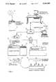
- FIG. 1pictorially illustrates an overall EPC process for preparing polychromatic printing plates in accordance with the present invention
- FIG. 2is a block diagram illustrating the automatic framing system in the overall process of FIG. 1;
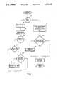
- FIG. 3is a flow chart illustrating the overall process of framing in the system of FIG. 2;
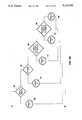
- FIG. 4A and 4B connected a shown in FIG. 4are a flow chart illustrating the frame decision method in the flow chart of FIG. 3;
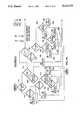
- FIGS. 5, 6, 7A and 7B connected a shown in FIG. 7, 8, 9are flow charts illustrating Treatments 1-5, respectively, in the flow chart of FIG. 4;
- FIG. 10illustrates several examples of border areas of different colors and involving the generation of frames
- FIG. 11illustrates the frames generated in the bordering areas illustrated in FIG. 10.
- FIG. 1illustrates an example of the overall EPC process for preparing polychromatic printing plates.
- the input to the processmay be or include "originals” (i.e., transparencies), or "mechanicals” (i.e., black and white sheets illustrating the layout).
- the inputted datais scanned (block 3) for each original or mechanical and recorded in a disk 4.
- Other datasuch as from a magnetic tape, may also be inputted or may have been pre-recorded, in disk 4, as schematically shown at 5.
- All the originals and mechanicalsare then assembled into one layout at an interactive work station 6. This is done by feeding the data recorded on disk 4, as well operator-inputted data from a work station 7, via a central processor unit (CPU) 8, to the interactive work station 6. After the full layout is assembled, it is fed through the CPU 8 to an automatic framing system (AFS) 9, where the framing process, to be described below, is executed in order to reduce or eliminate defects caused by misregistration of the ultimately produced polychromatic printing plates.
- AFSautomatic framing system
- the datais then recorded in a laser plotter 10 or a gravure printing machine 11, depending on the type of printing to be used. If a laser plotter is used, film separations are produced, as shown at 12, and then printed out as shown at 13; whereas if a gravure machine 11 is used, the information is utilized to engrave the cylinder, as shown at 14, and then printed out.
- FIG. 2is a block diagram illustrating the automatic framing system represented by block 9 in FIG. 1 in which frames are generated, where required, between color pairs in order to reduce or eliminate defects caused by misregistration of the polychromatic printing plates when printing the final copy.
- Disk 4has recorded thereon two files of color separation values.
- One fileincludes the color separation values of the flat areas or line work, namely those color elements of the same value for certain running lengths as recorded in the files this file serves as the overall mask and is sometimes referred to as the "mask file”.
- the second filereferred to as the “continuous tone file” has recorded thereon the color separation values of color elements which change from one element to the next.
- the mask fileis normally used for preparing the polychromatic printing plates, except where a color area is designated “transparent”; in such case the color separation values of the mask file are ignored, and the color separation values in the continuous tone file are used.
- each line of datamay include about 3,000 color elements in each horizontal line, and there may be about 2,000 horizontal lines in a page.
- the systemreads each line, counts the color elements in the respective line, and identifies the color of each element by a number, all of which are recorded in memory 15 together with the line number.
- Each color elementis compared with five bordering coloring elements (i.e., the three bordering elements in the previous line and the two adjacent ones in the same line) to determine whether there is a color change.
- the systemthus identifies the color pairs where there is a change in color between adjacent color elements. For each color pair, it determines, according to predetermined criteria, whether or not a frame is to be generated for the respective color pair. For those color pairs in which a frame is to be generated, the system determines, according to other predetermined criteria, the location and color separation values of the frame with respect to the two colors of the pair. Such locations and color separation values are recorded in a frame buffer 16. The recorded locations and color separation values of the frames are subsequently used, with the recorded separation values of the color elements, for preparing the polychromatic printing plates according to the overall process illustrated in FIG. 1.
- the automatic printing system illustrated in FIG. 2further includes a video unit 17 and a monitor unit 18 enabling the operator to monitor the results and to modify the results if necessary by inputting data via the work station input 7.
- FIG. 3more particularly illustrates the software-control process of the automatic framing system represented by block 9 in FIG. 1 and shown in the hardware block diagram of FIG. 2.
- circle 20designates a loop in which the lines are read one after the other.
- the color pairsare found (block 22) by identifying those where there is a change in color between adjacent color elements. Since the color pairs are found not only between color elements of the same line, but also between adjacent lines, the memory always retains three lines to enable pairs between lines to be compared.
- the predetermined valueis determined according to the four color separations for each color.
- Every color pairis recorded in the memory only once, and every subsequence recurrence of that particular pair is ignored at this stage.
- a loopis executed (circle 23) to determine whether that particular pair had been previously identified (block 24). If yes, nothing further occurs; but if not, a decision is made (block 25) whether that particular color pair is to be framed; and if so, it is entered in the frame list (block 26) stored in the frame buffer 16 (FIG. 2).
- Decision block 25makes the following decisions with respect to each color pair:
- the list prepared (block 26) as a result of the frame decisions in block 25includes only the frames to be generated; where a color pair is not to generate a frame, it is not entered in this list.
- the systemthen proceeds to perform the frame functions according to the list (block 27). That is, the previously-prepared files of the four color separations is modified according to the prepared list of the color pairs for generating frames.
- the so-prepared fileis thus a combination of the scanned information and the frames to be generated.
- the filemay also include other data inputted by the operator, e.g., special graphic shapes, background shading, etc., as well as text inputted from a front- end system, e.g., word processor, etc.
- the operatoralso predefines the number of separations required for a particular job. For example, the specification may specify that a particular area will be of a special color, such as gold or silver, which cannot be produced by the normal four color separations. This would require the creation of a new color separation that will be printed with a specific ink to show the special color (e.g., gold or silver).
- a special colorsuch as gold or silver
- FIGS. 4-9are flow charts illustrating the process for making the frame decisions represented by decision block 25 in FIG. 3. However, these decisions are based on pre-programmed data as appearing in the following Tables 1, 2 and 3.
- Table 1identifies various area types and their order of precedence (hierarchy) in the frame decisions made in the flow charts of FIGS. 4-9. Thus, if the decision tree illustrated in the flow charts of FIGS. 4-9 determines that a particular color pair is in an area type of high priority, it makes its decision based on that area type, without checking further. Some of the area types are inputted by the operator, and others are inputted by the computer.
- the area type of highest priorityis that designated NBC (No Base color). This area type is inputted by the operator with respect to all the areas including the background base color (e.g., white).
- An area defined as NBCmay include any percentage and any type of color separations, including special colors.
- the next order of priority of area types on Table 1includes S (special), MS (multi-special) and SP (special plus process). These area types are also operator inputted and identify those areas where special color inks will be printed. Area S will be printed with a special ink; area MS will be printed with more than one special ink; and area SP will be printed with a special ink on top of the process (CMYK) inks.
- Sspecial
- MSmulti-special
- SPspecial plus process
- the area type of next priorityis designated in Table 1 is K (black), namely an area in which the percent of black (K) separation is above a predetermined minimum percentage (e.g., 85%), regardless of the percentage of the other three color separations.
- Area K typeis computer inputted.
- Wwindow
- Ttint
- BGbackground
- STsini-tint
- An areais designated as W (window) when it has a continuous tone (CT) in all separations, as T (tint) when it has flat areas in all separations, as BG (background) when nothing is printed, and as ST (semi-tint) when some separations are flat and others are CT.
- CTcontinuous tone
- Table 2is a list of conditions, each identified by a symbol, used in the frame decision flow charts, particularly in the flow charts of FIGS. 5-10 describing the various Treatments referred in the overall frame decision flow chart of FIG. 4. These conditions set forth in Table 2 are referred to in the Treatment flow charts of FIGS. 5-10, as described below.
- Table 3lists, by numbers 1-11, a set of instructions to be followed for determining the color separation values of the generated frame. These instructions appear in the frame decision flow chart of FIG. 4 and in the Treatment flow charts of FIGS. 5-10, and will also be referred to below in the description of the flow charts of FIGS. 4-10.
- the systemfirst reads the color pair A,B (block 40) previously identified, and the area type (block 41) obtained from Table 1 discussed above, and then decides whether one color is a white frame (block 42). If yes, a decision is made to generate a frame in the direction of the non-white color (block 43).
- the systemchecks to determine whether to frame only when a "special application" is involved, e.g., only special colors (block 44). If so, a check is made as to whether both colors are of the area type NBC (Background Base) of Table 1 (block 45), and if so, no frame is generated. If both colors of the color pair are not of the type NBC, a check is made whether the two colors are NBC and another color process or special process or special color. If so, a frame is generated in the direction of the second color (block 47); but if not, the system executes Treatment 5 (block 48), described below with respect to FIG. 10.
- NBCBackground Base
- Treatment 5block 48
- a frameis required not only when a "special application" is involved (block 44), a check is made whether the two colors are of the NVC (Table 1) type (block 49); and if so, no frame is generated. However, if they are not both of this type, a check is made (block 50) whether one of the two colors is of the NBC type and the other is a special process color; and if so, a frame is generated (block 51) in the direction of the special or process color.
- NVCTable 1
- the color pairdoes not include a color of the area type NBC and a special or process color (block 50)
- the systemchecks to determine whether the two colors of the pair are of the type W and T, as defined in Table 1 (block 54); and if so, the system executes Treatment 2 (block 55), described below with respect to FIG. 6.
- the systemchecks to determine whether the two colors of the pair are of the area types represented by any of the combinations specified in block 56; and if so, the system executes Treatment 3 illustrated in the flow chart of FIG. 7 (block 57).
- the systemchecks to determine whether the color pair is any of the combinations illustrated in block 58 of FIG. 4, and if so, the system executes Treatment 4 (block 59) illustrated by the flow chart of FIG. 8; and if not, it executes Treatment 5 (block 60) illustrated by the flow chart of FIG. 9.
- the flow chart of FIG. 5describes Treatment 1 as represented by block 53 in the frame decision flow chart of FIG. 4. As described there, this treatment is effected when one of the colors of the color pair is black (K), and the other is one of the area types W,T or ST, all as defined in Table 1. Treatment 1 is also effected when one of the two colors includes a special color.
- Treatment 1a check is first made (block 70) as to whether it was predefined not to frame windows. If so, a check is made whether the other color is a W (window) (block 71). If so, no frame is generated.
- This condition(first item in Table 2) is that at least one of the CMY separations differs significantly of one color element from the other color element according to a predetermined threshold, as preset by the operator. If this condition is found to be present, a check is made (block 73) whether one of the colors is a special color; and if so, a frame is generated according to instruction 3 of Table 3 in the direction of the special color (block 74). If one of the two colors checked by block 73 is not a special color, then a frame is generated according to instruction 3 of Table 3 in the direction of the black (block 75).
- a checkis made (block 76), similar to the check made in block 72, namely whether at least one of the CMY separations of one color element differs significantly from that of the other color element. If so, a check is then made (block 77) whether one color is a special color; and if so, a frame is generated in the direction of the special color according to Instruction 3 in Table 3 (block 78).
- FIG. 6is a flow chart of Treatment 2 which, as shown by block 55 in FIG. 4, is executed when the two colors of the pair are of the area types W (windown) and T (tint), as more particularly defined in Table 1.
- the systemfirst checks whether the operator has inputted an instruction not to frame the window (block 90); if such an instruction has been inputted, no frame is generated.
- the systemchecks for the condition "COM L" (block 91), namely whether the sum of the common luminance in the same separations between the bordering colors is high (i.e., above a predetermined threshold, as operator inputted). If so, no frame is generated.
- FIG. 7illustrates the flow chart for executing Treatment 3 (namely block 57 in FIG. 4), when the two colors of the pair are both in are types T or ST. Treatment 3 is also followed when one color may be a special color.
- the systemfirst checks to determine whether both colors A, B are in area types ST (semi-tint, Table 1), as indicated by block 110. If so, a check is made to determine whether one of the colors is a special color (block 111), and if so, a frame is generated in the direction of the special color according to Instruction 6 of Table 3. If one of the colors is not a special color, no frame is generated.
- a checkis made as to the presence of the condition set forth in block 113, namely whether the sum of the common luminance in the same separations between the bordering colors is above a predetermined threshold (Table 2). If yes, a check is made (block 114) whether one of the colors is yellow (according to Table 2); and if so, a check is then made to determine whether one of the colors is a special color (block 115). If one of the colors is indeed a special color, a frame is generated in the direction of the special color (block 116) according to Instruction 6 of Table 3.
- FIG. 8is a flow chart illustrating Treatment 4, namely block 59 in FIG. 4, wherein one of the colors is a special, and the other color is of the area type W,T or ST (as defined in Table 1).
- FIG. 9is a flow chart of Treatment 5 represented by blocks 48 and 60 in the frame decision flow chart of FIG. 4. This treatment is executed whenever the two colors A,B of the color pair are any of the combinations listed at the top of FIG. 9.
- a checkis first made (block 150) whether the two colors are black (K) and a special color (S). If so, a check is made whether the condition specified in block 151 is present, namely whether the luminance of the special color is greater than the sum of the luminance of the color separations CMYK that have 100% (Table 2). If the decision in block 151 is positive, a frame is generated in the direction of the special color according to Instruction 3 of Table 3 (block 152), and if the decision is negative, a frame is generated in the direction of K (black) according to Instruction 8 of Table 3.
- FIG. 10illustrates eight examples of bordering color elements 1-8 having color separation values according to Table 4 as set forth below. Besides the four process color separations CMYK, two special colors, such as gold and silver, are identified in the fifth and sixth separation layers. The values set forth describe the ink coverage percentages.
- FIG. 11illustrates the frames generated between the various color pairs according to the above-described flow charts.
- the color separation values of the generated framesare set forth in Table 5 below.
- Table 5also sets forth the decision blocks in the above-described flow charts which determine the location and color separation values of the generated frames.
Landscapes
- Engineering & Computer Science (AREA)
- Multimedia (AREA)
- Signal Processing (AREA)
- Facsimile Image Signal Circuits (AREA)
- Manufacture Or Reproduction Of Printing Formes (AREA)
- Color Image Communication Systems (AREA)
- Laminated Bodies (AREA)
- Printing Methods (AREA)
- Image Processing (AREA)
- Manufacturing Of Printed Wiring (AREA)
Abstract
Description
TABLE I __________________________________________________________________________PRIOR- SEPARATIONS ITY AREA TYPES C M Y B S1 S2 REMARKS __________________________________________________________________________1 BGB = Background Any percentage and type Color area considered Base as BG because it is defined as No Base Color. 2 S = Special * The area will be printed withspecial ink 2 MS = Multi * * The area will be Special printed with more than onespecial ink 2 SP = Special + % % CT % * The area will be Process printed with a special ink on top of theprocess inks 3 =Black Any percentage % Percents in black are and types above a minimum defined 4 W = Window CT CT CT CT CT in all separations 4 T = Tint % % % %Flat area 4 BG = Background -- -- -- -- Nothing is printed 4 ST = Semi-Tint % CT % CT Some separations are flat and others CT. __________________________________________________________________________ Other Terms: L = Luminance This is the amount of darkness/brightness of a separation and/or a color area.
TABLE II ______________________________________ Explanation to the Questions in the Charts ______________________________________Diff 1 At least one of the C, M, Y separations has to differ significantly.Diff 2 At least one of the Tint C, M, Y separations has to be darker significantly.Diff 3 At least two separations to differ significantly in opposite directions. Dark The sum of luminance of all separations in the Dark color is higher than the sum of Lumin- ance of all separations of the other color. LUMS = Opaque The luminance of the special color is greater than the sum of luminance of C, M, Y, K that have 100 percents. Yellow If a color area had the following characteris- tics it is considered as "Yellow": 1. A very high percentage in the yellow separation. 2. The sum of luminance in the C, M, B sep- arations is high. 3. The bordering color area is not a "Yellow". 4. There is at least one significantly diferent among the C, M, B separations of the bor- dering colors. Com L The sum of common Luminance in the same separations between the bordering colors is high. Same Group The system checks whether a two bordering special separations are going to be printed with the same ink. Overlap Trans A decision whether to always overlap color areas that contain a CT in one of their separa- tions. ΔL < Params The difference between the darkness of color- areas A, B is less than a defined parameter. LumA > LumB the overall darkness of color A is greater than the overall darkness of color B. Dark of A, B The darkest separations of A and B are print- Same Group ed with the same ink. ______________________________________
TABLE III ______________________________________ FRAME COLOR INSTRUCTION TABLE ______________________________________ 1. Zero percents in all C, M, Y, B and special separations except in the special white if it exists. 2. All C, M, Y, B and special remain the same, the special White becomes zero percent. 3. Black separation percents from the Black Color. C, M, Y percentage from the other color. 4. Half the size of the frame to each direction. Highest percentage in each separation. A special, if exist doesn't change. 5. Highest percentage in each separation. Adjacent separations from the lighter area are reduced by the difference of percentage between the lighter and darker area multiplied by a predetermined user-defined factor. 6. Special separations from "Special" color. Other separations from theother color 7. C, M, B separations from the "Yellow" area, Y Separation from the other color, plus the difference of percent between two yellow separations multiplied by a predetermined user- defined factor. 8. C, M, Y, B from "Black" color area. Special separations from "Special color". 9. Special separations from " Special areas A and B". 10. The darkest special separation of the dark color area and the other special separations of the other color area. 11. All separations as the overlapped color plus the special of the other color area. ______________________________________
TABLE 4 ______________________________________ C M Y K 5th 6th ______________________________________ 1 = 0 50 100 0 -- -- 2 = 40 0 0 0 -- -- 3 = 60 0 0 100 -- -- 4 = 100 100 0 0 -- -- 5 = ct ct ct ct -- -- 6 = -- -- -- -- 100 -- 7 = -- -- -- -- -- 100 8 = -- -- -- -- 100 100 ______________________________________
TABLE 5 ______________________________________ Per Decision C M Y K 5th 6th Box ______________________________________ #9 = 25 50 100 0 -- -- 132 #10 = 100 100 70 0 -- -- 131 #11 = 100 100 ct ct -- -- 99 #12 = 100 100 0 0 100 -- 145 #13 = ctct ct ct 100 -- 144 #14 = ctct ct ct 100 100 144 #15 = ct ct ct ct -- 100 144 #16 = 60 0 0 100 -- 100 145 #17 = 40 0 ct 0 -- 100 144 #18 = 40 0ct 100 -- 100 81 ______________________________________
Claims (2)
Priority Applications (3)
| Application Number | Priority Date | Filing Date | Title |
|---|---|---|---|
| US07/843,338US5323248A (en) | 1990-03-02 | 1992-02-28 | Method and apparatus for preparing polychromatic printing plates |
| US08/215,546US5420702A (en) | 1990-03-02 | 1994-03-22 | Method for preparing polychromatic printing plates |
| US08/435,431US5481379A (en) | 1990-03-02 | 1995-05-10 | Method for preparing polychromatic printing plates |
Applications Claiming Priority (2)
| Application Number | Priority Date | Filing Date | Title |
|---|---|---|---|
| IL93607AIL93607A (en) | 1990-03-02 | 1990-03-02 | Method and system for preparing polychromatic printing plates |
| IL93607 | 1990-03-02 |
Related Child Applications (1)
| Application Number | Title | Priority Date | Filing Date |
|---|---|---|---|
| US07/843,338ContinuationUS5323248A (en) | 1990-03-02 | 1992-02-28 | Method and apparatus for preparing polychromatic printing plates |
Publications (1)
| Publication Number | Publication Date |
|---|---|
| US5113249Atrue US5113249A (en) | 1992-05-12 |
Family
ID=11060976
Family Applications (4)
| Application Number | Title | Priority Date | Filing Date |
|---|---|---|---|
| US07/545,805Expired - LifetimeUS5113249A (en) | 1990-03-02 | 1990-06-29 | Method for preparing polychromatic printing plates |
| US07/843,338Expired - LifetimeUS5323248A (en) | 1990-03-02 | 1992-02-28 | Method and apparatus for preparing polychromatic printing plates |
| US08/215,546Expired - LifetimeUS5420702A (en) | 1990-03-02 | 1994-03-22 | Method for preparing polychromatic printing plates |
| US08/435,431Expired - LifetimeUS5481379A (en) | 1990-03-02 | 1995-05-10 | Method for preparing polychromatic printing plates |
Family Applications After (3)
| Application Number | Title | Priority Date | Filing Date |
|---|---|---|---|
| US07/843,338Expired - LifetimeUS5323248A (en) | 1990-03-02 | 1992-02-28 | Method and apparatus for preparing polychromatic printing plates |
| US08/215,546Expired - LifetimeUS5420702A (en) | 1990-03-02 | 1994-03-22 | Method for preparing polychromatic printing plates |
| US08/435,431Expired - LifetimeUS5481379A (en) | 1990-03-02 | 1995-05-10 | Method for preparing polychromatic printing plates |
Country Status (7)
| Country | Link |
|---|---|
| US (4) | US5113249A (en) |
| EP (1) | EP0445066B1 (en) |
| JP (1) | JPH04216988A (en) |
| AT (1) | ATE129111T1 (en) |
| CA (1) | CA2036751C (en) |
| DE (2) | DE445066T1 (en) |
| IL (1) | IL93607A (en) |
Cited By (44)
| Publication number | Priority date | Publication date | Assignee | Title |
|---|---|---|---|---|
| US5257097A (en)* | 1991-09-27 | 1993-10-26 | Eastman Kodak Company | Method and apparatus for selective interception of a graphics rendering operation for effecting image data modification |
| US5272549A (en)* | 1991-11-01 | 1993-12-21 | Mcdonald Bruce A | Apparatus for electronic editing of integrated color images with related text material and employing an image frame |
| US5295236A (en)* | 1991-03-04 | 1994-03-15 | Aldus Corporation | Applying traps to a printed page specified in a page description language format |
| US5321799A (en)* | 1992-04-17 | 1994-06-14 | Proxim, Inc. | Signalling transition control in a modulated-signal communications system |
| US5323248A (en)* | 1990-03-02 | 1994-06-21 | Scitex Corporation Ltd. | Method and apparatus for preparing polychromatic printing plates |
| US5333068A (en)* | 1988-09-20 | 1994-07-26 | Canon Kabushiki Kaisha | Image processing system |
| US5440652A (en)* | 1993-09-10 | 1995-08-08 | Athena Design Systems, Inc. | Method and apparatus for preparing color separations based on n-way color relationships |
| US5542052A (en)* | 1991-03-04 | 1996-07-30 | Adobe Systems Incorporated | Applying traps to a printed page specified in a page description language format |
| US5583647A (en)* | 1993-05-05 | 1996-12-10 | Ohio Electronic Engravers, Inc. | Cylinder support apparatus and method for use in an engraver |
| US5666543A (en)* | 1994-03-23 | 1997-09-09 | Adobe Systems Incorporated | Method of trapping graphical objects in a desktop publishing program |
| US5668931A (en)* | 1993-03-31 | 1997-09-16 | Dermer; Richard A. | Method for automatic trap selection for correcting for plate misregistration in color printing |
| US5752057A (en)* | 1994-10-27 | 1998-05-12 | Shira Computers Ltd. | Method for conversion of a color electronic pre-press system data file to a page description language data file |
| US5864651A (en)* | 1995-06-25 | 1999-01-26 | Scitex Corporation Ltd. | System and method for on-demand printing |
| US6055064A (en)* | 1994-10-27 | 2000-04-25 | Shira Computers Ltd. | Method for conversion of a color electronic pre-press system data file to a page description language data file |
| DE19912511A1 (en)* | 1999-03-19 | 2000-09-21 | Heidelberger Druckmasch Ag | Process for creating trapping contours in a printed page |
| US6236754B1 (en) | 1998-01-08 | 2001-05-22 | Xerox Corporation | Image modification to reduce susceptibility to misregistration |
| US20010055130A1 (en)* | 2000-03-09 | 2001-12-27 | Wim Geurts | Apparatus, product, and method of trapping using a distance buffer |
| US6341020B1 (en)* | 1998-12-28 | 2002-01-22 | Xerox Corporation | Anamorphic object optimized function application for printer defect pre-compensation |
| US6348979B1 (en) | 1993-02-25 | 2002-02-19 | Mdc Max Daetwyler Ag | Engraving system and method comprising improved imaging |
| US20020167526A1 (en)* | 2001-01-17 | 2002-11-14 | Fuji Photo Film Co., Ltd. | Trapping area creating method, trapping area creating apparatus, and trapping area creating program storage medium |
| US20030011796A1 (en)* | 2001-06-15 | 2003-01-16 | Michael Kohn | Method of producing traps in a print page |
| US6509903B1 (en) | 1999-10-06 | 2003-01-21 | Creoscitex Corporation Ltd. | System and method for recording an image |
| US20030063301A1 (en)* | 1998-10-22 | 2003-04-03 | Xerox Corporation | System and method of trapping for correcting for separation misregistration in color printing |
| US6614558B1 (en) | 1993-02-25 | 2003-09-02 | Mdc Max Daetwyler Ag | Engraver and method for focusing and measuring areas on a workpiece engraved by the engraver |
| US20040004014A1 (en)* | 2002-07-06 | 2004-01-08 | Grossman Victor A. | Bandage package and dispenser |
| US6738159B2 (en)* | 1999-09-30 | 2004-05-18 | Xerox Corporation | Method and apparatus for implementing a trapping operation on a digital image |
| US20040095590A1 (en)* | 2002-11-15 | 2004-05-20 | Toshiba Tec Kabushiki Kaisha | Image processing apparatus and image forming apparatus and image processing method and image forming method |
| US6781720B1 (en) | 1999-11-30 | 2004-08-24 | Xerox Corporation | Gradient-based trapping using patterned trap zones |
| US6839466B2 (en)* | 1999-10-04 | 2005-01-04 | Xerox Corporation | Detecting overlapping images in an automatic image segmentation device with the presence of severe bleeding |
| US20050078329A1 (en)* | 2003-09-25 | 2005-04-14 | Konica Minolta Business Technologies, Inc. | Image processing device, image processing program, image processing method and data structure for data conversion |
| US20060002614A1 (en)* | 2004-06-30 | 2006-01-05 | Alliances Artquest International Inc. | Raster-to-vector conversion process and apparatus |
| US20060033960A1 (en)* | 2004-08-13 | 2006-02-16 | Quark, Inc. | Systems and methods for ink selection in the trapping zone |
| US20060033961A1 (en)* | 2004-08-13 | 2006-02-16 | Quark, Inc. | Systems and methods for small element trapping |
| US20060033959A1 (en)* | 2004-08-13 | 2006-02-16 | Quark, Inc. | Systems and methods for trapping in a publishing environment |
| US20060087698A1 (en)* | 2004-08-13 | 2006-04-27 | Quark, Inc. | Systems and methods for variable trapping |
| US20060087697A1 (en)* | 2004-08-13 | 2006-04-27 | Quark, Inc. | Systems and methods for recursive trapping |
| US20060146362A1 (en)* | 2005-01-06 | 2006-07-06 | Romney Robert E | Digital image processing with inherent compression |
| US7196816B2 (en) | 2001-09-12 | 2007-03-27 | Fuji Photo Film Co., Ltd. | Method of applying trapping conditions |
| US20080088643A1 (en)* | 2006-10-10 | 2008-04-17 | Yhann Stephan R | Automatic trapping of drop shadows |
| US7719546B1 (en) | 2004-02-25 | 2010-05-18 | Adobe Systems Incorporated | Processing illustrations using stored information |
| US20100182622A1 (en)* | 2009-01-22 | 2010-07-22 | Seiko Epson Corporation | Image Forming Apparatus, Image Forming Method and Recording Medium |
| US7817307B2 (en) | 2005-01-06 | 2010-10-19 | Zenographics, Inc. | Digital image processing without rasterization |
| US8767240B1 (en) | 2011-01-28 | 2014-07-01 | Marvell International Ltd. | Method and apparatus for encoding data to perform real-time rendering |
| EP3048785A1 (en) | 2015-01-23 | 2016-07-27 | PACKZ Software BVBA | Computer-implemented method for evaluating a trap in a polychromatic document image |
Families Citing this family (16)
| Publication number | Priority date | Publication date | Assignee | Title |
|---|---|---|---|---|
| JPH0817445B2 (en)* | 1990-11-06 | 1996-02-21 | 大日本スクリーン製造株式会社 | Image processing method |
| JP2639518B2 (en)* | 1991-10-30 | 1997-08-13 | 大日本スクリーン製造株式会社 | Image processing method |
| US5617217A (en)* | 1993-02-25 | 1997-04-01 | Ohio Electronic Engravers, Inc. | Engraving method and apparatus for generating engraving drive signals for engraving engraved areas of accurately controlled size in the surface of a workpiece using coefficient values and associated set up parameter values |
| US5613046A (en)* | 1993-03-31 | 1997-03-18 | Miles Inc. | Method and apparatus for correcting for plate misregistration in color printing |
| US5666436A (en)* | 1993-10-14 | 1997-09-09 | Electronics For Imaging | Method and apparatus for transforming a source image to an output image |
| ES2120914B1 (en)* | 1997-02-05 | 1999-06-01 | Carrasco Martinez Vicente | METHOD FOR PRINTING IN POLYCHROMIA ON VARIOUS SURFACES. |
| US6519046B1 (en)* | 1997-03-17 | 2003-02-11 | Fuji Photo Film Co., Ltd. | Printing method and system for making a print from a photo picture frame and a graphic image written by a user |
| US6198549B1 (en) | 1997-07-31 | 2001-03-06 | International Business Machines Corporation | System, method, program, and print pattern for performing registration calibration for printers by measuring density |
| DE19735380C1 (en)* | 1997-08-14 | 1999-04-08 | Peter T Speck | Method and device for preparing a starting template consisting of picture elements |
| JP2000165694A (en)* | 1998-10-22 | 2000-06-16 | Xerox Corp | Color picture processing method |
| US6275304B1 (en) | 1998-12-22 | 2001-08-14 | Xerox Corporation | Automated enhancement of print quality based on feature size, shape, orientation, and color |
| DE19914913A1 (en)* | 1999-04-01 | 2000-10-26 | Heidelberger Druckmasch Ag | Determining overfill parameters for printed pages involves determining test element pattern shift between two color printouts and using to compute optimum overfill width |
| JP4031448B2 (en)* | 2004-01-23 | 2008-01-09 | 富士フイルム株式会社 | Data conversion apparatus and data conversion program |
| US20060132871A1 (en)* | 2004-12-20 | 2006-06-22 | Beretta Giordano B | System and method for determining an image frame color for an image frame |
| US8199359B2 (en)* | 2006-04-28 | 2012-06-12 | Kyocera Mita Corporation | System and method for reducing visibility of registration errors in an image to be printed using a digital color printer by convolution with a laplacian kernel |
| JP4963954B2 (en) | 2006-12-27 | 2012-06-27 | 大日本スクリーン製造株式会社 | Image processing apparatus and image processing program for printing plate making |
Citations (4)
| Publication number | Priority date | Publication date | Assignee | Title |
|---|---|---|---|---|
| US4464677A (en)* | 1980-02-01 | 1984-08-07 | Dr. -Ing. Rudolf Hell Gmbh | Method and circuit arrangement for partial recorrection of color recognition spaces in color recognition |
| US4583116A (en)* | 1982-06-04 | 1986-04-15 | Dr. -Ing. Rudolf Hell Gmbh | Method and apparatus for eliminating defects in images in polychromatic printing due to faulty registration of superimposed printing of color separations |
| US4868884A (en)* | 1983-12-30 | 1989-09-19 | Dainippon Screen Mfg. Co., Ltd. | Image extraction mask |
| US4931861A (en)* | 1987-12-25 | 1990-06-05 | Dainippon Screen Mfg. Co., Ltd. | Method of and apparatus for correcting color pattern in multicolor process |
Family Cites Families (3)
| Publication number | Priority date | Publication date | Assignee | Title |
|---|---|---|---|---|
| DE2435982A1 (en)* | 1974-07-26 | 1976-02-12 | Sulzer Morat Gmbh | METHOD AND DEVICE FOR PROCESSING INFORMATION OBTAINED BY SCANNING A MULTICOLORED PATTERN |
| EP0106918B1 (en)* | 1982-10-22 | 1986-05-07 | DR.-ING. RUDOLF HELL GmbH | Method and apparatus for producing colour extractions for separate colour printing |
| IL93607A (en)* | 1990-03-02 | 1997-09-30 | Scitex Corp Ltd | Method and system for preparing polychromatic printing plates |
- 1990
- 1990-03-02ILIL93607Apatent/IL93607A/ennot_activeIP Right Cessation
- 1990-06-29USUS07/545,805patent/US5113249A/ennot_activeExpired - Lifetime
- 1991
- 1991-02-20CACA002036751Apatent/CA2036751C/ennot_activeExpired - Lifetime
- 1991-02-28DEDE199191630014Tpatent/DE445066T1/enactivePending
- 1991-02-28DEDE69113654Tpatent/DE69113654T2/ennot_activeExpired - Lifetime
- 1991-02-28ATAT91630014Tpatent/ATE129111T1/ennot_activeIP Right Cessation
- 1991-02-28EPEP91630014Apatent/EP0445066B1/ennot_activeExpired - Lifetime
- 1991-03-01JPJP3036037Apatent/JPH04216988A/ennot_activeWithdrawn
- 1992
- 1992-02-28USUS07/843,338patent/US5323248A/ennot_activeExpired - Lifetime
- 1994
- 1994-03-22USUS08/215,546patent/US5420702A/ennot_activeExpired - Lifetime
- 1995
- 1995-05-10USUS08/435,431patent/US5481379A/ennot_activeExpired - Lifetime
Patent Citations (4)
| Publication number | Priority date | Publication date | Assignee | Title |
|---|---|---|---|---|
| US4464677A (en)* | 1980-02-01 | 1984-08-07 | Dr. -Ing. Rudolf Hell Gmbh | Method and circuit arrangement for partial recorrection of color recognition spaces in color recognition |
| US4583116A (en)* | 1982-06-04 | 1986-04-15 | Dr. -Ing. Rudolf Hell Gmbh | Method and apparatus for eliminating defects in images in polychromatic printing due to faulty registration of superimposed printing of color separations |
| US4868884A (en)* | 1983-12-30 | 1989-09-19 | Dainippon Screen Mfg. Co., Ltd. | Image extraction mask |
| US4931861A (en)* | 1987-12-25 | 1990-06-05 | Dainippon Screen Mfg. Co., Ltd. | Method of and apparatus for correcting color pattern in multicolor process |
Cited By (61)
| Publication number | Priority date | Publication date | Assignee | Title |
|---|---|---|---|---|
| US5333068A (en)* | 1988-09-20 | 1994-07-26 | Canon Kabushiki Kaisha | Image processing system |
| US5323248A (en)* | 1990-03-02 | 1994-06-21 | Scitex Corporation Ltd. | Method and apparatus for preparing polychromatic printing plates |
| US5420702A (en)* | 1990-03-02 | 1995-05-30 | Scitex Corporation Ltd. | Method for preparing polychromatic printing plates |
| US5542052A (en)* | 1991-03-04 | 1996-07-30 | Adobe Systems Incorporated | Applying traps to a printed page specified in a page description language format |
| US5295236A (en)* | 1991-03-04 | 1994-03-15 | Aldus Corporation | Applying traps to a printed page specified in a page description language format |
| US5257097A (en)* | 1991-09-27 | 1993-10-26 | Eastman Kodak Company | Method and apparatus for selective interception of a graphics rendering operation for effecting image data modification |
| US5272549A (en)* | 1991-11-01 | 1993-12-21 | Mcdonald Bruce A | Apparatus for electronic editing of integrated color images with related text material and employing an image frame |
| US5321799A (en)* | 1992-04-17 | 1994-06-14 | Proxim, Inc. | Signalling transition control in a modulated-signal communications system |
| US6348979B1 (en) | 1993-02-25 | 2002-02-19 | Mdc Max Daetwyler Ag | Engraving system and method comprising improved imaging |
| US6614558B1 (en) | 1993-02-25 | 2003-09-02 | Mdc Max Daetwyler Ag | Engraver and method for focusing and measuring areas on a workpiece engraved by the engraver |
| US5668931A (en)* | 1993-03-31 | 1997-09-16 | Dermer; Richard A. | Method for automatic trap selection for correcting for plate misregistration in color printing |
| US5583647A (en)* | 1993-05-05 | 1996-12-10 | Ohio Electronic Engravers, Inc. | Cylinder support apparatus and method for use in an engraver |
| US5715068A (en)* | 1993-05-05 | 1998-02-03 | Ohio Electronic Engravers, Inc. | System and method for automated loading, unloading and registration of a cylinder in an engraver |
| US5440652A (en)* | 1993-09-10 | 1995-08-08 | Athena Design Systems, Inc. | Method and apparatus for preparing color separations based on n-way color relationships |
| US5666543A (en)* | 1994-03-23 | 1997-09-09 | Adobe Systems Incorporated | Method of trapping graphical objects in a desktop publishing program |
| US6055064A (en)* | 1994-10-27 | 2000-04-25 | Shira Computers Ltd. | Method for conversion of a color electronic pre-press system data file to a page description language data file |
| US5752057A (en)* | 1994-10-27 | 1998-05-12 | Shira Computers Ltd. | Method for conversion of a color electronic pre-press system data file to a page description language data file |
| US5864651A (en)* | 1995-06-25 | 1999-01-26 | Scitex Corporation Ltd. | System and method for on-demand printing |
| US6236754B1 (en) | 1998-01-08 | 2001-05-22 | Xerox Corporation | Image modification to reduce susceptibility to misregistration |
| US7139098B2 (en) | 1998-10-22 | 2006-11-21 | Xerox Corporation | System and method of trapping for correcting for separation misregistration in color printing |
| US7123381B2 (en) | 1998-10-22 | 2006-10-17 | Xerox Corporation | System and method of trapping for correcting for separation misregistration in color printing |
| US20030063301A1 (en)* | 1998-10-22 | 2003-04-03 | Xerox Corporation | System and method of trapping for correcting for separation misregistration in color printing |
| US20030090689A1 (en)* | 1998-10-22 | 2003-05-15 | Xerox Corporation | System and method of trapping for correcting for separation misregistration in color printing |
| US6341020B1 (en)* | 1998-12-28 | 2002-01-22 | Xerox Corporation | Anamorphic object optimized function application for printer defect pre-compensation |
| US6795214B2 (en) | 1999-03-19 | 2004-09-21 | Heidelberger Druckmaschinen Ag | Method for generating trapping contours in a print page |
| DE19912511A1 (en)* | 1999-03-19 | 2000-09-21 | Heidelberger Druckmasch Ag | Process for creating trapping contours in a printed page |
| US6738159B2 (en)* | 1999-09-30 | 2004-05-18 | Xerox Corporation | Method and apparatus for implementing a trapping operation on a digital image |
| US6839466B2 (en)* | 1999-10-04 | 2005-01-04 | Xerox Corporation | Detecting overlapping images in an automatic image segmentation device with the presence of severe bleeding |
| US6509903B1 (en) | 1999-10-06 | 2003-01-21 | Creoscitex Corporation Ltd. | System and method for recording an image |
| US6781720B1 (en) | 1999-11-30 | 2004-08-24 | Xerox Corporation | Gradient-based trapping using patterned trap zones |
| US20010055130A1 (en)* | 2000-03-09 | 2001-12-27 | Wim Geurts | Apparatus, product, and method of trapping using a distance buffer |
| US6992798B2 (en) | 2000-03-09 | 2006-01-31 | Agfa-Bevaert N.V. | Apparatus, product, and method of trapping using a distance buffer |
| US7098926B2 (en) | 2001-01-17 | 2006-08-29 | Fuji Photo Film Co., Ltd. | Trapping area creating method, trapping area creating apparatus, and trapping area creating program storage medium |
| US20020167526A1 (en)* | 2001-01-17 | 2002-11-14 | Fuji Photo Film Co., Ltd. | Trapping area creating method, trapping area creating apparatus, and trapping area creating program storage medium |
| US7173738B2 (en) | 2001-06-15 | 2007-02-06 | Heidelberger Druckmaschinen Ag | Method of producing traps in a print page |
| US20030011796A1 (en)* | 2001-06-15 | 2003-01-16 | Michael Kohn | Method of producing traps in a print page |
| US7196816B2 (en) | 2001-09-12 | 2007-03-27 | Fuji Photo Film Co., Ltd. | Method of applying trapping conditions |
| US20040004014A1 (en)* | 2002-07-06 | 2004-01-08 | Grossman Victor A. | Bandage package and dispenser |
| US20040095590A1 (en)* | 2002-11-15 | 2004-05-20 | Toshiba Tec Kabushiki Kaisha | Image processing apparatus and image forming apparatus and image processing method and image forming method |
| US7127103B2 (en)* | 2002-11-15 | 2006-10-24 | Kabushiki Kaisha Toshiba | Image processing apparatus and image forming apparatus and image processing method and image forming method |
| US20050078329A1 (en)* | 2003-09-25 | 2005-04-14 | Konica Minolta Business Technologies, Inc. | Image processing device, image processing program, image processing method and data structure for data conversion |
| US7719546B1 (en) | 2004-02-25 | 2010-05-18 | Adobe Systems Incorporated | Processing illustrations using stored information |
| US20060002614A1 (en)* | 2004-06-30 | 2006-01-05 | Alliances Artquest International Inc. | Raster-to-vector conversion process and apparatus |
| US20060033959A1 (en)* | 2004-08-13 | 2006-02-16 | Quark, Inc. | Systems and methods for trapping in a publishing environment |
| US20060087697A1 (en)* | 2004-08-13 | 2006-04-27 | Quark, Inc. | Systems and methods for recursive trapping |
| US20060033971A1 (en)* | 2004-08-13 | 2006-02-16 | Quark, Inc. | Automated trapping system for desktop publishing |
| US20060087698A1 (en)* | 2004-08-13 | 2006-04-27 | Quark, Inc. | Systems and methods for variable trapping |
| US20060033961A1 (en)* | 2004-08-13 | 2006-02-16 | Quark, Inc. | Systems and methods for small element trapping |
| US20060033960A1 (en)* | 2004-08-13 | 2006-02-16 | Quark, Inc. | Systems and methods for ink selection in the trapping zone |
| US7817307B2 (en) | 2005-01-06 | 2010-10-19 | Zenographics, Inc. | Digital image processing without rasterization |
| US20060146362A1 (en)* | 2005-01-06 | 2006-07-06 | Romney Robert E | Digital image processing with inherent compression |
| US7880750B2 (en) | 2005-01-06 | 2011-02-01 | Zenographics, Inc. | Digital image processing with inherent compression |
| US20110128585A1 (en)* | 2005-01-06 | 2011-06-02 | Romney Robert E | Digital Image Processing With Inherent Compression |
| US8045231B1 (en) | 2005-01-06 | 2011-10-25 | Zenographics, Inc. | Method and apparatus for performing digital image processing without rasterization |
| US9116642B2 (en) | 2005-01-06 | 2015-08-25 | Zenographics, Inc. | Digital image processing with inherent compression |
| US20080088643A1 (en)* | 2006-10-10 | 2008-04-17 | Yhann Stephan R | Automatic trapping of drop shadows |
| US7777758B2 (en) | 2006-10-10 | 2010-08-17 | Adobe Systems Incorporated | Automatic trapping of drop shadows |
| US20100182622A1 (en)* | 2009-01-22 | 2010-07-22 | Seiko Epson Corporation | Image Forming Apparatus, Image Forming Method and Recording Medium |
| US8363293B2 (en)* | 2009-01-22 | 2013-01-29 | Seiko Epson Corporation | Image formation with misregistration correction using conversion information generated from remaining colors and gradation values of adjacent region |
| US8767240B1 (en) | 2011-01-28 | 2014-07-01 | Marvell International Ltd. | Method and apparatus for encoding data to perform real-time rendering |
| EP3048785A1 (en) | 2015-01-23 | 2016-07-27 | PACKZ Software BVBA | Computer-implemented method for evaluating a trap in a polychromatic document image |
Also Published As
| Publication number | Publication date |
|---|---|
| DE69113654D1 (en) | 1995-11-16 |
| ATE129111T1 (en) | 1995-10-15 |
| IL93607A (en) | 1997-09-30 |
| IL93607A0 (en) | 1990-12-23 |
| EP0445066A3 (en) | 1992-05-20 |
| DE445066T1 (en) | 1992-02-06 |
| US5420702A (en) | 1995-05-30 |
| HK1002620A1 (en) | 1998-09-04 |
| JPH04216988A (en) | 1992-08-07 |
| CA2036751A1 (en) | 1991-09-03 |
| EP0445066B1 (en) | 1995-10-11 |
| CA2036751C (en) | 1999-04-27 |
| US5323248A (en) | 1994-06-21 |
| US5481379A (en) | 1996-01-02 |
| DE69113654T2 (en) | 1996-03-21 |
| EP0445066A2 (en) | 1991-09-04 |
Similar Documents
| Publication | Publication Date | Title |
|---|---|---|
| US5113249A (en) | Method for preparing polychromatic printing plates | |
| DE69412035T2 (en) | Cascade-like image processing with histogram prediction | |
| DE69623519T2 (en) | Combined color halftone screening | |
| DE3486390T2 (en) | Image processing device. | |
| EP0205332B1 (en) | Colour modification in image reproduction systems | |
| DE4340217C2 (en) | Color error diffusion | |
| DE69026159T2 (en) | Image processing device | |
| DE69503993T2 (en) | Method and device for reducing the coverage of printing inks in printing processes | |
| US6057931A (en) | Method and apparatus for controlling color image reproduction | |
| US6795214B2 (en) | Method for generating trapping contours in a print page | |
| DE19856574C2 (en) | Process for optimizing printer color palettes | |
| DE69520020T2 (en) | Improved method and device for reducing artifacts in halftone images using correction of the gray balance | |
| DE69938370T2 (en) | Image processing method and apparatus | |
| US7274817B2 (en) | Conversion of output device color values to minimize image quality artifacts | |
| DE69518129T2 (en) | Improved method and device for correcting light colors in binary printing devices | |
| US6842268B1 (en) | Printing of digital color images with locally adjusted half-toning | |
| US6809839B1 (en) | System and method for rendering printing traps with application of color transformations | |
| DE69325543T2 (en) | Image processing method and device | |
| DE60131613T2 (en) | System and method for generating print patterns | |
| DE69933808T2 (en) | Image processing apparatus, method and storage medium | |
| DE19936923C2 (en) | Method for determining gray values in a printer | |
| DE69529242T2 (en) | Color image processing method and device with correction of the black component | |
| DE4014740A1 (en) | METHOD AND DEVICE FOR RAISING / REDUCING A COLOR SIGNAL | |
| US6771390B1 (en) | Method for modifying the size of line elements | |
| DE69223691T2 (en) | Color image processing system |
Legal Events
| Date | Code | Title | Description |
|---|---|---|---|
| AS | Assignment | Owner name:SCITEX CORPORATION LTD., HAMADA STREET, HERZLIA BE Free format text:ASSIGNMENT OF ASSIGNORS INTEREST.;ASSIGNOR:YOSEFI, HANAN;REEL/FRAME:005389/0591 Effective date:19900626 | |
| STCF | Information on status: patent grant | Free format text:PATENTED CASE | |
| AS | Assignment | Owner name:PRINTING TECHNOLOGIES ASSOCIATES, INC., VIRGINIA Free format text:ASSIGNMENT OF ASSIGNORS INTEREST.;ASSIGNOR:SCITEX CORPORATION LTD.;REEL/FRAME:006454/0819 Effective date:19930310 | |
| FEPP | Fee payment procedure | Free format text:PAYOR NUMBER ASSIGNED (ORIGINAL EVENT CODE: ASPN); ENTITY STATUS OF PATENT OWNER: LARGE ENTITY | |
| CC | Certificate of correction | ||
| FPAY | Fee payment | Year of fee payment:4 | |
| FPAY | Fee payment | Year of fee payment:8 | |
| AS | Assignment | Owner name:SCITEX AMERICA CORP., MASSACHUSETTS Free format text:ASSIGNMENT OF ASSIGNORS INTEREST;ASSIGNOR:SCITEX DEVELOPMENT CORP.;REEL/FRAME:010485/0359 Effective date:19991214 Owner name:SCITEX DEVELOPMENT CORP., MASSACHUSETTS Free format text:MERGER;ASSIGNOR:PRINTING TECHNOLOGIES ASSOCIATES, INC.;REEL/FRAME:010485/0367 Effective date:19971104 | |
| AS | Assignment | Owner name:CREOSCITEX CORPORATION LTD., ISRAEL Free format text:ASSIGNMENT OF ASSIGNORS INTEREST;ASSIGNOR:SCITEX AMERICA CORP.;REEL/FRAME:011722/0872 Effective date:20010402 | |
| AS | Assignment | Owner name:CREOSCITEX CORPORATION LTD., ISRAEL Free format text:ASSIGNMENT OF ASSIGNORS INTEREST;ASSIGNOR:SCITEX AMERICA CORP.;REEL/FRAME:011742/0504 Effective date:20010402 | |
| AS | Assignment | Owner name:CREO IL LTD., ISRAEL Free format text:CHANGE OF NAME;ASSIGNOR:CREOSCITEX CORPORATION LTD.;REEL/FRAME:012944/0274 Effective date:20020217 | |
| FPAY | Fee payment | Year of fee payment:12 | |
| AS | Assignment | Owner name:KODAK I L, LTD., ISRAEL Free format text:CHANGE OF NAME;ASSIGNOR:CREO IL, LTD.;REEL/FRAME:018563/0536 Effective date:20060712 |