US5111978A - Fitment retained in container closure - Google Patents
Fitment retained in container closureDownload PDFInfo
- Publication number
- US5111978A US5111978AUS07/652,793US65279391AUS5111978AUS 5111978 AUS5111978 AUS 5111978AUS 65279391 AUS65279391 AUS 65279391AUS 5111978 AUS5111978 AUS 5111978A
- Authority
- US
- United States
- Prior art keywords
- fitment
- container
- cap
- sidewall
- neck
- Prior art date
- Legal status (The legal status is an assumption and is not a legal conclusion. Google has not performed a legal analysis and makes no representation as to the accuracy of the status listed.)
- Expired - Lifetime
Links
- 230000000717retained effectEffects0.000titleabstractdescription9
- 239000011324beadSubstances0.000claimsabstractdescription6
- 239000007788liquidSubstances0.000description3
- 230000000712assemblyEffects0.000description2
- 238000000429assemblyMethods0.000description2
- 230000004048modificationEffects0.000description2
- 238000012986modificationMethods0.000description2
- 230000035939shockEffects0.000description2
- 238000007789sealingMethods0.000description1
Images

Classifications
- B—PERFORMING OPERATIONS; TRANSPORTING
- B65—CONVEYING; PACKING; STORING; HANDLING THIN OR FILAMENTARY MATERIAL
- B65D—CONTAINERS FOR STORAGE OR TRANSPORT OF ARTICLES OR MATERIALS, e.g. BAGS, BARRELS, BOTTLES, BOXES, CANS, CARTONS, CRATES, DRUMS, JARS, TANKS, HOPPERS, FORWARDING CONTAINERS; ACCESSORIES, CLOSURES, OR FITTINGS THEREFOR; PACKAGING ELEMENTS; PACKAGES
- B65D47/00—Closures with filling and discharging, or with discharging, devices
- B65D47/04—Closures with discharging devices other than pumps
- B65D47/06—Closures with discharging devices other than pumps with pouring spouts or tubes; with discharge nozzles or passages
- B—PERFORMING OPERATIONS; TRANSPORTING
- B65—CONVEYING; PACKING; STORING; HANDLING THIN OR FILAMENTARY MATERIAL
- B65D—CONTAINERS FOR STORAGE OR TRANSPORT OF ARTICLES OR MATERIALS, e.g. BAGS, BARRELS, BOTTLES, BOXES, CANS, CARTONS, CRATES, DRUMS, JARS, TANKS, HOPPERS, FORWARDING CONTAINERS; ACCESSORIES, CLOSURES, OR FITTINGS THEREFOR; PACKAGING ELEMENTS; PACKAGES
- B65D51/00—Closures not otherwise provided for
- B65D51/18—Arrangements of closures with protective outer cap-like covers or of two or more co-operating closures
- B—PERFORMING OPERATIONS; TRANSPORTING
- B65—CONVEYING; PACKING; STORING; HANDLING THIN OR FILAMENTARY MATERIAL
- B65D—CONTAINERS FOR STORAGE OR TRANSPORT OF ARTICLES OR MATERIALS, e.g. BAGS, BARRELS, BOTTLES, BOXES, CANS, CARTONS, CRATES, DRUMS, JARS, TANKS, HOPPERS, FORWARDING CONTAINERS; ACCESSORIES, CLOSURES, OR FITTINGS THEREFOR; PACKAGING ELEMENTS; PACKAGES
- B65D2251/00—Details relating to container closures
- B65D2251/0003—Two or more closures
- B65D2251/0006—Upper closure
- B65D2251/0015—Upper closure of the 41-type
- B—PERFORMING OPERATIONS; TRANSPORTING
- B65—CONVEYING; PACKING; STORING; HANDLING THIN OR FILAMENTARY MATERIAL
- B65D—CONTAINERS FOR STORAGE OR TRANSPORT OF ARTICLES OR MATERIALS, e.g. BAGS, BARRELS, BOTTLES, BOXES, CANS, CARTONS, CRATES, DRUMS, JARS, TANKS, HOPPERS, FORWARDING CONTAINERS; ACCESSORIES, CLOSURES, OR FITTINGS THEREFOR; PACKAGING ELEMENTS; PACKAGES
- B65D2251/00—Details relating to container closures
- B65D2251/0003—Two or more closures
- B65D2251/0068—Lower closure
- B65D2251/0087—Lower closure of the 47-type
Definitions
- This inventionis directed to container dispensing fitments which are retained in a cap until applied to a container, but which then remain with the container for dispensing the contents of the container when the cap is removed.
- fitmentsfor dispensing the contents of the containers. These fitments may have variously configured openings such as a single aperture for dispensing drops of liquid from the container, a slot for pouring, or a plurality of apertures for shaking out liquid or granular product from the container.
- the fitmentsnaps into engagement with the container opening and a removable cap is applied over the fitment for sealing the container for shipment and between uses.
- a removable capis applied over the fitment for sealing the container for shipment and between uses.
- separate operationshave been required to install the fitment and then the cap on the filled container.
- fitment-closure combinationshave been developed in which the fitment is temporarily retained within the closure so that they may be applied to the container as an assembly in one operation. Examples of such fitment-closure combinations are disclosed in U.S. Pat. Nos. 2,696,318; 3,339,772; 4,076,152; 4,187,964 and 4,433,800.
- the closures used in these assembliesmust have special features adapted to temporarily retain the fitment. Another difficulty is adequately securing the fitment in the closure to withstand shocks to which the assembly is exposed in the capping operation.
- the assembliesare dumped into a bin and subject to other forms of rough handling such as transport by a pneumatic system, all of which tend to dislodge the fitment from the closure.
- the fitmentcannot be retained too tightly in the closure since it must separate from the closure when secured to the container.
- the inventionis directed to a dispensing fitment and an assembly of a dispensing fitment and a screw cap wherein the fitment has a circular end wall with at least one dispensing opening and a cylindrical sidewall with retaining means extending radially outward therefrom to engage the internal threads in the screw cap to temporarily retain the fitment so that the cap and the fitment may be applied to a container as an assembly in a single operation. As the fitment engages the threads of the screw cap, no modification is required to the cap for use with the fitment.
- the retaining meansincludes thin flexible planar fin members extending outward from the sidewall of the fitment parallel to the end wall and into the thread on the cap.
- the flexible planar fin membersmechanically engage the thread to secure the fitment in the cap, and the axial ribs prevent tilting of the fitment which could cause disengagement of the flexible fins, and also provide some friction for retaining the fitment within the cap.
- the ribs and the planar fin membersare semicircular in cross-section and coaxial.
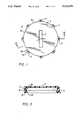
- FIG. 1is a top plan view of a fitment in accordance with the invention.
- FIG. 2is a vertical section through the fitment of FIG. 1 taken along the line II--II.
- FIG. 3is a vertical section through a screw cap with the fitment of FIGS. 1 and 2 retained in the cap in accordance with the invention.
- FIG. 4is a vertical section similar to FIG. 3 illustrating the cap of FIG. 3 screwed onto a container with the fitment of FIGS. 1 and 2 secured to the container.
- the fitment 1 and 2in accordance with the invention has a circular end wall 3 and a cylindrical sidewall 5 extending axially from the periphery of the end wall 3.
- the end wall 3has a dispensing slot 7 through which product can be dispensed from a container to which the fitment 1 is applied, as will be seen.
- Other types of dispensing openings other than the slot 7can be provided in the end wall 3, for instance, a small opening for dispensing a liquid a drop at a time, or a plurality of openings through which the contents of a container can be shaken.
- Spaced angularly around the outer surface 9 of the cylindrical sidewall 5are axially extending ribs 11.
- ribs 11which extend radially outward from the sidewall 5 are semicircular in cross-section.
- the ribs 11extend from the free edge 13 of the sidewall 5 to a point about even with the inside surface of the end wall 3. (See FIG. 2) In the exemplary fitment 1, there are 8 ribs 11 spaced 45° apart, although other numbers of ribs can be utilized.
- a thin flexible planar fin number 15Extending radially outward from each of the ribs 11 at the free edge 13 of the sidewall 5 and parallel to the end wall 3, is a thin flexible planar fin number 15. These fins 15 have a curved outer edge 17 which in the exemplary embodiment of the invention is semicircular. An annular bead 19 extends radially inward from the inner surface 21 of the sidewall 5 adjacent the free edge 13.
- the cap 23has a circular end wall 25 and an annular skirt 27 which has an internal helical thread 29 for securing the cap to a container.
- the fitment 1is pushed into the cap 23 with the fitment end wall 3 seating against the inner surface the cap end wall 25.
- the axial ribs 11center the fitment within the cap and produce a friction fit with the threads 29 on the cap.
- the thin flexible planar fin members 15extend radially outward into the thread 29. At least one of the fins 15 engages the top surface of the thread 29 to, together with the ribs 11, retain the fitment within the cap.
- the thread 29is helical and the free edge 13 of the sidewall of the fitment is square to the longitudinal axis 30 of the cap, others of the radial fins 15 extend into the gap 31 between the threads 29.
- the ribs 11extend outward to the thread 29, and thereby prevent the fitment 1 from tilting within the cap 23, the engagement of even one fin 15 with the top edge of the thread is sufficient to firmly retain the fitment 1 within the cap.
- the fins 15are flexible enough that they can bend to pass over the threads as the fitment is pushed into the cap, yet they are stiff enough to provide the required retaining force.
- the cap 23 with the fitment 1 retained within by the ribs 11 and the thin planar fins 15is applied as a unit to a container such as the bottle 33 as shown in FIG. 4.
- the bottle 33has a neck 35 terminating in a rim 37 which defines an opening 39.
- a helical external thread 41 complimentary to the internal thread 29 on the capis provided on the neck 35.
- Between the rim 37 and the external thread 41is a radially inwardly extending annular groove 43 in the outer surface 45 of the neck.
- the outer surface of the necktapers radially outward from the rim 37 to the groove 43, as shown at 47.
- the locking bead 19 on the fitment 1engages and is cammed outward by the tapered surface 47 and then snaps into engagement with the groove 43 to secure the fitment to the container neck.
- the fitmentWhen the cap 23 is unscrewed, the fitment remains attached to the container neck through the firm engagement between the locking bead 19 and the groove 43 in the container neck.
- the thin flexible fins 15threadedly engage the internal thread 29 on the cap 23 to provide a positive axial separating force between the fitment and the unthreaded cap to help separate the cap from the fitment.
- the fitment 1, in accordance with the inventionsecurely engages the cap 23 merely by pressing the fitment into the cap.
- the fitmentremains within the cap despite rough handling to which the assembly is exposed prior to application of the cap to a container. Still, the fitment is easily separated from the cap upon engagement with the container.
- the fitment 1can be easily and economically manufactured using straight draw molds.
- a decided advantage of the fitment 1 in accordance with the inventionis that it can be used with existing screw caps as no special features are required on the cap to retain the fitment temporarily in place.
Landscapes
- Engineering & Computer Science (AREA)
- Mechanical Engineering (AREA)
- Closures For Containers (AREA)
Abstract
Description
Claims (8)
Priority Applications (1)
| Application Number | Priority Date | Filing Date | Title |
|---|---|---|---|
| US07/652,793US5111978A (en) | 1991-01-16 | 1991-01-16 | Fitment retained in container closure |
Applications Claiming Priority (1)
| Application Number | Priority Date | Filing Date | Title |
|---|---|---|---|
| US07/652,793US5111978A (en) | 1991-01-16 | 1991-01-16 | Fitment retained in container closure |
Publications (1)
| Publication Number | Publication Date |
|---|---|
| US5111978Atrue US5111978A (en) | 1992-05-12 |
Family
ID=24618186
Family Applications (1)
| Application Number | Title | Priority Date | Filing Date |
|---|---|---|---|
| US07/652,793Expired - LifetimeUS5111978A (en) | 1991-01-16 | 1991-01-16 | Fitment retained in container closure |
Country Status (1)
| Country | Link |
|---|---|
| US (1) | US5111978A (en) |
Cited By (8)
| Publication number | Priority date | Publication date | Assignee | Title |
|---|---|---|---|---|
| US5184746A (en)* | 1992-02-26 | 1993-02-09 | Phoenix Closures, Inc. | Closure cap and fitment assembly |
| US5388731A (en)* | 1993-05-04 | 1995-02-14 | Continental Plastics, Inc. | Cap and dispensing fitment combination wherein the cap has retaining means engaging the fitment |
| US5680968A (en)* | 1995-05-03 | 1997-10-28 | Phoenix Closures, Inc. | Container closure system |
| US5730337A (en)* | 1996-05-10 | 1998-03-24 | Rxi Plastics, Inc. | Dispensing fitment with discrete snap bead members engaging container neck finish and assembly including fitment, container, and cap |
| US5954646A (en)* | 1997-04-02 | 1999-09-21 | Cds Technologies, L.L.C. | Tonometer probe with replaceable membrane |
| US20080203051A1 (en)* | 2004-05-21 | 2008-08-28 | Anton Dusel | Jar or Tin Lid |
| US10106302B1 (en)* | 2015-02-20 | 2018-10-23 | Christy F. Sorby | Beverage container pouring cap |
| US20250051070A1 (en)* | 2020-03-05 | 2025-02-13 | Richard John McCormick | Truly tamper-evident container |
Citations (11)
| Publication number | Priority date | Publication date | Assignee | Title |
|---|---|---|---|---|
| US2547590A (en)* | 1949-12-29 | 1951-04-03 | Wheeling Stamping Co | Container for condiments and the like and sifter cap therefor |
| US2696318A (en)* | 1950-03-27 | 1954-12-07 | Georges Achille Kihm | Closure sealing means for jars, bottles, and the like |
| US3339772A (en)* | 1964-11-16 | 1967-09-05 | Formold Plastics Inc | Container cap |
| US3823841A (en)* | 1972-04-13 | 1974-07-16 | American Hospital Supply Corp | Closure system for sterile medical liquid container |
| US4076152A (en)* | 1977-05-23 | 1978-02-28 | Owens-Illinois, Inc. | Fitment-retaining closure |
| US4187964A (en)* | 1978-08-01 | 1980-02-12 | Anchor Hocking Corporation | Combined closure cap and pour-out fitment |
| US4433800A (en)* | 1981-12-24 | 1984-02-28 | Top-Seal Corporation | Pouring fitment and closure assembly |
| US4475274A (en)* | 1982-07-07 | 1984-10-09 | Hunt-Wesson Foods, Inc. | Method of making and installing a pouring fitment |
| US4494682A (en)* | 1982-07-07 | 1985-01-22 | Hunt-Wesson Foods, Inc. | Pouring fitment with container and closure therefor |
| US4717034A (en)* | 1982-07-06 | 1988-01-05 | Owens-Illinois Closure Inc. | One-piece thermoplastic closure having press-on screw off structure including spaced vertical ribs in the skirt of the closure |
| US4773552A (en)* | 1986-11-03 | 1988-09-27 | Bodenseewerk Perkin-Elmer & Co., Gmbh | Closure for sample bottles |
- 1991
- 1991-01-16USUS07/652,793patent/US5111978A/ennot_activeExpired - Lifetime
Patent Citations (11)
| Publication number | Priority date | Publication date | Assignee | Title |
|---|---|---|---|---|
| US2547590A (en)* | 1949-12-29 | 1951-04-03 | Wheeling Stamping Co | Container for condiments and the like and sifter cap therefor |
| US2696318A (en)* | 1950-03-27 | 1954-12-07 | Georges Achille Kihm | Closure sealing means for jars, bottles, and the like |
| US3339772A (en)* | 1964-11-16 | 1967-09-05 | Formold Plastics Inc | Container cap |
| US3823841A (en)* | 1972-04-13 | 1974-07-16 | American Hospital Supply Corp | Closure system for sterile medical liquid container |
| US4076152A (en)* | 1977-05-23 | 1978-02-28 | Owens-Illinois, Inc. | Fitment-retaining closure |
| US4187964A (en)* | 1978-08-01 | 1980-02-12 | Anchor Hocking Corporation | Combined closure cap and pour-out fitment |
| US4433800A (en)* | 1981-12-24 | 1984-02-28 | Top-Seal Corporation | Pouring fitment and closure assembly |
| US4717034A (en)* | 1982-07-06 | 1988-01-05 | Owens-Illinois Closure Inc. | One-piece thermoplastic closure having press-on screw off structure including spaced vertical ribs in the skirt of the closure |
| US4475274A (en)* | 1982-07-07 | 1984-10-09 | Hunt-Wesson Foods, Inc. | Method of making and installing a pouring fitment |
| US4494682A (en)* | 1982-07-07 | 1985-01-22 | Hunt-Wesson Foods, Inc. | Pouring fitment with container and closure therefor |
| US4773552A (en)* | 1986-11-03 | 1988-09-27 | Bodenseewerk Perkin-Elmer & Co., Gmbh | Closure for sample bottles |
Cited By (8)
| Publication number | Priority date | Publication date | Assignee | Title |
|---|---|---|---|---|
| US5184746A (en)* | 1992-02-26 | 1993-02-09 | Phoenix Closures, Inc. | Closure cap and fitment assembly |
| US5388731A (en)* | 1993-05-04 | 1995-02-14 | Continental Plastics, Inc. | Cap and dispensing fitment combination wherein the cap has retaining means engaging the fitment |
| US5680968A (en)* | 1995-05-03 | 1997-10-28 | Phoenix Closures, Inc. | Container closure system |
| US5730337A (en)* | 1996-05-10 | 1998-03-24 | Rxi Plastics, Inc. | Dispensing fitment with discrete snap bead members engaging container neck finish and assembly including fitment, container, and cap |
| US5954646A (en)* | 1997-04-02 | 1999-09-21 | Cds Technologies, L.L.C. | Tonometer probe with replaceable membrane |
| US20080203051A1 (en)* | 2004-05-21 | 2008-08-28 | Anton Dusel | Jar or Tin Lid |
| US10106302B1 (en)* | 2015-02-20 | 2018-10-23 | Christy F. Sorby | Beverage container pouring cap |
| US20250051070A1 (en)* | 2020-03-05 | 2025-02-13 | Richard John McCormick | Truly tamper-evident container |
Similar Documents
| Publication | Publication Date | Title |
|---|---|---|
| US4394918A (en) | Screw cap with tamper-proof hold ring | |
| US5360127A (en) | Non-removable container closure | |
| US4562931A (en) | Pilfer-proof closure with tear-away holding claws | |
| US5676270A (en) | Threaded container torque retention system for use with a threaded closure | |
| EP0815027B1 (en) | Container with removal resistant closure | |
| EP0592580B1 (en) | Container-closure assembly | |
| US4752014A (en) | Tamper-evident child-resistant closure and container with same | |
| US4903828A (en) | Bottle closure cap for two-component packages | |
| US2911128A (en) | Spout and cap for a container | |
| US5388731A (en) | Cap and dispensing fitment combination wherein the cap has retaining means engaging the fitment | |
| US5915579A (en) | Container with tamper-evident and pre-lockable closure assembly | |
| US5551608A (en) | Closure assembly with tabbed liner | |
| US4320844A (en) | Releasable locking system | |
| US4337869A (en) | Closure assembly | |
| US20150191280A1 (en) | Tamper-evident container cap and neck finish | |
| US4801028A (en) | Closure device for a container having a cylindrical opening | |
| US6305579B1 (en) | Snap-on screw-off closure | |
| US20070034595A1 (en) | Bottle and cap closure apparatus with torque feature | |
| US6793082B1 (en) | Snap-on screw-off closure for use in combination with a container | |
| CN113226940A (en) | Safety cap bottle assembly | |
| GB2203729A (en) | Closure systems for containers | |
| US4457438A (en) | Tamperproof closure | |
| GB2114553A (en) | Security closure for blow-moulded plastics containers | |
| CA1164826A (en) | Load bearing closure | |
| US5111978A (en) | Fitment retained in container closure |
Legal Events
| Date | Code | Title | Description |
|---|---|---|---|
| AS | Assignment | Owner name:CONTINENTAL PLASTICS, INC., A CORP. OF DELAWARE, Free format text:ASSIGNMENT OF ASSIGNORS INTEREST.;ASSIGNOR:MENGEU, GARY L.;REEL/FRAME:005605/0511 Effective date:19910102 | |
| STCF | Information on status: patent grant | Free format text:PATENTED CASE | |
| FEPP | Fee payment procedure | Free format text:PAYOR NUMBER ASSIGNED (ORIGINAL EVENT CODE: ASPN); ENTITY STATUS OF PATENT OWNER: LARGE ENTITY | |
| AS | Assignment | Owner name:U.S. TRUST COMPANY OF CALIFORNIA, N.A. Free format text:SECURITY INTEREST;ASSIGNOR:CONTINENTAL PLASTICS INCORPORATED;REEL/FRAME:007414/0427 Effective date:19950331 | |
| FPAY | Fee payment | Year of fee payment:4 | |
| AS | Assignment | Owner name:RXI PLASTICS, INC., CALIFORNIA Free format text:CERTIFICATE OF AMENDMENT OF CERTIFICATE OF INCORPORATION OF CONTINENTAL PLASTICS INCORPORATED;ASSIGNOR:CONTINENTAL PLASTICS INCORPORATED;REEL/FRAME:008167/0099 Effective date:19960430 | |
| AS | Assignment | Owner name:U.S. TRUST COMPANY OF CALIFORNIA, N.A., CALIFORNIA Free format text:AMENDMENT TO SECURITY AGREEMENT;ASSIGNOR:RXI PLASTICS, INC.;REEL/FRAME:008869/0853 Effective date:19970919 | |
| AS | Assignment | Owner name:U.S. TRUST COMPANY, NATIONAL ASSOCIATION, CALIFORN Free format text:SECURITY AGREEMENT;ASSIGNOR:RXI PLASTICS, INC., FORMERLY KNOWN AS CONTINENTAL PLASTICS INCORPORATED;REEL/FRAME:009453/0685 Effective date:19980908 | |
| FEPP | Fee payment procedure | Free format text:PAT HLDR NO LONGER CLAIMS SMALL ENT STAT AS SMALL BUSINESS (ORIGINAL EVENT CODE: LSM2); ENTITY STATUS OF PATENT OWNER: LARGE ENTITY | |
| FPAY | Fee payment | Year of fee payment:8 | |
| AS | Assignment | Owner name:BANKERS TRUST COMPANY, NEW YORK Free format text:SECURITY INTEREST;ASSIGNOR:RXI PLASTICS, INC. A CORPORATION OF DELAWARE;REEL/FRAME:011314/0420 Effective date:20001005 | |
| AS | Assignment | Owner name:DEUTSCHE BANK TRUST COMPANY AMERICAS, NEW YORK Free format text:SECURITY AGREEMENT;ASSIGNOR:RXI PLASTICS, INC.;REEL/FRAME:013146/0773 Effective date:20020628 | |
| FPAY | Fee payment | Year of fee payment:12 | |
| AS | Assignment | Owner name:RXI PLASTICS, INC., CONNECTICUT Free format text:PATENT RELEASE;ASSIGNOR:DEUTSCHE BANK TRUST COMPANY AMERICAS, AS COLLATERAL AGENT;REEL/FRAME:016460/0938 Effective date:20050630 |