US5111410A - Motion analyzing/advising system - Google Patents
Motion analyzing/advising systemDownload PDFInfo
- Publication number
- US5111410A US5111410AUS07/543,127US54312790AUS5111410AUS 5111410 AUS5111410 AUS 5111410AUS 54312790 AUS54312790 AUS 54312790AUS 5111410 AUS5111410 AUS 5111410A
- Authority
- US
- United States
- Prior art keywords
- motion
- points
- trigger
- data
- advising
- Prior art date
- Legal status (The legal status is an assumption and is not a legal conclusion. Google has not performed a legal analysis and makes no representation as to the accuracy of the status listed.)
- Expired - Fee Related
Links
- 230000033001locomotionEffects0.000titleclaimsabstractdescription202
- 238000005259measurementMethods0.000claimsabstractdescription70
- 238000011156evaluationMethods0.000claimsabstractdescription29
- 230000015654memoryEffects0.000claimsdescription120
- 230000006399behaviorEffects0.000claims11
- 238000003745diagnosisMethods0.000abstractdescription8
- 238000004458analytical methodMethods0.000description24
- 238000012545processingMethods0.000description17
- 230000001133accelerationEffects0.000description15
- 238000000034methodMethods0.000description15
- 210000000707wristAnatomy0.000description15
- 238000005070samplingMethods0.000description13
- 239000000872bufferSubstances0.000description9
- 238000004364calculation methodMethods0.000description8
- 230000001960triggered effectEffects0.000description8
- 239000003086colorantSubstances0.000description5
- 238000001514detection methodMethods0.000description5
- 230000008569processEffects0.000description5
- 230000000694effectsEffects0.000description4
- 239000000284extractSubstances0.000description4
- 238000003384imaging methodMethods0.000description4
- 230000003287optical effectEffects0.000description4
- 230000002093peripheral effectEffects0.000description4
- 230000003044adaptive effectEffects0.000description3
- 238000010276constructionMethods0.000description3
- 238000000605extractionMethods0.000description3
- 238000007689inspectionMethods0.000description3
- 239000000203mixtureSubstances0.000description3
- 238000012986modificationMethods0.000description3
- 230000004048modificationEffects0.000description3
- 238000004088simulationMethods0.000description3
- 238000003860storageMethods0.000description3
- 230000002950deficientEffects0.000description2
- 238000010586diagramMethods0.000description2
- 238000005516engineering processMethods0.000description2
- 230000006870functionEffects0.000description2
- 239000003550markerSubstances0.000description2
- 238000012544monitoring processMethods0.000description2
- 239000000725suspensionSubstances0.000description2
- 239000002699waste materialSubstances0.000description2
- 241001465754MetazoaSpecies0.000description1
- 230000003542behavioural effectEffects0.000description1
- 230000008901benefitEffects0.000description1
- 230000015572biosynthetic processEffects0.000description1
- 230000008859changeEffects0.000description1
- 238000006243chemical reactionMethods0.000description1
- 239000002131composite materialSubstances0.000description1
- 239000013078crystalSubstances0.000description1
- 238000013461designMethods0.000description1
- 238000006073displacement reactionMethods0.000description1
- 238000009826distributionMethods0.000description1
- 230000007274generation of a signal involved in cell-cell signalingEffects0.000description1
- 230000005484gravityEffects0.000description1
- 239000004973liquid crystal related substanceSubstances0.000description1
- 238000000491multivariate analysisMethods0.000description1
- 238000003825pressingMethods0.000description1
- 230000026676system processEffects0.000description1
- 238000005303weighingMethods0.000description1
Images


Classifications
- A—HUMAN NECESSITIES
- A61—MEDICAL OR VETERINARY SCIENCE; HYGIENE
- A61B—DIAGNOSIS; SURGERY; IDENTIFICATION
- A61B5/00—Measuring for diagnostic purposes; Identification of persons
- A61B5/103—Measuring devices for testing the shape, pattern, colour, size or movement of the body or parts thereof, for diagnostic purposes
- A61B5/11—Measuring movement of the entire body or parts thereof, e.g. head or hand tremor or mobility of a limb
- A61B5/1126—Measuring movement of the entire body or parts thereof, e.g. head or hand tremor or mobility of a limb using a particular sensing technique
- A61B5/1127—Measuring movement of the entire body or parts thereof, e.g. head or hand tremor or mobility of a limb using a particular sensing technique using markers
- A—HUMAN NECESSITIES
- A63—SPORTS; GAMES; AMUSEMENTS
- A63B—APPARATUS FOR PHYSICAL TRAINING, GYMNASTICS, SWIMMING, CLIMBING, OR FENCING; BALL GAMES; TRAINING EQUIPMENT
- A63B69/00—Training appliances or apparatus for special sports
- A63B69/36—Training appliances or apparatus for special sports for golf
- A63B69/3623—Training appliances or apparatus for special sports for golf for driving
- A63B69/3629—Visual means not attached to the body for aligning, positioning the trainee's head or for detecting head movement, e.g. by parallax
- A—HUMAN NECESSITIES
- A61—MEDICAL OR VETERINARY SCIENCE; HYGIENE
- A61B—DIAGNOSIS; SURGERY; IDENTIFICATION
- A61B5/00—Measuring for diagnostic purposes; Identification of persons
- A61B5/103—Measuring devices for testing the shape, pattern, colour, size or movement of the body or parts thereof, for diagnostic purposes
- A61B5/11—Measuring movement of the entire body or parts thereof, e.g. head or hand tremor or mobility of a limb
- A61B5/1121—Determining geometric values, e.g. centre of rotation or angular range of movement
- A61B5/1122—Determining geometric values, e.g. centre of rotation or angular range of movement of movement trajectories
- A—HUMAN NECESSITIES
- A61—MEDICAL OR VETERINARY SCIENCE; HYGIENE
- A61B—DIAGNOSIS; SURGERY; IDENTIFICATION
- A61B5/00—Measuring for diagnostic purposes; Identification of persons
- A61B5/103—Measuring devices for testing the shape, pattern, colour, size or movement of the body or parts thereof, for diagnostic purposes
- A61B5/11—Measuring movement of the entire body or parts thereof, e.g. head or hand tremor or mobility of a limb
- A61B5/1124—Determining motor skills
- A—HUMAN NECESSITIES
- A61—MEDICAL OR VETERINARY SCIENCE; HYGIENE
- A61B—DIAGNOSIS; SURGERY; IDENTIFICATION
- A61B5/00—Measuring for diagnostic purposes; Identification of persons
- A61B5/72—Signal processing specially adapted for physiological signals or for diagnostic purposes
- A61B5/7271—Specific aspects of physiological measurement analysis
- A61B5/7285—Specific aspects of physiological measurement analysis for synchronizing or triggering a physiological measurement or image acquisition with a physiological event or waveform, e.g. an ECG signal
Definitions
- This inventionrelates to a system which measures, analyzes and diagnoses motions of humans.
- This inventionrelates, more particularly, to a system which displays in images the result of analysis of photographed golf swings and of comparison thereof with reference data, synthesizes images of swings with extracted data, displays stick patterns thereof for the reference of learners and/or obtains the difference between their motion and the target motion to diagnose their skills.
- This inventionfurther relates to the technology used in a system which generates signals for start, suspension or end of measuring, recording and displaying when the system measures motions for analysis.
- This inventionis applicable to a system for analyzing/teaching golf swings.
- Analysis/evaluation of motions of a player of sporthas usually been performed by an instructor. For instance, when a golf player practices swings, an instructor watches the player's motion and gives appropriate advices. If such an instructor is not available, the player records his swings in VTR or films and shows them later to the instructor for advise.
- the conventional systemsrequire additional manual operations or special sensors, and the trigger method thereof is not flexible enough. They cannot effectively detect some types of motions.
- This inventionaims to obviate these problems encountered in the prior art and to provide a motion analyzing/advising system which measures, analyzes, and evaluates motions in real time and outputs the result in display to diagnose them without the special sensors, etc. for triggering the system, and which can efficiently and effectively start the measurement operation from the image information of the motions.
- the first aspect of this inventionprovides a motion analyzing/advising system which can pick up motions of a golf player and displays the data of his movements at critical points in images with reference data.
- this inventionprovides a motion analyzing/advising system including a means which samples images of motions of a subject player and converts them to digital signals, a measurement means which extracts positional data from digitized image data for a plurality of motion points which are preset for motion analysis, and a display means which displays the result of measurement by the means, which is characterized in that the system further comprises a means which displays simultaneously the positional data at the motion points extracted by the measurement means together with the positional data of reference.
- the second aspect of this inventionprovides a motion analyzing/advising system which displays the movements of motion points in address superposed on the images of the motions of the subject player. More specifically, the system is characterized in that an image memory means for storing picked up images is provided so that positional data of at least one point may be displayed in the display means overlappingly with the images stored by the memory means. It is desirable to display the track of at least one motion point simultaneously with the images stored in the image memory means at preset timings.
- the third aspect of this inventionprovides a motion analyzing/advising system which picks up motions of a subject player and displays them in stick pictures by connecting points of his motions with line.
- the systemis characterized in that it further comprises a means which connects motion points with lines, and a means which displays linear components between these connected motion points for plural frames.
- the systempreferably includes a means which calculates by arithmetic operation the positional data of a point designated in advance out of the address data of surrounding points, and a means which displays in emphasis the line between the motion points at a time point designated based on the calculated value. It is also desirable to display the line between motion points together with the images stored in the image memory means.
- the fourth aspect of the inventionprovides a motion analyzing/advising system which picks up motions of a subject player, extracts data representing features of the motion, compares the data with the reference data and outputs the result of diagnosis based on the difference between the reference and the analysis subject.
- the motion analyzing/advising systemincludes a sampling means for sampling images of motions of a player and converts them into digital signals and a measuring means for extracting positions in coordinates for each point of plural motions which are preset for analyzing the motions, and is characterized in that the system further comprises a data calculating means for calculating data representing features of the motion out of the coordinates of each point extracted by said measuring means, a comparing means for comparing the thus calculated data obtained by the data calculating means with the reference data to obtain an evaluation value, and an output means for selecting one of the diagnoses prepared in advance depending on the thus obtained evaluation value.
- This invention systemincludes plural references and can compare the data of a subject player with those plural references.
- the systemmay further include a means which judges to which reference the player's data is closest. It may include a means to select plural references, and the comparing means can compare the data of the player with the thus selected plural references.
- the data calculating meansdesirably includes a means which can convert data of two or more points which have been already calculated into the data of the same time point as the reference data.
- the measuring meanspreferably includes a tracking means which designates areas including one or more motion points, moves the areas in the directions of the motion points respectively, and outputs the positional coordinates of the points.
- the motion to be diagnosedmay be a swing in golf playing.
- the fifth aspect of this inventionprovides a motion analyzing/advising system which can automatically execute the start, suspension and completion of operations without the necessity of providing an additional sensor.
- the motion analyzing/advising systemincludes a sampling means for converting images of the motions of a player into digital signals, a calculating means for calculating positional data in address for a plurality of motion points out of the thus converted image signals, and a measuring means for starting, suspending or finishing a measuring operation based on said positional data, and is characterized in that the system further includes a trigger detection means for detecting whether said motion points meet trigger conditions which are predetermined for starting, suspending or finishing the operation based on said address data.
- the trigger detection meanspreferably includes a means for detecting whether a motion point forms a predetermined angle in the reference direction, or whether the motion point forms a predetermined angle in the reference direction at a speed higher than the predetermined speed.
- the trigger detection meanspreferably includes a means for detecting if a motion point has passed a preset area in the address at a speed higher than the predetermined speed.
- the systemmay include an image memory means for storing images which are picked up with a trigger signal outputted from the trigger detection means in a plurality of frame memories, and the image memory means preferably includes a means which can overwrite images stored in a frame memory over the picked up images in superposition.
- the systemincludes one or more memories for storing the results of measurement and a means for prohibiting writing in the memory with a trigger signal outputted from the trigger detection means.
- the systempreferably includes an instruction means for instructing reversing if a mirror image is to be picked up or if a subject player is left-handed, a means for reversing an image, a means for reversing the positional data in the coordinates of motion points, or a means for reversing the trigger conditions or rotation.
- the motion analyzing/advising system of the first to the fifth aspects of the present inventionmay be packaged in a transportable case and may be provided with a battery for driving the means thereof.
- the systemtakes in motions of a subject player including his swings as image data, measures them, displays the measured data with images at any particular desired time point or displays stick pictures of his swings.
- the systemcan render diagnoses on various and different aspects depending on the reference, and therefore dispenses most suitable advice for each target model. As the system judges to which pattern the motion of a player belongs, and gives advices suitable to the particular pattern, it can teach any player in a most appropriate and effective manner depending on his motion type. Motions of a player including swings can be objectively evaluated irrespective of his build.
- the systemcan execute measurement adaptive to the content of the subject motions, and therefore can provide flexible and most effective measurement adaptive to the content of the subject without waste.
- the system according to the first to the fifth aspects of this inventionis compact in size and simple in use.
- the systemis therefore highly effective if installed at golf driving ranges or used for self-teaching.
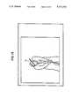
- FIG. 1shows a golf swing analyzing/advising system embodying this invention
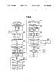
- FIG. 2is a block diagram of an embodiment of a processing system
- FIG. 3shows an embodiment of a timing signal generator useful in FIG. 2;
- FIG. 4shows the peripheral components of the CPU's of FIG. 2
- FIG. 5shows an embodiment of the operation panel of FIG. 1
- FIG. 6shows another embodiment of such an operation panel
- FIG. 7shows an arrangement for calculating motion points positional data
- FIG. 8shows a window signal generator
- FIG. 9shows an embodiment of a window
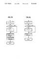
- FIG. 10is a flow chart showing the operation of an embodiment
- FIG. 11is a graph illustrating the height indication
- FIG. 12shows an example of motion tracks
- FIG. 13shows an example of a synthesized display of a track and an image
- FIG. 14is a flow chart showing the display operation of linear images
- FIGS. 15 and 16are flow charts showing the operation of FIG. 14;
- FIG. 17is an example of linear displays
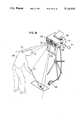
- FIG. 18shows another embodiment of this invention system
- FIG. 19shows the construction of a processing operation
- FIG. 20is a flow chart showing the operation of an embodiment
- FIG. 21is a flow chart showing the operation of an embodiment
- FIG. 22is an explanatory view to show the relation between motion points and motion data
- FIG. 23is an explanatory view to show interpolation
- FIG. 24is a flow chart showing the operation of an embodiment
- FIG. 25is a flow chart showing the operation of processing A in FIG. 24;
- FIG. 26is a chart showing the construction of an image switching calculating circuit
- FIG. 27shows a trigger signal output circuit
- FIG. 28shows an example of area designation
- FIG. 29is a chart showing the construction of a modified embodiment
- FIG. 30shows an embodiment of an indicator
- FIG. 31shows an example of measurement.
- This inventionis now described referring to an analysis of golf players' swings, but this invention is not limited to golf swings but may be applicable to analysis and instruction for baseball batting, gymnastics forms, etc.
- FIG. 1shows the structure of an embodiment of a golf swing analyzing/advising system according to this invention.
- the systemcomprises a TV camera 100 which picks up the swings of a subject player 1051, a lighting unit 101 appended to the TV camera 100, a processor 103 which inputs images taken by the camera 100 and processes data for image processing, measurement, diagnosis and display, a display for monitoring 102 which displays images, and an operation panel 104 provided with various switches for setting display modes or diagnostic conditions and lamps to indicate an operation mode.
- the body of the player 105 and a golf headare pasted with retro-reflective tapes to designate motion points P 1 (a golf club head), P 2 (the player's wrist), P 3 (his right shoulder), P 4 (his left head), P 5 (his head), and P 6 (his hip).
- the intensity of light reflected from the points P 1 through P 5is detected and measured to extract the positional data in an address for each point.
- the systemfurther includes a force plate 107 on which the player 105 stands when he starts his swings, and outputs therefrom are inputted at the processor 103.
- the force plate 107measures displacements of both the weight of the player and distribution of his weight between his feet, and further the fluctuation of these values supplementally to further enhance the effect of this system in evaluation and analysis of his motion.
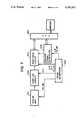
- FIG. 2is a block diagram to show the structure of the processor 103 which comprises a sampling circuit 200 which samples video signals inputted from a pick up unit 10 including a TV camera 100 and a light source 101 according to clock signals CLK from timing generator 206 and converts them into digital signals.
- Threshold circuit 205binarizes the output image signals from the sampling circuit 200, and a coordinate calculating circuit 250 calculates the position of a point P in accordance with the output from the threshold circuit 205.
- Address calculating circuit 250calculates the position in the coordinates of the point P based on the output from the threshold circuit 205.
- Frame memory 220stores image signals outputted from the sampling circuit 200 in the unit of a frame and has a capacity to store images of plural frames, while an image switching calculating circuit 210 controls initialization, renewal and saving of the frame memory 220 and selects images which should be stored therein.
- a graphic memory 240stores character/graphic data for linear display or the measurement result or the output or operation thereof.
- a CPU 260feeds timing signals to be stored in the frame memory 220, calculates the tracks of motion points out of the address data of the points, judges whether the preset trigger conditions are met, compares the data with a reference, and executes other various data processing and controlling operations.
- Memory 270saves the measured values and stores the positional data for the points P 1 through P 6 or the data calculated therefrom, and program memory 271 stores the processing procedures for the processor.
- An interface 272connects various peripheral parts such as an operation panel 104, an image synthesizer 230 which synthesizes the output images from the frame memory 220 or from the graphic memory 240 or both under the control of the CPU 260 and outputs the composed images to a display 300.
- Timing generator 206generates not only clock signals CLK for timing, but also horizontal synchronizing signals HD, vertical synchronizing signals VD, and address signals AX and AY of the images and feeds them to necessary circuits.
- the display 300 shown in FIG. 2is identical to the one for monitoring 102 shown in FIG. 1.
- the frame memory 220is an image memory which can independently control the input/output image signals in parallel, and which can record/ reproduce TV video images in pieces (or 3 frames).
- the frame memory 220is switched by controlling CPU 260. In order to save input images at a certain time point without updating the content of the frame memory 220, CPU 260 must control the system to invalidate writing-in signals on the input side thereof. This permits storage of images of an arbitrary frame and reproduction thereof on the display 300.
- FIG. 3shows the structure of a timing generator 206 which generates timing signals by dividing in frequency the clock signals generated by a crystal oscillator to generate horizontal synchronizing signals HD and vertical synchronizing signals VD of images, and counting these horizontal and vertical synchronizing signals to generate address signals AX and AY and supplies them to necessary circuits. More particularly, the clock signals CLK outputted from the oscillator 301 are applied to a position signal generator 302 which generates respective X-coordinate signals AX, and the outputs from the circuit 302 at the opposite terminal are outputted as horizontal synchronizing signals HD. The horizontal synchronizing signals HD are applied to another position signal generator 303 which generates respective Y-coordinate signals AY. The outputs from the circuit 303 from the opposite terminal are outputted as vertical synchronizing signals VD.
- the generators 302 and 303comprise shift registers.
- a screen as a wholemay form a coordinate system having 320 coordinates in the X (horizontal) direction and 240 in the Y (vertical) direction.
- the center of the address coordinates of a screenis set at (0, 0), the right upper end at (159, 119), and the right lower end at (-160, -120).
- the trigger conditionswhich will be described hereinafter may be designated in the address after conversion or may be designated in the actually measured length and converted later into the address values.
- FIG. 4which is similar as to its elements to FIG. 2, differently shows the peripheral equipment associated with the CPU 260 which is connected by buses respectively to the threshold circuit 205, a graphic memory 240, a positional calculator 250, an image switch calculator 210, a frame memory 220, an image synthesizer 230, a trigger signal output circuit 267, a memory 270 to save measured values, etc., a program memory 271, and an interface 272 which interfaces with various peripheral devices.
- To the interface 272are connected a switch 124 of the operation panel 104, a data input/output device 120 for IC card 121, a printer 122, a speaker 126, a microphone 128 and a sensor 130.
- CPU 260is connected to a window signal generator and to voice synthesizers, whenever necessary.
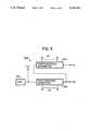
- FIG. 5shows an operation panel 104 according to the first through the fourth aspects of this invention.
- the panelis provided with lamps 141, 142, and 143 which indicate at which mode the operation is currently being conducted; i.e. "ready", “trigger” or “hold” at the left upper side of the panel.
- the panelis also provided with a switch 151 which shifts the panel between the mode to output the changes in motion points in graphs, tracks or composite images of tracks with images stored in the frame memory 220 or the mode to display them in linear images obtained by connecting the motion points with lines.
- Switch 152instructs shifting between the swing images A which is the subject of the analysis and the model images B.
- Switch 153instructs writing of the data within the saving area A of the result of the measurement into the saving area B for comparison purpose.
- Switch 154instructs reading in of the image data of the reference swing stored in the IC card 121.
- Switch 157instructs the print out of the result of the measurement, and switch 158 operates to start the shooting.
- FIG. 6Another embodiment of the operation panel is shown in FIG. 6.
- the panelis structured for trigger designation indicated in the fifth aspect of this invention.
- lamps 161, 162, 163At the upper end of the panel, there are provided lamps 161, 162, 163 to indicate the mode of "ready”, “trigger” or “hold”.
- Switch 164starts the shooting for measurement of a swing, a mode switch 165 to indicate whether the measurement is continuous or one-shot shooting.
- Switch 166designates trigger timings by angles for storing in the frame memory 220, and switch 167 indicates whether the mode of the frame memory 220 is "overwriting" or "single writing”.
- FIG. 7shows connections to the positional or coordinate calculating circuit 250. More particularly, the circuit 250 receives as input the window signals generated from the window signal generator 204 and uses the signals to calculate addresses of the motion points P 1 through P 6 . Although the threshold circuit 205 is omitted and signals are directly inputted from the sampling circuit 200 in this figure, the signals are inputted to the calculating circuit 250 via the circuit 205 as shown in FIG. 2. Alternatively, the system may be so structured that signals are calculated in the form of color signals without being converted into binary signals by the circuit 250.
- FIG. Bshows the structure of the window signal generator 204.
- the circuit 204accurately tracks the movements of plural points P to detect their positions in the coordinates even if the plural motion points are moving separately.
- the circuit 204may delete processing for addresses of the points other than the necessary ones for analysis to thereby reduce the amount of processing by the circuit 250 and CPU 260.
- the circuit 204is structured to output the window signals WS by multiplication of the signals in the direction X with the signals in the direction Y.
- the circuit in the direction Xincludes a counter 341 which inputs horizontal synchronizing signals HD and clock signals.
- Comparators (COMP) 342, 343compare the output of X signals from the counter 341 with X 1 , X 2 signals which set the frame addresses in the direction of X for the window signals fed from CPU 260.
- AND circuit 344outputs window signals in the direction X when X direction signals outputted from the counter 341 based on the multiplication with the outputs from the comparators 342 and 343 satisfying the condition X 1 ⁇ X ⁇ X 2 .
- circuit 204includes in the Y direction, a counter 345 which inputs the vertical synchronizing signals VD and clock signals CLK.
- Comparators 346, 347compare the Y direction signals with Y 1 and Y 2 signals fed from CPU 260.
- AND circuit 348receives the output from the comparators 346 and 347.
- the AND circuit 349receives the outputs from the AND circuits 344 and 348 to output the window signals WS to the circuit 250.
- FIG. 9shows an example of a window formed with such window signals.
- the area of the windowmoves along the movement of the point P in the same direction.
- the window areais moved sequentially in the direction of the movement of the point P obtained by CPU 260.
- FIG. 9The example shown in FIG. 9 is the case where only one window is formed, but in practice addresses are calculated for plural motion points P 1 through P 6 , and hence the FIG. 8 window signal generator 204 would be in number equivalent to the number of motion points.
- the explanation on the operation of this embodimentcomprises three parts; (1) the first part concerns the first to the third aspects of this invention and, more particularly relates to the operations of picking up the golf swings and measuring them, displaying the movements of the motion points in graphs, tracks and linear displays as the result of the measurement in composition with the images stored in a frame memory; (2) the second part relates to the fourth aspect of this invention or the operation to compare the obtained data with the reference data stored in advance in the system to obtain the distance from the reference, and to output the result of various diagnoses in voice according to the distance; and (3) the third part relates to the fifth aspect of this invention or the operation to trigger the measurement or the operation to collect data, to save images or suspend or complete measurement when predetermined conditions for trigger are met.
- a swing motion of a golf playeris assumed herein to be diagnosed by the following four displays.
- the first oneis a graph display on a display 300 having the time on the horizontal axis and changes in height on the vertical axis in order to show the positional data of the picked up swinging form of the player and the difference from the reference model.
- the secondis the display of the track of motion points in combination with the tracks of model forms.
- the thirdis the display of a motion point track of the player in combination of the image of the swing which is most approximal thereto at a certain given time, such as impact, of those stored in the frame memory 220.
- the fourthis the display on the display unit 300 of a linear pattern formed by connecting motion points with lines to show the swing of the player in stick patterns. For this operation, an image switch calculator 210 is not used.
- These displaysmay be selected by a switch on the operation panel 104 (FIG. 5).
- the start switch 158By turning on the start switch 158, the system is actuated and the TV camera 100 (FIG. 11) of the unit 110 (FIG. 2) picks up the images of a swing of a subject player.
- retro-reflective tapesare pasted on the pertinent locations of the body of the player for analyzing his motion and these locations are denoted as the motion points P 1 through P 6 .
- the attachment of retro-reflective tapesincreases luminance on the points P, to P to facilitate extraction from the images. Extraction of the motion points P may be executed by colors. In such a case, a color TV camera and a color extraction circuit in the number equivalent to the maximum points of the output color image should be used.
- a strobeas the light source 10 for the TV camera 100 in order to capture the motion, and to flash the light in synchronization with video signals.
- a shutter cameramay be used as the TV camera 100. In such a case, it may replace the strobe and is lit constantly as the light source.
- the imaged swings of the playerare converted into digital signals by the sampling circuit 200 (FIG. 2).
- image data in the form of digital signalsare stored in the frame memory 220.
- the digital signalsare binarized by the threshold circuit 205 and inputted at the circuit 250.
- the circuit 250then converts the binary signals into x-coordinate signals and Y-coordinate signals, out of which positional signals related to the points P 1 through P 6 are taken in by the CPU 260 to calculate data for these points.
- the image signals stored in the frame memory 220are stored while plural sheets of the frame memory 220 are updated.
- the images at particular timings as instructed by CPU 260 such as the timing of impactare held.
- a sensormay be provided so that the timing is set with the output from the sensor for saving or calculating the data in the frame memory 220.
- FIG. 10is a flow chart to show the processing in the swing diagnosis by the processor 103.
- the start switchis turned on, image signals are inputted and stored while the frame memories are updated, and the measured values are stored while the memory 270 is being updated and the graphic memory for display 240 is cleared (S11, 12, 13) at the same time.
- Modes of display of the result of the diagnosisare selected from the graphic display of the changes in height of motion points (S20), display of the tracks of the points (S21), display of composed images of the tracks of the points and the swings stored in the frame memory 220 (S22), and display of the stick picture formed by connecting points with lines (S23). If data must be held, the data are stored in IC cards (S24, 25). Those four modes are respectively or sequentially displayed.
- the address data for the point P 5 inputted from the circuit 250have been stored in the memory 270 as X- and Y-coordinate data. Out of the stored data, the changes in the height of the points of the values on the Y axis are extracted for the time from the start to the end of the swing, and are chronologically displayed in a graph. The graph is stored in the graphic memory 240. Simultaneously, changes in the height of the model swinging at the point P 5 are plotted chronologically in a graph and stored in the graphic memory 240.
- the output from the graphic memory 240is displayed in the display unit 300.
- the two graphsare displayed in different colors so as to facilitate understanding of the viewer 105.
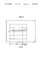
- An example of such displayis shown in FIG. 11.
- the displayed graphshows positional changes of the head of a player for 1.5 sec. before the impact and for 0.5 sec. after the impact.
- the upper lineindicates the positional change of the head of a skilled golf player while the lower line indicates that of a beginner.
- the graphclearly indicates that the beginner tends to move his head downward. Golfers can easily understand where their weak points lie by looking at the graph which indicates the reference model and their own movement.
- the graphmay be shifted horizontally so that the time of impact becomes the origin with deviation from the reference for better understanding by the viewer.
- the operation to display the tracks of the pointsis now described.
- the positional data for the points P stored in the memory 270are extracted, and the track thereof is stored in the graphic memory 240 based on the X- and Y-coordinates.
- the data for reference pointsare stored in the memory 240 in the form of a locus.
- the two dataare displayed in the display unit 300 via the circuit 230.
- the two locishould be displayed in different colors to facilitate understanding by the viewer.
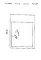
- FIG. 12An example of the display is shown in FIG. 12.
- the displayshows in the form of loci the positional changes of the player's head at the point P 5 .
- the time of the impactis displayed in a light color.
- T1denotes the locus of the movement of the player
- T2the locus of the reference model.
- the graphmay be plotted with the origin placed at the impact or the addressing time so as to show the data of the subject overlapping those of the reference model. If the locus before and after the trigger are plotted in different colors, understanding by the viewer is further facilitated.
- the reference datamay be the data of a professional golf player, the data of the subject player one month or one week before or the data taken when he practiced on his own. Such reference data is stored in the IC card 121 and the data may be inputted from the IC card input/output unit 120. Conversely, the measured data of his swing may be stored in the IC card 121 for use in the next analysis. IC card may be replaced by a floppy disc or the like.
- the frame memory 220stores image signals while updating the frames.
- the frame memory 220stores and holds the frames which should be displayed later such as at triggered time when certain trigger conditions are met or the output from the sensor is received.
- the data on the tracks at the point Pare also stored in the graphic memory 240.
- CPU 260controls the system to display on the unit 300 the images of a swing stored in the frame memory 220 together with the locus stored in the graphic memory 240.
- the image synthesizer 230is used to compose the two images and display the same on the unit 300.
- FIG. 13An example of the display is shown in FIG. 13.
- the locus of the point P' or the head of the playersis displayed together with the images at the time of impact.
- FIG. 14shows a flow chart of the linear display mentioned above.
- the linear displayrequires operations to compose the images and the linear images stored in the frame memory 220 and to display the two simultaneously. If linear image display alone is needed, the operation of storing and reproducing in and from the memory 220 may be omitted.
- the systemis initialized first (S31) to secure the memory capacity for 2 seconds or 120 frames in the memory 270 which is to store the measured values.
- the letter Hdenotes the duration of time for prohibiting updating of the frame memory after the trigger signal (impact time) and herein it is set at 180 frames (3 sec.)
- the points P 1 , P 2 , and P 3are connected by linear components and the screen is cleared.
- a trigger stateis displayed, while at S42 the state of hold is shown by a lamp.
- the processing shown in FIG. 15is executed at the step S33.
- the n-th memory 270is updated for holding the measured values while the frame memory 220 is being updated at the step S33.
- the n-th memory 270 of FIG. 16is updated to wait for a swing at a trigger state.
- the systemis updated for the number of updated frames of the memory after the trigger by the steps S36 through 39. This achieves holding of the frame at the time of trigger.
- linear images obtained by connecting points P 1 , P 2 , and P 3 with linesare displayed.
- images at the impact time stored in the frame memory 220are displayed in composition with the linear images in the unit 300.
- the image signals stored in the frame memory 220are controllably held for a predetermined duration of time once a trigger is issued.
- the images stored in the frame memory 220are composed with the linear images obtained by connecting the points P 1 through P 3 with lines and displayed.
- the stick pictures for the points P 1 through P 3may be displayed.
- An example of a stick picture for the points P 1 through P 3is shown in FIG. 17, but not all the linear components for all frames are shown. Only the selected lines are shown in order to simplify the description.
- the addressmay be calculated from the coordinates close thereto for the necessary angle or the time by calculation of interpolation or linear approximation which will be described hereinafter.
- FIG. 18shows an embodiment of this invention's motion analyzing/advising system which is portable.
- the systemis packaged in a portable case 112 and comprises an imaging unit 110, a display unit 102', an operation panel 104, a printer 122, a speaker 126, a microphone 128 (behind the speaker), and an IC card input/output unit 120.
- Case 112also includes a processor and an operation panel like items 103, 104 in FIG. 1.
- a plane display unitsuch as a liquid crystal display unit may be used as unit 102'.
- the systemis provided with a battery power source for actuation.
- Unit 130is a light sensor.
- a subject playerWhen in use, a subject player stands at a position facing the system, and swings. His motions are imaged by an imaging unit for measurement, and the measurement result is displayed on the display unit upon demand, outputted by a printer or stored in an IC card.
- the trigger moment or the time of impactis detected by a sensor 130 provided at a position suitable for addressing, and a start switch is attached to the sensor.
- triggeringmay be detected when the trigger conditions are satisfied, it is not always necessary to provide the sensor.
- this systemis actuated by a battery, it can conveniently be used at golf ranges or on the golf courses where no commercial power source is available.
- Swings in images taken by VTRmay be analyzed by this invention system.
- a VTR unitnaturally may be used in place of a TV camera as the imaging unit 110.
- the speaker 126outputs voices or buzzing sound to indicate whether the trigger has been applied normally. This also functions to notify the end of a measurement.
- the microphone 128may be used to indicate in voice the start of measurement instead of pressing the switch for start, but in this case provision of a voice sound processor is necessary.
- the speakermay be used to output the result of the analysis of a swing (which will be described hereinafter) and a speech synthesizer is needed for this case.
- FIG. 19shows the structure of the processing steps.
- the unitincludes an input means 21 which inputs data of a swing picked up by the imaging unit 110.
- Swing measuring means 22extracts the data in the address of the point, which is a base for the analysis, by means of image processing technique.
- Data calculating means 23extracts and calculates the speed, acceleration, angular speed or angular acceleration for each point out of the thus obtained positional data and obtains data groups matched with the reference.
- a comparison reference holding means 24holds data for plural references and a comparison/judgement means 25 compares the calculated data with the reference data.
- Post-processor 26selects diagnosis results for a particular reference out of the holding means 24 depending on the result of comparison and processes them for output in voice or image in the display, and an output means 27 outputs the result in image or voice.
- a subject playerselects a reference before actually starting the analysis by manipulating a switch 124 (FIG. 4).
- a switch 124FIG. 4
- hemay select a reference by inserting an IC card 121 or a similar memory card into an IC card input/output unit 120 which is provided as an exterior memory input/output unit for the unit 103.
- Data of the swings played by plural and different types of professional golf playersare available as the references. For instance, a series of patterns comprising data groups are prepared to record analysis of the swings of such famous professional players as Tsune Nakajima, Masashi Ozaki, and Isao Aoki.
- the measuring operationis started first; a swing of a subject player is picked up by the unit 110 including a TV camera 100 to measure the swing and to store the measured data (Step S52).
- the characteristic datais calculated out of the measured data (Step S53).
- the characterized datais compared with the selected reference data (Steps S55-1 through S55-n). The difference from the reference is obtained, and advices adapted to the references are loaded from the memory (Steps S56-1 through S56-n) and converted into voice for output (Step S57). If further analysis is required, processing is repeated.
- Step 51whether the measurement has been started is decided and at the step S58 whether it has ended is decided.
- CPU 260processes the measurement and storage of a swing, and the calculation and comparison of the data performed at the steps S52 -S56.
- FIG. 21is a flow chart to show the details of the processing at the step S52.
- the positional data for each pointare calculated from the address signals of the points inputted from the circuit 250. More particularly, the centers of gravity are respectively calculated for the points P 1 through P 6 .
- X- and Y-coordinates inputted from the circuit 250are added for each point.
- the obtained addressesare designated as the coordinates for the points and stored in the memory 270.
- the positional addresses of each point and positional addresses defining a window with the point at the center thereofare outputted to the window signal generator 204 in order to align the window covering the measured data therein with the position of the point in a preceding image.
- the positional address to define a windowmay be predicted by comparing the preceding position of a point with the current position thereof and outputted to the circuit 204.
- the measurement operationis conducted for all the images from the start point to the end point, and the extracted addresses indicating the movement at each point are stored in the memory 270.
- the measurement of necessary datais started from the trigger point for measurement.
- the trigger pointmay be determined as the time when the club head reaches the highest position or the time when the angle of the club becomes 60° against the vertical direction or the time when the club passes over the head of a player from right to left. It may also be determined timewise such as the measurement should be triggered one second after the start button is pushed.
- the end pointis the time point when all the data necessary for analysis of a swing have been obtained, and may be any point during the follow-through after the impact.
- the end pointis not necessarily set, and the operation may end when a predetermined duration of time has lapsed after the trigger point.
- the dataare calculated to extract features of the swing of the player.
- the dataare the speed of the club head VP 1 , the angle of the club ⁇ 1 , the angle of the arm ⁇ 2 , the angular speed of the club ⁇ 1 , the angular speed of the arm ⁇ 2 , the angular speed ratio ⁇ 1 / ⁇ 2 , the angular acceleration of the club ⁇ 1 , the angular acceleration of the arm ⁇ 2 , and these data are calculated from the addresses of the points P 1 through P 6 , and the obtained data are formulated in time series of sampled images in a table such as Table 1 below. The table shows only the data on the club head address P 1 , the wrist address P 2 and the shoulder address P 3 .
- FIG. 22shows the relation between the points and data.
- DDT2angular acceleration of the arm.
- Reading in of image data of the motion of the subjectstarts from the trigger point, but as the system does not sample and output the impact time when the subject hits the ball or the acceleration reaches its peak, it is necessary to obtain by arithmetic calculation the data at the peak for comparison purpose.
- the datapreferably are taken at the time point coinciding with the reference data time point as the reference data should be those existing within a given time period or an angular interval from the impact time and at the peak value.
- Timing of a swingmay be judged good or bad by comparing the time or the address point of the peak speed of the head with those at the impact. It is also possible to judge whether or not the peak moves away from the center of revolution of the swing radially by comparing the peak of the angular acceleration of the arm with the peak of the angular acceleration of the club, a swing may be evaluated by obtaining timewise positions and peak values.
- the peak time in angular speedmay be calculated by the following equation if it is assumed that the club angular speed D T1 represents the maximum value. ##EQU2## Similarly, the peak times may be obtained for the arm angular speed DT 2n , the club angular acceleration DDT in , the arm angular acceleration DDT 2n .
- the peak value at the peak timemay be obtained by interpolating the data before and after the time. The interpolation of the data may be performed by inserting the data of these three points by parabola approximation, circular approximation or linear calculation.
- the data as the reference datamay be calculated similarly by interpolation or linear approximation.
- the obtained datawill subsequently be compared with the reference data.
- the data on the characteristic motions of a swing by a professional golferare prepared in advance in the form corresponding to the above Table 1.
- the selected reference dataare read out and the distance between the reference data and the subject data is measured.
- the distancesshould be obtained respectively at each comparison point for the speed of the head, arm angular speed, acceleration, angular acceleration, etc., and the differences of each data are calculated to obtain the square sum thereof. This allows one to judge how far the data of a swing by the subject is from the reference data.
- the distance of the subject data from the reference datamay differ depending on the reference selected and on the point prioritized, and therefore the data should be weighted. For instance, a subject who selected Masashi Ozaki, the professional golfer, may prioritize the distance in analysis. Therefore, the data relating to the distance should be weighted more. On the other hand, a subject who selected as his model Isao Aoki may prioritize the motion of his wrist, and more weight should be given to the movement of his wrist data.
- parametersmay be selected from the data collected from the swings of a particular golfer or of plural professional players using various statistic methods such as multivariate analysis.
- Advicesare prepared in advance corresponding to the respective references, and therefore an advice suitable to the selected reference will be given. This is because the check items differ depending on the model professional golfer. For instance, if the model is selected to be Masashi Ozaki, the items such as the swinging motion of the arms or twisting of the body will be checked, and advices with an emphasis on these items will be given.
- Table 2shows as reference the angular speed m 1 , and the head speed at the impact time m 2 of Isao Aoki and Masashi Ozaki, two professional golfers.
- Table 3shows weights ⁇ of those two golfers.
- a comprehensive evaluation point Ais obtained by the following equation. ##EQU3## If Isao Aoki is selected as the reference, the point is 81 while if Masashi Ozaki is selected, it is 61. An advice such that "Your total point is 81. It is almost close to the target swing. You had better turn the wrist back a bit quicker. The drive distance is long enough" will be given to the subject who selected Aoki. The subject who selected Ozaki is given an advice such that "Your total point is 61. You have a long way to reach the target. You had better swing your hip faster and with all your force".
- the last phrase in the advice stringrelates to those on the wrist and the hip of the player, and are given in Table 6 depending on the comparison with the angular acceleration at the impact.
- the advice obtained by comparing with the referenceare converted into voice signals by a converter, and outputted from the speaker 126 for the subject. Alternatively, they may be displayed in characters or images on the display unit 300.
- Thisis determined by selecting a group of data suitable for judging classification of the swing such as the peak value or chronological interrelation thereof and comparing the group of data with the reference data selected similarly rather than comparing all the data.
- An evaluationis determined by extracting the difference between the subject data and the data of the closest reference pattern to output a suitable advice thereto.
- the plural referencesmay include bad examples in addition to the model performance so that the swing of the subject is first judged to determine to which pattern it belongs, and then the type under which his swings fall is outputted with suitable advices.
- the subject datamay also be compared with other data.
- evaluationmay be given by comparison of the head speed at the peak value with that at impact, or the maximum club angular speed with the club angular speed at impact time.
- the time relationsuch as the peak value of the speeds of the impact, wrist or arm reaches the peak at what chronological relation with the impact time may be used for obtaining the evaluation.
- any reliable data to evaluate the swingmay be used.
- the processor 103may be provided with an output/input section connected to an outer memory, and the data and result of diagnoses are stored in the memory so that every time an analysis is made for a subject player, the data of the time may be compared with the previous data and evaluation. The result of the comparison will be outputted in phrases such as "Your swing of the arm is better than the last time, the turn of the wrist is also better than the last time".
- the operation according to the fifth aspect of this inventionis described below.
- the operationis described by referring to a case where memory timing for the frame memory is extracted out of the images of a golf swing of a desired state in the frame memory or the address data and images are held for reproduction.
- an angle Q in the frame memory 220is designated in the direction vertical to the golf club so as to hold images of a downward swing at the time of impact.
- the angle Qis set by an operation panel 104, and more particularly by a switch 1166 thereon indicating trigger conditions.
- FIG. 24is a flow chart to show the operation in measurement of a swing of a golf player.
- the systemis first initialized (S61). More specifically, 3 is set for the number N in the frame memory 220. For H which is to be set for the duration of prohibiting trigger signal generation and in this case 180 frames or 3 sec. is set.
- the state of waiting for trigger (ready)is displayed by a lamp, at the step S65 the state of trigger generation, and at the step S70, the state of holding.
- the processing shown in FIG. 25is conducted. More specifically, it is controlled to wait for a swing motion satisfying the trigger conditions while sequentially updating the frame memory 220.
- the frame memoryis updated for the amount after the trigger by the operations of the steps S66 through S69.
- Q Ldenotes the angle Q of the club at the time l, X L the X-coordinate at the time l of the motion point P 1 , Q L-1 the angle of the club of the time 1/60 sec. before the time l, X L-1 the X-coordinate of the motion point P 1 at the time 1/60 sec. before the time l, and ⁇ the speed reference value at the point P 1 .
- the reason why the condition of the speed of the club ⁇ is included in the trigger conditionsis because it should be differentiated from the case where the subject swings the club lightly for trial. It may be the speed of 15 (m/s) or any speed so far as it can be differentiated from a trial swing.
- Y Ldenotes Y-coordinate of the point P 1 at the time l
- Y L-1the X-coordinate of the point P 1 at the time 1/60 Sec. before the time l
- ⁇the speed reference value at the point P 1 .
- image signals stored in the frame memory 220are held for a prescribed duration of time.
- FIG. 26shows the structure of an image switch calculation circuit 2110. The operation thereof is now described.
- the circuit 210may be switched between modes for single writing or superposition in the frame memory 220 to switch the input image signals therein. For superposition, two image signals inputted from the sampling circuit 200 and from the frame memory 220 are overlapped in output to the frame memory 220. More particularly, the circuit 210 comprises a comparator 3511 which compares the luminance of the image signals from the circuit 200 with the image signals from the frame memory 220. Buffer 352 buffers the image signals from the circuit 200, while buffer 353 buffers image signals from the frame memory 220. Switch 354 switches from the image signals from the sampling circuit 200 to the output image signals from the buffers 352 and 353 depending on the control from CPU 260.
- the buffers 352, 353output the input from comparator 351 only when selected, and provide a high impedance output when not selected.
- the output from the buffer 352is selected, while when it is smaller, the output from the buffer 353 is selected.
- the switch 354is selected depending on a singleshot mode or an overlapping mode of the frame memory 220.
- the switch 354conducts initialization of the frame memory 220 when the contact a on the side of the sampling circuit 200 is selected while it updates the frame memory 220 when the contact b is selected on the side of the buffers 352, 353.
- the contact ais fixed.
- FIG. 27shows the structure of a trigger signal output circuit 267 (FIG. 4) wherein the output trigger signal is obtained by writing data from CPU 260 to IC 371 at the timing aligned with the ON/OFF operation of the trigger display lamp 162 on the panel 104.
- IC 371is a D type flip-flop which latches on TTL. The above mentioned data may be inputted using a part of the data bus of CPU 260 while CS is obtained by decoding address signals.
- IC 371may be SN74LS74A produced by T.I.
- a memory 270is assumed to be structured in a manner to hold 10 sets of the coordinates for the points P 1 , P 2 and P 3 , and the trigger conditions are set to satisfy the following three conditions simultaneously.
- two areasmay be set on the coordinates as shown in FIG. 28, and two conditions are set as below.
- Condition 31the point P, exists within the rectangular area F having vertices at points (x 1 , y 1 ) and (x 2 , y 2 )
- Condition 32the point P 1 exists within the rectangular area G having vertices at points (X 1 , Y 1 ) and (X 2 , Y 2 )
- the trigger conditionis set that within two frames the condition 32 exists after the condition 31 is not met any more.
- the measurementmay be triggered for a swing. More complicated operations may be performed if the trigger conditions are set using logical sum or multiplication or patterns of satisfaction/dissatisfaction.
- the trigger conditionsmay be set by the number of times certain conditions are satisfied.
- trigger conditionsmay be set as follows. Use of a mirror can reduce the space required for installing this system quite advantageously, but the images outputted to the display 300 are opposite of those described above, and therefore the trigger conditions should be reversed.
- the presence/absence of a mirroris set by a switch on the panel 104 and CPU 260 reads the information to reverse the address signal AX in the horizontal direction and the symbols of the X-coordinates for the points P 1 through P 3 .
- a similar operationis performed for a left-handed subject; the information is fed by operating a switch on the panel so that the information may be read in by CPU 160 which controls the system to reverse the symbols of the X-coordinates and the angles.
- the fifth aspect of the present inventionis now described in respect of a modified embodiment.
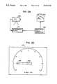
- This modificationis related to an inspection system for analyzing revolution of a tachometer.
- ignition signals simulated from a simulation signal generator 430are used to drive a meter 440, and the movement thereof is imaged by a TV camera 420 so as to inspect the meter 440.
- a pointer of the meter 440 or the subject of the inspectionis provided with markers 474 and 475 respectively at the tip end and the center of rotation, and the address positional data of the markers 474, 475 are calculated by a coordinate calculator.
- the rotational angle 8 of the pointerbecomes constant and reaches a prescribed angle, or in other words the marker 474 marks a prescribed angle from the marker 475, for instance 90 degrees from the vertical direction, the system is triggered, and the movement of the pointer is measured for analysis of features.
- a trigger signal generatoris additionally provided to give trigger signals for starting the measurement to the measurement system 410 and the simulation signal generator 430 so that the generator 430 starts output of simulated signals with the trigger signals to take in the movement of the meter by the unit 410.
- the speed or the smoothness of the pointer in the metermay be automatically measured.
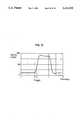
- FIG. 31shows an example wherein the meter 440 is moved stepwise between 0 rpm and 3000 rpm and the dynamic characteristics thereof are measured. The measurement is triggered when the following condition 41 is met wherein t is the time and Q the angle.
- the unitis triggered at the time point when the pointer passes the gauge of 1000 rpm or forms the angle of 90° from the vertical direction, and data before and after the desired time point will be taken in for measurement.
- Thisenables the circuit 430 to control the simulation of the signals irrespective of the measurement unit, making design of the total system easier. This also enables analysis of the relation between the control signal simulated by the circuit and the actual movement of the meter by taking in the data with the trigger signals.
- the structure mentioned abovemay be applicable to the system for inspecting for acceptance the products which are transported on a conveyor belt by setting various trigger conditions depending on the features of the products.
- This systemis also applicable to the behavioral analysis of animals.
- the trigger conditionsare set for starting measurement in the above embodiment and the modification according to the fifth aspect of this invention, it may be set for ending or suspending. For instance, an operation which cannot possibly occur during the measurement is set as a trigger condition, and if this condition is detected, the system is controlled to suspend the measurement operation and to return the procedure to the initial ready state or the state to receive trigger signals. If a condition to end the measurement is set, the measurement operation can be controlled for completion when this condition is detected.
- Trigger conditionsmay be set in a plural number: i.e. conditions to start, suspend and end are set in advance and when any of them is detected, it is controlled accordingly. The effect of the measurement operation is therefore enhanced.
Landscapes
- Health & Medical Sciences (AREA)
- Life Sciences & Earth Sciences (AREA)
- General Health & Medical Sciences (AREA)
- Engineering & Computer Science (AREA)
- Heart & Thoracic Surgery (AREA)
- Oral & Maxillofacial Surgery (AREA)
- Physics & Mathematics (AREA)
- Physiology (AREA)
- Biophysics (AREA)
- Pathology (AREA)
- Physical Education & Sports Medicine (AREA)
- Biomedical Technology (AREA)
- Dentistry (AREA)
- Medical Informatics (AREA)
- Molecular Biology (AREA)
- Surgery (AREA)
- Animal Behavior & Ethology (AREA)
- Public Health (AREA)
- Veterinary Medicine (AREA)
- Closed-Circuit Television Systems (AREA)
Abstract
Description
This invention relates to a system which measures, analyzes and diagnoses motions of humans. This invention relates, more particularly, to a system which displays in images the result of analysis of photographed golf swings and of comparison thereof with reference data, synthesizes images of swings with extracted data, displays stick patterns thereof for the reference of learners and/or obtains the difference between their motion and the target motion to diagnose their skills.
This invention further relates to the technology used in a system which generates signals for start, suspension or end of measuring, recording and displaying when the system measures motions for analysis. This invention is applicable to a system for analyzing/teaching golf swings.
Analysis/evaluation of motions of a player of sport has usually been performed by an instructor. For instance, when a golf player practices swings, an instructor watches the player's motion and gives appropriate advices. If such an instructor is not available, the player records his swings in VTR or films and shows them later to the instructor for advise.
There has been proposed a memory means which can pick up swing forms of a player in VTR or in time lapse shooting; for example, a technology which picks up swing forms of a player by an electronic-still-camera and reproduces/displays them in the unit of frames to viewers.
There has also been proposed in the prior art a system for evaluating golf swings which measures the speed or direction of a golf ball or the impact speed of a club head and digitally displays the result in numerical figures.
Although there is also available a system which picks up swings in image and processes them, there has heretofore been no system which can analyze the captured swings in real time, compare them with a reference, and give suitable advises. When a golf player wishes to practice by himself without an instructor, he cannot achieve an effective result because he is without valuable advises. Unless he is given timely advises while he still remembers his motion, his practice cannot attain effective result. If he is given instruction after a time lapse, learning effect cannot be fully achieved.
Even if a player is shown his swings in image which are reproduced in the unit of a frame, an amateur player merely sees his motions which he cannot evaluate properly and hence cannot benefit from the display. Data in numerics are not useful in evaluating his motions, since such display of numerical values alone does not show his whole actions nor diagnose his swings. All these conventional systems are therefore defective as a teaching system for golf swings.
Moreover, these prior art systems measure motions of a player by means of switches. More particularly, measurement is taken for 3 seconds after a switch is turned on; this takes unnecessary measurements before and after a motion. In order to eliminate such waste, the system requires manual operation by an assistant other than the player himself for turning on the switch. The conventional system, moreover, cannot precisely catch motions if they are very quick.
There has also been proposed a method of starting measurements by means of a sensor such as an optical limit switch. For instance, there has been proposed a method which employees a lamp and an optical limit switch and which uses signals generated when a golf club crosses the path as trigger signals for measurement. But this method is defective in that an optical limit switch should be provided at a designated location, and that the position of such switch should be changed depending on the type of motions to be measured such as the motion of impact and the motion of follow-through. The system therefore is not adaptive to the subject of measurement or the degree or type of motions. It is also difficult to use the system with an optical limit switch to measure complicated movements.
As stated above, the conventional systems require additional manual operations or special sensors, and the trigger method thereof is not flexible enough. They cannot effectively detect some types of motions.
This invention aims to obviate these problems encountered in the prior art and to provide a motion analyzing/advising system which measures, analyzes, and evaluates motions in real time and outputs the result in display to diagnose them without the special sensors, etc. for triggering the system, and which can efficiently and effectively start the measurement operation from the image information of the motions.
The first aspect of this invention provides a motion analyzing/advising system which can pick up motions of a golf player and displays the data of his movements at critical points in images with reference data.
More particularly, this invention provides a motion analyzing/advising system including a means which samples images of motions of a subject player and converts them to digital signals, a measurement means which extracts positional data from digitized image data for a plurality of motion points which are preset for motion analysis, and a display means which displays the result of measurement by the means, which is characterized in that the system further comprises a means which displays simultaneously the positional data at the motion points extracted by the measurement means together with the positional data of reference.
It is desirable to display positional changes in the address coordinates against time at one point with the chronological changes of the reference point. It is also desirable to display the track of a motion of at least one point together with the track of the reference point.
The second aspect of this invention provides a motion analyzing/advising system which displays the movements of motion points in address superposed on the images of the motions of the subject player. More specifically, the system is characterized in that an image memory means for storing picked up images is provided so that positional data of at least one point may be displayed in the display means overlappingly with the images stored by the memory means. It is desirable to display the track of at least one motion point simultaneously with the images stored in the image memory means at preset timings.
The third aspect of this invention provides a motion analyzing/advising system which picks up motions of a subject player and displays them in stick pictures by connecting points of his motions with line. The system is characterized in that it further comprises a means which connects motion points with lines, and a means which displays linear components between these connected motion points for plural frames. The system preferably includes a means which calculates by arithmetic operation the positional data of a point designated in advance out of the address data of surrounding points, and a means which displays in emphasis the line between the motion points at a time point designated based on the calculated value. It is also desirable to display the line between motion points together with the images stored in the image memory means.
The fourth aspect of the invention provides a motion analyzing/advising system which picks up motions of a subject player, extracts data representing features of the motion, compares the data with the reference data and outputs the result of diagnosis based on the difference between the reference and the analysis subject.
The motion analyzing/advising system according to this invention includes a sampling means for sampling images of motions of a player and converts them into digital signals and a measuring means for extracting positions in coordinates for each point of plural motions which are preset for analyzing the motions, and is characterized in that the system further comprises a data calculating means for calculating data representing features of the motion out of the coordinates of each point extracted by said measuring means, a comparing means for comparing the thus calculated data obtained by the data calculating means with the reference data to obtain an evaluation value, and an output means for selecting one of the diagnoses prepared in advance depending on the thus obtained evaluation value.
This invention system includes plural references and can compare the data of a subject player with those plural references. The system may further include a means which judges to which reference the player's data is closest. It may include a means to select plural references, and the comparing means can compare the data of the player with the thus selected plural references.
The data calculating means desirably includes a means which can convert data of two or more points which have been already calculated into the data of the same time point as the reference data.
The measuring means preferably includes a tracking means which designates areas including one or more motion points, moves the areas in the directions of the motion points respectively, and outputs the positional coordinates of the points.
It is preferable to output the result of the diagnosis in voice, and the motion to be diagnosed may be a swing in golf playing.
The fifth aspect of this invention provides a motion analyzing/advising system which can automatically execute the start, suspension and completion of operations without the necessity of providing an additional sensor. More particularly, the motion analyzing/advising system according to this invention includes a sampling means for converting images of the motions of a player into digital signals, a calculating means for calculating positional data in address for a plurality of motion points out of the thus converted image signals, and a measuring means for starting, suspending or finishing a measuring operation based on said positional data, and is characterized in that the system further includes a trigger detection means for detecting whether said motion points meet trigger conditions which are predetermined for starting, suspending or finishing the operation based on said address data.
The trigger detection means preferably includes a means for detecting whether a motion point forms a predetermined angle in the reference direction, or whether the motion point forms a predetermined angle in the reference direction at a speed higher than the predetermined speed.
The trigger detection means preferably includes a means for detecting if a motion point has passed a preset area in the address at a speed higher than the predetermined speed. The system may include an image memory means for storing images which are picked up with a trigger signal outputted from the trigger detection means in a plurality of frame memories, and the image memory means preferably includes a means which can overwrite images stored in a frame memory over the picked up images in superposition.
Preferably, the system includes one or more memories for storing the results of measurement and a means for prohibiting writing in the memory with a trigger signal outputted from the trigger detection means.
The system preferably includes an instruction means for instructing reversing if a mirror image is to be picked up or if a subject player is left-handed, a means for reversing an image, a means for reversing the positional data in the coordinates of motion points, or a means for reversing the trigger conditions or rotation.
The motion analyzing/advising system of the first to the fifth aspects of the present invention may be packaged in a transportable case and may be provided with a battery for driving the means thereof.
According to the first to the third aspects of this invention, the system takes in motions of a subject player including his swings as image data, measures them, displays the measured data with images at any particular desired time point or displays stick pictures of his swings. According to the fourth aspect of this invention, the system can render diagnoses on various and different aspects depending on the reference, and therefore dispenses most suitable advice for each target model. As the system judges to which pattern the motion of a player belongs, and gives advices suitable to the particular pattern, it can teach any player in a most appropriate and effective manner depending on his motion type. Motions of a player including swings can be objectively evaluated irrespective of his build.
According to the fifth aspect of this invention, the system can execute measurement adaptive to the content of the subject motions, and therefore can provide flexible and most effective measurement adaptive to the content of the subject without waste.
The system according to the first to the fifth aspects of this invention is compact in size and simple in use. The system is therefore highly effective if installed at golf driving ranges or used for self-teaching.
The invention will be better understood by reference to the drawings, in which:
FIG. 1 shows a golf swing analyzing/advising system embodying this invention;
FIG. 2 is a block diagram of an embodiment of a processing system;
FIG. 3 shows an embodiment of a timing signal generator useful in FIG. 2;
FIG. 4 shows the peripheral components of the CPU's of FIG. 2;
FIG. 5 shows an embodiment of the operation panel of FIG. 1;
FIG. 6 shows another embodiment of such an operation panel;
FIG. 7 shows an arrangement for calculating motion points positional data;
FIG. 8 shows a window signal generator;
FIG. 9 shows an embodiment of a window;
FIG. 10 is a flow chart showing the operation of an embodiment;
FIG. 11 is a graph illustrating the height indication;
FIG. 12 shows an example of motion tracks;
FIG. 13 shows an example of a synthesized display of a track and an image;
FIG. 14 is a flow chart showing the display operation of linear images;
FIGS. 15 and 16 are flow charts showing the operation of FIG. 14;
FIG. 17 is an example of linear displays;
FIG. 18 shows another embodiment of this invention system;
FIG. 19 shows the construction of a processing operation;
FIG. 20 is a flow chart showing the operation of an embodiment;
FIG. 21 is a flow chart showing the operation of an embodiment;
FIG. 22 is an explanatory view to show the relation between motion points and motion data;
FIG. 23 is an explanatory view to show interpolation;
FIG. 24 is a flow chart showing the operation of an embodiment;
FIG. 25 is a flow chart showing the operation of processing A in FIG. 24;
FIG. 26 is a chart showing the construction of an image switching calculating circuit;
FIG. 27 shows a trigger signal output circuit;
FIG. 28 shows an example of area designation;
FIG. 29 is a chart showing the construction of a modified embodiment;
FIG. 30 shows an embodiment of an indicator; and
FIG. 31 shows an example of measurement.
This invention is now described referring to an analysis of golf players' swings, but this invention is not limited to golf swings but may be applicable to analysis and instruction for baseball batting, gymnastics forms, etc.
FIG. 1 shows the structure of an embodiment of a golf swing analyzing/advising system according to this invention. The system comprises aTV camera 100 which picks up the swings of a subject player 1051, alighting unit 101 appended to theTV camera 100, aprocessor 103 which inputs images taken by thecamera 100 and processes data for image processing, measurement, diagnosis and display, a display for monitoring 102 which displays images, and anoperation panel 104 provided with various switches for setting display modes or diagnostic conditions and lamps to indicate an operation mode. The body of theplayer 105 and a golf head are pasted with retro-reflective tapes to designate motion points P1 (a golf club head), P2 (the player's wrist), P3 (his right shoulder), P4 (his left head), P5 (his head), and P6 (his hip). The intensity of light reflected from the points P1 through P5 is detected and measured to extract the positional data in an address for each point.
The system further includes aforce plate 107 on which theplayer 105 stands when he starts his swings, and outputs therefrom are inputted at theprocessor 103. Theforce plate 107 measures displacements of both the weight of the player and distribution of his weight between his feet, and further the fluctuation of these values supplementally to further enhance the effect of this system in evaluation and analysis of his motion.
FIG. 2 is a block diagram to show the structure of theprocessor 103 which comprises asampling circuit 200 which samples video signals inputted from a pick up unit 10 including aTV camera 100 and alight source 101 according to clock signals CLK fromtiming generator 206 and converts them into digital signals.Threshold circuit 205 binarizes the output image signals from thesampling circuit 200, and a coordinate calculatingcircuit 250 calculates the position of a point P in accordance with the output from thethreshold circuit 205. Address calculatingcircuit 250 calculates the position in the coordinates of the point P based on the output from thethreshold circuit 205.Frame memory 220 stores image signals outputted from thesampling circuit 200 in the unit of a frame and has a capacity to store images of plural frames, while an imageswitching calculating circuit 210 controls initialization, renewal and saving of theframe memory 220 and selects images which should be stored therein. Agraphic memory 240 stores character/graphic data for linear display or the measurement result or the output or operation thereof. ACPU 260 feeds timing signals to be stored in theframe memory 220, calculates the tracks of motion points out of the address data of the points, judges whether the preset trigger conditions are met, compares the data with a reference, and executes other various data processing and controlling operations.Memory 270 saves the measured values and stores the positional data for the points P1 through P6 or the data calculated therefrom, andprogram memory 271 stores the processing procedures for the processor. Aninterface 272 connects various peripheral parts such as anoperation panel 104, animage synthesizer 230 which synthesizes the output images from theframe memory 220 or from thegraphic memory 240 or both under the control of theCPU 260 and outputs the composed images to adisplay 300.Timing generator 206 generates not only clock signals CLK for timing, but also horizontal synchronizing signals HD, vertical synchronizing signals VD, and address signals AX and AY of the images and feeds them to necessary circuits. Thedisplay 300 shown in FIG. 2 is identical to the one for monitoring 102 shown in FIG. 1.
Theframe memory 220 is an image memory which can independently control the input/output image signals in parallel, and which can record/ reproduce TV video images in pieces (or 3 frames). Theframe memory 220 is switched by controllingCPU 260. In order to save input images at a certain time point without updating the content of theframe memory 220,CPU 260 must control the system to invalidate writing-in signals on the input side thereof. This permits storage of images of an arbitrary frame and reproduction thereof on thedisplay 300.
FIG. 3 shows the structure of atiming generator 206 which generates timing signals by dividing in frequency the clock signals generated by a crystal oscillator to generate horizontal synchronizing signals HD and vertical synchronizing signals VD of images, and counting these horizontal and vertical synchronizing signals to generate address signals AX and AY and supplies them to necessary circuits. More particularly, the clock signals CLK outputted from the oscillator 301 are applied to aposition signal generator 302 which generates respective X-coordinate signals AX, and the outputs from thecircuit 302 at the opposite terminal are outputted as horizontal synchronizing signals HD. The horizontal synchronizing signals HD are applied to anotherposition signal generator 303 which generates respective Y-coordinate signals AY. The outputs from thecircuit 303 from the opposite terminal are outputted as vertical synchronizing signals VD. Thegenerators
When the clock signals CLK are set at 6.13 MHz, the horizontal synchronizing signals HD at 15.72 KHz, and the vertical synchronizing signals VD at 60 Hz in practice, a screen as a whole may form a coordinate system having 320 coordinates in the X (horizontal) direction and 240 in the Y (vertical) direction.
It is assumed that the center of the address coordinates of a screen is set at (0, 0), the right upper end at (159, 119), and the right lower end at (-160, -120). The trigger conditions which will be described hereinafter may be designated in the address after conversion or may be designated in the actually measured length and converted later into the address values.
FIG. 4, which is similar as to its elements to FIG. 2, differently shows the peripheral equipment associated with theCPU 260 which is connected by buses respectively to thethreshold circuit 205, agraphic memory 240, apositional calculator 250, animage switch calculator 210, aframe memory 220, animage synthesizer 230, a triggersignal output circuit 267, amemory 270 to save measured values, etc., aprogram memory 271, and aninterface 272 which interfaces with various peripheral devices. To theinterface 272 are connected aswitch 124 of theoperation panel 104, a data input/output device 120 forIC card 121, aprinter 122, aspeaker 126, amicrophone 128 and asensor 130.CPU 260 is connected to a window signal generator and to voice synthesizers, whenever necessary.
FIG. 5 shows anoperation panel 104 according to the first through the fourth aspects of this invention. The panel is provided withlamps switch 151 which shifts the panel between the mode to output the changes in motion points in graphs, tracks or composite images of tracks with images stored in theframe memory 220 or the mode to display them in linear images obtained by connecting the motion points with lines.Switch 152 instructs shifting between the swing images A which is the subject of the analysis and the model images B. Switch 153 instructs writing of the data within the saving area A of the result of the measurement into the saving area B for comparison purpose. Switch 154 instructs reading in of the image data of the reference swing stored in theIC card 121. Switch 157 instructs the print out of the result of the measurement, and switch 158 operates to start the shooting.
Another embodiment of the operation panel is shown in FIG. 6. The panel is structured for trigger designation indicated in the fifth aspect of this invention.
At the upper end of the panel, there are providedlamps mode switch 165 to indicate whether the measurement is continuous or one-shot shooting.Switch 166 designates trigger timings by angles for storing in theframe memory 220, and switch 167 indicates whether the mode of theframe memory 220 is "overwriting" or "single writing".
Before describing the operation of an embodiment of the system, explanation is given to the structure which calculates motion points P in the coordinate calculatingcircuit 250 where window signals are used to generate window areas set around the motion point P.
FIG. 7 shows connections to the positional or coordinate calculatingcircuit 250. More particularly, thecircuit 250 receives as input the window signals generated from thewindow signal generator 204 and uses the signals to calculate addresses of the motion points P1 through P6. Although thethreshold circuit 205 is omitted and signals are directly inputted from thesampling circuit 200 in this figure, the signals are inputted to the calculatingcircuit 250 via thecircuit 205 as shown in FIG. 2. Alternatively, the system may be so structured that signals are calculated in the form of color signals without being converted into binary signals by thecircuit 250.
FIG. B shows the structure of thewindow signal generator 204. Thecircuit 204 accurately tracks the movements of plural points P to detect their positions in the coordinates even if the plural motion points are moving separately. Thecircuit 204 may delete processing for addresses of the points other than the necessary ones for analysis to thereby reduce the amount of processing by thecircuit 250 andCPU 260.
Thecircuit 204 is structured to output the window signals WS by multiplication of the signals in the direction X with the signals in the direction Y. The circuit in the direction X includes acounter 341 which inputs horizontal synchronizing signals HD and clock signals. Comparators (COMP) 342, 343 compare the output of X signals from thecounter 341 with X1, X2 signals which set the frame addresses in the direction of X for the window signals fed fromCPU 260. ANDcircuit 344 outputs window signals in the direction X when X direction signals outputted from thecounter 341 based on the multiplication with the outputs from thecomparators circuit 204 includes in the Y direction, acounter 345 which inputs the vertical synchronizing signals VD and clock signals CLK.Comparators CPU 260. ANDcircuit 348 receives the output from thecomparators circuit 349 receives the outputs from the ANDcircuits circuit 250.
FIG. 9 shows an example of a window formed with such window signals. An area surrounding the point P and circumscribed by the conditions X1 ≦X ≦X2, Y1 ≦Y ≦Y2, is defined as a window and addresses of the point P within the frame are outputted from thecircuit 250. The area of the window moves along the movement of the point P in the same direction. The window area is moved sequentially in the direction of the movement of the point P obtained byCPU 260.
The example shown in FIG. 9 is the case where only one window is formed, but in practice addresses are calculated for plural motion points P1 through P6, and hence the FIG. 8window signal generator 204 would be in number equivalent to the number of motion points.
Operation of this system is now described. The explanation on the operation of this embodiment comprises three parts; (1) the first part concerns the first to the third aspects of this invention and, more particularly relates to the operations of picking up the golf swings and measuring them, displaying the movements of the motion points in graphs, tracks and linear displays as the result of the measurement in composition with the images stored in a frame memory; (2) the second part relates to the fourth aspect of this invention or the operation to compare the obtained data with the reference data stored in advance in the system to obtain the distance from the reference, and to output the result of various diagnoses in voice according to the distance; and (3) the third part relates to the fifth aspect of this invention or the operation to trigger the measurement or the operation to collect data, to save images or suspend or complete measurement when predetermined conditions for trigger are met.
The description will be given first in respect of the operation related to the first through the third aspects of this invention. A swing motion of a golf player is assumed herein to be diagnosed by the following four displays. The first one is a graph display on adisplay 300 having the time on the horizontal axis and changes in height on the vertical axis in order to show the positional data of the picked up swinging form of the player and the difference from the reference model. The second is the display of the track of motion points in combination with the tracks of model forms. The third is the display of a motion point track of the player in combination of the image of the swing which is most approximal thereto at a certain given time, such as impact, of those stored in theframe memory 220. The fourth is the display on thedisplay unit 300 of a linear pattern formed by connecting motion points with lines to show the swing of the player in stick patterns. For this operation, animage switch calculator 210 is not used.
These displays may be selected by a switch on the operation panel 104 (FIG. 5). By turning on the start switch 158, the system is actuated and the TV camera 100 (FIG. 11) of the unit 110 (FIG. 2) picks up the images of a swing of a subject player. Before shooting, retro-reflective tapes are pasted on the pertinent locations of the body of the player for analyzing his motion and these locations are denoted as the motion points P1 through P6. The attachment of retro-reflective tapes increases luminance on the points P, to P to facilitate extraction from the images. Extraction of the motion points P may be executed by colors. In such a case, a color TV camera and a color extraction circuit in the number equivalent to the maximum points of the output color image should be used.
As the player moves at high speed, it is preferable to use a strobe as the light source 10 for theTV camera 100 in order to capture the motion, and to flash the light in synchronization with video signals. A shutter camera may be used as theTV camera 100. In such a case, it may replace the strobe and is lit constantly as the light source.
The imaged swings of the player are converted into digital signals by the sampling circuit 200 (FIG. 2). Thus obtained image data in the form of digital signals are stored in theframe memory 220. The digital signals are binarized by thethreshold circuit 205 and inputted at thecircuit 250. Thecircuit 250 then converts the binary signals into x-coordinate signals and Y-coordinate signals, out of which positional signals related to the points P1 through P6 are taken in by theCPU 260 to calculate data for these points.
The image signals stored in theframe memory 220 are stored while plural sheets of theframe memory 220 are updated. The images at particular timings as instructed byCPU 260 such as the timing of impact are held.
The method of setting the timing for the frames which should be stored in theframe memory 220 or of setting trigger timings for calculation of positional signals for the points P is described hereinafter. A sensor may be provided so that the timing is set with the output from the sensor for saving or calculating the data in theframe memory 220.
FIG. 10 is a flow chart to show the processing in the swing diagnosis by theprocessor 103. When the start switch is turned on, image signals are inputted and stored while the frame memories are updated, and the measured values are stored while thememory 270 is being updated and the graphic memory fordisplay 240 is cleared (S11, 12, 13) at the same time.
When triggering starts, updating of theframe memory 220 is suspended and the images meeting the trigger conditions are held (S16). Measurement is continued for a predetermined duration of time after triggering, for instance for 0.5 sec., and the measured values are stored in thememory 270 to be held (S17, 18). This causes the measured values before and after triggering to be stored in thememory 270. If the trigger is set at the time of impact, therefore, positional data in motion points before and after the impact will be stored to enable formation and display of the tracks of the motions or in stick pictures.
Modes of display of the result of the diagnosis are selected from the graphic display of the changes in height of motion points (S20), display of the tracks of the points (S21), display of composed images of the tracks of the points and the swings stored in the frame memory 220 (S22), and display of the stick picture formed by connecting points with lines (S23). If data must be held, the data are stored in IC cards (S24, 25). Those four modes are respectively or sequentially displayed.
The operation will now be described more specifically taking example of the mode to display changes of height at the point P5 or the head of the player. When a player swings, he should not move his head much, and therefore by displaying the changes in the height of his head, his performance may be evaluated.
The address data for the point P5 inputted from thecircuit 250 have been stored in thememory 270 as X- and Y-coordinate data. Out of the stored data, the changes in the height of the points of the values on the Y axis are extracted for the time from the start to the end of the swing, and are chronologically displayed in a graph. The graph is stored in thegraphic memory 240. Simultaneously, changes in the height of the model swinging at the point P5 are plotted chronologically in a graph and stored in thegraphic memory 240.
By controlling thecircuit 230, the output from thegraphic memory 240 is displayed in thedisplay unit 300. The two graphs are displayed in different colors so as to facilitate understanding of theviewer 105. An example of such display is shown in FIG. 11.
The displayed graph shows positional changes of the head of a player for 1.5 sec. before the impact and for 0.5 sec. after the impact. In the graph, the upper line indicates the positional change of the head of a skilled golf player while the lower line indicates that of a beginner. The graph clearly indicates that the beginner tends to move his head downward. Golfers can easily understand where their weak points lie by looking at the graph which indicates the reference model and their own movement.
The graph may be shifted horizontally so that the time of impact becomes the origin with deviation from the reference for better understanding by the viewer.
The operation to display the tracks of the points is now described. The positional data for the points P stored in thememory 270 are extracted, and the track thereof is stored in thegraphic memory 240 based on the X- and Y-coordinates. Simultaneously, the data for reference points are stored in thememory 240 in the form of a locus. The two data are displayed in thedisplay unit 300 via thecircuit 230. The two loci should be displayed in different colors to facilitate understanding by the viewer.
An example of the display is shown in FIG. 12. The display shows in the form of loci the positional changes of the player's head at the point P5. As the measurement is triggered at the impact, the time of the impact is displayed in a light color. In the graph, T1 denotes the locus of the movement of the player, and T2 the locus of the reference model. The graph may be plotted with the origin placed at the impact or the addressing time so as to show the data of the subject overlapping those of the reference model. If the locus before and after the trigger are plotted in different colors, understanding by the viewer is further facilitated. If the tracks of the point P2 which is the wrist of the player, or of the point P1 which is the position of his club head are plotted in the graph, it is preferable to plot them as a continuous locus by approximating them to a parabola because these points move radically.
The reference data may be the data of a professional golf player, the data of the subject player one month or one week before or the data taken when he practiced on his own. Such reference data is stored in theIC card 121 and the data may be inputted from the IC card input/output unit 120. Conversely, the measured data of his swing may be stored in theIC card 121 for use in the next analysis. IC card may be replaced by a floppy disc or the like.
The display of the composition of the images stored in theframe memory 220 and the locus of the movement is now explained.
Theframe memory 220 stores image signals while updating the frames. Theframe memory 220 stores and holds the frames which should be displayed later such as at triggered time when certain trigger conditions are met or the output from the sensor is received. The data on the tracks at the point P are also stored in thegraphic memory 240.
If the display of the locus and of images are selected by theswitch 151 on thepanel 104,CPU 260 controls the system to display on theunit 300 the images of a swing stored in theframe memory 220 together with the locus stored in thegraphic memory 240. Theimage synthesizer 230 is used to compose the two images and display the same on theunit 300.
An example of the display is shown in FIG. 13. In the figure, the locus of the point P' or the head of the players is displayed together with the images at the time of impact.
The display of a stick picture formed by connecting the motion points with lines is now described. As this embodiment uses TV images, the rate of 60 frames per sec. is set and the system processes images frame by frame. Therefore, it becomes possible to connect points of a swing in each frame and to display these linear components as a series of a continuous motion in the form of a stick pattern. The subject can easily evaluate his swing form by looking at the display where the contour of his movements is shown.
FIG. 14 shows a flow chart of the linear display mentioned above. The linear display requires operations to compose the images and the linear images stored in theframe memory 220 and to display the two simultaneously. If linear image display alone is needed, the operation of storing and reproducing in and from thememory 220 may be omitted.
The system is initialized first (S31) to secure the memory capacity for 2 seconds or 120 frames in thememory 270 which is to store the measured values. The letter H denotes the duration of time for prohibiting updating of the frame memory after the trigger signal (impact time) and herein it is set at 180 frames (3 sec.) At the step S32, under the state of waiting for trigger (ready), the points P1, P2, and P3 are connected by linear components and the screen is cleared. At the step S35 a trigger state is displayed, while at S42 the state of hold is shown by a lamp.
The processing shown in FIG. 15 is executed at the step S33. The n-th memory 270 is updated for holding the measured values while theframe memory 220 is being updated at the step S33. At the step S38, the n-th memory 270 of FIG. 16 is updated to wait for a swing at a trigger state.
When it is triggered at the step S34, the system is updated for the number of updated frames of the memory after the trigger by the steps S36 through 39. This achieves holding of the frame at the time of trigger. At the step S40, linear images obtained by connecting points P1, P2, and P3 with lines are displayed. At the step S41, images at the impact time stored in theframe memory 220 are displayed in composition with the linear images in theunit 300.
At steps S43 through S46, the image signals stored in theframe memory 220 are controllably held for a predetermined duration of time once a trigger is issued.
By the above mentioned processing, the images stored in theframe memory 220 are composed with the linear images obtained by connecting the points P1 through P3 with lines and displayed.
Although the image signals stored in theframe memory 220 are outputted simultaneously in the above flow chart, if the operation for controlling theframe memory 220 is omitted, the stick pictures for the points P1 through P3 may be displayed. An example of a stick picture for the points P1 through P3 is shown in FIG. 17, but not all the linear components for all frames are shown. Only the selected lines are shown in order to simplify the description. By displaying motions in linear images, unnecessary movement of the body of a player entailed by his swing or his follow-through may be viewed in one screen.
In the operation of connecting the aforementioned points, it is possible to set point P2' to satisfy the equation, 1.1×P3 P2 =P3 P2' instead of connecting directly the points P1, P2', and P3, and to connect lines between P1 and P2', and between P2' and P3. This can correct deviation of the wrist of the player or the point P2 as the point P2 placed on his wrist does not necessarily coincide with the center of the curvature of the swing.
In the operation of connecting the points, it is preferable to obtain addresses of the points P1 through P3 at the time of impact, the location 45° before the impact, and thelocation 90° after the impact from the coordinates before and after and, to display them in stick pictures at above times in different colors.
The address may be calculated from the coordinates close thereto for the necessary angle or the time by calculation of interpolation or linear approximation which will be described hereinafter.
FIG. 18 shows an embodiment of this invention's motion analyzing/advising system which is portable. The system is packaged in a portable case 112 and comprises animaging unit 110, a display unit 102', anoperation panel 104, aprinter 122, aspeaker 126, a microphone 128 (behind the speaker), and an IC card input/output unit 120. Case 112 also includes a processor and an operation panel likeitems Unit 130 is a light sensor.
When in use, a subject player stands at a position facing the system, and swings. His motions are imaged by an imaging unit for measurement, and the measurement result is displayed on the display unit upon demand, outputted by a printer or stored in an IC card. In this embodiment, the trigger moment or the time of impact is detected by asensor 130 provided at a position suitable for addressing, and a start switch is attached to the sensor.
Because triggering may be detected when the trigger conditions are satisfied, it is not always necessary to provide the sensor. As this system is actuated by a battery, it can conveniently be used at golf ranges or on the golf courses where no commercial power source is available.
Swings in images taken by VTR may be analyzed by this invention system. A VTR unit naturally may be used in place of a TV camera as theimaging unit 110.
Functions ofspeaker 126 andmicrophone 128 will now be described. Thespeaker 126 outputs voices or buzzing sound to indicate whether the trigger has been applied normally. This also functions to notify the end of a measurement. Themicrophone 128 may be used to indicate in voice the start of measurement instead of pressing the switch for start, but in this case provision of a voice sound processor is necessary.
The speaker may be used to output the result of the analysis of a swing (which will be described hereinafter) and a speech synthesizer is needed for this case.
The explanation is now given to the operation related to the fourth aspect of this invention in which a swing of the subject player is compared with plural references and the result is outputted. FIG. 19 shows the structure of the processing steps. The unit includes an input means 21 which inputs data of a swing picked up by theimaging unit 110. Swing measuring means 22 extracts the data in the address of the point, which is a base for the analysis, by means of image processing technique. Data calculating means 23 extracts and calculates the speed, acceleration, angular speed or angular acceleration for each point out of the thus obtained positional data and obtains data groups matched with the reference. A comparison reference holding means 24 holds data for plural references and a comparison/judgement means 25 compares the calculated data with the reference data. Post-processor 26 selects diagnosis results for a particular reference out of the holding means 24 depending on the result of comparison and processes them for output in voice or image in the display, and an output means 27 outputs the result in image or voice.
The operation of this embodiment system is now described referring to the flow chart shown in FIG. 20. A subject player selects a reference before actually starting the analysis by manipulating a switch 124 (FIG. 4). Alternatively, he may select a reference by inserting anIC card 121 or a similar memory card into an IC card input/output unit 120 which is provided as an exterior memory input/output unit for theunit 103. Data of the swings played by plural and different types of professional golf players are available as the references. For instance, a series of patterns comprising data groups are prepared to record analysis of the swings of such famous professional players as Tsune Nakajima, Masashi Ozaki, and Isao Aoki.
The measuring operation is started first; a swing of a subject player is picked up by theunit 110 including aTV camera 100 to measure the swing and to store the measured data (Step S52). The characteristic data is calculated out of the measured data (Step S53). The characterized data is compared with the selected reference data (Steps S55-1 through S55-n). The difference from the reference is obtained, and advices adapted to the references are loaded from the memory (Steps S56-1 through S56-n) and converted into voice for output (Step S57). If further analysis is required, processing is repeated. At the step 51 whether the measurement has been started is decided and at the step S58 whether it has ended is decided.
The operation of diagnosis processes is now described. The processing byCPU 260 is first described.CPU 260 processes the measurement and storage of a swing, and the calculation and comparison of the data performed at the steps S52 -S56.
The measurement and storage of a swing is executed as below. FIG. 21 is a flow chart to show the details of the processing at the step S52. For measurement of a swing, the positional data for each point are calculated from the address signals of the points inputted from thecircuit 250. More particularly, the centers of gravity are respectively calculated for the points P1 through P6. For the calculation X- and Y-coordinates inputted from thecircuit 250 are added for each point. The number N of the signals inputted as the address of a point is counted and averaged in accordance with the formula, X=ΣX/N, Y=ΣY/N. The obtained addresses are designated as the coordinates for the points and stored in thememory 270.
The positional addresses of each point and positional addresses defining a window with the point at the center thereof are outputted to thewindow signal generator 204 in order to align the window covering the measured data therein with the position of the point in a preceding image. The positional address to define a window may be predicted by comparing the preceding position of a point with the current position thereof and outputted to thecircuit 204.
The measurement operation is conducted for all the images from the start point to the end point, and the extracted addresses indicating the movement at each point are stored in thememory 270.
The measurement of necessary data is started from the trigger point for measurement. The trigger point may be determined as the time when the club head reaches the highest position or the time when the angle of the club becomes 60° against the vertical direction or the time when the club passes over the head of a player from right to left. It may also be determined timewise such as the measurement should be triggered one second after the start button is pushed.
The end point is the time point when all the data necessary for analysis of a swing have been obtained, and may be any point during the follow-through after the impact. The end point is not necessarily set, and the operation may end when a predetermined duration of time has lapsed after the trigger point.
Then, the data are calculated to extract features of the swing of the player.
The data are the speed of the club head VP1, the angle of the club Θ1, the angle of the arm Θ2, the angular speed of the club Θ1, the angular speed of the arm Θ2, the angular speed ratio Θ1 /Θ2, the angular acceleration of the club Θ1, the angular acceleration of the arm Θ2, and these data are calculated from the addresses of the points P1 through P6, and the obtained data are formulated in time series of sampled images in a table such as Table 1 below. The table shows only the data on the club head address P1, the wrist address P2 and the shoulder address P3. FIG. 22 shows the relation between the points and data.
TABLE 1 __________________________________________________________________________ address P.sub.1 address P.sub.3 angular angular angular angular angular of club address P.sub.2 of head club angle speed speed speed speed accelera- data head of wrist shoulder speed angle of arm of club of arm ratio of club tion of arm time t X Y X Y X Y . . . VP.sub.1 θ.sub.1 θ.sub.2 θ.sub.1 θ.sub.2 θ.sub.1 /θ.sub. 2 θ.sub.1 θ.sub.2 __________________________________________________________________________ . . . . . . . . . . . . . . . . . . . . . . . . . . . . . . . . . . . . . . . . . . . . . . . . t.sub.n-1 VP.sub.1n-1 T.sub.1n-1 T.sub.2n-1 t.sub.n x.sub.1n y.sub.1n x.sub.2n y.sub.2n x.sub.3n y.sub.3n VP.sub.1n T.sub.1n T.sub.2n DDT.sub.1n DDT.sub.2n DT.sub.1n DT.sub.2n PDT.sub.n t.sub.n+1 VP.sub.1n+1 T.sub.1n+1 T.sub.2n+1 . . . . . . . . . . . . . . . . . . . . . . . . . . . . . . . . . . . . . . . . . . . . . . . . __________________________________________________________________________
The calculation to obtain such data is conducted using the positional addresses for points in accordance with the following equations. ##EQU1##
T.sub.in =tan.sup.-1 [(X.sub.2n -X.sub.in)/(Y.sub.2n -Y.sub.in)]
T.sub.2n =tan.sup.-1 [(X.sub.3n -X.sub.2n)/(Y.sub.3n -Y.sub.2n)]
DT.sub.in =T.sub.in -T.sub.in-1
DT.sub.2n =T.sub.2n -T.sub.2n-1
PDT.sub.n =DT.sub.in /DT.sub.2n
DDT.sub.in =DT.sub.in -DT.sub.in-1
DDT.sub.2n =DT.sub.2n -DT.sub.2n-1
wherein
VP: speed of the head
T1 : angle of the club
T2 : angle of the arm
DT1 : angular speed of the club
DT2 : angular speed of arm
PDT: angular speed ratio
DDT1 : angular acceleration of the club
DDT2: angular acceleration of the arm.
Out of the data of the table, the data which coincide in measured time point with the peak time or the impact time and the reference model stored are calculated arithmetically.
Reading in of image data of the motion of the subject starts from the trigger point, but as the system does not sample and output the impact time when the subject hits the ball or the acceleration reaches its peak, it is necessary to obtain by arithmetic calculation the data at the peak for comparison purpose. The data preferably are taken at the time point coinciding with the reference data time point as the reference data should be those existing within a given time period or an angular interval from the impact time and at the peak value.
Timing of a swing may be judged good or bad by comparing the time or the address point of the peak speed of the head with those at the impact. It is also possible to judge whether or not the peak moves away from the center of revolution of the swing radially by comparing the peak of the angular acceleration of the arm with the peak of the angular acceleration of the club, a swing may be evaluated by obtaining timewise positions and peak values.
In order to obtain those data at the peak time or at the times necessary for such comparison, data should be interpolated from three points out of the aforementioned data. For instance, the peak time in angular speed may be calculated by the following equation if it is assumed that the club angular speed DT1 represents the maximum value. ##EQU2## Similarly, the peak times may be obtained for the arm angular speed DT2n, the club angular acceleration DDTin, the arm angular acceleration DDT2n. The peak value at the peak time may be obtained by interpolating the data before and after the time. The interpolation of the data may be performed by inserting the data of these three points by parabola approximation, circular approximation or linear calculation.
It is further possible to obtain the data at the three points by parabolic approximation by designating the address (X0, Y0) of the head which is designated before the start of measurement as the address of the impact time, and selecting three points having addresses approximate thereto. Instead of using the address, the coordinate position of the peak head speed is calculated by interpolation of the above mentioned peak value, and the time point is set as the impact time.
An example of interpolation with a parabola is described below with reference to FIG. 23; a parabola is expressed as
y=ax.sup.2 +bx+c (1)
and the data at the 3 points dn-1, dn, and dn+1 are represented as below;
d.sub.n-1 =ax.sub.n-1.sup.2 +b.sub.xn-1 +c (2)
d.sub.n =ax.sub.n.sup.2 +b.sub.xn +c (3)
d.sub.n+1 =ax.sub.n+1.sup.2 +bx.sub.n+1 +c (4)
If the relation holds as xn-1 <X0 <Xn+1, the data d0 at the point x will be calculated by obtaining a, b, and c from the above simultaneous equations (2) through (4).
At the same time, the data as the reference data may be calculated similarly by interpolation or linear approximation. The obtained data will subsequently be compared with the reference data. As such reference data, the data on the characteristic motions of a swing by a professional golfer are prepared in advance in the form corresponding to the above Table 1.
When the data of the subject player has been extracted and calculated, the selected reference data are read out and the distance between the reference data and the subject data is measured. The distances should be obtained respectively at each comparison point for the speed of the head, arm angular speed, acceleration, angular acceleration, etc., and the differences of each data are calculated to obtain the square sum thereof. This allows one to judge how far the data of a swing by the subject is from the reference data.
The distance of the subject data from the reference data may differ depending on the reference selected and on the point prioritized, and therefore the data should be weighted. For instance, a subject who selected Masashi Ozaki, the professional golfer, may prioritize the distance in analysis. Therefore, the data relating to the distance should be weighted more. On the other hand, a subject who selected as his model Isao Aoki may prioritize the motion of his wrist, and more weight should be given to the movement of his wrist data.
In weighing in the comparison, parameters may be selected from the data collected from the swings of a particular golfer or of plural professional players using various statistic methods such as multivariate analysis.
When the distance between the subject data and the reference data or the evaluation is given, an advice according to the evaluation is outputted. Advices are prepared in advance corresponding to the respective references, and therefore an advice suitable to the selected reference will be given. This is because the check items differ depending on the model professional golfer. For instance, if the model is selected to be Masashi Ozaki, the items such as the swinging motion of the arms or twisting of the body will be checked, and advices with an emphasis on these items will be given.
An example of advice which will be outputted corresponding to the evaluation obtained by the comparison of a subject data with the model reference is now described.
In order to simplify the explanation, it is assumed that an advice is outputted based on the two kinds of data, i.e., angular velocity PDT at the time of impact and the head speed at the time VP1 calculated by interpolation. It is assumed that the data obtained from analysis of the swing of the subject are
PDT=0.6, and
VP1 =45 (m/s).
Table 2 shows as reference the angular speed m1, and the head speed at the impact time m2 of Isao Aoki and Masashi Ozaki, two professional golfers.
TABLE 2 ______________________________________ target value angular speed head speed at type ratio m.sub.1 impact time m.sub.2 ______________________________________ Isao Aoki 0.7 65 Masashi Ozaki 0.45 70 ______________________________________
Table 3 shows weights ω of those two golfers.
TABLE 3 ______________________________________ weight angular speed head speed at type ratio ω.sub.1 impact time ω.sub.2 ______________________________________ Isao Aoki 0.8 0.2 Masashi Ozaki 0.3 0.7 ______________________________________
By comparing the subject data with the reference data, a comprehensive evaluation point A is obtained by the following equation. ##EQU3## If Isao Aoki is selected as the reference, the point is 81 while if Masashi Ozaki is selected, it is 61. An advice such that "Your total point is 81. It is almost close to the target swing. You had better turn the wrist back a bit quicker. The drive distance is long enough" will be given to the subject who selected Aoki. The subject who selected Ozaki is given an advice such that "Your total point is 61. You have a long way to reach the target. You had better swing your hip faster and with all your force".
The phrase following the total evaluation point is selected from Table 4 prepared in correspondence to evaluations.
TABLE 4 ______________________________________ total evaluation phrase output ______________________________________ 100-90 Your swing is as good as the target. 90-70 Your swing is almost as good as the target. 70-50 You have to take one more step to reach the target. 50- You have to go a long way to reach the target. ______________________________________
The following phrases are prepared in advance in correspondence to the result of comparison in Table 5 and will be outputted depending on the difference between the subject data and the reference data.
TABLE 5 ______________________________________ type comparison Masashi Ozaki Isao Aoki VP.sub.1 -m.sub.2 advice advice ______________________________________ --5 Distance is Distance is long enough. long enough. -5--15 Distance is Distance is fairly long. long enough. -15--30 You had better Distance is swing a bit fairly long more strongly. -30 Your swing is You had better not enough. swing with more force. ______________________________________
The last phrase in the advice string relates to those on the wrist and the hip of the player, and are given in Table 6 depending on the comparison with the angular acceleration at the impact.
TABLE 6 ______________________________________ comparison PDT-m.sub.1 advice ______________________________________ 0.2 You had better swing your hip a bit faster. 0.5-0.2 You had better swing your hip faster. -0.5-0.5 The wrist and hip motion are as good as the model. -0.2--0.5 You had better turn the wrist a little more quickly. --0.2 You had better turn the wrist quickly. ______________________________________
Even if the data of two subjects are the same, different advices may be outputted depending on the target type.
The advice obtained by comparing with the reference are converted into voice signals by a converter, and outputted from thespeaker 126 for the subject. Alternatively, they may be displayed in characters or images on thedisplay unit 300.
Another embodiment will now be described. Unlike the first embodiment where a reference is selected as a target and a total evaluation is given depending on the difference of the subject's performance from the reference data and advice is outputted based on the evaluation, in this embodiment data of plural reference models which are various patterns of the golf swing are stored in memory, and the subject's data on his swings are compared with the plural reference data to judge to which reference the subject swing is closest.
This is determined by selecting a group of data suitable for judging classification of the swing such as the peak value or chronological interrelation thereof and comparing the group of data with the reference data selected similarly rather than comparing all the data. An evaluation is determined by extracting the difference between the subject data and the data of the closest reference pattern to output a suitable advice thereto.
In this embodiment, the plural references may include bad examples in addition to the model performance so that the swing of the subject is first judged to determine to which pattern it belongs, and then the type under which his swings fall is outputted with suitable advices.
Although in the aforementioned embodiment, the data comparison with the reference is made based on the data on the head speed, club angle, arm angle, club angular speed, angular velocity ratio, etc., the subject data may also be compared with other data. For example, evaluation may be given by comparison of the head speed at the peak value with that at impact, or the maximum club angular speed with the club angular speed at impact time. The time relation such as the peak value of the speeds of the impact, wrist or arm reaches the peak at what chronological relation with the impact time may be used for obtaining the evaluation. As a swing should be judged by the balance of the body motion when a subject swings, or efficiency of his movement, rather than the data merely on speed or acceleration, any reliable data to evaluate the swing may be used.
Although advices for the swing analyzed at the time are given in the above embodiments, theprocessor 103 may be provided with an output/input section connected to an outer memory, and the data and result of diagnoses are stored in the memory so that every time an analysis is made for a subject player, the data of the time may be compared with the previous data and evaluation. The result of the comparison will be outputted in phrases such as "Your swing of the arm is better than the last time, the turn of the wrist is also better than the last time".
The operation according to the fifth aspect of this invention is described below. The operation is described by referring to a case where memory timing for the frame memory is extracted out of the images of a golf swing of a desired state in the frame memory or the address data and images are held for reproduction. In storing images of the swing, when a subject 105 performs a swing, an angle Q in theframe memory 220 is designated in the direction vertical to the golf club so as to hold images of a downward swing at the time of impact. The angle Q is set by anoperation panel 104, and more particularly by a switch 1166 thereon indicating trigger conditions.
FIG. 24 is a flow chart to show the operation in measurement of a swing of a golf player. The system is first initialized (S61). More specifically, 3 is set for the number N in theframe memory 220. For H which is to be set for the duration of prohibiting trigger signal generation and in thiscase 180 frames or 3 sec. is set.
At the step S62, the state of waiting for trigger (ready) is displayed by a lamp, at the step S65 the state of trigger generation, and at the step S70, the state of holding.
At the step S63, the processing shown in FIG. 25 is conducted. More specifically, it is controlled to wait for a swing motion satisfying the trigger conditions while sequentially updating theframe memory 220. At the step S64 when the trigger conditions are met, the frame memory is updated for the amount after the trigger by the operations of the steps S66 through S69. When the angle of trigger is set at 0° by aswitch 166, frames before and after the frame where the club angle Q turns from negative to positive will be held as the relation M=1 holds.
For the trigger, the following two conditions should be met at the same time.
Condition 11: QL ×QL-1 ≦0 and QL-1 ≦0
Condition 12: XL -XL-1
wherein QL denotes the angle Q of the club at the time l, XL the X-coordinate at the time l of the motion point P1, QL-1 the angle of the club of thetime 1/60 sec. before the time l, XL-1 the X-coordinate of the motion point P1 at thetime 1/60 sec. before the time l, and α the speed reference value at the point P1. The reason why the condition of the speed of the club α is included in the trigger conditions is because it should be differentiated from the case where the subject swings the club lightly for trial. It may be the speed of 15 (m/s) or any speed so far as it can be differentiated from a trial swing.
When the angle Q of the club is set at 45° by theswitch 166, the following three conditions should be satisfied at the same time for trigger.
Condition 21: (QL -45) (QL-1 -45)≦0 and QL-1 -45>0
Condition 22: XL -XL-1 >α'
Condition 23: YL -YL-1 >α"
wherein YL denotes Y-coordinate of the point P1 at the time l,YL-1 the X-coordinate of the point P1 at thetime 1/60 Sec. before the time l, and α the speed reference value at the point P1.
At the steps S71 through S74, once the trigger is set, image signals stored in theframe memory 220 are held for a prescribed duration of time.
When a continuous mode is designated by aswitch 165, the procedure advances automatically to confirm the subsequent swing. But when the mode is for one-shot designated by the switch 1165, the content of the frame memory will be held until the time theswitch 164 is pushed (S75, S76). The content of the three frame memories may be confirmed by reading another switch within the off-loop at the step S76 in an additional step or switching frame memories in the unit of a given time.
From the address positional data at the motion point P1 of the club, whether the angle and speed conditions of the club and the club head are met is calculated, and if they are met, the image data before and after the time will be held in theframe memory 220. As there are forms stored before and after the trigger motion in theframe memory 220, if they are outputted on thedisplay unit 300, swing forms at the time of impact can be diagnosed and analyzed.
FIG. 26 shows the structure of an image switch calculation circuit 2110. The operation thereof is now described. Thecircuit 210 may be switched between modes for single writing or superposition in theframe memory 220 to switch the input image signals therein. For superposition, two image signals inputted from thesampling circuit 200 and from theframe memory 220 are overlapped in output to theframe memory 220. More particularly, thecircuit 210 comprises a comparator 3511 which compares the luminance of the image signals from thecircuit 200 with the image signals from theframe memory 220. Buffer 352 buffers the image signals from thecircuit 200, whilebuffer 353 buffers image signals from theframe memory 220. Switch 354 switches from the image signals from thesampling circuit 200 to the output image signals from thebuffers CPU 260.
Thebuffers comparator 351 only when selected, and provide a high impedance output when not selected. When the value of the image signals from thesampling circuit 200 is higher than that of theframe memory 220, the output from thebuffer 352 is selected, while when it is smaller, the output from thebuffer 353 is selected.
Theswitch 354 is selected depending on a singleshot mode or an overlapping mode of theframe memory 220. In the overlapping mode, theswitch 354 conducts initialization of theframe memory 220 when the contact a on the side of thesampling circuit 200 is selected while it updates theframe memory 220 when the contact b is selected on the side of thebuffers
The above operation is now described in more detail. In the mode of overlapping writing, unlike that of one-shot writing, the frame memory is not switched. For instance, a frame memory of n=1 is constantly used. For the number of times designated by M in the steps S67-S69, theframe memory 220 is overwritten with images of only the bright sections. As M=1, the images of the frame memory at the time of trigger are compared with the images of the frames inputted subsequently from thesampling circuit 200 so as to store photographic images which are multiple--exposed on the high luminance sections in theframe memory 220 and are taken out.
FIG. 27 shows the structure of a trigger signal output circuit 267 (FIG. 4) wherein the output trigger signal is obtained by writing data fromCPU 260 toIC 371 at the timing aligned with the ON/OFF operation of thetrigger display lamp 162 on thepanel 104.IC 371 is a D type flip-flop which latches on TTL. The above mentioned data may be inputted using a part of the data bus ofCPU 260 while CS is obtained by decoding address signals.IC 371 may be SN74LS74A produced by T.I.
An embodiment wherein the trigger signals are used for control of thegraphic memory 240 is now described below. For instance, from the point in time when all the trigger conditions are met, the operation of connecting the points P1 and P2 is repeated for M times, and the operation of connecting the points P1L and P1L-1 is conducted for the point P1, and the result is displayed.
This allows repeated display of the result of measurement of a golf swing after the impact in a stick picture or display of a downward swing at a specific point simply by setting the trigger conditions.
An embodiment where the trigger signals are used for control of thememory 270 will be described below. For instance, amemory 270 is assumed to be structured in a manner to hold 10 sets of the coordinates for the points P1, P2 and P3, and the trigger conditions are set to satisfy the following three conditions simultaneously.
Condition 21: (QL-1 -45) (QL-1 -45)≦0 and QL-1 -45>0.
Condition 22: XL -XL-1 >α'
Condition 23: YL -YL-1 >α"
Then, four sets of the coordinates before those of the frame when the golf club crosses the point 45 degrees from the vertical direction thereof and five sets of coordinates thereafter and those of the frame will be held in thememory 270 by the trigger, and these 10 sets of the coordinates are used to analyze the swing of the player.
Description will be given to other cases. Although the above embodiment uses the trigger condition where the point P' comes to pass the position Q degrees from the vertical direction of the club, other trigger conditions may be set.
For example, two areas may be set on the coordinates as shown in FIG. 28, and two conditions are set as below.
Condition 31: the point P, exists within the rectangular area F having vertices at points (x1, y1) and (x2, y2)
Condition 32: the point P1 exists within the rectangular area G having vertices at points (X1, Y1) and (X2, Y2)
The trigger condition is set that within two frames the condition 32 exists after the condition 31 is not met any more.
By the above condition, the measurement may be triggered for a swing. More complicated operations may be performed if the trigger conditions are set using logical sum or multiplication or patterns of satisfaction/dissatisfaction.
The trigger conditions may be set by the number of times certain conditions are satisfied.
Modification to cover the cases where an analysis of a left-handed subject is desired or a mirror is used is now explained. When a mirror is provided between a subject 105 and aTV camera 100, trigger conditions may be set as follows. Use of a mirror can reduce the space required for installing this system quite advantageously, but the images outputted to thedisplay 300 are opposite of those described above, and therefore the trigger conditions should be reversed. This may be attained by adding a switch for reversal at theinterface 272 on theoperation panel 104, giving address designations for reading out the horizontal line of pixels to the reading out circuits of theframe memory 220 and of thegraphic memory 240 in the reversed order, and controlling the system to reverse the symbols of the X-coordinates at the operation points P1, P2 and P3.
More specifically, the presence/absence of a mirror is set by a switch on thepanel 104 andCPU 260 reads the information to reverse the address signal AX in the horizontal direction and the symbols of the X-coordinates for the points P1 through P3.
A similar operation is performed for a left-handed subject; the information is fed by operating a switch on the panel so that the information may be read in by CPU 160 which controls the system to reverse the symbols of the X-coordinates and the angles.
Although in the above embodiments a swing of a golf player is picked up by a camera and his swing at the impact time is stored in a frame memory, the same effect may be attained by using VTR.
The fifth aspect of the present invention is now described in respect of a modified embodiment. This modification is related to an inspection system for analyzing revolution of a tachometer.
In this meter inspection system as shown in FIG. 29, ignition signals simulated from asimulation signal generator 430 are used to drive ameter 440, and the movement thereof is imaged by aTV camera 420 so as to inspect themeter 440.
The operation of the system is described below. As shown in FIG. 30, a pointer of themeter 440 or the subject of the inspection is provided withmarkers markers marker 474 marks a prescribed angle from themarker 475, forinstance 90 degrees from the vertical direction, the system is triggered, and the movement of the pointer is measured for analysis of features.
In the prior art, a trigger signal generator is additionally provided to give trigger signals for starting the measurement to themeasurement system 410 and thesimulation signal generator 430 so that thegenerator 430 starts output of simulated signals with the trigger signals to take in the movement of the meter by theunit 410. In this embodiment, the speed or the smoothness of the pointer in the meter may be automatically measured.
FIG. 31 shows an example wherein themeter 440 is moved stepwise between 0 rpm and 3000 rpm and the dynamic characteristics thereof are measured. The measurement is triggered when the following condition 41 is met wherein t is the time and Q the angle.
Condition 41: (QL -90) (QL-1 -90)≦0 and QL-1 -90>0.
This means the unit is triggered at the time point when the pointer passes the gauge of 1000 rpm or forms the angle of 90° from the vertical direction, and data before and after the desired time point will be taken in for measurement. This enables thecircuit 430 to control the simulation of the signals irrespective of the measurement unit, making design of the total system easier. This also enables analysis of the relation between the control signal simulated by the circuit and the actual movement of the meter by taking in the data with the trigger signals.
The structure mentioned above may be applicable to the system for inspecting for acceptance the products which are transported on a conveyor belt by setting various trigger conditions depending on the features of the products. This system is also applicable to the behavioral analysis of animals.
Although the trigger conditions are set for starting measurement in the above embodiment and the modification according to the fifth aspect of this invention, it may be set for ending or suspending. For instance, an operation which cannot possibly occur during the measurement is set as a trigger condition, and if this condition is detected, the system is controlled to suspend the measurement operation and to return the procedure to the initial ready state or the state to receive trigger signals. If a condition to end the measurement is set, the measurement operation can be controlled for completion when this condition is detected.
Trigger conditions may be set in a plural number: i.e. conditions to start, suspend and end are set in advance and when any of them is detected, it is controlled accordingly. The effect of the measurement operation is therefore enhanced.
The foregoing description should not be considered limitative since this invention includes equivalents and is defined by the following claims.
Claims (23)
1. A motion analyzing/advising system comprising:
means to sample images of picked up motion of a subject and convert said images into digital signal indicative thereof,
measurement means to measure respective coordinates of plural motion points of said picked up motions, each of said plural motion points preset for analyzing said motions of the subject,
calculating means to extract coordinate data of said plural motion points from the converted digital signals,
trigger detector means to detect whether said motion points satisfy preset trigger conditions for starting, suspending or ending a measurement operation based on said coordinate data and to automatically provided an appropriate trigger signal when said preset trigger conditions are satisfied.
means to start, suspend or end the measurement operation based on said trigger signal provided by said trigger detector means,
data calculating means to extract typical motion behavior from the coordinate of each motion point obtained by said measurement means,
evaluation means to compare said typical motion behavior with a reference motion, and
advising means to select and output an advising comment in accordance with the evaluation, said advising comment based on an amount of difference between said typical motion behavior and said reference motion.
2. The motion analyzing/advising system as claimed in claim 1 further comprising means for storing plural evaluation references, and means to select one reference among said plural evaluation references and the means to compare compares the selected reference with each motion behavior.
3. The motion analyzing/advising system as claimed in claim 1 wherein said trigger detector means further comprises means to detect an angle of connected lines of motion points as said preset trigger condition.
4. The motion analyzing/advising system as claimed in claim 1 wherein said trigger detector means further comprises means to detect an angular velocity of connected lines of motion points as said preset trigger condition.
5. The motion analyzing/advising system as claimed in claim 1 further comprising image memory means to store said images, and means for displaying tracks of at least one motion point simultaneously with the images stored in said image memory means at a prescribed triggering time.
6. A motion analyzing/advising system comprising:
means to sample images of picked up motions of a subject and to digitize said motions into digital signals,
calculating means to extract coordinate data of said plural motion points from the converted digital signals,
trigger detector means to detect whether said motion points satisfy preset trigger conditions for starting, suspending or ending a measurement operation based on said coordinate data and to automatically provide an appropriate trigger signal when said preset trigger conditions are satisfied,
means to start, suspend or end the measurement operation based on a trigger signal provided by said trigger detector means,
display means to display the result of the measurement by said measurement means, said display means including:
a) means to display connected lines of the motion points on said display means and
b) means to display the lines for a plural number of frames on said display means.
7. The motion analyzing/advising system as claimed in claim 6 further comprising means to obtain coordinate data of motion points at preset points by interpolation, and means to display the connected lines obtained by said interpolation at a designated time after said trigger signal indicative of the end of said measurement operation, said connected lines being displayed on said display means with emphasis thereon.
8. The motion analyzing/advising system as claimed in claim 6 or 7 including an image memory means to store picked up images and means to superimpose the connected lines on the images stored in said image memory means.
9. A motion analyzing/advising system comprising:
means to sample images of picked up motions of a subject and convert said images into digital signals indicative thereof,
measurement means to measure respective coordinates of plural motion points of said picked up motions, each of said plural motion points preset for analyzing said motions of the subject.
data calculating means to extract typical motion behavior from the coordinate of each motion point obtained by said measurement means,
evaluation means to compare said typical motion behavior with a reference motion, and
advising means to select and output an advising comment in accordance with an evaluation done by the evaluation means, said advising comment based on an amount of difference between said typical motion behavior and said reference motion.
10. The motion analyzing/advising system as claimed in claim 9 further comprising means for storing plural evaluation references, and a means to diagnose which evaluation reference applies to each motion behavior.
11. The motion analyzing/advising system as claimed in claim 10 including means to select one reference among said evaluation references and the means to compare compares the selected reference with each motion behavior.
12. The motion analyzing/advising system as claimed in any one of the claims 9 through 11 wherein the data calculating means includes to interpolate each motion behavior at identical points to those of the reference data.
13. The motion analyzing/advising system as claimed in any one of the claims 9 through 11 wherein the measurement means includes means to track one or more motion point(s) over a designated displaying area and outputs the coordinates data of the motion point(s).
14. The motion analyzing/advising system as claimed in any one of the claims 9 through 11 wherein said advising means includes means for announcing the result of the evaluation in voice.
15. A system as in claim 9 wherein said advising means includes a plurality of preset advises stored therein, and means for selecting one of said advises based on said amount of difference between said typical motion behavior and said reference motion.
16. A motion analyzing/advising system which monitors images of motions of a subject, comprising:
means to sample and convert the images of the motions of a subject into digital signals indicative thereof,
calculating means to extract coordinate data of one or more motion points from the converted digital signals,
trigger detector means to detect whether said motion points satisfy preset trigger conditions for starting, suspending or ending a measurement operation based on said coordinate data and to automatically provide an appropriate trigger signal when said preset trigger conditions are satisfied, and
means to start, suspend or end the measurement operation based on said trigger signal provided by said trigger detector means.
17. The motion analyzing/advising system as claimed in claim 16 wherein said trigger detector means further comprises means to detect an angle of a connected line of motion points, said angle being one of said trigger conditions.
18. The motion analyzing/advising system as claimed in claim 16 wherein said trigger detector means further comprises means to detect an angular velocity of connected lines of motion points as said preset trigger condition.
19. The motion analyzing/advising system as claimed in claim 16 wherein said trigger detector means further comprises means to detect passing speed of the motion points over the designated area as said preset trigger condition.
20. The motion analyzing/advising system as claimed in any one of the claims 16 through 19 including means to store one or more frames of picked up images in frame memories with the trigger signals.
21. The motion analyzing/advising system as claimed in claim 20 including means to superimpose the stored image to a newly picked up image and to store the superimposed image in the frame memories.
22. The motion analyzing/advising system as claimed by any one of the claims 16 through 19 including means to reverse images and means to reverse coordinate data of motion points.
23. The motion measurement system as claimed in any one of the claims 16 through 19 including at least one memory means to store the results of measurement, and means to execute writing of a measurement result into said memory means with the trigger signals.
Applications Claiming Priority (6)
| Application Number | Priority Date | Filing Date | Title |
|---|---|---|---|
| JP1161299AJP2794018B2 (en) | 1989-06-23 | 1989-06-23 | Operation diagnostic device |
| JP1-161299 | 1989-06-23 | ||
| JP2-72841 | 1990-03-22 | ||
| JP7284190 | 1990-03-22 | ||
| JP2-98485 | 1990-04-13 | ||
| JP9848590AJP2863782B2 (en) | 1990-04-13 | 1990-04-13 | Operation diagnostic device |
Publications (1)
| Publication Number | Publication Date |
|---|---|
| US5111410Atrue US5111410A (en) | 1992-05-05 |
Family
ID=27301056
Family Applications (1)
| Application Number | Title | Priority Date | Filing Date |
|---|---|---|---|
| US07/543,127Expired - Fee RelatedUS5111410A (en) | 1989-06-23 | 1990-06-25 | Motion analyzing/advising system |
Country Status (1)
| Country | Link |
|---|---|
| US (1) | US5111410A (en) |
Cited By (215)
| Publication number | Priority date | Publication date | Assignee | Title |
|---|---|---|---|---|
| US5210603A (en)* | 1992-01-21 | 1993-05-11 | Sabin Donald C | Automated video recording device for recording a golf swing |
| US5233417A (en)* | 1990-06-01 | 1993-08-03 | Nissan Motor Co., Ltd. | Image movement detecting apparatus |
| US5251027A (en)* | 1990-11-26 | 1993-10-05 | Eastman Kodak Company | Telephoto sensor trigger in a solid state motion analysis system |
| US5294978A (en)* | 1991-12-17 | 1994-03-15 | Eastman Kodak Company | Visualization techniques for temporally acquired sequences of images |
| WO1994019067A1 (en)* | 1993-02-19 | 1994-09-01 | Nauck George S | Golf shot tracking and analysis system |
| US5419562A (en)* | 1993-08-10 | 1995-05-30 | Cromarty; John I. | Method and apparatus for analyzing movements of an individual |
| US5423538A (en)* | 1994-01-10 | 1995-06-13 | Stewart; Freddie O. | Golf stroke practice device |
| US5443260A (en)* | 1994-05-23 | 1995-08-22 | Dynamic Sports Technology | Virtual reality baseball training and amusement system |
| US5471383A (en)* | 1992-01-22 | 1995-11-28 | Acushnet Company | Monitoring systems to measure and display flight characteristics of moving sports object |
| EP0625716A3 (en)* | 1993-05-18 | 1996-03-06 | Acushnet Co | Monitoring systems to measure flight characteristics of moving sports object. |
| US5586224A (en)* | 1990-12-25 | 1996-12-17 | Shukyohojin, Kongo Zen Sohonzan Shorinji | Robot or numerical control programming method |
| US5599239A (en)* | 1995-12-07 | 1997-02-04 | Kim; Cheol K. | Headwatcher |
| US5638300A (en)* | 1994-12-05 | 1997-06-10 | Johnson; Lee E. | Golf swing analysis system |
| US5694514A (en)* | 1993-08-24 | 1997-12-02 | Lucent Technologies Inc. | System and method for creating personalized image collections from multiple locations by using a communication network |
| US5694340A (en)* | 1995-04-05 | 1997-12-02 | Kim; Charles Hongchul | Method of training physical skills using a digital motion analyzer and an accelerometer |
| US5772522A (en)* | 1994-11-23 | 1998-06-30 | United States Of Golf Association | Method of and system for analyzing a golf club swing |
| US5797805A (en)* | 1996-05-24 | 1998-08-25 | The Visual Edge | Method and system for producing personal golf lesson video |
| US5798519A (en)* | 1996-02-12 | 1998-08-25 | Golf Age Technologies, Inc. | Method of and apparatus for golf driving range distancing using focal plane array |
| US5803823A (en)* | 1992-11-20 | 1998-09-08 | Acushnet Company | Method and apparatus to determine object striking instrument movement conditions |
| US5857855A (en)* | 1993-08-10 | 1999-01-12 | Midori Katayama | Method for teaching body motions |
| US5904484A (en)* | 1996-12-23 | 1999-05-18 | Burns; Dave | Interactive motion training device and method |
| US5953056A (en)* | 1996-12-20 | 1999-09-14 | Whack & Track, Inc. | System and method for enhancing display of a sporting event |
| US5951410A (en)* | 1997-01-03 | 1999-09-14 | True Temper Sports, Inc. | Apparatus for obtaining compound bending data of a golf club |
| US6050963A (en)* | 1998-06-18 | 2000-04-18 | Innovative Sports Training, Inc. | System for analyzing the motion of lifting an object |
| US6126449A (en)* | 1999-03-25 | 2000-10-03 | Swing Lab | Interactive motion training device and method |
| US6159016A (en)* | 1996-12-20 | 2000-12-12 | Lubell; Alan | Method and system for producing personal golf lesson video |
| WO2000043083A3 (en)* | 1999-01-20 | 2000-12-21 | Karl B Schmidt | Apparatus for providing feedback to a user in connection with performing a movement task |
| WO2001021266A1 (en)* | 1999-09-20 | 2001-03-29 | Gomes Jorge Armindo Jose | Small vehicle designed to carry the components of a multimedia system aimed to assist in golf teaching and training |
| US6224493B1 (en) | 1999-05-12 | 2001-05-01 | Callaway Golf Company | Instrumented golf club system and method of use |
| US6241622B1 (en) | 1998-09-18 | 2001-06-05 | Acushnet Company | Method and apparatus to determine golf ball trajectory and flight |
| US6285445B1 (en) | 1999-09-17 | 2001-09-04 | Acushnet Company | Method for determining aerodynamic characteristics of a golf ball |
| US6320173B1 (en) | 1996-02-12 | 2001-11-20 | Curtis A. Vock | Ball tracking system and methods |
| US20020051489A1 (en)* | 2000-10-30 | 2002-05-02 | Kozo Akiyoshi | Image matching method, and image processing apparatus and method using the same |
| US6396041B1 (en) | 1998-08-21 | 2002-05-28 | Curtis A. Vock | Teaching and gaming golf feedback system and methods |
| US6400850B1 (en)* | 1998-04-15 | 2002-06-04 | Nec Corporation | Apparatus and method for scientific visualization |
| US6431990B1 (en) | 2001-01-19 | 2002-08-13 | Callaway Golf Company | System and method for measuring a golfer's ball striking parameters |
| WO2002066119A1 (en)* | 2001-02-16 | 2002-08-29 | Golftec, Inc. | Method and system for analyzing physical motion |
| WO2002066118A1 (en)* | 2001-02-16 | 2002-08-29 | Golftec, Inc. | Method and system for presenting information for physical motion analysis |
| WO2002067187A1 (en)* | 2001-02-16 | 2002-08-29 | Golftec, Inc. | Method and system for physical motion analysis |
| US6449010B1 (en) | 1996-12-20 | 2002-09-10 | Forsum Digital Effects | System and method for enhancing display of a sporting event |
| US6514081B1 (en) | 1999-08-06 | 2003-02-04 | Jeffrey L. Mengoli | Method and apparatus for automating motion analysis |
| US20030031358A1 (en)* | 2001-04-02 | 2003-02-13 | Les Truxa | Method and system for developing consistency of motion |
| US20030040380A1 (en)* | 2001-04-05 | 2003-02-27 | Wright Ian C. | Method for matching a golfer with a particular golf club style |
| US6533675B2 (en)* | 2001-06-11 | 2003-03-18 | Conley Jack Funk | Interactive method and apparatus for tracking and analyzing a golf swing |
| US6533674B1 (en) | 1998-09-18 | 2003-03-18 | Acushnet Company | Multishutter camera system |
| US6560399B2 (en)* | 1997-02-27 | 2003-05-06 | Yamaha Corporation | Image recording and reproducing device and a medium storing an image recording and reproducing program |
| US6565448B2 (en) | 1998-09-17 | 2003-05-20 | Acushnet Company | Method and apparatus for configuring a golf club in accordance with a golfer's individual swing characteristics |
| US20030109322A1 (en)* | 2001-06-11 | 2003-06-12 | Funk Conley Jack | Interactive method and apparatus for tracking and analyzing a golf swing in a limited space with swing position recognition and reinforcement |
| US6579190B2 (en)* | 2000-03-15 | 2003-06-17 | Sumitomo Rubber Industries, Ltd. | Ball motion measuring apparatus |
| US6638175B2 (en) | 1999-05-12 | 2003-10-28 | Callaway Golf Company | Diagnostic golf club system |
| US6648769B2 (en) | 1999-05-12 | 2003-11-18 | Callaway Golf Company | Instrumented golf club system & method of use |
| US6663491B2 (en)* | 2000-02-18 | 2003-12-16 | Namco Ltd. | Game apparatus, storage medium and computer program that adjust tempo of sound |
| US20040014531A1 (en)* | 2002-07-17 | 2004-01-22 | Ziener-Gundersen Dag H. | Device for training the correct swing for a club |
| US20040017504A1 (en)* | 2000-04-07 | 2004-01-29 | Inmotion Technologies Ltd. | Automated stroboscoping of video sequences |
| US20040027455A1 (en)* | 2000-12-15 | 2004-02-12 | Leonard Reiffel | Imaged coded data source tracking product |
| US20040041027A1 (en)* | 2000-12-15 | 2004-03-04 | Leonard Reiffel | Imaged coded data source transducer product |
| US20040043839A1 (en)* | 2000-03-24 | 2004-03-04 | Bridgestone Sports Co., Ltd. | Method and system for selecting a golf club |
| US20040077975A1 (en)* | 2002-10-22 | 2004-04-22 | Zimmerman Jeffrey C. | Systems and methods for motion analysis and feedback |
| US20040096085A1 (en)* | 2002-09-26 | 2004-05-20 | Nobuyuki Matsumoto | Image analysis method, apparatus and program |
| US20040127303A1 (en)* | 2001-09-28 | 2004-07-01 | Bridgestone Sports Co., Ltd. | Method of selecting a golf club |
| US20040125224A1 (en)* | 2000-08-18 | 2004-07-01 | Leonard Reiffel | Annotating imaged data product |
| US20040135766A1 (en)* | 2001-08-15 | 2004-07-15 | Leonard Reiffel | Imaged toggled data input product |
| US20040147330A1 (en)* | 2001-08-28 | 2004-07-29 | Dimare Mark | Swing fault-correction matrix |
| US20040152058A1 (en)* | 2002-06-11 | 2004-08-05 | Browne H. Lee | Video instructional system and method for teaching motor skills |
| US6781621B1 (en) | 1998-09-18 | 2004-08-24 | Acushnet Company | Launch monitor system with a calibration fixture and a method for use thereof |
| US20040172213A1 (en)* | 2001-07-11 | 2004-09-02 | Kainulainen Raimo Olavi | Motion analyzing device |
| US20040169734A1 (en)* | 2003-02-14 | 2004-09-02 | Nikon Corporation | Electronic camera extracting a predetermined number of images from a plurality of images generated by continuous shooting, and method for same |
| US6786730B2 (en) | 2002-03-01 | 2004-09-07 | Accelerized Golf Llc | Ergonomic motion and athletic activity monitoring and training system and method |
| US20040175035A1 (en)* | 2003-03-07 | 2004-09-09 | Fuji Photo Film Co., Ltd. | Method, device and program for cutting out moving image |
| US6793585B1 (en)* | 1999-10-19 | 2004-09-21 | Yokohama Rubber Co., Ltd. | Swing measurement method, golf swing analysis method, and computer program product |
| US20040188525A1 (en)* | 2000-05-03 | 2004-09-30 | Leonard Reiffel | Dual mode data imaging product |
| US6803946B1 (en)* | 1998-07-27 | 2004-10-12 | Matsushita Electric Industrial Co., Ltd. | Video camera apparatus with preset operation and a video camera monitor system including the same |
| US20040209698A1 (en)* | 2003-04-16 | 2004-10-21 | Masahiko Ueda | Golf swing diagnosis system |
| US20040208342A1 (en)* | 2003-04-16 | 2004-10-21 | Tatsuru Morozumi | Automatic tracking method for golf swing |
| US20040263155A1 (en)* | 2003-01-31 | 2004-12-30 | Thaddeus Schroeder | Magnetic array position sensor |
| US20050023763A1 (en)* | 2003-07-30 | 2005-02-03 | Richardson Todd E. | Sports simulation system |
| US20050054457A1 (en)* | 2003-09-08 | 2005-03-10 | Smartswing, Inc. | Method and system for golf swing analysis and training |
| US20050102332A1 (en)* | 2000-12-15 | 2005-05-12 | Leonard Reiffel | Multi-imager multi-source multi-use coded data source data iInput product |
| US20050114073A1 (en)* | 2001-12-05 | 2005-05-26 | William Gobush | Performance measurement system with quantum dots for object identification |
| US20050159231A1 (en)* | 2004-01-20 | 2005-07-21 | William Gobush | One camera club monitor |
| US20050168578A1 (en)* | 2004-02-04 | 2005-08-04 | William Gobush | One camera stereo system |
| US20050196737A1 (en)* | 2004-01-26 | 2005-09-08 | Mann Ralph V. | Systems and methods of measuring and evaluating performance of a physical skill and equipment used to perform the physical skill |
| US20050197198A1 (en)* | 2001-09-14 | 2005-09-08 | Otten Leslie B. | Method and apparatus for sport swing analysis system |
| US20050215336A1 (en)* | 2004-03-26 | 2005-09-29 | Sumitomo Rubber Industries, Ltd. | Golf swing-diagnosing system |
| US20050239548A1 (en)* | 2002-06-27 | 2005-10-27 | Hiromu Ueshima | Information processor having input system using stroboscope |
| US20050261071A1 (en)* | 1998-09-17 | 2005-11-24 | Cameron Don T | Method and apparatus for determining golf ball performance versus golf club configuration in accordance with a golfer's individual swing characteristics |
| US20050272513A1 (en)* | 2004-06-07 | 2005-12-08 | Laurent Bissonnette | Launch monitor |
| US20050272514A1 (en)* | 2004-06-07 | 2005-12-08 | Laurent Bissonnette | Launch monitor |
| US20050272512A1 (en)* | 2004-06-07 | 2005-12-08 | Laurent Bissonnette | Launch monitor |
| US20050272516A1 (en)* | 2004-06-07 | 2005-12-08 | William Gobush | Launch monitor |
| US20050282645A1 (en)* | 2004-06-07 | 2005-12-22 | Laurent Bissonnette | Launch monitor |
| US20060048025A1 (en)* | 2004-08-24 | 2006-03-02 | Kraft Foods Holdings, Inc. | Diagnostic data gathering apparatus and method |
| US20060046861A1 (en)* | 2004-08-31 | 2006-03-02 | Lastowka Eric J | Infrared sensing launch monitor |
| US20060068365A1 (en)* | 2004-09-09 | 2006-03-30 | Kirby Smith | Vision training system |
| US20060084516A1 (en)* | 2004-07-28 | 2006-04-20 | Smartswing, Inc. | Method and system for defining and using a reference swing for a sports training system |
| US7034803B1 (en) | 2000-08-18 | 2006-04-25 | Leonard Reiffel | Cursor display privacy product |
| GB2420722A (en)* | 2004-12-03 | 2006-06-07 | Bay 2 View Ltd | A sports player monitoring system |
| US20060141433A1 (en)* | 2004-12-28 | 2006-06-29 | Hing Cheung C | Method of detecting position of rectangular object and object detector |
| US20060211509A1 (en)* | 2003-04-10 | 2006-09-21 | Robert Bohm | Aid and golf club for facilitating learning how to play golf |
| US20060252018A1 (en)* | 2005-05-03 | 2006-11-09 | Varinder Sooch | Golf swing analysis |
| US7137711B1 (en) | 2000-03-21 | 2006-11-21 | Leonard Reiffel | Multi-user retro reflector data input |
| US20060287118A1 (en)* | 2001-04-06 | 2006-12-21 | Taylor Made Golf Company, Inc. | Method for matching a golfer with a particular club style |
| US20060291797A1 (en)* | 2003-05-27 | 2006-12-28 | Leonard Reiffel | Multi-imager multi-source multi-use coded data source data input product |
| US20070072159A1 (en)* | 2005-09-27 | 2007-03-29 | Olson Jerald J | Sports practice video training system and method |
| US7214138B1 (en) | 1999-01-29 | 2007-05-08 | Bgi Acquisition, Llc | Golf ball flight monitoring system |
| WO2006031865A3 (en)* | 2004-09-15 | 2007-06-21 | Leslie B Otten | Method and apparatus for sport swing analysis system |
| EP1810725A1 (en)* | 2006-01-19 | 2007-07-25 | Friends-for-Golfers GmbH | An autarkic golf diagnosis apparatus and a method of manufacturing the same |
| EP1810721A1 (en)* | 2006-01-19 | 2007-07-25 | Friends-for-Golfers GmbH | Golf diagnosis apparatus, golf equipment device, golf diagnosis system, and method of mounting a golf diagnosis apparatus |
| WO2007082765A1 (en)* | 2006-01-19 | 2007-07-26 | Friend For Golfers Gmbh | Imaging apparatus and golf diagnosis apparatus |
| US20070187506A1 (en)* | 2001-04-19 | 2007-08-16 | Leonard Reiffel | Combined imaging coded data source data acquisition |
| US20070196800A1 (en)* | 2006-01-27 | 2007-08-23 | Douthit Ronnie D | Systems and methods for golfing simulation and swing analysis |
| US7262778B1 (en) | 2000-02-11 | 2007-08-28 | Sony Corporation | Automatic color adjustment of a template design |
| US20070238539A1 (en)* | 2006-03-30 | 2007-10-11 | Wayne Dawe | Sports simulation system |
| US7291072B2 (en) | 1992-11-20 | 2007-11-06 | Acushnet Company | Performance measurement system with fluorescent markers for golf equipment |
| US20070270214A1 (en)* | 2005-01-26 | 2007-11-22 | Bentley Kinetics, Inc. | Method and system for athletic motion analysis and instruction |
| WO2007140860A1 (en)* | 2006-06-07 | 2007-12-13 | Friend For Golfers Gmbh | An autarkic golf diagnosis apparatus and a method of manufacturing the same |
| US20080031489A1 (en)* | 2006-06-01 | 2008-02-07 | Frode Reinholt | Method and an apparatus for analysing objects |
| US7349578B2 (en) | 2000-02-11 | 2008-03-25 | Sony Corporation | System and method for editing digital images |
| WO1998003110A3 (en)* | 1996-07-18 | 2008-07-31 | Donald B Curchod | Motion measurement apparatus |
| US20080200274A1 (en)* | 2005-09-26 | 2008-08-21 | Hgm Gmbh - Haag Golf Messtechnik | Measuring device for measuring hitting parameters of a golf club and associated calibration device |
| US20090062002A1 (en)* | 2007-08-30 | 2009-03-05 | Bay Tek Games, Inc. | Apparatus And Method of Detecting And Tracking Objects In Amusement Games |
| WO2009007917A3 (en)* | 2007-07-10 | 2009-05-07 | Koninkl Philips Electronics Nv | Object motion capturing system and method |
| WO2009061283A3 (en)* | 2007-11-09 | 2009-07-09 | Univ Singapore | Human motion analysis system and method |
| US20090270193A1 (en)* | 2008-04-24 | 2009-10-29 | United States Bowling Congress | Analyzing a motion of a bowler |
| US20100015585A1 (en)* | 2006-10-26 | 2010-01-21 | Richard John Baker | Method and apparatus for providing personalised audio-visual instruction |
| US7704157B2 (en) | 2004-03-26 | 2010-04-27 | Sri Sports Limited | Golf swing-measuring system |
| US20100137079A1 (en)* | 2007-06-11 | 2010-06-03 | Timothy Andrew Burke | Method and device for sports skill training |
| US20100145232A1 (en)* | 2008-12-04 | 2010-06-10 | Samsung Digital Imaging Co., Ltd. | Methods and apparatuses for correcting sport postures captured by a digital image processing apparatus |
| US20100181725A1 (en)* | 2009-01-16 | 2010-07-22 | Thomas Smalley | Ball-striking game |
| US20100190610A1 (en)* | 2000-03-07 | 2010-07-29 | Pryor Timothy R | Camera based interactive exercise |
| US7810037B1 (en) | 2000-02-11 | 2010-10-05 | Sony Corporation | Online story collaboration |
| WO2011026001A2 (en) | 2009-08-28 | 2011-03-03 | Allen Joseph Selner | Characterizing a physical capability by motion analysis |
| US20110097695A1 (en)* | 2009-10-23 | 2011-04-28 | Akane Sano | Motion coordination operation device and method, program, and motion coordination reproduction system |
| US20110170741A1 (en)* | 2010-01-12 | 2011-07-14 | Brother Kogyo Kabushiki Kaisha | Image processing device and storage medium storing image processing program |
| US20110207560A1 (en)* | 2001-04-05 | 2011-08-25 | Taylor Made Golf Company, Inc. | Method for matching a golfer with a particular golf club style |
| US20120004887A1 (en)* | 2009-12-22 | 2012-01-05 | Panasonic Corporation | Action analysis device and action analysis method |
| CN102902704A (en)* | 2011-07-26 | 2013-01-30 | 索尼公司 | Information processing apparatus, phrase output method, and program |
| US8407595B1 (en) | 2000-02-11 | 2013-03-26 | Sony Corporation | Imaging service for automating the display of images |
| US8465376B2 (en) | 2010-08-26 | 2013-06-18 | Blast Motion, Inc. | Wireless golf club shot count system |
| ITRM20120012A1 (en)* | 2012-01-16 | 2013-07-17 | Peter Arthur Vass Hall | ELECTRONIC DEVICE TO TRAIN A USER TO REPRODUCE AN OPTIMAL STROKE ON A GOLF BALL. |
| US20130305806A1 (en)* | 2012-05-21 | 2013-11-21 | Takashi Saito | Golf swing measurement system, measurement apparatus, and measurement method |
| US8675021B2 (en) | 1999-11-24 | 2014-03-18 | Dartfish Sa | Coordination and combination of video sequences with spatial and temporal normalization |
| US20140079290A1 (en)* | 2012-09-20 | 2014-03-20 | Casio Computer Co., Ltd. | Image processing device for performing image processing on moving image |
| US8700354B1 (en) | 2013-06-10 | 2014-04-15 | Blast Motion Inc. | Wireless motion capture test head system |
| US8702516B2 (en) | 2010-08-26 | 2014-04-22 | Blast Motion Inc. | Motion event recognition system and method |
| US20140111004A1 (en)* | 2012-10-24 | 2014-04-24 | Seiko Epson Corporation | Sensor system, power feeding apparatus, and synchronization method |
| NL2010266C2 (en)* | 2013-02-07 | 2014-08-11 | H T Technology B V | Motion tracking method and device. |
| US8827824B2 (en) | 2010-08-26 | 2014-09-09 | Blast Motion, Inc. | Broadcasting system for broadcasting images with augmented motion data |
| US8905855B2 (en) | 2010-08-26 | 2014-12-09 | Blast Motion Inc. | System and method for utilizing motion capture data |
| US8913134B2 (en) | 2012-01-17 | 2014-12-16 | Blast Motion Inc. | Initializing an inertial sensor using soft constraints and penalty functions |
| US8941723B2 (en) | 2010-08-26 | 2015-01-27 | Blast Motion Inc. | Portable wireless mobile device motion capture and analysis system and method |
| JP2015503172A (en)* | 2011-12-21 | 2015-01-29 | インテル・コーポレーション | Play and analyze video feeds |
| US8944928B2 (en) | 2010-08-26 | 2015-02-03 | Blast Motion Inc. | Virtual reality system for viewing current and previously stored or calculated motion data |
| US8994826B2 (en) | 2010-08-26 | 2015-03-31 | Blast Motion Inc. | Portable wireless mobile device motion capture and analysis system and method |
| US20150111657A1 (en)* | 2013-10-18 | 2015-04-23 | Seiko Epson Corporation | Movement analysis method, movement analysis apparatus, and movement analysis program |
| US9028337B2 (en) | 2010-08-26 | 2015-05-12 | Blast Motion Inc. | Motion capture element mount |
| US9033810B2 (en) | 2010-08-26 | 2015-05-19 | Blast Motion Inc. | Motion capture element mount |
| US9039527B2 (en) | 2010-08-26 | 2015-05-26 | Blast Motion Inc. | Broadcasting method for broadcasting images with augmented motion data |
| US9076041B2 (en) | 2010-08-26 | 2015-07-07 | Blast Motion Inc. | Motion event recognition and video synchronization system and method |
| JP2015173862A (en)* | 2014-03-17 | 2015-10-05 | セイコーエプソン株式会社 | Motion analysis method, motion analysis device, motion analysis system and program |
| US20150283428A1 (en)* | 2013-02-15 | 2015-10-08 | Seiko Epson Corporation | Motion analysis system and azimuth tuning method |
| US9199153B2 (en) | 2003-07-30 | 2015-12-01 | Interactive Sports Technologies Inc. | Golf simulation system with reflective projectile marking |
| US9235765B2 (en) | 2010-08-26 | 2016-01-12 | Blast Motion Inc. | Video and motion event integration system |
| US9237294B2 (en) | 2010-03-05 | 2016-01-12 | Sony Corporation | Apparatus and method for replacing a broadcasted advertisement based on both heuristic information and attempts in altering the playback of the advertisement |
| US9247212B2 (en) | 2010-08-26 | 2016-01-26 | Blast Motion Inc. | Intelligent motion capture element |
| US9242150B2 (en) | 2013-03-08 | 2016-01-26 | Just Rule, Llc | System and method for determining ball movement |
| US9261526B2 (en) | 2010-08-26 | 2016-02-16 | Blast Motion Inc. | Fitting system for sporting equipment |
| US9320957B2 (en) | 2010-08-26 | 2016-04-26 | Blast Motion Inc. | Wireless and visual hybrid motion capture system |
| US20160175673A1 (en)* | 2014-12-22 | 2016-06-23 | Seiko Epson Corporation | Motion analysis device, motion analysis system, motion analysis method, program, and recording medium |
| US20160175674A1 (en)* | 2014-12-19 | 2016-06-23 | Seiko Epson Corporation | Motion analysis device, motion analysis system, motion analysis method, program, and recording medium |
| US9381398B2 (en) | 2003-07-30 | 2016-07-05 | Interactive Sports Technologies Inc. | Sports simulation system |
| US9396385B2 (en) | 2010-08-26 | 2016-07-19 | Blast Motion Inc. | Integrated sensor and video motion analysis method |
| US9401178B2 (en) | 2010-08-26 | 2016-07-26 | Blast Motion Inc. | Event analysis system |
| US9406336B2 (en) | 2010-08-26 | 2016-08-02 | Blast Motion Inc. | Multi-sensor event detection system |
| US9418705B2 (en) | 2010-08-26 | 2016-08-16 | Blast Motion Inc. | Sensor and media event detection system |
| US20160325138A1 (en)* | 2015-05-07 | 2016-11-10 | Seiko Epson Corporation | Swing analyzing device, swing analyzing method, storage medium, and swing analyzing system |
| US20170011652A1 (en)* | 2014-03-25 | 2017-01-12 | Seiko Epson Corporation | Motion analysis method, motion analysis apparatus, motion analysis system, and program |
| US20170028283A1 (en)* | 2015-07-28 | 2017-02-02 | Seiko Epson Corporation | Swing diagnosis apparatus, swing diagnosis system, swing diagnosis method, and recording medium |
| US9609236B2 (en) | 2013-09-16 | 2017-03-28 | Kyle L. Baltz | Camera and image processing method |
| US9607652B2 (en) | 2010-08-26 | 2017-03-28 | Blast Motion Inc. | Multi-sensor event detection and tagging system |
| US9604142B2 (en) | 2010-08-26 | 2017-03-28 | Blast Motion Inc. | Portable wireless mobile device motion capture data mining system and method |
| US9622361B2 (en) | 2010-08-26 | 2017-04-11 | Blast Motion Inc. | Enclosure and mount for motion capture element |
| US9619891B2 (en) | 2010-08-26 | 2017-04-11 | Blast Motion Inc. | Event analysis and tagging system |
| ES2608707A1 (en)* | 2015-10-07 | 2017-04-12 | Miguel Ángel ANDRADE SÁNCHEZ | System of captation and image analysis (Machine-translation by Google Translate, not legally binding) |
| US9626554B2 (en) | 2010-08-26 | 2017-04-18 | Blast Motion Inc. | Motion capture system that combines sensors with different measurement ranges |
| US9643049B2 (en) | 2010-08-26 | 2017-05-09 | Blast Motion Inc. | Shatter proof enclosure and mount for a motion capture element |
| US9646209B2 (en) | 2010-08-26 | 2017-05-09 | Blast Motion Inc. | Sensor and media event detection and tagging system |
| US9694267B1 (en) | 2016-07-19 | 2017-07-04 | Blast Motion Inc. | Swing analysis method using a swing plane reference frame |
| US9746354B2 (en) | 2010-08-26 | 2017-08-29 | Blast Motion Inc. | Elastomer encased motion sensor package |
| US20170266493A1 (en)* | 2012-01-19 | 2017-09-21 | Nike, Inc. | Action Detection and Activity Classification |
| US9832528B2 (en) | 2010-10-21 | 2017-11-28 | Sony Corporation | System and method for merging network-based content with broadcasted programming content |
| US9940508B2 (en) | 2010-08-26 | 2018-04-10 | Blast Motion Inc. | Event detection, confirmation and publication system that integrates sensor data and social media |
| US10124230B2 (en) | 2016-07-19 | 2018-11-13 | Blast Motion Inc. | Swing analysis method using a sweet spot trajectory |
| US10254139B2 (en) | 2010-08-26 | 2019-04-09 | Blast Motion Inc. | Method of coupling a motion sensor to a piece of equipment |
| US10265602B2 (en) | 2016-03-03 | 2019-04-23 | Blast Motion Inc. | Aiming feedback system with inertial sensors |
| US10272293B2 (en) | 2016-12-23 | 2019-04-30 | Industrial Technology Research Institute | Body motion analysis system, portable device and body motion analysis method |
| US10289209B2 (en)* | 2012-11-09 | 2019-05-14 | Sony Corporation | Information processing apparatus, information processing method, and recording medium |
| US10786728B2 (en) | 2017-05-23 | 2020-09-29 | Blast Motion Inc. | Motion mirroring system that incorporates virtual environment constraints |
| TWI714948B (en)* | 2018-08-15 | 2021-01-01 | 財團法人工業技術研究院 | State of exercise evaluation method |
| US11033776B2 (en) | 2005-01-26 | 2021-06-15 | K-Motion Interactive, Inc. | Method and system for athletic motion analysis and instruction |
| US20210299540A1 (en)* | 2018-05-02 | 2021-09-30 | Rapsodo Pte. Ltd. | Measurement and reconstruction of the golf launching scene in 3d |
| US11134861B2 (en) | 2018-08-15 | 2021-10-05 | Industrial Technology Research Institute | Exercise state evaluation method |
| US11153472B2 (en) | 2005-10-17 | 2021-10-19 | Cutting Edge Vision, LLC | Automatic upload of pictures from a camera |
| US11198051B2 (en)* | 2019-03-04 | 2021-12-14 | PD Golf LLC | System and method for detecting lower body positions, movements, and sequence in golf swing training |
| US11565163B2 (en) | 2015-07-16 | 2023-01-31 | Blast Motion Inc. | Equipment fitting system that compares swing metrics |
| US11577142B2 (en) | 2015-07-16 | 2023-02-14 | Blast Motion Inc. | Swing analysis system that calculates a rotational profile |
| US20230069916A1 (en)* | 2021-08-05 | 2023-03-09 | Sumitomo Rubber Industries, Ltd. | Golfer-oriented information providing method, storage medium storing program for providing information to golfer, and golfer-oriented information providing device |
| US20230110035A1 (en)* | 2021-08-10 | 2023-04-13 | Sports Zoom, Llc | Sports swing tracking system |
| US11628336B2 (en) | 2018-02-13 | 2023-04-18 | Nippon Telegraph And Telephone Corporation | Exercise evaluation improvement system, and exercise evaluation improvement method |
| US11673024B2 (en) | 2018-01-22 | 2023-06-13 | Pg Tech, Llc | Method and system for human motion analysis and instruction |
| US11833406B2 (en) | 2015-07-16 | 2023-12-05 | Blast Motion Inc. | Swing quality measurement system |
| US11911658B2 (en) | 2022-07-26 | 2024-02-27 | PD Golf LLC | Golf swing training device |
| US11977095B2 (en) | 2020-03-05 | 2024-05-07 | Pg Tech, Llc | Method and system for analyzing an athletic throwing motion by an individual |
| US11990160B2 (en) | 2015-07-16 | 2024-05-21 | Blast Motion Inc. | Disparate sensor event correlation system |
| US12397195B2 (en)* | 2020-08-31 | 2025-08-26 | Moais, Inc. | Method, device, and non-transitory computer-readable recording medium for estimating information regarding golf swing |
Citations (8)
| Publication number | Priority date | Publication date | Assignee | Title |
|---|---|---|---|---|
| US3820130A (en)* | 1973-07-05 | 1974-06-25 | R Turner | Golf instruction device |
| US4163941A (en)* | 1977-10-31 | 1979-08-07 | Linn Roy N Jr | Video speed analyzer of golf club swing or the like |
| US4631676A (en)* | 1983-05-25 | 1986-12-23 | Hospital For Joint Diseases Or | Computerized video gait and motion analysis system and method |
| US4713686A (en)* | 1985-07-02 | 1987-12-15 | Bridgestone Corporation | High speed instantaneous multi-image recorder |
| US4891748A (en)* | 1986-05-30 | 1990-01-02 | Mann Ralph V | System and method for teaching physical skills |
| US4896283A (en)* | 1986-03-07 | 1990-01-23 | Hewlett-Packard Company | Iterative real-time XY raster path generator for bounded areas |
| US4951079A (en)* | 1988-01-28 | 1990-08-21 | Konica Corp. | Voice-recognition camera |
| US5034811A (en)* | 1990-04-04 | 1991-07-23 | Eastman Kodak Company | Video trigger in a solid state motion analysis system |
- 1990
- 1990-06-25USUS07/543,127patent/US5111410A/ennot_activeExpired - Fee Related
Patent Citations (8)
| Publication number | Priority date | Publication date | Assignee | Title |
|---|---|---|---|---|
| US3820130A (en)* | 1973-07-05 | 1974-06-25 | R Turner | Golf instruction device |
| US4163941A (en)* | 1977-10-31 | 1979-08-07 | Linn Roy N Jr | Video speed analyzer of golf club swing or the like |
| US4631676A (en)* | 1983-05-25 | 1986-12-23 | Hospital For Joint Diseases Or | Computerized video gait and motion analysis system and method |
| US4713686A (en)* | 1985-07-02 | 1987-12-15 | Bridgestone Corporation | High speed instantaneous multi-image recorder |
| US4896283A (en)* | 1986-03-07 | 1990-01-23 | Hewlett-Packard Company | Iterative real-time XY raster path generator for bounded areas |
| US4891748A (en)* | 1986-05-30 | 1990-01-02 | Mann Ralph V | System and method for teaching physical skills |
| US4951079A (en)* | 1988-01-28 | 1990-08-21 | Konica Corp. | Voice-recognition camera |
| US5034811A (en)* | 1990-04-04 | 1991-07-23 | Eastman Kodak Company | Video trigger in a solid state motion analysis system |
Cited By (368)
| Publication number | Priority date | Publication date | Assignee | Title |
|---|---|---|---|---|
| US5233417A (en)* | 1990-06-01 | 1993-08-03 | Nissan Motor Co., Ltd. | Image movement detecting apparatus |
| US5251027A (en)* | 1990-11-26 | 1993-10-05 | Eastman Kodak Company | Telephoto sensor trigger in a solid state motion analysis system |
| US5586224A (en)* | 1990-12-25 | 1996-12-17 | Shukyohojin, Kongo Zen Sohonzan Shorinji | Robot or numerical control programming method |
| US5294978A (en)* | 1991-12-17 | 1994-03-15 | Eastman Kodak Company | Visualization techniques for temporally acquired sequences of images |
| US5210603A (en)* | 1992-01-21 | 1993-05-11 | Sabin Donald C | Automated video recording device for recording a golf swing |
| US5471383A (en)* | 1992-01-22 | 1995-11-28 | Acushnet Company | Monitoring systems to measure and display flight characteristics of moving sports object |
| US5803823A (en)* | 1992-11-20 | 1998-09-08 | Acushnet Company | Method and apparatus to determine object striking instrument movement conditions |
| US6500073B1 (en) | 1992-11-20 | 2002-12-31 | Acushnet Company | Method and apparatus to determine golf ball trajectory and flight |
| US7291072B2 (en) | 1992-11-20 | 2007-11-06 | Acushnet Company | Performance measurement system with fluorescent markers for golf equipment |
| WO1994019067A1 (en)* | 1993-02-19 | 1994-09-01 | Nauck George S | Golf shot tracking and analysis system |
| US5413345A (en)* | 1993-02-19 | 1995-05-09 | Nauck; George S. | Golf shot tracking and analysis system |
| EP0625716A3 (en)* | 1993-05-18 | 1996-03-06 | Acushnet Co | Monitoring systems to measure flight characteristics of moving sports object. |
| US5857855A (en)* | 1993-08-10 | 1999-01-12 | Midori Katayama | Method for teaching body motions |
| US5419562A (en)* | 1993-08-10 | 1995-05-30 | Cromarty; John I. | Method and apparatus for analyzing movements of an individual |
| US5694514A (en)* | 1993-08-24 | 1997-12-02 | Lucent Technologies Inc. | System and method for creating personalized image collections from multiple locations by using a communication network |
| US5946444A (en)* | 1993-08-24 | 1999-08-31 | Lucent Technologies, Inc. | System and method for creating personalized image collections from multiple locations by using a communications network |
| US5423538A (en)* | 1994-01-10 | 1995-06-13 | Stewart; Freddie O. | Golf stroke practice device |
| US5443260A (en)* | 1994-05-23 | 1995-08-22 | Dynamic Sports Technology | Virtual reality baseball training and amusement system |
| US5772522A (en)* | 1994-11-23 | 1998-06-30 | United States Of Golf Association | Method of and system for analyzing a golf club swing |
| US5638300A (en)* | 1994-12-05 | 1997-06-10 | Johnson; Lee E. | Golf swing analysis system |
| US5907819A (en)* | 1994-12-05 | 1999-05-25 | Johnson; Lee Edward | Golf swing analysis system |
| US5694340A (en)* | 1995-04-05 | 1997-12-02 | Kim; Charles Hongchul | Method of training physical skills using a digital motion analyzer and an accelerometer |
| US5599239A (en)* | 1995-12-07 | 1997-02-04 | Kim; Cheol K. | Headwatcher |
| US5798519A (en)* | 1996-02-12 | 1998-08-25 | Golf Age Technologies, Inc. | Method of and apparatus for golf driving range distancing using focal plane array |
| US6320173B1 (en) | 1996-02-12 | 2001-11-20 | Curtis A. Vock | Ball tracking system and methods |
| US5797805A (en)* | 1996-05-24 | 1998-08-25 | The Visual Edge | Method and system for producing personal golf lesson video |
| US6068559A (en)* | 1996-05-24 | 2000-05-30 | The Visual Edge | Method and system for producing personal golf lesson video |
| WO1998003110A3 (en)* | 1996-07-18 | 2008-07-31 | Donald B Curchod | Motion measurement apparatus |
| US6159016A (en)* | 1996-12-20 | 2000-12-12 | Lubell; Alan | Method and system for producing personal golf lesson video |
| US5953056A (en)* | 1996-12-20 | 1999-09-14 | Whack & Track, Inc. | System and method for enhancing display of a sporting event |
| US6449010B1 (en) | 1996-12-20 | 2002-09-10 | Forsum Digital Effects | System and method for enhancing display of a sporting event |
| AU727056B2 (en)* | 1996-12-23 | 2000-11-30 | Swinglab | Interactive motion training device and method |
| US5904484A (en)* | 1996-12-23 | 1999-05-18 | Burns; Dave | Interactive motion training device and method |
| US5951410A (en)* | 1997-01-03 | 1999-09-14 | True Temper Sports, Inc. | Apparatus for obtaining compound bending data of a golf club |
| US6560399B2 (en)* | 1997-02-27 | 2003-05-06 | Yamaha Corporation | Image recording and reproducing device and a medium storing an image recording and reproducing program |
| US6400850B1 (en)* | 1998-04-15 | 2002-06-04 | Nec Corporation | Apparatus and method for scientific visualization |
| US6050963A (en)* | 1998-06-18 | 2000-04-18 | Innovative Sports Training, Inc. | System for analyzing the motion of lifting an object |
| US6803946B1 (en)* | 1998-07-27 | 2004-10-12 | Matsushita Electric Industrial Co., Ltd. | Video camera apparatus with preset operation and a video camera monitor system including the same |
| US6774349B2 (en) | 1998-08-21 | 2004-08-10 | Curtis A. Vock | Teaching and gaming golf feedback system and methods |
| US6396041B1 (en) | 1998-08-21 | 2002-05-28 | Curtis A. Vock | Teaching and gaming golf feedback system and methods |
| US7311611B2 (en) | 1998-09-17 | 2007-12-25 | Acushnet Company | Method and apparatus for determining golf ball performance versus golf club configuration in accordance with a golfer's individual swing characteristics |
| US8574091B2 (en) | 1998-09-17 | 2013-11-05 | Acushnet Company | Method and apparatus for determining golf ball performance versus golf club configuration in accordance with a golfer's individual swing characteristics |
| US6669571B1 (en) | 1998-09-17 | 2003-12-30 | Acushnet Company | Method and apparatus for determining golf ball performance versus golf club configuration |
| US20040092326A1 (en)* | 1998-09-17 | 2004-05-13 | Cameron Don T. | Method and apparatus for configuring a golf club in accordance with a golfer's individual swing characteristics |
| US6565448B2 (en) | 1998-09-17 | 2003-05-20 | Acushnet Company | Method and apparatus for configuring a golf club in accordance with a golfer's individual swing characteristics |
| US20050261071A1 (en)* | 1998-09-17 | 2005-11-24 | Cameron Don T | Method and apparatus for determining golf ball performance versus golf club configuration in accordance with a golfer's individual swing characteristics |
| US7503858B2 (en) | 1998-09-17 | 2009-03-17 | Acushnet Company | Method and apparatus for determining golf ball performance versus golf club configuration in accordance with a golfer's individual swing characteristics |
| US7086955B2 (en) | 1998-09-18 | 2006-08-08 | Acushnet Company | Method and apparatus to determine golf ball trajectory and flight |
| US20040259653A1 (en)* | 1998-09-18 | 2004-12-23 | William Gobush | Launch monitor system with a calibration fixture and a method for use thereof |
| US20040248662A1 (en)* | 1998-09-18 | 2004-12-09 | William Gobush | Method and apparatus to determine golf ball trajectory and flight |
| US20060281572A1 (en)* | 1998-09-18 | 2006-12-14 | Acushnet Company | Method and apparatus to determine golf ball trajectory and flight |
| US6241622B1 (en) | 1998-09-18 | 2001-06-05 | Acushnet Company | Method and apparatus to determine golf ball trajectory and flight |
| US6533674B1 (en) | 1998-09-18 | 2003-03-18 | Acushnet Company | Multishutter camera system |
| US6764412B2 (en) | 1998-09-18 | 2004-07-20 | Acushnet Company | Method and apparatus to determine golf ball trajectory and flight |
| US6781621B1 (en) | 1998-09-18 | 2004-08-24 | Acushnet Company | Launch monitor system with a calibration fixture and a method for use thereof |
| US7369158B2 (en) | 1998-09-18 | 2008-05-06 | Acushnet Company | Launch monitor system with a calibration fixture and a method for use thereof |
| US6488591B1 (en) | 1998-09-18 | 2002-12-03 | Acushnet Company | Method and apparatus to determine golf ball trajectory and flight |
| US6616543B1 (en) | 1998-09-18 | 2003-09-09 | Acushnet Company | Apparatus to determine golf ball trajectory and flight |
| US20080090679A1 (en)* | 1999-01-05 | 2008-04-17 | Browne H Lee | Video instructional system and method for teaching motor skills |
| US7780450B2 (en)* | 1999-01-05 | 2010-08-24 | Personal Pro, Llc | Video instructional system and method for teaching motor skills |
| WO2000043083A3 (en)* | 1999-01-20 | 2000-12-21 | Karl B Schmidt | Apparatus for providing feedback to a user in connection with performing a movement task |
| US7214138B1 (en) | 1999-01-29 | 2007-05-08 | Bgi Acquisition, Llc | Golf ball flight monitoring system |
| US20070213139A1 (en)* | 1999-01-29 | 2007-09-13 | Keith Stivers | Golf ball flight monitoring system |
| US6126449A (en)* | 1999-03-25 | 2000-10-03 | Swing Lab | Interactive motion training device and method |
| US7264555B2 (en) | 1999-05-12 | 2007-09-04 | Callaway Golf Company | Diagnostic golf club system |
| US6402634B2 (en) | 1999-05-12 | 2002-06-11 | Callaway Golf Company | Instrumented golf club system and method of use |
| US6224493B1 (en) | 1999-05-12 | 2001-05-01 | Callaway Golf Company | Instrumented golf club system and method of use |
| US20080051208A1 (en)* | 1999-05-12 | 2008-02-28 | Callaway Golf Company | Diagnostic golf club system |
| US7837575B2 (en) | 1999-05-12 | 2010-11-23 | Callaway Golf Company | Diagnostic golf club system |
| US20040106460A1 (en)* | 1999-05-12 | 2004-06-03 | Callaway Golf Company | [diagnostic golf club system] |
| US6648769B2 (en) | 1999-05-12 | 2003-11-18 | Callaway Golf Company | Instrumented golf club system & method of use |
| US6638175B2 (en) | 1999-05-12 | 2003-10-28 | Callaway Golf Company | Diagnostic golf club system |
| US6514081B1 (en) | 1999-08-06 | 2003-02-04 | Jeffrey L. Mengoli | Method and apparatus for automating motion analysis |
| US6285445B1 (en) | 1999-09-17 | 2001-09-04 | Acushnet Company | Method for determining aerodynamic characteristics of a golf ball |
| WO2001021266A1 (en)* | 1999-09-20 | 2001-03-29 | Gomes Jorge Armindo Jose | Small vehicle designed to carry the components of a multimedia system aimed to assist in golf teaching and training |
| US6793585B1 (en)* | 1999-10-19 | 2004-09-21 | Yokohama Rubber Co., Ltd. | Swing measurement method, golf swing analysis method, and computer program product |
| US8675021B2 (en) | 1999-11-24 | 2014-03-18 | Dartfish Sa | Coordination and combination of video sequences with spatial and temporal normalization |
| US8345062B2 (en) | 2000-02-11 | 2013-01-01 | Sony Corporation | Automatic color adjustment of a template design |
| US20100325558A1 (en)* | 2000-02-11 | 2010-12-23 | Eric Edwards | Online story collaboration |
| US8407595B1 (en) | 2000-02-11 | 2013-03-26 | Sony Corporation | Imaging service for automating the display of images |
| US8184124B2 (en) | 2000-02-11 | 2012-05-22 | Sony Corporation | Automatic color adjustment of a template design |
| US8049766B2 (en) | 2000-02-11 | 2011-11-01 | Sony Corporation | Automatic color adjustment of a template design |
| US7810037B1 (en) | 2000-02-11 | 2010-10-05 | Sony Corporation | Online story collaboration |
| US8694896B2 (en) | 2000-02-11 | 2014-04-08 | Sony Corporation | Online story collaboration |
| US7262778B1 (en) | 2000-02-11 | 2007-08-28 | Sony Corporation | Automatic color adjustment of a template design |
| US7710436B2 (en) | 2000-02-11 | 2010-05-04 | Sony Corporation | Automatic color adjustment of a template design |
| US7538776B2 (en) | 2000-02-11 | 2009-05-26 | Sony Corporation | Automatic color adjustment of a template design |
| US7843464B2 (en) | 2000-02-11 | 2010-11-30 | Sony Corporation | Automatic color adjustment of template design |
| US7349578B2 (en) | 2000-02-11 | 2008-03-25 | Sony Corporation | System and method for editing digital images |
| US20040005924A1 (en)* | 2000-02-18 | 2004-01-08 | Namco Ltd. | Game apparatus, storage medium and computer program |
| US6663491B2 (en)* | 2000-02-18 | 2003-12-16 | Namco Ltd. | Game apparatus, storage medium and computer program that adjust tempo of sound |
| US7367887B2 (en)* | 2000-02-18 | 2008-05-06 | Namco Bandai Games Inc. | Game apparatus, storage medium, and computer program that adjust level of game difficulty |
| US8538562B2 (en)* | 2000-03-07 | 2013-09-17 | Motion Games, Llc | Camera based interactive exercise |
| US20100190610A1 (en)* | 2000-03-07 | 2010-07-29 | Pryor Timothy R | Camera based interactive exercise |
| US6579190B2 (en)* | 2000-03-15 | 2003-06-17 | Sumitomo Rubber Industries, Ltd. | Ball motion measuring apparatus |
| US7137711B1 (en) | 2000-03-21 | 2006-11-21 | Leonard Reiffel | Multi-user retro reflector data input |
| US7273427B2 (en)* | 2000-03-24 | 2007-09-25 | Bridgestone Sports Co., Ltd | Method and system for selecting a golf club |
| US20040043839A1 (en)* | 2000-03-24 | 2004-03-04 | Bridgestone Sports Co., Ltd. | Method and system for selecting a golf club |
| US20040017504A1 (en)* | 2000-04-07 | 2004-01-29 | Inmotion Technologies Ltd. | Automated stroboscoping of video sequences |
| US7042493B2 (en)* | 2000-04-07 | 2006-05-09 | Paolo Prandoni | Automated stroboscoping of video sequences |
| US7000840B2 (en) | 2000-05-03 | 2006-02-21 | Leonard Reiffel | Dual mode data imaging product |
| US20040188525A1 (en)* | 2000-05-03 | 2004-09-30 | Leonard Reiffel | Dual mode data imaging product |
| US20040125224A1 (en)* | 2000-08-18 | 2004-07-01 | Leonard Reiffel | Annotating imaged data product |
| US7161581B2 (en) | 2000-08-18 | 2007-01-09 | Leonard Reiffel | Annotating imaged data product |
| US7034803B1 (en) | 2000-08-18 | 2006-04-25 | Leonard Reiffel | Cursor display privacy product |
| US20020051489A1 (en)* | 2000-10-30 | 2002-05-02 | Kozo Akiyoshi | Image matching method, and image processing apparatus and method using the same |
| US6945460B2 (en) | 2000-12-15 | 2005-09-20 | Leonard Reiffel | Imaged coded data source transducer product |
| US7184075B2 (en) | 2000-12-15 | 2007-02-27 | Leonard Reiffel | Imaged coded data source tracking product |
| US7099070B2 (en) | 2000-12-15 | 2006-08-29 | Leonard Reiffel | Multi-imager multi-source multi-use coded data source data input product |
| US20040027455A1 (en)* | 2000-12-15 | 2004-02-12 | Leonard Reiffel | Imaged coded data source tracking product |
| US20040041027A1 (en)* | 2000-12-15 | 2004-03-04 | Leonard Reiffel | Imaged coded data source transducer product |
| US20050102332A1 (en)* | 2000-12-15 | 2005-05-12 | Leonard Reiffel | Multi-imager multi-source multi-use coded data source data iInput product |
| US6431990B1 (en) | 2001-01-19 | 2002-08-13 | Callaway Golf Company | System and method for measuring a golfer's ball striking parameters |
| US6561917B2 (en) | 2001-01-19 | 2003-05-13 | Callaway Golf Company | System and method for measuring a golfer's ball striking parameters |
| WO2002066118A1 (en)* | 2001-02-16 | 2002-08-29 | Golftec, Inc. | Method and system for presenting information for physical motion analysis |
| US6537076B2 (en) | 2001-02-16 | 2003-03-25 | Golftec Enterprises Llc | Method and system for presenting information for physical motion analysis |
| WO2002067187A1 (en)* | 2001-02-16 | 2002-08-29 | Golftec, Inc. | Method and system for physical motion analysis |
| WO2002066119A1 (en)* | 2001-02-16 | 2002-08-29 | Golftec, Inc. | Method and system for analyzing physical motion |
| US20030031358A1 (en)* | 2001-04-02 | 2003-02-13 | Les Truxa | Method and system for developing consistency of motion |
| US7095388B2 (en) | 2001-04-02 | 2006-08-22 | 3-Dac Golf Corporation | Method and system for developing consistency of motion |
| US8506425B2 (en) | 2001-04-05 | 2013-08-13 | Taylor Made Golf Company, Inc. | Method for matching a golfer with a particular golf club style |
| US20110207560A1 (en)* | 2001-04-05 | 2011-08-25 | Taylor Made Golf Company, Inc. | Method for matching a golfer with a particular golf club style |
| US7041014B2 (en)* | 2001-04-05 | 2006-05-09 | Taylor Made Golf Co., Inc. | Method for matching a golfer with a particular golf club style |
| USRE44862E1 (en)* | 2001-04-05 | 2014-04-22 | Taylor Made Golf Company, Inc. | Method for matching a golfer with a particular club style |
| US20030040380A1 (en)* | 2001-04-05 | 2003-02-27 | Wright Ian C. | Method for matching a golfer with a particular golf club style |
| US7887440B2 (en)* | 2001-04-06 | 2011-02-15 | Taylor Made Golf Company, Inc. | Method for matching a golfer with a particular club style |
| US20060287118A1 (en)* | 2001-04-06 | 2006-12-21 | Taylor Made Golf Company, Inc. | Method for matching a golfer with a particular club style |
| US7377438B2 (en) | 2001-04-19 | 2008-05-27 | Leonard Reiffel | Combined imaging coded data source data acquisition |
| US20070187506A1 (en)* | 2001-04-19 | 2007-08-16 | Leonard Reiffel | Combined imaging coded data source data acquisition |
| US6533675B2 (en)* | 2001-06-11 | 2003-03-18 | Conley Jack Funk | Interactive method and apparatus for tracking and analyzing a golf swing |
| US20030109322A1 (en)* | 2001-06-11 | 2003-06-12 | Funk Conley Jack | Interactive method and apparatus for tracking and analyzing a golf swing in a limited space with swing position recognition and reinforcement |
| US20040172213A1 (en)* | 2001-07-11 | 2004-09-02 | Kainulainen Raimo Olavi | Motion analyzing device |
| US20040135766A1 (en)* | 2001-08-15 | 2004-07-15 | Leonard Reiffel | Imaged toggled data input product |
| US20040147330A1 (en)* | 2001-08-28 | 2004-07-29 | Dimare Mark | Swing fault-correction matrix |
| US20050202889A1 (en)* | 2001-09-14 | 2005-09-15 | Otten Leslie B. | Method and apparatus for sport swing analysis system |
| US20050202887A1 (en)* | 2001-09-14 | 2005-09-15 | Otten Leslie B. | Method and apparatus for sport swing analysis system |
| US20050197198A1 (en)* | 2001-09-14 | 2005-09-08 | Otten Leslie B. | Method and apparatus for sport swing analysis system |
| US20050202907A1 (en)* | 2001-09-14 | 2005-09-15 | Otten Leslie B. | Method and apparatus for sport swing analysis system |
| US20050202890A1 (en)* | 2001-09-14 | 2005-09-15 | Otten Leslie B. | Method and apparatus for sport swing analysis system |
| US20050202891A1 (en)* | 2001-09-14 | 2005-09-15 | Otten Leslie B. | Method and apparatus for sport swing analysis system |
| US20040127303A1 (en)* | 2001-09-28 | 2004-07-01 | Bridgestone Sports Co., Ltd. | Method of selecting a golf club |
| US8137210B2 (en) | 2001-12-05 | 2012-03-20 | Acushnet Company | Performance measurement system with quantum dots for object identification |
| US20050114073A1 (en)* | 2001-12-05 | 2005-05-26 | William Gobush | Performance measurement system with quantum dots for object identification |
| US6786730B2 (en) | 2002-03-01 | 2004-09-07 | Accelerized Golf Llc | Ergonomic motion and athletic activity monitoring and training system and method |
| US20040152058A1 (en)* | 2002-06-11 | 2004-08-05 | Browne H. Lee | Video instructional system and method for teaching motor skills |
| US8083604B2 (en)* | 2002-06-27 | 2011-12-27 | Ssd Company Limited | Information processing apparatus provided with input system utilizing stroboscope |
| US20050239548A1 (en)* | 2002-06-27 | 2005-10-27 | Hiromu Ueshima | Information processor having input system using stroboscope |
| US7662047B2 (en)* | 2002-06-27 | 2010-02-16 | Ssd Company Limited | Information processor having input system using stroboscope |
| US20100309370A1 (en)* | 2002-06-27 | 2010-12-09 | Hiromu Ueshima | Information processing apparatus provided with input system utilizing stroboscope |
| US20040014531A1 (en)* | 2002-07-17 | 2004-01-22 | Ziener-Gundersen Dag H. | Device for training the correct swing for a club |
| US20080175441A1 (en)* | 2002-09-26 | 2008-07-24 | Nobuyuki Matsumoto | Image analysis method, apparatus and program |
| US7587065B2 (en) | 2002-09-26 | 2009-09-08 | Kabushiki Kaisha Toshiba | Image analysis method, analyzing movement of an object in image data |
| US20040096085A1 (en)* | 2002-09-26 | 2004-05-20 | Nobuyuki Matsumoto | Image analysis method, apparatus and program |
| US20040077975A1 (en)* | 2002-10-22 | 2004-04-22 | Zimmerman Jeffrey C. | Systems and methods for motion analysis and feedback |
| US7221151B2 (en)* | 2003-01-31 | 2007-05-22 | Delphi Technologies, Inc. | Magnetic array position sensor |
| US20040263155A1 (en)* | 2003-01-31 | 2004-12-30 | Thaddeus Schroeder | Magnetic array position sensor |
| US20040169734A1 (en)* | 2003-02-14 | 2004-09-02 | Nikon Corporation | Electronic camera extracting a predetermined number of images from a plurality of images generated by continuous shooting, and method for same |
| US20090074325A1 (en)* | 2003-03-07 | 2009-03-19 | Fujifilm Corporation | Method, device and program for cutting out moving image |
| US7751649B2 (en) | 2003-03-07 | 2010-07-06 | Fujifilm Corporation | Method, device and program for cutting out moving image |
| US20040175035A1 (en)* | 2003-03-07 | 2004-09-09 | Fuji Photo Film Co., Ltd. | Method, device and program for cutting out moving image |
| US7463788B2 (en)* | 2003-03-07 | 2008-12-09 | Fujifilm Corporation | Method, device and program for cutting out moving image |
| US20100226591A1 (en)* | 2003-03-07 | 2010-09-09 | Fujifilm Corporation | Method, device and program for cutting out moving image |
| US8050457B2 (en) | 2003-03-07 | 2011-11-01 | Fujifilm Corporation | Method, device and program for cutting out moving image |
| US20060211509A1 (en)* | 2003-04-10 | 2006-09-21 | Robert Bohm | Aid and golf club for facilitating learning how to play golf |
| US20040208342A1 (en)* | 2003-04-16 | 2004-10-21 | Tatsuru Morozumi | Automatic tracking method for golf swing |
| US7376245B2 (en) | 2003-04-16 | 2008-05-20 | Sri Sports Limited | Automatic tracking method for golf swing |
| US7097459B2 (en) | 2003-04-16 | 2006-08-29 | Sri Sports Limited | Golf swing diagnosis system |
| US20040209698A1 (en)* | 2003-04-16 | 2004-10-21 | Masahiko Ueda | Golf swing diagnosis system |
| US20060291797A1 (en)* | 2003-05-27 | 2006-12-28 | Leonard Reiffel | Multi-imager multi-source multi-use coded data source data input product |
| US20050023763A1 (en)* | 2003-07-30 | 2005-02-03 | Richardson Todd E. | Sports simulation system |
| US7544137B2 (en)* | 2003-07-30 | 2009-06-09 | Richardson Todd E | Sports simulation system |
| US9649545B2 (en) | 2003-07-30 | 2017-05-16 | Interactive Sports Technologies Inc. | Golf simulation system with reflective projectile marking |
| US9381398B2 (en) | 2003-07-30 | 2016-07-05 | Interactive Sports Technologies Inc. | Sports simulation system |
| US9199153B2 (en) | 2003-07-30 | 2015-12-01 | Interactive Sports Technologies Inc. | Golf simulation system with reflective projectile marking |
| US20050054457A1 (en)* | 2003-09-08 | 2005-03-10 | Smartswing, Inc. | Method and system for golf swing analysis and training |
| US20050159231A1 (en)* | 2004-01-20 | 2005-07-21 | William Gobush | One camera club monitor |
| US7744480B2 (en) | 2004-01-20 | 2010-06-29 | Acushnet Company | One camera club monitor |
| US20050196737A1 (en)* | 2004-01-26 | 2005-09-08 | Mann Ralph V. | Systems and methods of measuring and evaluating performance of a physical skill and equipment used to perform the physical skill |
| US20050168578A1 (en)* | 2004-02-04 | 2005-08-04 | William Gobush | One camera stereo system |
| US8872914B2 (en) | 2004-02-04 | 2014-10-28 | Acushnet Company | One camera stereo system |
| US7857708B2 (en)* | 2004-03-26 | 2010-12-28 | Sri Sports Limited | Golf swing-diagnosing system |
| US20050215336A1 (en)* | 2004-03-26 | 2005-09-29 | Sumitomo Rubber Industries, Ltd. | Golf swing-diagnosing system |
| US7704157B2 (en) | 2004-03-26 | 2010-04-27 | Sri Sports Limited | Golf swing-measuring system |
| US20050272512A1 (en)* | 2004-06-07 | 2005-12-08 | Laurent Bissonnette | Launch monitor |
| US8500568B2 (en) | 2004-06-07 | 2013-08-06 | Acushnet Company | Launch monitor |
| US7837572B2 (en) | 2004-06-07 | 2010-11-23 | Acushnet Company | Launch monitor |
| US8622845B2 (en) | 2004-06-07 | 2014-01-07 | Acushnet Company | Launch monitor |
| US20050272513A1 (en)* | 2004-06-07 | 2005-12-08 | Laurent Bissonnette | Launch monitor |
| US8475289B2 (en)* | 2004-06-07 | 2013-07-02 | Acushnet Company | Launch monitor |
| US20050272516A1 (en)* | 2004-06-07 | 2005-12-08 | William Gobush | Launch monitor |
| US20050272514A1 (en)* | 2004-06-07 | 2005-12-08 | Laurent Bissonnette | Launch monitor |
| US8556267B2 (en) | 2004-06-07 | 2013-10-15 | Acushnet Company | Launch monitor |
| US20050282645A1 (en)* | 2004-06-07 | 2005-12-22 | Laurent Bissonnette | Launch monitor |
| US20060084516A1 (en)* | 2004-07-28 | 2006-04-20 | Smartswing, Inc. | Method and system for defining and using a reference swing for a sports training system |
| US7320103B2 (en)* | 2004-08-24 | 2008-01-15 | Kraft Foods Holdings, Inc. | Diagnostic data gathering apparatus and method |
| US20060048025A1 (en)* | 2004-08-24 | 2006-03-02 | Kraft Foods Holdings, Inc. | Diagnostic data gathering apparatus and method |
| US7959517B2 (en) | 2004-08-31 | 2011-06-14 | Acushnet Company | Infrared sensing launch monitor |
| US20060046861A1 (en)* | 2004-08-31 | 2006-03-02 | Lastowka Eric J | Infrared sensing launch monitor |
| US20060068365A1 (en)* | 2004-09-09 | 2006-03-30 | Kirby Smith | Vision training system |
| WO2006031865A3 (en)* | 2004-09-15 | 2007-06-21 | Leslie B Otten | Method and apparatus for sport swing analysis system |
| GB2420722A (en)* | 2004-12-03 | 2006-06-07 | Bay 2 View Ltd | A sports player monitoring system |
| US20100285874A1 (en)* | 2004-12-28 | 2010-11-11 | Cheung Chuen Hing | Method and apparatus for detecting an image of a reflective object |
| US20060141433A1 (en)* | 2004-12-28 | 2006-06-29 | Hing Cheung C | Method of detecting position of rectangular object and object detector |
| US8616989B2 (en)* | 2005-01-26 | 2013-12-31 | K-Motion Interactive, Inc. | Method and system for athletic motion analysis and instruction |
| US10463958B2 (en) | 2005-01-26 | 2019-11-05 | K-Motion Interactive, Inc. | Method and system for athletic motion analysis and instruction |
| US10576373B2 (en) | 2005-01-26 | 2020-03-03 | K-Motion Interative, Inc. | Method and system for athletic motion analysis and instruction |
| US9770658B2 (en)* | 2005-01-26 | 2017-09-26 | K-Motion Interactive, Inc. | Method and system for athletic motion analysis and instruction |
| US11000765B2 (en) | 2005-01-26 | 2021-05-11 | K-Motion Interactive, Inc. | Method and system for athletic motion analysis and instruction |
| US12090365B2 (en) | 2005-01-26 | 2024-09-17 | Pg Tech, Llc | Method and system for athletic motion analysis and instruction |
| US11033776B2 (en) | 2005-01-26 | 2021-06-15 | K-Motion Interactive, Inc. | Method and system for athletic motion analysis and instruction |
| US10456676B2 (en) | 2005-01-26 | 2019-10-29 | K-Motion Interactive, Inc. | Method and system for athletic motion analysis and instruction |
| US20070270214A1 (en)* | 2005-01-26 | 2007-11-22 | Bentley Kinetics, Inc. | Method and system for athletic motion analysis and instruction |
| US20140114453A1 (en)* | 2005-01-26 | 2014-04-24 | K-Motion Interactive, Inc. | Method and system for athletic motion analysis and instruction |
| US20060252018A1 (en)* | 2005-05-03 | 2006-11-09 | Varinder Sooch | Golf swing analysis |
| US8142301B2 (en)* | 2005-09-26 | 2012-03-27 | Hgm Gmbh - Haag Golf Messtechnik | Measuring device for measuring hitting parameters of a golf club and associated calibration device |
| US20080200274A1 (en)* | 2005-09-26 | 2008-08-21 | Hgm Gmbh - Haag Golf Messtechnik | Measuring device for measuring hitting parameters of a golf club and associated calibration device |
| US20070072159A1 (en)* | 2005-09-27 | 2007-03-29 | Olson Jerald J | Sports practice video training system and method |
| US11818458B2 (en) | 2005-10-17 | 2023-11-14 | Cutting Edge Vision, LLC | Camera touchpad |
| US11153472B2 (en) | 2005-10-17 | 2021-10-19 | Cutting Edge Vision, LLC | Automatic upload of pictures from a camera |
| EP1810724A1 (en)* | 2006-01-19 | 2007-07-25 | Friends-for-Golfers GmbH | A self-learning golf diagnosis apparatus and method |
| WO2007082765A1 (en)* | 2006-01-19 | 2007-07-26 | Friend For Golfers Gmbh | Imaging apparatus and golf diagnosis apparatus |
| US20100151957A1 (en)* | 2006-01-19 | 2010-06-17 | Friend For Golfers Gmbh | Imaging Apparatus and Golf Diagnosis Apparatus |
| EP1810725A1 (en)* | 2006-01-19 | 2007-07-25 | Friends-for-Golfers GmbH | An autarkic golf diagnosis apparatus and a method of manufacturing the same |
| EP1810721A1 (en)* | 2006-01-19 | 2007-07-25 | Friends-for-Golfers GmbH | Golf diagnosis apparatus, golf equipment device, golf diagnosis system, and method of mounting a golf diagnosis apparatus |
| EP1810722A1 (en)* | 2006-01-19 | 2007-07-25 | Friend for Golfers GmbH | Imaging apparatus and golf diagnosis apparatus |
| US20070196800A1 (en)* | 2006-01-27 | 2007-08-23 | Douthit Ronnie D | Systems and methods for golfing simulation and swing analysis |
| US20070238539A1 (en)* | 2006-03-30 | 2007-10-11 | Wayne Dawe | Sports simulation system |
| US8270668B2 (en)* | 2006-06-01 | 2012-09-18 | Ana Tec As | Method and apparatus for analyzing objects contained in a flow or product sample where both individual and common data for the objects are calculated and monitored |
| US20080031489A1 (en)* | 2006-06-01 | 2008-02-07 | Frode Reinholt | Method and an apparatus for analysing objects |
| WO2007140860A1 (en)* | 2006-06-07 | 2007-12-13 | Friend For Golfers Gmbh | An autarkic golf diagnosis apparatus and a method of manufacturing the same |
| GB2458392B (en)* | 2006-10-26 | 2013-04-24 | Richard John Baker | Method and apparatus for providing personalised audio-visual instruction |
| US20100015585A1 (en)* | 2006-10-26 | 2010-01-21 | Richard John Baker | Method and apparatus for providing personalised audio-visual instruction |
| US11210963B2 (en) | 2006-10-26 | 2021-12-28 | Richard John Baker | Method and apparatus for providing personalised audio-visual instruction |
| US20100137079A1 (en)* | 2007-06-11 | 2010-06-03 | Timothy Andrew Burke | Method and device for sports skill training |
| WO2009007917A3 (en)* | 2007-07-10 | 2009-05-07 | Koninkl Philips Electronics Nv | Object motion capturing system and method |
| US20100194879A1 (en)* | 2007-07-10 | 2010-08-05 | Koninklijke Philips Electronics N.V. | Object motion capturing system and method |
| US20090062002A1 (en)* | 2007-08-30 | 2009-03-05 | Bay Tek Games, Inc. | Apparatus And Method of Detecting And Tracking Objects In Amusement Games |
| WO2009061283A3 (en)* | 2007-11-09 | 2009-07-09 | Univ Singapore | Human motion analysis system and method |
| US20090270193A1 (en)* | 2008-04-24 | 2009-10-29 | United States Bowling Congress | Analyzing a motion of a bowler |
| US10099144B2 (en) | 2008-10-08 | 2018-10-16 | Interactive Sports Technologies Inc. | Sports simulation system |
| US20100145232A1 (en)* | 2008-12-04 | 2010-06-10 | Samsung Digital Imaging Co., Ltd. | Methods and apparatuses for correcting sport postures captured by a digital image processing apparatus |
| KR101480410B1 (en)* | 2008-12-04 | 2015-01-08 | 삼성전자주식회사 | Apparatus and method for correcting sports posture in digital image processing device |
| US20100181725A1 (en)* | 2009-01-16 | 2010-07-22 | Thomas Smalley | Ball-striking game |
| US8336883B2 (en)* | 2009-01-16 | 2012-12-25 | Thomas Smalley | Ball-striking game |
| WO2011026001A2 (en) | 2009-08-28 | 2011-03-03 | Allen Joseph Selner | Characterizing a physical capability by motion analysis |
| EP2470076A4 (en)* | 2009-08-28 | 2012-10-10 | Allen Joseph Selner | Characterizing a physical capability by motion analysis |
| US20110097695A1 (en)* | 2009-10-23 | 2011-04-28 | Akane Sano | Motion coordination operation device and method, program, and motion coordination reproduction system |
| US9079058B2 (en)* | 2009-10-23 | 2015-07-14 | Sony Corporation | Motion coordination operation device and method, program, and motion coordination reproduction system |
| US20120004887A1 (en)* | 2009-12-22 | 2012-01-05 | Panasonic Corporation | Action analysis device and action analysis method |
| US8751191B2 (en)* | 2009-12-22 | 2014-06-10 | Panasonic Corporation | Action analysis device and action analysis method |
| US20110170741A1 (en)* | 2010-01-12 | 2011-07-14 | Brother Kogyo Kabushiki Kaisha | Image processing device and storage medium storing image processing program |
| US8634590B2 (en)* | 2010-01-12 | 2014-01-21 | Brother Kogyo Kabushiki Kaisha | Image processing device and storage medium storing image processing program |
| US9237294B2 (en) | 2010-03-05 | 2016-01-12 | Sony Corporation | Apparatus and method for replacing a broadcasted advertisement based on both heuristic information and attempts in altering the playback of the advertisement |
| US9646209B2 (en) | 2010-08-26 | 2017-05-09 | Blast Motion Inc. | Sensor and media event detection and tagging system |
| US10706273B2 (en) | 2010-08-26 | 2020-07-07 | Blast Motion Inc. | Motion capture system that combines sensors with different measurement ranges |
| US11355160B2 (en) | 2010-08-26 | 2022-06-07 | Blast Motion Inc. | Multi-source event correlation system |
| US11311775B2 (en) | 2010-08-26 | 2022-04-26 | Blast Motion Inc. | Motion capture data fitting system |
| US9028337B2 (en) | 2010-08-26 | 2015-05-12 | Blast Motion Inc. | Motion capture element mount |
| US9033810B2 (en) | 2010-08-26 | 2015-05-19 | Blast Motion Inc. | Motion capture element mount |
| US9039527B2 (en) | 2010-08-26 | 2015-05-26 | Blast Motion Inc. | Broadcasting method for broadcasting images with augmented motion data |
| US9076041B2 (en) | 2010-08-26 | 2015-07-07 | Blast Motion Inc. | Motion event recognition and video synchronization system and method |
| US8944928B2 (en) | 2010-08-26 | 2015-02-03 | Blast Motion Inc. | Virtual reality system for viewing current and previously stored or calculated motion data |
| US9866827B2 (en) | 2010-08-26 | 2018-01-09 | Blast Motion Inc. | Intelligent motion capture element |
| US8465376B2 (en) | 2010-08-26 | 2013-06-18 | Blast Motion, Inc. | Wireless golf club shot count system |
| US9830951B2 (en) | 2010-08-26 | 2017-11-28 | Blast Motion Inc. | Multi-sensor event detection and tagging system |
| US9235765B2 (en) | 2010-08-26 | 2016-01-12 | Blast Motion Inc. | Video and motion event integration system |
| US8941723B2 (en) | 2010-08-26 | 2015-01-27 | Blast Motion Inc. | Portable wireless mobile device motion capture and analysis system and method |
| US9247212B2 (en) | 2010-08-26 | 2016-01-26 | Blast Motion Inc. | Intelligent motion capture element |
| US8702516B2 (en) | 2010-08-26 | 2014-04-22 | Blast Motion Inc. | Motion event recognition system and method |
| US9261526B2 (en) | 2010-08-26 | 2016-02-16 | Blast Motion Inc. | Fitting system for sporting equipment |
| US9320957B2 (en) | 2010-08-26 | 2016-04-26 | Blast Motion Inc. | Wireless and visual hybrid motion capture system |
| US10881908B2 (en) | 2010-08-26 | 2021-01-05 | Blast Motion Inc. | Motion capture data fitting system |
| US9349049B2 (en) | 2010-08-26 | 2016-05-24 | Blast Motion Inc. | Motion capture and analysis system |
| US9361522B2 (en) | 2010-08-26 | 2016-06-07 | Blast Motion Inc. | Motion event recognition and video synchronization system and method |
| US9824264B2 (en) | 2010-08-26 | 2017-11-21 | Blast Motion Inc. | Motion capture system that combines sensors with different measurement ranges |
| US10748581B2 (en) | 2010-08-26 | 2020-08-18 | Blast Motion Inc. | Multi-sensor event correlation system |
| US8994826B2 (en) | 2010-08-26 | 2015-03-31 | Blast Motion Inc. | Portable wireless mobile device motion capture and analysis system and method |
| US9814935B2 (en) | 2010-08-26 | 2017-11-14 | Blast Motion Inc. | Fitting system for sporting equipment |
| US9396385B2 (en) | 2010-08-26 | 2016-07-19 | Blast Motion Inc. | Integrated sensor and video motion analysis method |
| US9401178B2 (en) | 2010-08-26 | 2016-07-26 | Blast Motion Inc. | Event analysis system |
| US9406336B2 (en) | 2010-08-26 | 2016-08-02 | Blast Motion Inc. | Multi-sensor event detection system |
| US9418705B2 (en) | 2010-08-26 | 2016-08-16 | Blast Motion Inc. | Sensor and media event detection system |
| US9911045B2 (en) | 2010-08-26 | 2018-03-06 | Blast Motion Inc. | Event analysis and tagging system |
| US10607349B2 (en) | 2010-08-26 | 2020-03-31 | Blast Motion Inc. | Multi-sensor event system |
| US8827824B2 (en) | 2010-08-26 | 2014-09-09 | Blast Motion, Inc. | Broadcasting system for broadcasting images with augmented motion data |
| US10406399B2 (en) | 2010-08-26 | 2019-09-10 | Blast Motion Inc. | Portable wireless mobile device motion capture data mining system and method |
| US10350455B2 (en) | 2010-08-26 | 2019-07-16 | Blast Motion Inc. | Motion capture data fitting system |
| US10339978B2 (en) | 2010-08-26 | 2019-07-02 | Blast Motion Inc. | Multi-sensor event correlation system |
| US9607652B2 (en) | 2010-08-26 | 2017-03-28 | Blast Motion Inc. | Multi-sensor event detection and tagging system |
| US9604142B2 (en) | 2010-08-26 | 2017-03-28 | Blast Motion Inc. | Portable wireless mobile device motion capture data mining system and method |
| US9940508B2 (en) | 2010-08-26 | 2018-04-10 | Blast Motion Inc. | Event detection, confirmation and publication system that integrates sensor data and social media |
| US9622361B2 (en) | 2010-08-26 | 2017-04-11 | Blast Motion Inc. | Enclosure and mount for motion capture element |
| US9619891B2 (en) | 2010-08-26 | 2017-04-11 | Blast Motion Inc. | Event analysis and tagging system |
| US10254139B2 (en) | 2010-08-26 | 2019-04-09 | Blast Motion Inc. | Method of coupling a motion sensor to a piece of equipment |
| US10133919B2 (en) | 2010-08-26 | 2018-11-20 | Blast Motion Inc. | Motion capture system that combines sensors with different measurement ranges |
| US9626554B2 (en) | 2010-08-26 | 2017-04-18 | Blast Motion Inc. | Motion capture system that combines sensors with different measurement ranges |
| US9633254B2 (en) | 2010-08-26 | 2017-04-25 | Blast Motion Inc. | Intelligent motion capture element |
| US9643049B2 (en) | 2010-08-26 | 2017-05-09 | Blast Motion Inc. | Shatter proof enclosure and mount for a motion capture element |
| US9646199B2 (en) | 2010-08-26 | 2017-05-09 | Blast Motion Inc. | Multi-sensor event analysis and tagging system |
| US8905855B2 (en) | 2010-08-26 | 2014-12-09 | Blast Motion Inc. | System and method for utilizing motion capture data |
| US9746354B2 (en) | 2010-08-26 | 2017-08-29 | Blast Motion Inc. | Elastomer encased motion sensor package |
| US10109061B2 (en) | 2010-08-26 | 2018-10-23 | Blast Motion Inc. | Multi-sensor even analysis and tagging system |
| US9832528B2 (en) | 2010-10-21 | 2017-11-28 | Sony Corporation | System and method for merging network-based content with broadcasted programming content |
| CN102902704B (en)* | 2011-07-26 | 2017-06-16 | 索尼公司 | Message processing device, phrase output |
| CN102902704A (en)* | 2011-07-26 | 2013-01-30 | 索尼公司 | Information processing apparatus, phrase output method, and program |
| US20130027535A1 (en)* | 2011-07-26 | 2013-01-31 | Sony Corporation | Information processing apparatus, phrase output method, and program |
| US9361316B2 (en)* | 2011-07-26 | 2016-06-07 | Sony Corporation | Information processing apparatus and phrase output method for determining phrases based on an image |
| US9607399B2 (en) | 2011-12-21 | 2017-03-28 | Intel Corporation | Video feed playback and analysis |
| JP2015503172A (en)* | 2011-12-21 | 2015-01-29 | インテル・コーポレーション | Play and analyze video feeds |
| ITRM20120012A1 (en)* | 2012-01-16 | 2013-07-17 | Peter Arthur Vass Hall | ELECTRONIC DEVICE TO TRAIN A USER TO REPRODUCE AN OPTIMAL STROKE ON A GOLF BALL. |
| US8913134B2 (en) | 2012-01-17 | 2014-12-16 | Blast Motion Inc. | Initializing an inertial sensor using soft constraints and penalty functions |
| US10729964B2 (en) | 2012-01-19 | 2020-08-04 | Nike, Inc. | Action detection and activity classification |
| US9999806B2 (en)* | 2012-01-19 | 2018-06-19 | Nike, Inc. | Action detection and activity classification |
| US10384113B2 (en) | 2012-01-19 | 2019-08-20 | Nike, Inc. | Action detection and activity classification |
| US20170266493A1 (en)* | 2012-01-19 | 2017-09-21 | Nike, Inc. | Action Detection and Activity Classification |
| US10293239B2 (en) | 2012-01-19 | 2019-05-21 | Nike, Inc. | Action detection and activity classification |
| US20130305806A1 (en)* | 2012-05-21 | 2013-11-21 | Takashi Saito | Golf swing measurement system, measurement apparatus, and measurement method |
| US20140079290A1 (en)* | 2012-09-20 | 2014-03-20 | Casio Computer Co., Ltd. | Image processing device for performing image processing on moving image |
| US9324158B2 (en)* | 2012-09-20 | 2016-04-26 | Casio Computer Co., Ltd. | Image processing device for performing image processing on moving image |
| US9559701B2 (en)* | 2012-10-24 | 2017-01-31 | Seiko Epson Corporation | Sensor system, power feeding apparatus, and synchronization method |
| US20140111004A1 (en)* | 2012-10-24 | 2014-04-24 | Seiko Epson Corporation | Sensor system, power feeding apparatus, and synchronization method |
| US10289209B2 (en)* | 2012-11-09 | 2019-05-14 | Sony Corporation | Information processing apparatus, information processing method, and recording medium |
| WO2014123419A1 (en) | 2013-02-07 | 2014-08-14 | H.T. Technology B.V. | Motion tracking method and device |
| NL2010266C2 (en)* | 2013-02-07 | 2014-08-11 | H T Technology B V | Motion tracking method and device. |
| US20150283428A1 (en)* | 2013-02-15 | 2015-10-08 | Seiko Epson Corporation | Motion analysis system and azimuth tuning method |
| US9242150B2 (en) | 2013-03-08 | 2016-01-26 | Just Rule, Llc | System and method for determining ball movement |
| US8700354B1 (en) | 2013-06-10 | 2014-04-15 | Blast Motion Inc. | Wireless motion capture test head system |
| US9609236B2 (en) | 2013-09-16 | 2017-03-28 | Kyle L. Baltz | Camera and image processing method |
| US20150111657A1 (en)* | 2013-10-18 | 2015-04-23 | Seiko Epson Corporation | Movement analysis method, movement analysis apparatus, and movement analysis program |
| CN104548555A (en)* | 2013-10-18 | 2015-04-29 | 精工爱普生株式会社 | Movement analysis method, and movement analysis apparatus |
| CN106102844A (en)* | 2014-03-17 | 2016-11-09 | 精工爱普生株式会社 | Method of motion analysis, motion analyzing apparatus, motion analysis system and program |
| JP2015173862A (en)* | 2014-03-17 | 2015-10-05 | セイコーエプソン株式会社 | Motion analysis method, motion analysis device, motion analysis system and program |
| US20170011652A1 (en)* | 2014-03-25 | 2017-01-12 | Seiko Epson Corporation | Motion analysis method, motion analysis apparatus, motion analysis system, and program |
| US20160175674A1 (en)* | 2014-12-19 | 2016-06-23 | Seiko Epson Corporation | Motion analysis device, motion analysis system, motion analysis method, program, and recording medium |
| US20160175673A1 (en)* | 2014-12-22 | 2016-06-23 | Seiko Epson Corporation | Motion analysis device, motion analysis system, motion analysis method, program, and recording medium |
| US9999394B2 (en)* | 2014-12-22 | 2018-06-19 | Seiko Epson Corporation | Motion analysis device, motion analysis system, motion analysis method, program, and recording medium |
| US10600056B2 (en) | 2014-12-22 | 2020-03-24 | Seiko Epson Corporation | Motion analysis device, motion analysis system, motion analysis method, program, and recording medium |
| US20160325138A1 (en)* | 2015-05-07 | 2016-11-10 | Seiko Epson Corporation | Swing analyzing device, swing analyzing method, storage medium, and swing analyzing system |
| US11990160B2 (en) | 2015-07-16 | 2024-05-21 | Blast Motion Inc. | Disparate sensor event correlation system |
| US11577142B2 (en) | 2015-07-16 | 2023-02-14 | Blast Motion Inc. | Swing analysis system that calculates a rotational profile |
| US11565163B2 (en) | 2015-07-16 | 2023-01-31 | Blast Motion Inc. | Equipment fitting system that compares swing metrics |
| US11833406B2 (en) | 2015-07-16 | 2023-12-05 | Blast Motion Inc. | Swing quality measurement system |
| US10354550B2 (en)* | 2015-07-28 | 2019-07-16 | Seiko Epson Corporation | Swing diagnosis apparatus, swing diagnosis system, swing diagnosis method, and recording medium |
| US20170028283A1 (en)* | 2015-07-28 | 2017-02-02 | Seiko Epson Corporation | Swing diagnosis apparatus, swing diagnosis system, swing diagnosis method, and recording medium |
| ES2608707A1 (en)* | 2015-10-07 | 2017-04-12 | Miguel Ángel ANDRADE SÁNCHEZ | System of captation and image analysis (Machine-translation by Google Translate, not legally binding) |
| WO2017060548A1 (en)* | 2015-10-07 | 2017-04-13 | Andrade Sánchez Miguel Ángel | System for capturing and analysing images |
| US10265602B2 (en) | 2016-03-03 | 2019-04-23 | Blast Motion Inc. | Aiming feedback system with inertial sensors |
| US9694267B1 (en) | 2016-07-19 | 2017-07-04 | Blast Motion Inc. | Swing analysis method using a swing plane reference frame |
| US10124230B2 (en) | 2016-07-19 | 2018-11-13 | Blast Motion Inc. | Swing analysis method using a sweet spot trajectory |
| US10617926B2 (en) | 2016-07-19 | 2020-04-14 | Blast Motion Inc. | Swing analysis method using a swing plane reference frame |
| US10716989B2 (en) | 2016-07-19 | 2020-07-21 | Blast Motion Inc. | Swing analysis method using a sweet spot trajectory |
| US10272293B2 (en) | 2016-12-23 | 2019-04-30 | Industrial Technology Research Institute | Body motion analysis system, portable device and body motion analysis method |
| US10786728B2 (en) | 2017-05-23 | 2020-09-29 | Blast Motion Inc. | Motion mirroring system that incorporates virtual environment constraints |
| US11400362B2 (en) | 2017-05-23 | 2022-08-02 | Blast Motion Inc. | Motion mirroring system that incorporates virtual environment constraints |
| US12005344B2 (en) | 2017-05-23 | 2024-06-11 | Blast Motion Inc. | Motion mirroring system that incorporates virtual environment constraints |
| US11673024B2 (en) | 2018-01-22 | 2023-06-13 | Pg Tech, Llc | Method and system for human motion analysis and instruction |
| US11628336B2 (en) | 2018-02-13 | 2023-04-18 | Nippon Telegraph And Telephone Corporation | Exercise evaluation improvement system, and exercise evaluation improvement method |
| US11583746B2 (en)* | 2018-05-02 | 2023-02-21 | Rapsodo Pte. Ltd. | Measurement and reconstruction of the golf launching scene in 3D |
| US20210299540A1 (en)* | 2018-05-02 | 2021-09-30 | Rapsodo Pte. Ltd. | Measurement and reconstruction of the golf launching scene in 3d |
| TWI714948B (en)* | 2018-08-15 | 2021-01-01 | 財團法人工業技術研究院 | State of exercise evaluation method |
| US11134861B2 (en) | 2018-08-15 | 2021-10-05 | Industrial Technology Research Institute | Exercise state evaluation method |
| US11198051B2 (en)* | 2019-03-04 | 2021-12-14 | PD Golf LLC | System and method for detecting lower body positions, movements, and sequence in golf swing training |
| US11977095B2 (en) | 2020-03-05 | 2024-05-07 | Pg Tech, Llc | Method and system for analyzing an athletic throwing motion by an individual |
| US12397195B2 (en)* | 2020-08-31 | 2025-08-26 | Moais, Inc. | Method, device, and non-transitory computer-readable recording medium for estimating information regarding golf swing |
| US20230069916A1 (en)* | 2021-08-05 | 2023-03-09 | Sumitomo Rubber Industries, Ltd. | Golfer-oriented information providing method, storage medium storing program for providing information to golfer, and golfer-oriented information providing device |
| US20230110035A1 (en)* | 2021-08-10 | 2023-04-13 | Sports Zoom, Llc | Sports swing tracking system |
| US12076616B2 (en)* | 2021-08-10 | 2024-09-03 | Glen Yarbrough | Sports swing tracking system |
| US11911658B2 (en) | 2022-07-26 | 2024-02-27 | PD Golf LLC | Golf swing training device |
Similar Documents
| Publication | Publication Date | Title |
|---|---|---|
| US5111410A (en) | Motion analyzing/advising system | |
| US4163941A (en) | Video speed analyzer of golf club swing or the like | |
| US5419562A (en) | Method and apparatus for analyzing movements of an individual | |
| US7587065B2 (en) | Image analysis method, analyzing movement of an object in image data | |
| US7300356B2 (en) | Apparatus and method of measuring the flying behavior of a flying body | |
| US4137566A (en) | Apparatus and method for analyzing a golf swing and displaying results | |
| US6537076B2 (en) | Method and system for presenting information for physical motion analysis | |
| JP2967490B2 (en) | Video tracking and display device | |
| KR100606996B1 (en) | Golf swing motion analysis method and system | |
| JP2794018B2 (en) | Operation diagnostic device | |
| WO2013002653A1 (en) | Method of analysing a video of sports motion | |
| WO2007035878A2 (en) | Method and apparatus for determining ball trajectory | |
| EP0800149A2 (en) | A movement detection system | |
| EP1930841B1 (en) | Method and measuring device for motional performance | |
| JP2004135908A (en) | Golf club performance measuring apparatus and measuring method | |
| JP2002210055A (en) | Swing measurement system | |
| CN103533285A (en) | Image capturing apparatus, image processing apparatus, control method thereof and program | |
| JP2009050721A (en) | Swing movement assessment method, swing movement assessment apparatus, swing movement assessment system, and swing movement assessment program | |
| JPH0312179A (en) | Hit ball diagnosing device | |
| CN116386424A (en) | Method, device and computer readable storage medium for music teaching | |
| CN116778377A (en) | Badminton batting speed measuring method and system based on video image technology | |
| JPH08196677A (en) | Golf swing analysis system | |
| JP2863782B2 (en) | Operation diagnostic device | |
| JP3025335B2 (en) | Golf hitting training and simulation method | |
| CA1273705A (en) | Golf game and course simulating apparatus and method |
Legal Events
| Date | Code | Title | Description |
|---|---|---|---|
| AS | Assignment | Owner name:KABUSHIKI KAISHA OH-YOH KEISOKU KENKYUSHO, JAPAN Free format text:ASSIGNMENT OF ASSIGNORS INTEREST.;ASSIGNORS:KUWAJIMA, SHIGESUMI;SUZUKI, TAKAHITO;MIYAKE, KAZUSHI;AND OTHERS;REEL/FRAME:005418/0840 Effective date:19900717 | |
| FEPP | Fee payment procedure | Free format text:PAYOR NUMBER ASSIGNED (ORIGINAL EVENT CODE: ASPN); ENTITY STATUS OF PATENT OWNER: SMALL ENTITY | |
| FPAY | Fee payment | Year of fee payment:4 | |
| FPAY | Fee payment | Year of fee payment:8 | |
| FEPP | Fee payment procedure | Free format text:PAYER NUMBER DE-ASSIGNED (ORIGINAL EVENT CODE: RMPN); ENTITY STATUS OF PATENT OWNER: SMALL ENTITY Free format text:PAYOR NUMBER ASSIGNED (ORIGINAL EVENT CODE: ASPN); ENTITY STATUS OF PATENT OWNER: SMALL ENTITY | |
| REMI | Maintenance fee reminder mailed | ||
| REMI | Maintenance fee reminder mailed | ||
| LAPS | Lapse for failure to pay maintenance fees | ||
| FP | Lapsed due to failure to pay maintenance fee | Effective date:20040505 | |
| STCH | Information on status: patent discontinuation | Free format text:PATENT EXPIRED DUE TO NONPAYMENT OF MAINTENANCE FEES UNDER 37 CFR 1.362 |