US5110483A - Separation of particles adsorbed on carrier material - Google Patents
Separation of particles adsorbed on carrier materialDownload PDFInfo
- Publication number
- US5110483A US5110483AUS07/628,643US62864390AUS5110483AUS 5110483 AUS5110483 AUS 5110483AUS 62864390 AUS62864390 AUS 62864390AUS 5110483 AUS5110483 AUS 5110483A
- Authority
- US
- United States
- Prior art keywords
- particles
- composite particles
- flakes
- composite
- magnetite
- Prior art date
- Legal status (The legal status is an assumption and is not a legal conclusion. Google has not performed a legal analysis and makes no representation as to the accuracy of the status listed.)
- Expired - Fee Related
Links
Images
Classifications
- C—CHEMISTRY; METALLURGY
- C02—TREATMENT OF WATER, WASTE WATER, SEWAGE, OR SLUDGE
- C02F—TREATMENT OF WATER, WASTE WATER, SEWAGE, OR SLUDGE
- C02F1/00—Treatment of water, waste water, or sewage
- C02F1/48—Treatment of water, waste water, or sewage with magnetic or electric fields
- C02F1/488—Treatment of water, waste water, or sewage with magnetic or electric fields for separation of magnetic materials, e.g. magnetic flocculation
- B—PERFORMING OPERATIONS; TRANSPORTING
- B01—PHYSICAL OR CHEMICAL PROCESSES OR APPARATUS IN GENERAL
- B01D—SEPARATION
- B01D21/00—Separation of suspended solid particles from liquids by sedimentation
- B01D21/26—Separation of sediment aided by centrifugal force or centripetal force
- B—PERFORMING OPERATIONS; TRANSPORTING
- B01—PHYSICAL OR CHEMICAL PROCESSES OR APPARATUS IN GENERAL
- B01D—SEPARATION
- B01D21/00—Separation of suspended solid particles from liquids by sedimentation
- B01D21/26—Separation of sediment aided by centrifugal force or centripetal force
- B01D21/262—Separation of sediment aided by centrifugal force or centripetal force by using a centrifuge
- B—PERFORMING OPERATIONS; TRANSPORTING
- B01—PHYSICAL OR CHEMICAL PROCESSES OR APPARATUS IN GENERAL
- B01D—SEPARATION
- B01D21/00—Separation of suspended solid particles from liquids by sedimentation
- B01D21/28—Mechanical auxiliary equipment for acceleration of sedimentation, e.g. by vibrators or the like
- B01D21/283—Settling tanks provided with vibrators
- B—PERFORMING OPERATIONS; TRANSPORTING
- B01—PHYSICAL OR CHEMICAL PROCESSES OR APPARATUS IN GENERAL
- B01D—SEPARATION
- B01D43/00—Separating particles from liquids, or liquids from solids, otherwise than by sedimentation or filtration
Definitions
- the present inventionrelates to a method for separating composite particles comprised of a carrier material such as magnetite carrier particles and flakes of calcium carbonate and calcium phosphate absorbed thereto, and carried in a fluid such as water.
- the methodrelates more specifically to separation of the composite particles into individual magnetite carrier particles, calcium carbonate and phosphate flakes within the water.
- the aim of the present inventionis to provide a method for separating such composite particles, in which the separation process can take place in a shorter duration of time, and in which a more complete separation is achieved.
- This aimis reached in that the particles together with the flakes adhered thereto are subjected to a substantial velocity gradient. By the velocity gradient the particles are subjected to shearing forces, which cause an effective separation of the composite particles into elements.
- FIG. 1is a diagram for explaining the theoretical basis of the present invention.
- FIG. 2is a schematic view of an embodiment of an apparatus for application of the method according to the present invention.
- FIG. 1a channel 1 has been shown, in which a laminary liquid current is present, depicted with an arrow 2.
- the liquidis made up at least in part by water and composite particles 4.
- the composite particlesare made up of magnetite carrier particles with calcium carbonate and calcium phosphate flakes absorbed thereon.
- the line indicated at 3shows the velocity profile of the liquid current 2.
- a composite particle 4 with size rhas been drawn in the current 2.
- the particleexperiences a velocity gradient ⁇ v in the position indicated.
- the maximum flake size capable of existing in the currentcan be controlled.
- the present inventionuses this result by setting the value of G such, that the maximum flake size existing in the current is equal to the size of the magnetite carrier particles. At this value, the calcium phosphate and calcium carbonate flakes adhered to the magnetite particles are released from the magnetite particles.
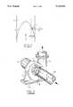
- FIG. 2Such a pump has been depicted in FIG. 2.
- This pumpincludes a housing 5, located on a base 6.
- a shift 7has been provided in the housing 5, onto which a vane 8 has been provided.
- the shaft 7is driven by an electric motor 9.
- a supply tube 10has been provided concentric with the shaft 7.
- a tangential drain pipe 11has been connected to the pump housing 5.
Landscapes
- Chemical & Material Sciences (AREA)
- Chemical Kinetics & Catalysis (AREA)
- Water Supply & Treatment (AREA)
- Hydrology & Water Resources (AREA)
- Engineering & Computer Science (AREA)
- Environmental & Geological Engineering (AREA)
- Life Sciences & Earth Sciences (AREA)
- Organic Chemistry (AREA)
- Analytical Chemistry (AREA)
- Separation Of Solids By Using Liquids Or Pneumatic Power (AREA)
- Centrifugal Separators (AREA)
- Solid-Sorbent Or Filter-Aiding Compositions (AREA)
- Physical Or Chemical Processes And Apparatus (AREA)
- Structures Of Non-Positive Displacement Pumps (AREA)
Abstract
Description
Claims (7)
Applications Claiming Priority (2)
| Application Number | Priority Date | Filing Date | Title |
|---|---|---|---|
| NL9000004ANL9000004A (en) | 1990-01-02 | 1990-01-02 | SEPARATION OF PARTICLES ADDRESSED ON CARRIER MATERIAL. |
| NL9000004 | 1990-01-02 |
Publications (1)
| Publication Number | Publication Date |
|---|---|
| US5110483Atrue US5110483A (en) | 1992-05-05 |
Family
ID=19856356
Family Applications (1)
| Application Number | Title | Priority Date | Filing Date |
|---|---|---|---|
| US07/628,643Expired - Fee RelatedUS5110483A (en) | 1990-01-02 | 1990-12-12 | Separation of particles adsorbed on carrier material |
Country Status (5)
| Country | Link |
|---|---|
| US (1) | US5110483A (en) |
| EP (1) | EP0439850B1 (en) |
| AT (1) | ATE126718T1 (en) |
| DE (1) | DE69021858T2 (en) |
| NL (1) | NL9000004A (en) |
Cited By (3)
| Publication number | Priority date | Publication date | Assignee | Title |
|---|---|---|---|---|
| US5849093A (en)* | 1992-01-08 | 1998-12-15 | Andrae; Juergen | Process for surface treatment with ions |
| US20090318238A1 (en)* | 2008-06-20 | 2009-12-24 | Rolls-Royce Plc | Multi-rotational crankshaft arrangement |
| CN104582232A (en)* | 2014-12-31 | 2015-04-29 | 江苏安德信超导加速器科技有限公司 | Rectangular particle beam scraper |
Citations (5)
| Publication number | Priority date | Publication date | Assignee | Title |
|---|---|---|---|---|
| US3926787A (en)* | 1973-03-02 | 1975-12-16 | C G Process Coal Company | Method and apparatus for reducing sulphur and ash content of coal |
| US4217207A (en)* | 1977-12-14 | 1980-08-12 | Liller Delbert I | Continuous method of cleaning a slurry of crushed raw coal |
| JPS5910317A (en)* | 1982-07-07 | 1984-01-19 | Daido Steel Co Ltd | Method of separating magnetic and non-magnetic components |
| JPS59154148A (en)* | 1983-02-22 | 1984-09-03 | Nec Corp | Separation of magnetic particles and nonmagnetic particles |
| US4531892A (en)* | 1983-03-14 | 1985-07-30 | Sunds Defibrator Aktiebolag | Apparatus for pumping of pulp |
Family Cites Families (1)
| Publication number | Priority date | Publication date | Assignee | Title |
|---|---|---|---|---|
| MC2175A1 (en)* | 1989-02-16 | 1992-05-22 | Golconda Eng & Mining | CLARIFICATION PROCESS |
- 1990
- 1990-01-02NLNL9000004Apatent/NL9000004A/ennot_activeApplication Discontinuation
- 1990-11-21DEDE69021858Tpatent/DE69021858T2/ennot_activeExpired - Fee Related
- 1990-11-21EPEP90203089Apatent/EP0439850B1/ennot_activeExpired - Lifetime
- 1990-11-21ATAT90203089Tpatent/ATE126718T1/ennot_activeIP Right Cessation
- 1990-12-12USUS07/628,643patent/US5110483A/ennot_activeExpired - Fee Related
Patent Citations (5)
| Publication number | Priority date | Publication date | Assignee | Title |
|---|---|---|---|---|
| US3926787A (en)* | 1973-03-02 | 1975-12-16 | C G Process Coal Company | Method and apparatus for reducing sulphur and ash content of coal |
| US4217207A (en)* | 1977-12-14 | 1980-08-12 | Liller Delbert I | Continuous method of cleaning a slurry of crushed raw coal |
| JPS5910317A (en)* | 1982-07-07 | 1984-01-19 | Daido Steel Co Ltd | Method of separating magnetic and non-magnetic components |
| JPS59154148A (en)* | 1983-02-22 | 1984-09-03 | Nec Corp | Separation of magnetic particles and nonmagnetic particles |
| US4531892A (en)* | 1983-03-14 | 1985-07-30 | Sunds Defibrator Aktiebolag | Apparatus for pumping of pulp |
Non-Patent Citations (2)
| Title |
|---|
| "Magnetic separation in water pollution control", IEEE Transactions on Magnetics vol. 11 No. 5 September 1975. |
| Magnetic separation in water pollution control , IEEE Transactions on Magnetics vol. 11 No. 5 September 1975.* |
Cited By (4)
| Publication number | Priority date | Publication date | Assignee | Title |
|---|---|---|---|---|
| US5849093A (en)* | 1992-01-08 | 1998-12-15 | Andrae; Juergen | Process for surface treatment with ions |
| US20090318238A1 (en)* | 2008-06-20 | 2009-12-24 | Rolls-Royce Plc | Multi-rotational crankshaft arrangement |
| US8052373B2 (en)* | 2008-06-20 | 2011-11-08 | Rolls-Royce Plc | Multi-rotational crankshaft arrangement |
| CN104582232A (en)* | 2014-12-31 | 2015-04-29 | 江苏安德信超导加速器科技有限公司 | Rectangular particle beam scraper |
Also Published As
| Publication number | Publication date |
|---|---|
| DE69021858D1 (en) | 1995-09-28 |
| EP0439850B1 (en) | 1995-08-23 |
| NL9000004A (en) | 1991-08-01 |
| ATE126718T1 (en) | 1995-09-15 |
| EP0439850A1 (en) | 1991-08-07 |
| DE69021858T2 (en) | 1996-01-11 |
Similar Documents
| Publication | Publication Date | Title |
|---|---|---|
| ZA872225B (en) | Methods for electrostatically charging up solid or liquid particles suspended in a gas stream by means of ions | |
| IE37455L (en) | Separating particles from a liquid | |
| US5110483A (en) | Separation of particles adsorbed on carrier material | |
| CA2203295A1 (en) | High efficiency method for isolating target substances using a multisample separation device | |
| JPS597508B2 (en) | magnetic separation device | |
| JPS5710311A (en) | Magnetic separator | |
| JPS6245363A (en) | Centrifugal concentrator | |
| SU1495100A1 (en) | Method of producing abrasive tool | |
| GB1494154A (en) | Magnetic separators | |
| US1527070A (en) | Magnetic centrifugal separator | |
| GB1025079A (en) | Method of and apparatus for a flocculating agent with a sludge being centrifuged | |
| JPH04326986A (en) | Separation of particle adsorbed on carrier material | |
| JPS5753257A (en) | Apparatus for separating magnetic particulate body | |
| JP3070091B2 (en) | Magnetic separation device | |
| RU2133155C1 (en) | Magneto-gravitational separator | |
| GB1369439A (en) | Centrifugal separator and method for separating particles from an aerosol | |
| JPS54131169A (en) | Hydroextractor | |
| JPS57111388A (en) | Production of emulsion fuel | |
| JPS55132684A (en) | Magnetic treatment of waste water | |
| US1727543A (en) | Magnetic separator | |
| ES2004550A6 (en) | Process and arrangement for the improvement of the dispersion of magnetic particles in a magnetic coating mass. | |
| SU1166826A1 (en) | Magnetic separator | |
| SU810280A1 (en) | Magnetic separator | |
| SU1639751A1 (en) | Magnetic separator | |
| SU566632A1 (en) | Hydrocyclone |
Legal Events
| Date | Code | Title | Description |
|---|---|---|---|
| AS | Assignment | Owner name:SMIT TRANSFORMATOREN B.V., GROENESTRAAT 336, NL-65 Free format text:ASSIGNMENT OF ASSIGNORS INTEREST.;ASSIGNOR:BOERSMA, RINTJE;REEL/FRAME:005558/0571 Effective date:19900910 | |
| AS | Assignment | Owner name:ENVIMAG B.V., NETHERLANDS Free format text:ASSIGNMENT OF ASSIGNORS INTEREST.;ASSIGNOR:SMIT TRANSFORMATOREN B.V.;REEL/FRAME:006274/0218 Effective date:19920828 | |
| FEPP | Fee payment procedure | Free format text:PAT HOLDER CLAIMS SMALL ENTITY STATUS - SMALL BUSINESS (ORIGINAL EVENT CODE: SM02); ENTITY STATUS OF PATENT OWNER: SMALL ENTITY | |
| REMI | Maintenance fee reminder mailed | ||
| AS | Assignment | Owner name:CARDAN, INC., PENNSYLVANIA Free format text:ASSIGNMENT OF ASSIGNORS INTEREST;ASSIGNOR:VAN RATINGEN, P.J.H.;REEL/FRAME:007854/0768 Effective date:19960131 | |
| FPAY | Fee payment | Year of fee payment:4 | |
| SULP | Surcharge for late payment | ||
| AS | Assignment | Owner name:CARDAN, INC., PENNSYLVANIA Free format text:REEL 7854 FRAMES 0768-0774 CORRECTED ASSIGNMENT;ASSIGNOR:VAN RATINGEN, P.J.H.;REEL/FRAME:008048/0480 Effective date:19960131 | |
| REMI | Maintenance fee reminder mailed | ||
| LAPS | Lapse for failure to pay maintenance fees | ||
| FP | Lapsed due to failure to pay maintenance fee | Effective date:20000505 | |
| STCH | Information on status: patent discontinuation | Free format text:PATENT EXPIRED DUE TO NONPAYMENT OF MAINTENANCE FEES UNDER 37 CFR 1.362 |