US5110163A - Pipe fitting with improved coupling body - Google Patents
Pipe fitting with improved coupling bodyDownload PDFInfo
- Publication number
- US5110163A US5110163AUS07/497,505US49750590AUS5110163AUS 5110163 AUS5110163 AUS 5110163AUS 49750590 AUS49750590 AUS 49750590AUS 5110163 AUS5110163 AUS 5110163A
- Authority
- US
- United States
- Prior art keywords
- tooth
- pipe
- tooth means
- groove
- sealing
- Prior art date
- Legal status (The legal status is an assumption and is not a legal conclusion. Google has not performed a legal analysis and makes no representation as to the accuracy of the status listed.)
- Expired - Lifetime
Links
- 230000008878couplingEffects0.000titleclaimsabstractdescription106
- 238000010168coupling processMethods0.000titleclaimsabstractdescription106
- 238000005859coupling reactionMethods0.000titleclaimsabstractdescription106
- 238000007789sealingMethods0.000claimsabstractdescription128
- 238000002955isolationMethods0.000claimsabstractdescription37
- 238000005452bendingMethods0.000claimsabstractdescription11
- 230000001788irregularEffects0.000claimsdescription9
- 239000000463materialSubstances0.000description21
- 229910001220stainless steelInorganic materials0.000description11
- 239000010935stainless steelSubstances0.000description11
- 229910000570CupronickelInorganic materials0.000description10
- YOCUPQPZWBBYIX-UHFFFAOYSA-Ncopper nickelChemical compound[Ni].[Cu]YOCUPQPZWBBYIX-UHFFFAOYSA-N0.000description10
- 235000001674Agaricus brunnescensNutrition0.000description2
- PXHVJJICTQNCMI-UHFFFAOYSA-NNickelChemical compound[Ni]PXHVJJICTQNCMI-UHFFFAOYSA-N0.000description2
- 230000006835compressionEffects0.000description2
- 238000007906compressionMethods0.000description2
- 239000012530fluidSubstances0.000description2
- 238000005304joiningMethods0.000description2
- 229910052751metalInorganic materials0.000description2
- 239000002184metalSubstances0.000description2
- 238000003466weldingMethods0.000description2
- RYGMFSIKBFXOCR-UHFFFAOYSA-NCopperChemical compound[Cu]RYGMFSIKBFXOCR-UHFFFAOYSA-N0.000description1
- 229910000831SteelInorganic materials0.000description1
- 229910052782aluminiumInorganic materials0.000description1
- XAGFODPZIPBFFR-UHFFFAOYSA-NaluminiumChemical compound[Al]XAGFODPZIPBFFR-UHFFFAOYSA-N0.000description1
- 239000002131composite materialSubstances0.000description1
- 230000001010compromised effectEffects0.000description1
- 229910052802copperInorganic materials0.000description1
- 239000010949copperSubstances0.000description1
- 238000004141dimensional analysisMethods0.000description1
- 230000003292diminished effectEffects0.000description1
- 210000002310elbow jointAnatomy0.000description1
- 239000000835fiberSubstances0.000description1
- 238000004519manufacturing processMethods0.000description1
- 238000000034methodMethods0.000description1
- 229910052759nickelInorganic materials0.000description1
- 229920000642polymerPolymers0.000description1
- 230000000717retained effectEffects0.000description1
- 102220168578rs199904091Human genes0.000description1
- 102220065847rs794726907Human genes0.000description1
- 238000010008shearingMethods0.000description1
- 125000006850spacer groupChemical group0.000description1
- 239000010959steelSubstances0.000description1
Images


Classifications
- F—MECHANICAL ENGINEERING; LIGHTING; HEATING; WEAPONS; BLASTING
- F16—ENGINEERING ELEMENTS AND UNITS; GENERAL MEASURES FOR PRODUCING AND MAINTAINING EFFECTIVE FUNCTIONING OF MACHINES OR INSTALLATIONS; THERMAL INSULATION IN GENERAL
- F16L—PIPES; JOINTS OR FITTINGS FOR PIPES; SUPPORTS FOR PIPES, CABLES OR PROTECTIVE TUBING; MEANS FOR THERMAL INSULATION IN GENERAL
- F16L13/00—Non-disconnectable pipe joints, e.g. soldered, adhesive, or caulked joints
- F16L13/14—Non-disconnectable pipe joints, e.g. soldered, adhesive, or caulked joints made by plastically deforming the material of the pipe, e.g. by flanging, rolling
- F16L13/146—Non-disconnectable pipe joints, e.g. soldered, adhesive, or caulked joints made by plastically deforming the material of the pipe, e.g. by flanging, rolling by an axially moveable sleeve
Definitions
- the present inventionis directed to a pipe fitting which allows pipes to be joined and sealed together with a mechanical fitting.
- the swage ringscan be mechanically urged over the outer surface of the coupling body from the first and second ends, respectively, of the coupling body.
- the two tubes to be joinedare inserted into the first and second ends of the coupling body, respectively.
- the inner surface of the coupling bodyincludes one or more teeth which are urged into engagement with the tubes in order to provide a mechanical seal.
- the outer surface of the coupling bodyincludes protrusions.
- the present inventionprovides for a pipe fitting with an advantageously improved coupling body. It is an object of the present invention to provide for a pipe fitting which has enhanced tensile strength making it more difficult for the pipes or tubes to be pulled out of the fitting along an axial direction.
- Such an arrangementis particularly advantageous for a thin walled pipe as the grooves with such dimensions will not push the pipe away from the teeth so as not to reduce the sealing effectiveness of the teeth. Further, such an arrangement is resistant to failure due to rooking or bending of the pipe about the fulcrum created by the engagement of the main sealing tooth with the pipe.
- Still another object of the present inventionis to provide the sealing teeth extending from the parent teeth with knife edges so that sealing teeth can bite into the outer surface of the pipe and at the same time mushroom and smash themselves against the outer surface of the pipe to fill cracks, crevices and any other surface imperfections on the outside of the pipe.
- the parent toothbeing substantially larger than the sealing teeth, provides the necessary tensile shear strength once the sealing teeth have been smashed against the outside of the pipe.
- the parent toothalso provides high compression strengths to deform thick wall pipes.
- Such an arrangementis particularly advantageous on a thin wall pipe as such a tooth arrangement provides thin, sharp sealing teeth for biting into the pipe and a larger parent tooth for withstanding tensile loading as opposed to a single tooth which could have a tendency, with respect to thin walled pipes, to deform the pipe without biting into the surface.
- the same tooth arrangementwould be advantageous for a thick walled pipe as the several sealing teeth would bite into the outer surface of the pipe with the parent tooth supporting the necessary tensile loading.
- an apparatusfor making pipe and tube connections which comprises a coupling body with an inner surface adapted for receiving a pipe or tube and an outer surface.
- a swage ringis provided which can be urged onto the outer surface in order to cause at least part of the inner surface to engage the pipe to create a seal.
- the inner surface of the coupling bodydescribes a first main seal tooth for making a substantial bite into the pipe as the swage ring is urged over the outer surface.
- the inner surfacefurther describes a second isolation tooth for making at least a minimal bite, and preferably a bite less than or equal to the bite of the first main seal tooth, into the pipe as the swage ring is urged over the outer surface.
- a grooveis defined between the first main seal tooth and second isolation tooth with the groove having a length between the first main seal tooth and second isolation tooth means and a depth.
- the length and depth of the groovesare selected so that the portion of the pipe located between the first main seal tooth and second isolation tooth is substantially retained in its initial shape after the swage ring has caused the first and second tooth to bite into the pipe.
- Such an arrangementincreases the tensile strength of the arrangement as the original outer diameter of the pipe must be overcome in order to have the pipe actually pull out of the coupling.
- the coupling bodyis designed not to deform the pipe in the area of the grooves, the pipe is not pushed away from the first main seal tooth and thus the effectiveness of the first main seal tooth in biting into the pipe is not diminished.
- the second isolation toothbeing spaced from the first tooth resists the rocking or flexing of the pipe about a fulcrum which is established by the first main seal tooth preventing failure of the main seal tooth and resultant leakage.
- the inner surfacedescribes a third inboard tooth for making at least a minimal bite into the pipe as the swage ring is urged over the outer surface.
- the third inboard toothis located on the opposite side of the first main seal tooth from the second isolation tooth.
- the third inboard toothassists in protecting the seal created by the first main seal tooth from rocking or flexing of the pipe about the first main seal tooth.
- a groove defined between the first main seal tooth and third inboard toothallows a portion of the pipe located adjacent said groove to retain an original shape in order to enhance the tensile strength of the connection.
- the first main seal toothdescribes a twin tooth arrangement wherein two sealing teeth extend from a parent tooth, which arrangement allows the twin teeth to be smashed against the pipe in order to provide an improved seal against any irregular outer surface on the pipe while providing for enhanced tensile strength due to the substantially larger profile of the parent tooth.
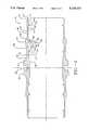
- FIG. 1depicts a plan view of an embodiment of the invention.
- FIG. 2depicts a partial cross-sectional view of a coupling body of an embodiment of the invention of FIG. 1 prior to the swage ring being urged over the coupling body.
- FIG. 3depicts a partial cross-sectional view of the embodiment of FIG. 1 with the tooth arrangement deformed against a pipe.
- FIG. 4depicts another coupling body of an embodiment of the invention having a twin tooth arrangement prior to a swage ring being urged over the coupling body.
- FIG. 5depicts an enlargement of the twin tooth arrangement of FIG. 4.
- FIG. 6depicts an enlargement of a twin tooth arrangement deformed against a pipe.
- FIGS. 7A and 7Bdepict a schematical representation of portions of the coupling body of the invention.
- Pipe fitting 20includes, in this particular embodiment, first and second swage rings 22, 24 which are urged over a coupling body 26 in order to secure together in a hermetically sealed manner first and second pipes 28, 30.
- first and second swage rings 22, 24which are urged over a coupling body 26 in order to secure together in a hermetically sealed manner first and second pipes 28, 30.
- the pipe fittings of the inventioncan be used equally well with pipes, tubes and/or other conduits and that such pipes, tubes and/or other conduits shall be collectively referred to as pipes herein.
- the coupling bodycan be constructed of any malleable metal such as aluminum, steel, copper and the like whereas the swage rings are generally constructed of a metal of equal or higher strength. Further, the coupling body and swage rings can also be comprised of, by way of example only, plastic materials, polymers and composite materials having various fibers and filaments therein.
- the coupling body 26 of FIG. 2is shown in a cross-sectional view taken through a diameter of the coupling body 26 prior to the swage rings 22, 24 being urged over the ends such as ends 32, 34, respectively.
- the swage rings 22, 24cause deformation of the coupling body 26, such that the coupling body 26 bites into and secures the two pipes 28, 30 together. It can be seen that not only is the coupling body 26 symmetrical about cylindrical axis 36 but it is similarly symmetrical about radial axis 38. Thus, the following discussion concerning the portion of the coupling body 26 which lies above the cylindrical axis 36 and to the right of the radial axis 38, applies equally to all other similarly shaped portions of the coupling body.
- the coupling body 26has an outer surface 40 and an inner surface 42.
- the outer surface 40includes an initial outboard facing incline cylindrical surface 44 which facilitates the initial engagement of the swage ring 24 over the end 34 of the coupling body 26.
- the coupling bodydefines a substantially flat cylindrical surface 46.
- a substantial cylindrical ramp 48is defined followed by a flat cylindrical surface or sealing rib 47 and a substantial inboard facing incline cylindrical surface which in the above identified patent and hereafter is referred to as reverse taper 50.
- reverse taper 50Following the reverse taper 50, there is a short flat cylindrical surface 51 to facilitate manufacturing, and a further outboard facing incline cylindrical surface 52.
- cylindrical stop flange 54which stops the progress of the swage ring 24 as it is urged over the coupling body 26. It is noted that a similar cylindrical stop flange 56 stops the movement of the other swage ring 22 over the coupling body 26.
- the cylindrical stop flanges 54, 56are separated by a cylindrical spacer flat 58.
- the inner surface 42 of the coupling body 26has in a preferred embodiment a plurality of teeth including main sealing tooth 60, an outboard isolation tooth 62 and an inboard tooth 64.
- the main sealing tooth 60 and the outboard isolation tooth 62define therebetween a first groove 66.
- the main sealing tooth 60 and the inboard tooth 64define therebetween a second groove 68.
- a pipe receiving groove 70is defined outboard of the outboard isolation tooth 62 with an additional groove 72 defined inboard of the inboard tooth 64.
- the first and second grooves 66, 68define groove bottom surfaces 67, 69, respectively.
- the lands 74, 76 and 78 of the teeth 60, 62, and 64, respectively, along with the internal cylindrical surface 80 which is located adjacent the stop flange 54define a cylinder which is approximately the outer diameter of the pipe to be inserted into the coupling body 26.
- the main sealing tooth 60is located adjacent to the sealing rib 47.
- the second tooth 62is located adjacent the flat cylindrical surface 46 with the inboard tooth 64 located adjacent the lower portion of the reverse taper 50.
- the reverse taper 50assists in driving the main sealing tooth 60 into the pipe in order to secure the pipe within the coupling body 26.
- reverse taper 50can be replaced by another type of protrusion, such as, for example, an elevated land, in order to perform the function of assisting in driving the main sealing tooth into the pipe.
- the design of the coupling body 26is such that when the swage ring 24 is urged over the coupling body the main sealing tooth 60 is urged into substantial biting and sealing engagement with the outer surface of the pipe 30. This sealing is caused as the swage ring 24 is urged passed the reverse taper 50.
- the isolation tooth 62is designed to make at least a minimal bite into the outer surface of the pipe 30, while the inboard tooth 64 is additionally designed to make at least a minimal bite into the outer surface of the pipe 30.
- the inboard tooth 64bites into the pipe an amount less than the isolation tooth 62 with the isolation tooth 62 biting into the pipe an amount equal to or less than the amount that the main sealing tooth 60 bites into the pipe.
- the purpose of the main sealing tooth 60is to substantially engage the surface of the pipe in order to provide a hermetical seal so that no fluid flowing through the pipe can be released between the tooth and the pipe.
- the tooth 60bites into the outer surface of the pipe, and simultaneously is somewhat smashed so as to fill any of the rough or irregular outside surface imperfections which are commonly found on the outside of the pipe.
- the tooth 60is sufficiently wide and has a sufficient profile such that it resists tensile loading along the axis of the pipe which could occur should there be a force on the pipe which might tend to pull it out of the coupling body. Such tensile loading can, in part, be created by high burst pressures as would be loaded onto the coupling by the fluid inside the pipe.
- the first and second grooves 66, 68 located on opposite side of the main sealing tooth 60are designed with a length and a depth such as that the portion of the pipe located adjacent such grooves is not substantially deformed as the swage ring is urged over the coupling body. If the pipe is in fact deformed, the grooves 66, 68 are of sufficient length and depth so that pipes can spring back to substantially their original shape after the swage ring has been fully seated over the coupling body.
- Such an arrangementis advantageous as it increases the tensile strength of the fitting due to the fact that the entire original diameter of the pipe must be overcome, as it interferes with the entire length of the tooth, before the pipe can be forced out of the coupling body due to tensile loading resulting from burst pressure or other forces.
- the portions of the pipe on either side of the main sealing tooth 60are not substantially deformed by the coupling body, the portion of the pipe adjacent the main sealing tooth is not substantially deformed and simultaneously urged away from the main sealing tooth 60 at the very time when the swage ring 24 is compressing the reverse taper 50 in order to urge the main sealing tooth 60 toward the pipe.
- the present designallows the main sealing tooth 60 to be used to maximum advantage to provide a seal without the coupling body itself forcing the pipe away from the tooth 60.
- the outboard isolation tooth 62 as well as the inboard tooth 64prevent the pivoting or rocking of the pipe about a fulcrum established where the main sealing tooth 60 bites into the pipe. Accordingly, the pipe is prevented from bending or flexing about the main sealing tooth 60, thus preventing relative motion between main sealing tooth 60 and the pipe and thus leakage at the point where the main sealing tooth engages the pipe 30. Such relative motion between main sealing tooth 60 and the pipe can cause the tooth 60 to plastically deform and wear resulting in the seal being compromised with resultant leakage. It is to be understood that for purposes of preventing such bending or rocking, that the outboard isolation tooth 62 is of most importance and that the inboard tooth 64 can in some embodiments, for purposes of economy, be dispensed with.
- Such a designhas a particular advantage with respect to thin walled pipes as the pipe is not collapsed away from the main sealing tooth 60 due to the contacting of the pipe caused by the first and second grooves on either side of the main sealing tooth and thus the main sealing tooth can more substantially bite into the thin walled pipe. Further, the arrangement increases the tensile loading which can be placed on the pipe fitting, as again the pipe on the sides of the main sealing tooth maintains its substantial original diameter and thus maintains substantial interference between the original outside diameter of the pipe and the depth of the main sealing tooth 60.
- FIG. 3demonstrates a cross-sectional view taken from the portion of FIG. 2 which has been previously described showing the swage ring 24 in place over the coupling body 26 with the main sealing tooth 60, the outboard isolation tooth 62, and the inboard tooth 64 engaging the pipe 30.
- FIGS. 4, 5 and 6An alternate embodiment of the main sealing tooth 60 is depicted in FIGS. 4, 5 and 6.
- the main sealing tooth 60is replaced with a twin tooth 90.
- the twin tooth 90includes a parent tooth 92 and extending therefrom a first sealing tooth 94 and a second sealing tooth 96.
- a groove 98is defined between the first sealing tooth 94 and the second sealing tooth 96.
- the width of the parent tooth 92is larger than the width of the main sealing tooth 60 of the prior embodiment while the width of the first sealing tooth 98 and the width of the second sealing tooth are smaller than the width of the main sealing tooth 60.
- the first sealing tooth 94 and the second sealing tooth 96have knife-edges.
- the two sealing teeth 94, 96bite into the outside surface of the pipe and at the same time mushroom and smash themselves to fill up crevices, cracks and other surface imperfections on the outside of the pipe.
- the wide parent tooth 92provides tensile shear strength once the two sealing teeth 94, 96 have been smashed and also provides high compressive strength to deform the outer surface of a thick walled pipe.
- the twin tooth designalso provides for good hermetic sealing for thin walled pipes as the sealing teeth 94, 96 bite into the thin walled pipe without the parent tooth simply deforming the pipe and this design can also withstand the tensile shearing loads required of teeth used with thick walled pipes. It is to be understood that an alternative embodiment of the invention can have only one sealing tooth mounted on the parent tooth.
- FIG. 6shows a cross-sectional view of the twin tooth 90 after a swage ring has been urged over the coupling body urging the twin tooth into sealing engagement with the pipe.
- FIG. 7Adepicts a portion of the coupling body of FIG. 2 and identifies the dimensions which are described by the below formula.
- the length of the body Arelates to the amount of bending that the coupling body can resist.
- Ashould not be too short otherwise there may be failure due to flexing.
- Such flexingcauses relative motion to occur between the main sealing tooth and the pipe resulting in leakage.
- the below specified grooves between the various teethwould not be able to fit within the coupling body.
- the theoretical pipe deformation at the sealing tooth 60is an empirically derived number based on the amount of deformation desired given the type of pipe and the tensile loading involved.
- the formulaindicates that the length of the main seal tooth is proportionate to the amount of deformation desired.
- the formulawill call for a longer main seal tooth and thus a larger groove depth D.
- the theoretical pipe deformation at the isolation tooth 62is derived in much the same manner as the theoretical pipe deformation for the main seal tooth is derived for the above equation with respect to the groove depth of the main seal tooth.
- the theoretical deformation at the isolation tooth 62can be, for example, 0% to 5%.
- the theoretical pipe deformation at the inboard tooth 64would then be less than 3% and in a preferred embodiment is between 0% and 3%.
- the groove width between the main seal tooth 60 and the isolation tooth 62is described by the formula:
- the distance from the end of the coupling body to the beginning of the main sealing toothis defined by the letter B in FIG. 7A and described for all materials as follows:
- the distance from the end of the coupling body to the beginning of the main sealing toothis defined by the letter B in FIG. 7A and described for stainless steel and copier nickel as follows:
- the land between the grooves which is the flat area of each of the teeth as shown in FIG. 7A,is as follows:
- Rthe outside diameter of the coupling body at the beginning of the reverse taper
- Mthe angle of the reverse taper.
- Rthe outside diameter of the coupling body at the beginning of the reverse taper
- Mthe angle of the reverse taper.
- the rationale for the distance to the start of the inboard toothis to have an inboard tooth just touching and supporting the pipe outside diameter at a minimum tolerance condition. At minimum tolerance there is no biting of the inboard tooth into the pipe.
- the outside diameter of the coupling body at zero deformationis determined theoretically from a dimensional analysis or tolerance study assuming no biting of the tooth into the pipe at a minimum tolerance condition.
- the outside diameter of the critical sectionis indicated by the letter N and that the thickness at the critical section is calculated to be a minimum wall thickness capable of withstanding the desired burst pressure.
- the wall thickness at the critical sectionis important as it is theoretically the weakest point of the coupling body.
- the width of the parent tooth which is designated by the letter Iis for stainless steel and copper nickel as follows: ##EQU10##
- the widthis calculated based on the burst pressure required so that the tooth can withstand the tensile shear forces placed upon it.
- the parent toothis also designed to support the small sealing teeth under expected compression forces.
- the width of the small sealing teethis indicated by the letter J and is designated for all materials as follows:
- the width of the small sealing teethis indicated by the letter J and is designated for stainless steel and copper nickel as follows:
- the groove depth of the small sealing teeth designated by the letter Kis, for all materials, as follows:
- the groove depth of the small sealing teeth designated by the letter K, for stainless steel and copper nickel,is as follows:
- the groove ramp angle as shown in FIG. 7Bis defined by the formula:
- the groove ramp angle as shown in FIG. 7Bis equal to, in a preferred embodiment 60° for stainless steel and copper nickel. This angle was selected to afford good resistance to shear loading and to provide for appropriate biting of the sealing teeth, which extend from the parent tooth, into the pipe.
- the present inventionis designed to successfully bring together two pipe ends or tubes and meet burst pressure and shear loading required.
- the pipesare fit into opposite ends of the coupling body.
- the swage ringsare forced over the coupling body in order to compress the reverse taper and the coupling body, forcing the teeth to bite into the pipes creating the hermetic seal that is resistant to tensile loads and bending.
- An appropriate hydraulic tool for causing the swage rings to be driven over the coupling bodyis disclosed in U.S. Pat. No. 4,189,817, issued Feb. 26, 1980 and entitled "HYDRAULIC ASSEMBLY TOOL FOR TUBE FITTINGS" which is licensed to the assignee of this invention and which is incorporated herein by reference.
Landscapes
- Engineering & Computer Science (AREA)
- General Engineering & Computer Science (AREA)
- Mechanical Engineering (AREA)
- Quick-Acting Or Multi-Walled Pipe Joints (AREA)
- Non-Disconnectible Joints And Screw-Threaded Joints (AREA)
- Joints With Sleeves (AREA)
- Mechanical Operated Clutches (AREA)
- Mutual Connection Of Rods And Tubes (AREA)
Abstract
Description
A=K1+K2 (actual pipe outside diameter)
A=0.534 (10) exp.[0.265 (actual pipe outside diameter)]
A=0.314+0.77 (actual pipe outside diameter)
C=K7+K8 (actual pipe outside diameter)/T
C=0.006+0.024650 (actual pipe outside diameter)/T
B=K9(A)-K10
B=0.635(A)-0.129
J=C3 (width of the parent tooth)
J=0.15 (width of the parent tooth).
K=C4 (actual pipe outside diameter/T) exp. C5
K=0.003 (actual pipe outside diameter/T) exp. 0.251
Groove Ramp angle=C6°
Claims (35)
K7+K8 (actual pipe outside diameter/T)
(theoretical pipe deformation at second tooth means)/2+K5+K6 (actual pipe outside diameter/T)
K9 (length of coupling body over which the swage ring transverse)-K10
K1+K2 (actual pipe outside diameter)
C4 (actual pipe outside diameter/T) exp. C5
C3 (width of parent tooth),
Priority Applications (9)
| Application Number | Priority Date | Filing Date | Title |
|---|---|---|---|
| US07/497,505US5110163A (en) | 1990-03-22 | 1990-03-22 | Pipe fitting with improved coupling body |
| US07/573,345US5114191A (en) | 1990-03-22 | 1990-08-24 | Pipe fitting with coupling body and improved isolation tooth arrangement |
| CA002078553ACA2078553C (en) | 1990-03-22 | 1991-03-14 | Pipe fitting with improved coupling body |
| PCT/US1991/001728WO1991014895A1 (en) | 1990-03-22 | 1991-03-14 | Pipe fitting with improved coupling body |
| DE69128420TDE69128420T2 (en) | 1990-03-22 | 1991-03-14 | TUBE SOCKET WITH IMPROVED CLUTCH BODY |
| JP50723891AJP3382938B2 (en) | 1990-03-22 | 1991-03-14 | Pipe fitting with improved coupling |
| AU75527/91AAU655174B2 (en) | 1990-03-22 | 1991-03-14 | Pipe fitting with improved coupling body |
| AT91906654TATE161080T1 (en) | 1990-03-22 | 1991-03-14 | TUBE SOCKET WITH IMPROVED COUPLING BODY |
| EP91906654AEP0521064B1 (en) | 1990-03-22 | 1991-03-14 | Pipe fitting with improved coupling body |
Applications Claiming Priority (1)
| Application Number | Priority Date | Filing Date | Title |
|---|---|---|---|
| US07/497,505US5110163A (en) | 1990-03-22 | 1990-03-22 | Pipe fitting with improved coupling body |
Related Child Applications (1)
| Application Number | Title | Priority Date | Filing Date |
|---|---|---|---|
| US07/573,345Continuation-In-PartUS5114191A (en) | 1990-03-22 | 1990-08-24 | Pipe fitting with coupling body and improved isolation tooth arrangement |
Publications (1)
| Publication Number | Publication Date |
|---|---|
| US5110163Atrue US5110163A (en) | 1992-05-05 |
Family
ID=23977152
Family Applications (1)
| Application Number | Title | Priority Date | Filing Date |
|---|---|---|---|
| US07/497,505Expired - LifetimeUS5110163A (en) | 1990-03-22 | 1990-03-22 | Pipe fitting with improved coupling body |
Country Status (8)
| Country | Link |
|---|---|
| US (1) | US5110163A (en) |
| EP (1) | EP0521064B1 (en) |
| JP (1) | JP3382938B2 (en) |
| AT (1) | ATE161080T1 (en) |
| AU (1) | AU655174B2 (en) |
| CA (1) | CA2078553C (en) |
| DE (1) | DE69128420T2 (en) |
| WO (1) | WO1991014895A1 (en) |
Cited By (61)
| Publication number | Priority date | Publication date | Assignee | Title |
|---|---|---|---|---|
| US5303958A (en)* | 1991-10-31 | 1994-04-19 | The Deutsch Company | Axially swaged fitting with composite swaging ring |
| US5375890A (en)* | 1992-08-24 | 1994-12-27 | Andersen; John I. | Thermo lock-n-seal tube end for polyethylene pipe |
| US5452921A (en)* | 1991-10-31 | 1995-09-26 | The Deutsch Company | Axially swaged fitting |
| US5709418A (en)* | 1995-03-20 | 1998-01-20 | Lokring Corporation | Pipe fitting with coupling body and swage ring with kickdown device to prevent reduction in sealing tooth contact force |
| DE19856523C1 (en)* | 1998-12-08 | 2000-03-09 | Selck Gmbh & Co Kg | Pipe coupling device e.g. for pressure medium pipes, has pressure cuffs at opposite ends of rotationally symmetrical body with teeth engaging inserted pipe end |
| US6131964A (en)* | 1998-12-15 | 2000-10-17 | Westinghouse Air Brake Company | SAS fitting for tube and pipe connections |
| DE19958102C1 (en)* | 1999-12-02 | 2001-02-08 | Selck Gmbh & Co Kg | Pressure-sealed coupling for pipes has a coupling sleeve with inner teeth covered by a pressure ring and end press rings which force the teeth by inner projections against the pipe surface with min pressure |
| WO2001040696A1 (en) | 1999-12-02 | 2001-06-07 | Selck Gmbh & Co. Kg | Device for producing a pipe coupling |
| US6450553B1 (en) | 1999-11-05 | 2002-09-17 | Mechl Llc | Axial swage fitting for large bore pipes and tubes |
| US20050025601A1 (en)* | 2003-07-31 | 2005-02-03 | Poast Tom G. | Tubular metal fitting expandable in a wall opening and method of installation |
| EP1589271A1 (en) | 2004-04-22 | 2005-10-26 | Lokring Technology Corporation | Fitting having low volume crevice |
| US20060186666A1 (en)* | 2005-02-24 | 2006-08-24 | Lokring Technology Corporation | Fitting with sequential sealing action |
| US20060284415A1 (en)* | 2005-03-16 | 2006-12-21 | Mckay Albert A | Medical gas and vacuum system |
| US20060284423A1 (en)* | 2003-02-24 | 2006-12-21 | Yutaka Katsuno | Extracorporeal circulation tube connector |
| US20070108760A1 (en)* | 2005-10-11 | 2007-05-17 | Lokring Technology Corporation | Fitting with complementary fitting materials |
| US20070110541A1 (en)* | 2005-10-28 | 2007-05-17 | Fatigue Technology, Inc. | Radially displaceable bushing for retaining a member relative to a structural workpiece |
| US20070289351A1 (en)* | 2006-04-27 | 2007-12-20 | Fatigue Technology, Inc. | Wave relieving geometric features in structural members that are radially expandable into workpieces |
| US20080001404A1 (en)* | 2005-02-25 | 2008-01-03 | Spencer Nicholson | Coupling |
| US20080034831A1 (en)* | 2006-06-29 | 2008-02-14 | Fatigue Technology, Inc. | Self-aligning tools and a mandrel with retention sleeve |
| US20080250603A1 (en)* | 2000-06-26 | 2008-10-16 | Skinner William A | Double flanged bushings and installation methods |
| US20100000280A1 (en)* | 2008-03-07 | 2010-01-07 | Leonard Frederick Reid | Expandable member with wave inhibitor and methods of using the same |
| US20100018282A1 (en)* | 2005-12-28 | 2010-01-28 | Fatigue Technology, Inc. | Mandrel assembly and method of using the same |
| US20100236048A1 (en)* | 2006-04-27 | 2010-09-23 | Fatigue Technology, Inc. | Alignment device and methods of using the same |
| US20110163536A1 (en)* | 2010-01-04 | 2011-07-07 | Lokring Technology, Llc | Mechanically Attached Fitting for Use in a Sour Environment |
| US20110182692A1 (en)* | 2008-07-18 | 2011-07-28 | Fatigue Technology, Inc. | Nut plate assembly and methods of using the same |
| USD645547S1 (en) | 2007-11-19 | 2011-09-20 | Value Plastics, Inc. | Male quick connect fitting |
| USD649240S1 (en) | 2009-12-09 | 2011-11-22 | Value Plastics, Inc. | Male dual lumen bayonet connector |
| US8069699B2 (en) | 2006-08-28 | 2011-12-06 | Fatigue Technology, Inc. | Installation/processing systems and methods of using the same |
| USD650478S1 (en) | 2009-12-23 | 2011-12-13 | Value Plastics, Inc. | Female dual lumen connector |
| USD652510S1 (en) | 2011-02-11 | 2012-01-17 | Value Plastics, Inc. | Connector for fluid tubing |
| USD652511S1 (en) | 2011-02-11 | 2012-01-17 | Value Plastics, Inc. | Female body of connector for fluid tubing |
| US8113546B2 (en) | 2005-06-10 | 2012-02-14 | Value Plastics, Inc. | Latching female fluid tubing coupler |
| USD655393S1 (en) | 2009-06-23 | 2012-03-06 | Value Plastics, Inc. | Multi-port valve |
| USD663022S1 (en) | 2011-02-11 | 2012-07-03 | Nordson Corporation | Male body of connector for fluid tubing |
| US8235426B2 (en) | 2008-07-03 | 2012-08-07 | Nordson Corporation | Latch assembly for joining two conduits |
| US8312606B2 (en) | 2007-10-16 | 2012-11-20 | Fatigue Technology, Inc. | Expandable fastener assembly with deformed collar |
| US8397756B2 (en) | 2006-01-20 | 2013-03-19 | Nordson Corporation | Fluid conduit couplers with depressible latch mechanism |
| US20130270821A1 (en)* | 2012-04-12 | 2013-10-17 | Gottfried Haener | Coupling assembly that establishes a pipe connection through pressure clamping |
| US8568034B2 (en) | 2006-01-11 | 2013-10-29 | Fatigue Technology, Inc. | Bushing kits, bearings, and methods of installation |
| USD698440S1 (en) | 2011-07-29 | 2014-01-28 | Nordson Corporation | Connector for fluid tubing |
| US8636455B2 (en) | 2009-04-10 | 2014-01-28 | Fatigue Technoloy, Inc. | Installable assembly having an expandable outer member and a fastener with a mandrel |
| US8647035B2 (en) | 2009-12-16 | 2014-02-11 | Fatigue Technology, Inc. | Modular nut plate assemblies and methods of using the same |
| USD699841S1 (en) | 2011-07-29 | 2014-02-18 | Nordson Corporation | Female body of connector for fluid tubing |
| USD699840S1 (en) | 2011-07-29 | 2014-02-18 | Nordson Corporation | Male body of connector for fluid tubing |
| US8763229B2 (en) | 2011-06-03 | 2014-07-01 | Fatigue Technology, Inc. | Expandable crack inhibitor method |
| USD709612S1 (en) | 2011-12-23 | 2014-07-22 | Nordson Corporation | Female dual lumen connector |
| US8938886B2 (en) | 2012-01-30 | 2015-01-27 | Fatigue Technology, Inc. | Smart installation/processing systems, components, and methods of operating the same |
| US9046205B2 (en) | 2009-12-09 | 2015-06-02 | Nordson Corporation | Fluid connector latches with profile lead-ins |
| US9114449B2 (en) | 2011-06-15 | 2015-08-25 | Fatigue Technology, Inc. | Modular nut plates with closed nut assemblies |
| US9388929B2 (en) | 2009-12-09 | 2016-07-12 | Nordson Corporation | Male bayonet connector |
| US9464741B2 (en) | 2009-12-09 | 2016-10-11 | Nordson Corporation | Button latch with integrally molded cantilever springs |
| GB2539972A (en)* | 2015-07-24 | 2017-01-04 | Hydra-Ring Ltd | A connector |
| USD785790S1 (en) | 2009-12-09 | 2017-05-02 | General Electric Company | Male dual lumen bayonet connector |
| US10176416B1 (en) | 2017-06-28 | 2019-01-08 | Lenlok Holdings, Llc | Energy harvesting RFID circuit, energy harvesting RFID tag, and associated methods |
| USD838366S1 (en) | 2016-10-31 | 2019-01-15 | Nordson Corporation | Blood pressure connector |
| US10663093B2 (en) | 2015-09-24 | 2020-05-26 | Lenlock Holdings, Llc | Pipe fitting with sensor |
| US10711930B2 (en) | 2009-12-09 | 2020-07-14 | Nordson Corporation | Releasable connection assembly |
| US10850451B2 (en) | 2016-07-01 | 2020-12-01 | Lenlok Holdings, Llc | Fluid system and method of manufacture via friction welding |
| WO2021217008A1 (en) | 2020-04-23 | 2021-10-28 | Lenlok Holdings, Llc | Fluid system comprising duplex stainless steel |
| EP4227565A4 (en)* | 2020-10-12 | 2024-04-10 | Megajoint. Co., Ltd. | Pipe connection device |
| US12241569B2 (en) | 2020-04-03 | 2025-03-04 | Lenlok Holdings Llc | Installation apparatus for pipe fittings and method of verifying proper installation |
Families Citing this family (6)
| Publication number | Priority date | Publication date | Assignee | Title |
|---|---|---|---|---|
| DE10021306C2 (en)* | 2000-04-27 | 2002-02-28 | Mapress Gmbh & Co Kg | pipe coupling |
| GB0503954D0 (en)* | 2005-02-25 | 2005-04-06 | Parker Hannifin Ipde | Connector and method of connecting tubes, pipes and round sections |
| EP1717503A3 (en) | 2005-04-28 | 2008-01-16 | F. X. Bachmann AG | Press fitting for pipes |
| FR2899307B1 (en)* | 2006-03-29 | 2012-02-03 | Permaswage | WASTE CONNECTING ACCESSORY FOR PIPES |
| JP6358906B2 (en)* | 2013-09-12 | 2018-07-18 | 株式会社リケンCkjv | Pipe fitting |
| KR102137995B1 (en)* | 2018-06-29 | 2020-07-27 | 주식회사 메가조인트 | Pipe connection apparatus |
Citations (4)
| Publication number | Priority date | Publication date | Assignee | Title |
|---|---|---|---|---|
| US2816781A (en)* | 1953-10-12 | 1957-12-17 | George V Woodling | Deep thread re-usable hose coupling |
| US3498648A (en)* | 1968-08-22 | 1970-03-03 | Boeing Co | High temperature and pressure tube fitting |
| US4061367A (en)* | 1974-08-26 | 1977-12-06 | Moebius Kurt Otto | Lockring tube joint |
| US4482174A (en)* | 1980-09-15 | 1984-11-13 | Lokring | Apparatus and method for making a tube connection |
- 1990
- 1990-03-22USUS07/497,505patent/US5110163A/ennot_activeExpired - Lifetime
- 1991
- 1991-03-14WOPCT/US1991/001728patent/WO1991014895A1/enactiveIP Right Grant
- 1991-03-14AUAU75527/91Apatent/AU655174B2/ennot_activeExpired
- 1991-03-14ATAT91906654Tpatent/ATE161080T1/enactive
- 1991-03-14CACA002078553Apatent/CA2078553C/ennot_activeExpired - Lifetime
- 1991-03-14EPEP91906654Apatent/EP0521064B1/ennot_activeExpired - Lifetime
- 1991-03-14DEDE69128420Tpatent/DE69128420T2/ennot_activeExpired - Lifetime
- 1991-03-14JPJP50723891Apatent/JP3382938B2/ennot_activeExpired - Lifetime
Patent Citations (4)
| Publication number | Priority date | Publication date | Assignee | Title |
|---|---|---|---|---|
| US2816781A (en)* | 1953-10-12 | 1957-12-17 | George V Woodling | Deep thread re-usable hose coupling |
| US3498648A (en)* | 1968-08-22 | 1970-03-03 | Boeing Co | High temperature and pressure tube fitting |
| US4061367A (en)* | 1974-08-26 | 1977-12-06 | Moebius Kurt Otto | Lockring tube joint |
| US4482174A (en)* | 1980-09-15 | 1984-11-13 | Lokring | Apparatus and method for making a tube connection |
Cited By (104)
| Publication number | Priority date | Publication date | Assignee | Title |
|---|---|---|---|---|
| US5452921A (en)* | 1991-10-31 | 1995-09-26 | The Deutsch Company | Axially swaged fitting |
| US5303958A (en)* | 1991-10-31 | 1994-04-19 | The Deutsch Company | Axially swaged fitting with composite swaging ring |
| US5375890A (en)* | 1992-08-24 | 1994-12-27 | Andersen; John I. | Thermo lock-n-seal tube end for polyethylene pipe |
| US5709418A (en)* | 1995-03-20 | 1998-01-20 | Lokring Corporation | Pipe fitting with coupling body and swage ring with kickdown device to prevent reduction in sealing tooth contact force |
| DE19856523C1 (en)* | 1998-12-08 | 2000-03-09 | Selck Gmbh & Co Kg | Pipe coupling device e.g. for pressure medium pipes, has pressure cuffs at opposite ends of rotationally symmetrical body with teeth engaging inserted pipe end |
| WO2000034706A1 (en) | 1998-12-08 | 2000-06-15 | Selck Gmbh & Co. Kg | Device for producing a pipe coupling |
| US6131964A (en)* | 1998-12-15 | 2000-10-17 | Westinghouse Air Brake Company | SAS fitting for tube and pipe connections |
| US6450553B1 (en) | 1999-11-05 | 2002-09-17 | Mechl Llc | Axial swage fitting for large bore pipes and tubes |
| AU777857B2 (en)* | 1999-12-02 | 2004-11-04 | Benteler Distribution International Gmbh | Device for producing a pipe coupling |
| WO2001040696A1 (en) | 1999-12-02 | 2001-06-07 | Selck Gmbh & Co. Kg | Device for producing a pipe coupling |
| DE19958102C1 (en)* | 1999-12-02 | 2001-02-08 | Selck Gmbh & Co Kg | Pressure-sealed coupling for pipes has a coupling sleeve with inner teeth covered by a pressure ring and end press rings which force the teeth by inner projections against the pipe surface with min pressure |
| US8128308B2 (en) | 2000-06-26 | 2012-03-06 | Fatigue Technology Inc. | Double flanged bushings and installation methods |
| US20080250603A1 (en)* | 2000-06-26 | 2008-10-16 | Skinner William A | Double flanged bushings and installation methods |
| US20060284423A1 (en)* | 2003-02-24 | 2006-12-21 | Yutaka Katsuno | Extracorporeal circulation tube connector |
| US20050025601A1 (en)* | 2003-07-31 | 2005-02-03 | Poast Tom G. | Tubular metal fitting expandable in a wall opening and method of installation |
| US7946628B2 (en) | 2003-07-31 | 2011-05-24 | Fatigue Technology, Inc. | Tubular metal fitting expandable in a wall opening and method of installation |
| US7448652B2 (en)* | 2003-07-31 | 2008-11-11 | Fatigue Technology Inc. | Tubular metal fitting expandable in a wall opening and method of installation |
| EP1589271B1 (en)* | 2004-04-22 | 2015-03-04 | Lokring Technology, LLC | Fitting having low volume crevice |
| EP1589271A1 (en) | 2004-04-22 | 2005-10-26 | Lokring Technology Corporation | Fitting having low volume crevice |
| US20050264006A1 (en)* | 2004-04-22 | 2005-12-01 | Mckay Albert A | Fitting having low volume crevice |
| US7503595B2 (en) | 2004-04-22 | 2009-03-17 | Lokring Technology, Llc | Fitting having low volume crevice |
| US20060186666A1 (en)* | 2005-02-24 | 2006-08-24 | Lokring Technology Corporation | Fitting with sequential sealing action |
| EP1851474A4 (en)* | 2005-02-24 | 2015-12-30 | Lokring Technology Llc | Improved fitting with sequential sealing acti |
| US7575257B2 (en) | 2005-02-24 | 2009-08-18 | Lokring Technology Corporation | Fitting with sequential sealing action |
| WO2006089396A1 (en) | 2005-02-24 | 2006-08-31 | Lokring Technology Llc | Improved fitting with sequential sealing acti |
| US20080001404A1 (en)* | 2005-02-25 | 2008-01-03 | Spencer Nicholson | Coupling |
| US9851034B2 (en) | 2005-02-25 | 2017-12-26 | Parker Hannifin Manufacturing Limited | Coupling |
| US20060284415A1 (en)* | 2005-03-16 | 2006-12-21 | Mckay Albert A | Medical gas and vacuum system |
| US8113546B2 (en) | 2005-06-10 | 2012-02-14 | Value Plastics, Inc. | Latching female fluid tubing coupler |
| US9194514B2 (en)* | 2005-10-11 | 2015-11-24 | Lokring Technology Corporation | Fitting with complementary fitting materials |
| KR101365539B1 (en)* | 2005-10-11 | 2014-02-20 | 록링 테크놀로지 엘엘씨 | Improved fitting with complementary fitting materials |
| US20070108760A1 (en)* | 2005-10-11 | 2007-05-17 | Lokring Technology Corporation | Fitting with complementary fitting materials |
| US20070110541A1 (en)* | 2005-10-28 | 2007-05-17 | Fatigue Technology, Inc. | Radially displaceable bushing for retaining a member relative to a structural workpiece |
| US20100018282A1 (en)* | 2005-12-28 | 2010-01-28 | Fatigue Technology, Inc. | Mandrel assembly and method of using the same |
| US8353193B2 (en) | 2005-12-28 | 2013-01-15 | Fatigue Technology, Inc. | Mandrel assembly and method of using the same |
| US7926319B2 (en) | 2005-12-28 | 2011-04-19 | Fatigue Technology, Inc. | Mandrel assembly and method of using the same |
| US8568034B2 (en) | 2006-01-11 | 2013-10-29 | Fatigue Technology, Inc. | Bushing kits, bearings, and methods of installation |
| US8397756B2 (en) | 2006-01-20 | 2013-03-19 | Nordson Corporation | Fluid conduit couplers with depressible latch mechanism |
| US8387436B2 (en) | 2006-04-27 | 2013-03-05 | Fatigue Technology, Inc. | Alignment device and methods of using the same |
| US8191395B2 (en) | 2006-04-27 | 2012-06-05 | Fatigue Technology, Inc. | Alignment device and methods of using the same |
| US20100236048A1 (en)* | 2006-04-27 | 2010-09-23 | Fatigue Technology, Inc. | Alignment device and methods of using the same |
| US20070289351A1 (en)* | 2006-04-27 | 2007-12-20 | Fatigue Technology, Inc. | Wave relieving geometric features in structural members that are radially expandable into workpieces |
| US7926318B2 (en) | 2006-04-27 | 2011-04-19 | Fatigue Technology, Inc. | Alignment device and methods of using the same |
| US8117885B2 (en) | 2006-06-29 | 2012-02-21 | Fatigue Technology, Inc. | Mandrel with retention sleeve and methods of using the same |
| US8061178B2 (en) | 2006-06-29 | 2011-11-22 | Fatigue Technology, Inc. | Self-aligning tools and seating assemblies |
| US7958766B2 (en) | 2006-06-29 | 2011-06-14 | Fatigue Technology, Inc. | Self-aligning tools and a mandrel with retention sleeve |
| US20080034831A1 (en)* | 2006-06-29 | 2008-02-14 | Fatigue Technology, Inc. | Self-aligning tools and a mandrel with retention sleeve |
| US20110214270A1 (en)* | 2006-06-29 | 2011-09-08 | Fatigue Technology, Inc. | Self-aligning tools and seating assemblies |
| US20110209518A1 (en)* | 2006-06-29 | 2011-09-01 | Fatigue Technology, Inc. | Mandrel with retention sleeve and methods of using the same |
| US8402806B2 (en) | 2006-08-28 | 2013-03-26 | Fatigue Technology, Inc. | Installation/processing systems and methods of using the same |
| US8069699B2 (en) | 2006-08-28 | 2011-12-06 | Fatigue Technology, Inc. | Installation/processing systems and methods of using the same |
| US8312606B2 (en) | 2007-10-16 | 2012-11-20 | Fatigue Technology, Inc. | Expandable fastener assembly with deformed collar |
| USD654573S1 (en) | 2007-11-19 | 2012-02-21 | Value Plastics, Inc. | Female quick connect fitting |
| USD645547S1 (en) | 2007-11-19 | 2011-09-20 | Value Plastics, Inc. | Male quick connect fitting |
| US10010983B2 (en) | 2008-03-07 | 2018-07-03 | Fatigue Technology, Inc. | Expandable member with wave inhibitor and methods of using the same |
| US20100000280A1 (en)* | 2008-03-07 | 2010-01-07 | Leonard Frederick Reid | Expandable member with wave inhibitor and methods of using the same |
| US8235426B2 (en) | 2008-07-03 | 2012-08-07 | Nordson Corporation | Latch assembly for joining two conduits |
| US8448994B2 (en) | 2008-07-03 | 2013-05-28 | Nordson Corporation | Latch assembly for joining two conduits |
| US8596688B2 (en) | 2008-07-03 | 2013-12-03 | Nordson Corporation | Latch assembly for joining two conduits |
| US20110182692A1 (en)* | 2008-07-18 | 2011-07-28 | Fatigue Technology, Inc. | Nut plate assembly and methods of using the same |
| US8506222B2 (en) | 2008-07-18 | 2013-08-13 | Fatigue Technology, Inc. | Nut plate assembly and methods of using the same |
| US8636455B2 (en) | 2009-04-10 | 2014-01-28 | Fatigue Technoloy, Inc. | Installable assembly having an expandable outer member and a fastener with a mandrel |
| USD655393S1 (en) | 2009-06-23 | 2012-03-06 | Value Plastics, Inc. | Multi-port valve |
| US9732891B2 (en) | 2009-12-09 | 2017-08-15 | General Electric Company | Male bayonet connector |
| US9046205B2 (en) | 2009-12-09 | 2015-06-02 | Nordson Corporation | Fluid connector latches with profile lead-ins |
| US10711930B2 (en) | 2009-12-09 | 2020-07-14 | Nordson Corporation | Releasable connection assembly |
| US10001236B2 (en) | 2009-12-09 | 2018-06-19 | General Electric Company | Male bayonet connector |
| USD785790S1 (en) | 2009-12-09 | 2017-05-02 | General Electric Company | Male dual lumen bayonet connector |
| US9464741B2 (en) | 2009-12-09 | 2016-10-11 | Nordson Corporation | Button latch with integrally molded cantilever springs |
| US9388929B2 (en) | 2009-12-09 | 2016-07-12 | Nordson Corporation | Male bayonet connector |
| USD649240S1 (en) | 2009-12-09 | 2011-11-22 | Value Plastics, Inc. | Male dual lumen bayonet connector |
| US8647035B2 (en) | 2009-12-16 | 2014-02-11 | Fatigue Technology, Inc. | Modular nut plate assemblies and methods of using the same |
| USD650478S1 (en) | 2009-12-23 | 2011-12-13 | Value Plastics, Inc. | Female dual lumen connector |
| CN102822586A (en)* | 2010-01-04 | 2012-12-12 | 洛克英技术公司 | Mechanically attached fitting for use in a sour environment |
| US20110163536A1 (en)* | 2010-01-04 | 2011-07-07 | Lokring Technology, Llc | Mechanically Attached Fitting for Use in a Sour Environment |
| US8870237B2 (en) | 2010-01-04 | 2014-10-28 | Lokring Technology, Llc | Mechanically attached fitting for use in a sour environment |
| USD652510S1 (en) | 2011-02-11 | 2012-01-17 | Value Plastics, Inc. | Connector for fluid tubing |
| USD652511S1 (en) | 2011-02-11 | 2012-01-17 | Value Plastics, Inc. | Female body of connector for fluid tubing |
| USD663022S1 (en) | 2011-02-11 | 2012-07-03 | Nordson Corporation | Male body of connector for fluid tubing |
| US8763229B2 (en) | 2011-06-03 | 2014-07-01 | Fatigue Technology, Inc. | Expandable crack inhibitor method |
| US9114449B2 (en) | 2011-06-15 | 2015-08-25 | Fatigue Technology, Inc. | Modular nut plates with closed nut assemblies |
| USD698440S1 (en) | 2011-07-29 | 2014-01-28 | Nordson Corporation | Connector for fluid tubing |
| USD712537S1 (en) | 2011-07-29 | 2014-09-02 | Nordson Corporation | Connector for fluid tubing |
| USD699840S1 (en) | 2011-07-29 | 2014-02-18 | Nordson Corporation | Male body of connector for fluid tubing |
| USD699841S1 (en) | 2011-07-29 | 2014-02-18 | Nordson Corporation | Female body of connector for fluid tubing |
| USD709612S1 (en) | 2011-12-23 | 2014-07-22 | Nordson Corporation | Female dual lumen connector |
| US8938886B2 (en) | 2012-01-30 | 2015-01-27 | Fatigue Technology, Inc. | Smart installation/processing systems, components, and methods of operating the same |
| US10130985B2 (en) | 2012-01-30 | 2018-11-20 | Fatigue Technology, Inc. | Smart installation/processing systems, components, and methods of operating the same |
| US10843250B2 (en) | 2012-01-30 | 2020-11-24 | Fatigue Technology, Inc. | Smart installation/processing systems, components, and methods of operating the same |
| US20130270821A1 (en)* | 2012-04-12 | 2013-10-17 | Gottfried Haener | Coupling assembly that establishes a pipe connection through pressure clamping |
| GB2539972A (en)* | 2015-07-24 | 2017-01-04 | Hydra-Ring Ltd | A connector |
| GB2539972B (en)* | 2015-07-24 | 2017-07-19 | Hydra-Ring Ltd | A connector |
| US10663093B2 (en) | 2015-09-24 | 2020-05-26 | Lenlock Holdings, Llc | Pipe fitting with sensor |
| US10850451B2 (en) | 2016-07-01 | 2020-12-01 | Lenlok Holdings, Llc | Fluid system and method of manufacture via friction welding |
| USD838366S1 (en) | 2016-10-31 | 2019-01-15 | Nordson Corporation | Blood pressure connector |
| USD961070S1 (en) | 2016-10-31 | 2022-08-16 | Nordson Corporation | Blood pressure connector |
| USD964557S1 (en) | 2016-10-31 | 2022-09-20 | Nordson Corporation | Blood pressure connector |
| USD964558S1 (en) | 2016-10-31 | 2022-09-20 | Nordson Corporation | Blood pressure connector |
| USD967955S1 (en) | 2016-10-31 | 2022-10-25 | Nordson Corporation | Blood pressure connector |
| US10657431B2 (en) | 2017-06-28 | 2020-05-19 | Lenlock Holdings, Llc | Energy harvesting RFID circuit, energy harvesting RFID tag, and associated methods |
| US10176416B1 (en) | 2017-06-28 | 2019-01-08 | Lenlok Holdings, Llc | Energy harvesting RFID circuit, energy harvesting RFID tag, and associated methods |
| US12241569B2 (en) | 2020-04-03 | 2025-03-04 | Lenlok Holdings Llc | Installation apparatus for pipe fittings and method of verifying proper installation |
| WO2021217008A1 (en) | 2020-04-23 | 2021-10-28 | Lenlok Holdings, Llc | Fluid system comprising duplex stainless steel |
| EP4227565A4 (en)* | 2020-10-12 | 2024-04-10 | Megajoint. Co., Ltd. | Pipe connection device |
Also Published As
| Publication number | Publication date |
|---|---|
| JPH05506083A (en) | 1993-09-02 |
| JP3382938B2 (en) | 2003-03-04 |
| ATE161080T1 (en) | 1997-12-15 |
| DE69128420T2 (en) | 1998-05-28 |
| AU655174B2 (en) | 1994-12-08 |
| EP0521064B1 (en) | 1997-12-10 |
| WO1991014895A1 (en) | 1991-10-03 |
| EP0521064A4 (en) | 1993-03-17 |
| CA2078553C (en) | 1999-11-02 |
| DE69128420D1 (en) | 1998-01-22 |
| AU7552791A (en) | 1991-10-21 |
| CA2078553A1 (en) | 1991-09-23 |
| EP0521064A1 (en) | 1993-01-07 |
Similar Documents
| Publication | Publication Date | Title |
|---|---|---|
| US5110163A (en) | Pipe fitting with improved coupling body | |
| US5114191A (en) | Pipe fitting with coupling body and improved isolation tooth arrangement | |
| US4328982A (en) | Fluid fitting | |
| US5484174A (en) | Pipe coupling and method of joining materials | |
| US5335946A (en) | Cooperating combination of a gland and a grip ring installed in restrained sealed bolted joints of fluid piping systems including both plastic pipe and metallic pipe | |
| US4880260A (en) | Method of joining pipes | |
| US6106029A (en) | Pipe coupling with improved pull-out restraint | |
| EP0480478B1 (en) | Tube coupling | |
| US5181752A (en) | Pipe fitting with swage ring locking mechanism | |
| EP0455490B1 (en) | Restrained pipe joint | |
| US5076617A (en) | Seal for aseptic fitting assembly | |
| EP2470817B1 (en) | Press-connect fitting with improved grab-ring function | |
| EP1589271B1 (en) | Fitting having low volume crevice | |
| US7490866B2 (en) | Anchoring device for pipe coupling | |
| EP0072199A1 (en) | Pipe coupling | |
| EP0122099A1 (en) | Connection of and sealing of tubular members | |
| HUE030217T2 (en) | Mechanically attached fitting for use in a sour environment | |
| NL8401879A (en) | POWER LINE CONNECTIONS. | |
| GB2032557A (en) | Fittings for fluid-tight connection to tubular members | |
| GB1591743A (en) | Pipe couplings | |
| US4725082A (en) | Coupling | |
| JP3117606B2 (en) | Pipe fittings | |
| JP2000081175A (en) | Pipe coupling | |
| GB2167146A (en) | Pipe coupling | |
| JP3541107B2 (en) | Connection structure of fluid transport pipe |
Legal Events
| Date | Code | Title | Description |
|---|---|---|---|
| AS | Assignment | Owner name:LOKRING CORPORATION, CALIFORNIA Free format text:ASSIGNMENT OF ASSIGNORS INTEREST.;ASSIGNORS:BENSON, ROBERT W.;DIETEMANN, CHRISTOPHER G.;BEILEY, MARK J.;AND OTHERS;REEL/FRAME:005344/0094 Effective date:19900515 | |
| STCF | Information on status: patent grant | Free format text:PATENTED CASE | |
| FEPP | Fee payment procedure | Free format text:PAT HLDR NO LONGER CLAIMS SMALL ENT STAT AS SMALL BUSINESS (ORIGINAL EVENT CODE: LSM2); ENTITY STATUS OF PATENT OWNER: LARGE ENTITY | |
| FPAY | Fee payment | Year of fee payment:4 | |
| AS | Assignment | Owner name:VENTURE BANKING GROUP, A DIVISION OF CUPERTINO NAT Free format text:SECURITY AGREEMENT;ASSIGNOR:LOKRING CORPORATION;REEL/FRAME:008920/0307 Effective date:19971125 | |
| AS | Assignment | Owner name:LOKRING CORPORATION, CALIFORNIA Free format text:RELEASE OF SECURITY INTEREST;ASSIGNOR:VENTURE BANKING GROUP, A DIVISION OF CUPERTINO NATIONAL BANK;REEL/FRAME:009375/0832 Effective date:19980730 | |
| FPAY | Fee payment | Year of fee payment:8 | |
| AS | Assignment | Owner name:WESTINGHOUSE AIR BRAKE TECHNOLOGIES CORPORATION, P Free format text:CHANGE OF NAME;ASSIGNOR:WESTINGHOUSE AIR BRAKE COMPANY;REEL/FRAME:010628/0840 Effective date:19991223 | |
| AS | Assignment | Owner name:WESTINGHOUSE AIR BRAKE COMPANY, PENNSYLVANIA Free format text:ASSIGNMENT OF ASSIGNORS INTEREST;ASSIGNOR:LOKRING CORPORATION;REEL/FRAME:011177/0427 Effective date:19980728 | |
| FPAY | Fee payment | Year of fee payment:12 | |
| AS | Assignment | Owner name:2010185 ONTARIO, INC., OHIO Free format text:ASSIGNMENT OF ASSIGNORS INTEREST;ASSIGNOR:WESTINGHOUSE AIR BRAKE TECHNOLOGIES CORPORATION;REEL/FRAME:014953/0191 Effective date:20020328 | |
| AS | Assignment | Owner name:LOKRING TECHNOLOGY CORPORATION, CANADA Free format text:CHANGE OF NAME;ASSIGNOR:2010185 ONTARIO, INC.;REEL/FRAME:014953/0661 Effective date:20020328 | |
| AS | Assignment | Owner name:LOKRING TECHNOLOGY, LLC,OHIO Free format text:ASSIGNMENT OF ASSIGNORS INTEREST;ASSIGNOR:LOKRING TECHNOLOGY CORPORATION;REEL/FRAME:019000/0869 Effective date:20070221 Owner name:LOKRING TECHNOLOGY, LLC, OHIO Free format text:ASSIGNMENT OF ASSIGNORS INTEREST;ASSIGNOR:LOKRING TECHNOLOGY CORPORATION;REEL/FRAME:019000/0869 Effective date:20070221 |