US5109623A - Loading device for muzzle-loading firearms - Google Patents
Loading device for muzzle-loading firearmsDownload PDFInfo
- Publication number
- US5109623A US5109623AUS07/648,570US64857091AUS5109623AUS 5109623 AUS5109623 AUS 5109623AUS 64857091 AUS64857091 AUS 64857091AUS 5109623 AUS5109623 AUS 5109623A
- Authority
- US
- United States
- Prior art keywords
- chamber
- projectile
- opening
- charge
- muzzle
- Prior art date
- Legal status (The legal status is an assumption and is not a legal conclusion. Google has not performed a legal analysis and makes no representation as to the accuracy of the status listed.)
- Expired - Fee Related
Links
- 239000000843powderSubstances0.000claimsabstractdescription10
- 238000009527percussionMethods0.000claimsdescription8
- 239000000463materialSubstances0.000claimsdescription2
- 230000037452primingEffects0.000claims1
- 238000007789sealingMethods0.000claims1
- MFOUDYKPLGXPGO-UHFFFAOYSA-NpropachlorChemical compoundClCC(=O)N(C(C)C)C1=CC=CC=C1MFOUDYKPLGXPGO-UHFFFAOYSA-N0.000description6
- 238000000034methodMethods0.000description5
- 239000007858starting materialSubstances0.000description5
- 239000003721gunpowderSubstances0.000description4
- 210000002445nippleAnatomy0.000description4
- 239000011324beadSubstances0.000description2
- 238000010276constructionMethods0.000description2
- 210000005224forefingerAnatomy0.000description2
- 238000010304firingMethods0.000description1
- 239000012815thermoplastic materialSubstances0.000description1
Images

Classifications
- F—MECHANICAL ENGINEERING; LIGHTING; HEATING; WEAPONS; BLASTING
- F41—WEAPONS
- F41C—SMALLARMS, e.g. PISTOLS, RIFLES; ACCESSORIES THEREFOR
- F41C9/00—Other smallarms, e.g. hidden smallarms or smallarms specially adapted for underwater use
- F41C9/08—Muzzle-loading smallarms; Smallarms with flintlock mechanisms; Accessories therefor
- F41C9/085—Accessories for loading muzzle loading guns, e.g. magazines or tools for loading
Definitions
- the present inventionrelates to a loading device for a muzzle-loading firearm.
- the loading of a muzzle-loading firearmis a slow and cumbersome process which involves several components such as gunpowder, a projectile, a patch, and a percussion cap.
- This processhas been simplified substantially by the development of loading devices which conveniently carry the charge components for the firearm and which aid in the loading process itself.
- One particular loading deviceincludes a body which has a chamber that is open at both ends. A projectile is held in the lower part of the chamber and functions as a closure member for that end of the chamber and gunpowder is held in the upper part of the chamber. The opening which is adjacent the gunpowder is closed by a closure member.
- a muzzle-loading rifleis loaded with the aid of the prior art loading device by first pouring the powder charge which is contained in the chamber of the body into the muzzle of the rifle barrel. The lower section of the body is then placed against the muzzle of the rifle barrel and a projectile is pushed from the chamber into the barrel of the rifle with a ramrod.
- the loading device and the end of the riflemust both be held in proper alignment with one hand while the ramrod is manipulated with the other hand. This is an extremely difficult procedure with the use of a conventional ramrod so that in most cases a so-called "short starter" is used for the purpose of transferring the projectile from the loading device into the barrel of the rifle.
- a principle object of the inventionto provide a loading device for a muzzle loader which contains one or more charge components, including a projectile, and which is effective to transfer the projectile from the loading device and into the muzzle of a rifle barrel without using the ramrod or a "short starter".
- Another object of this inventionis the provision of a loading device for a muzzle-loading firearm which contains all of the charge components for firing a muzzle-loading firearm.
- a further object of the present inventionis the provision of a loading device for a muzzle-loading firearm which is simple in construction, easy to carry, and easy to use.
- the inventionconsists of a charge container for use of a muzzle-loading firearm.
- the charge containerincludes a first body which has an elongated projectile chamber which is open at both ends.
- a second bodyhas a charge chamber which is open at one end for holding a charge of gunpowder.
- the second bodyhas an elongated plunger which is slidably mounted in the projectile chamber for pushing the projectile out of the projectile chamber and into the muzzle opening of a firearm.
- the opening to the charge chamberis closed by a cap. More specifically, the cap also contains a primer which fits into an additional cavity in the second body when the opening to the powder chamber is closed by the cover.
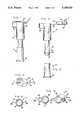
- FIG. 1is a front elevational view of a loading device, embodying the principles of the present invention and showing the closure in the closed condition,
- FIG. 2is a top plan view thereof
- FIG. 3is a front elevational view of the portion of the loading device for containing a powder charge and shown with the closure in the open position,
- FIG. 4is a top plan view thereof
- FIG. 5is a front elevational view of the portion of the loading device for containing the projectile
- FIG. 6is a top plan view thereof
- FIG. 7is a vertical cross-sectional view of the projectile holding portion of the loading device taken along the line VII--VII of FIG. 6, and looking in the direction of the arrows,
- FIG. 8is a vertical cross-sectional view of the powder holding portion of the loading device taken along the line VIII--VIII of FIG. 4, and looking in the direction of the arrows and
- FIG. 9is a vertical cross-sectional view of the assembled and loaded loading device taken along the line IX--IX of FIG. 2 and looking in the direction of the arrows.
- the loading device of the present inventionis generally indicated by the reference numeral 10 and comprises a first body which is generally indicated by the reference numeral 12 and a second body which is generally indicated by the reference numeral 14.
- the first body 12is tube shaped and has a cylindrical projectile chamber 16 which is open at both ends, an inlet opening 18 at one end and an outlet opening 20 at the opposite end.
- the wall of the projectile chamber 16has an annular groove 22 for a purpose to be described.
- An outwardly extending annular flange 24is located near the outlet opening 20.
- the second body 14has a cylindrical charge chamber 26 which has a single opening 28 at the top of the chamber.
- An elongated plunger 30is located beneath the chamber 26 and has a flat bottom end surface 32 and a cylindrical outer surface 33.
- An annular bead 34extends from the cylindrical surface 33 at a point which is spaced from the end surface 32 as shown in FIGS. 2 and 4.
- the upper end of the body 14has a protrusion 36 which contains a cavity 38 that is separated from the cavity 26.
- a closure member, generally indicated by the reference numeral 40is connected to the body 14 by a flexible and resilient web 42.
- the web 42 as well as the entire loading deviceare preferably made of thermoplastic material.
- the closure member 40comprises an annular wall 44 and a percussion cap holder 46 which includes a cavity 48 and a longitudinal slot 49.
- the annular wall 44closes the opening 28 and the cap holder 46 closes the opening 39 to the cavity 38.
- the loading device 10is utilized by placing a projectile 50 in the lower end of the chamber 16 and inserting the plunger 30 into the chamber 16 so that the bead 34 snaps into the annular groove 22. This positions the bottom end surface 32 just above the forward end of the projectile 50 as shown in FIG. 9.
- the chamber 26is filled with a powder charge 52 and a percussion cap is placed within the cavity 48 of the cap holder 46.
- the closure member 40is folded about the web 42 to close the openings 28 and 39 as shown in FIG. 9.
- the loading device 10is now ready to be used for loading a muzzle-loading firearm.
- the muzzle-loading firearmis loaded by opening the closure member 40 and emptying the powder charge 52 into the barrel of the firearm.
- the projectile 50is then loaded into the firearm by placing the flange 24 against the muzzle of the firearm so that the opening 20 is aligned with the muzzle opening.
- the body 14is pushed toward the muzzle of the firearm, thereby causing the plunger 30 to push the projectile 50 out of the chamber 16 and into the bore of the firearm.
- a ramrodis then used for pushing the projectile to its final loading position into the barrel of the firearm.
- the percussion capis attached to the breech nipple by holding the device in the hand with the forefinger on the backside of the cap socket 48.
- the capis pushed onto the nipple with the forefinger and the device is pulled away, leaving the percussion cap on the breech nipple.
- This slot 49allows the cap holder 46 to deflect around the percussion cap when the percussion cap is placed on the breech nipple of the firearm.
Landscapes
- Engineering & Computer Science (AREA)
- General Engineering & Computer Science (AREA)
- Portable Nailing Machines And Staplers (AREA)
Abstract
Description
Claims (3)
Priority Applications (1)
| Application Number | Priority Date | Filing Date | Title |
|---|---|---|---|
| US07/648,570US5109623A (en) | 1991-01-31 | 1991-01-31 | Loading device for muzzle-loading firearms |
Applications Claiming Priority (1)
| Application Number | Priority Date | Filing Date | Title |
|---|---|---|---|
| US07/648,570US5109623A (en) | 1991-01-31 | 1991-01-31 | Loading device for muzzle-loading firearms |
Publications (1)
| Publication Number | Publication Date |
|---|---|
| US5109623Atrue US5109623A (en) | 1992-05-05 |
Family
ID=24601339
Family Applications (1)
| Application Number | Title | Priority Date | Filing Date |
|---|---|---|---|
| US07/648,570Expired - Fee RelatedUS5109623A (en) | 1991-01-31 | 1991-01-31 | Loading device for muzzle-loading firearms |
Country Status (1)
| Country | Link |
|---|---|
| US (1) | US5109623A (en) |
Cited By (16)
| Publication number | Priority date | Publication date | Assignee | Title |
|---|---|---|---|---|
| US5806227A (en)* | 1997-02-28 | 1998-09-15 | Yoder; David Duane | Percussion cap device |
| US6185853B1 (en) | 1999-04-26 | 2001-02-13 | Fn Manufacturing Co Inc | Speedloader for shotgun |
| US6637143B1 (en)* | 2002-02-28 | 2003-10-28 | Richard Shawn Wykle | Quick loading muzzleloader system |
| US20040103574A1 (en)* | 2002-09-04 | 2004-06-03 | Williams Dean N. | Multiple auto primer system for muzzle-loading firearm |
| US20050115129A1 (en)* | 2002-09-04 | 2005-06-02 | Lizarralde Inigo I. | Multiple auto primer system for muzzle-loading firearm |
| US20060162218A1 (en)* | 2005-01-25 | 2006-07-27 | Church Douglas W | Muzzle loader |
| USD565689S1 (en) | 2007-07-10 | 2008-04-01 | Downin Paul D | Firearm loading tool |
| US7451563B1 (en)* | 2006-03-24 | 2008-11-18 | Mcknight Larry Donald | 8-in-1 deluxe field loader |
| US8112932B1 (en)* | 2009-03-23 | 2012-02-14 | Vollmer Mickey S | Tool for single handed reloading of muzzle loading firearms |
| US8151506B2 (en) | 2008-09-04 | 2012-04-10 | Michael Anders | Muzzle loader unloading tool |
| US9228793B2 (en) | 2010-06-15 | 2016-01-05 | Gregory Samaras | All-in-one muzzle loading device |
| US9500437B2 (en) | 2014-11-26 | 2016-11-22 | Michael J. Grazioplene | Muzzle loading system |
| US9752847B2 (en) | 2015-03-20 | 2017-09-05 | Foster Steele | Speed loader for black powder arms and related methods |
| US11143485B2 (en)* | 2017-08-07 | 2021-10-12 | Martin T. Garthaffner | Loading device and method |
| US20240175657A1 (en)* | 2022-11-23 | 2024-05-30 | Cedar Mountain Products, LLC | Apparatus for storing and dispensing propellant, a bullet, and a primer for a muzzleloader |
| US12352530B2 (en) | 2023-01-04 | 2025-07-08 | Michael J. Grazioplene | Muzzle loading system |
Citations (8)
| Publication number | Priority date | Publication date | Assignee | Title |
|---|---|---|---|---|
| US4050175A (en)* | 1976-09-10 | 1977-09-27 | Mulinix Lavern F | Loading devices for muzzle loading rifles |
| US4112606A (en)* | 1977-05-12 | 1978-09-12 | William Griffin | Muzzle loading device |
| US4373285A (en)* | 1980-09-29 | 1983-02-15 | Grout Kenneth M | Gun muzzle loader |
| US4466209A (en)* | 1983-03-11 | 1984-08-21 | Leon Strickland | Loader for muzzle-loading firearms |
| US4509284A (en)* | 1983-04-22 | 1985-04-09 | Naber James R | Shotgun speed loader |
| US4756110A (en)* | 1987-07-29 | 1988-07-12 | Beltron James M | Speed loader |
| US4862623A (en)* | 1988-09-06 | 1989-09-05 | Delap Jess E | Quick loading device for muzzle-loaded weapons |
| US5035183A (en)* | 1990-03-12 | 1991-07-30 | David Luxton | Frangible nonlethal projectile |
- 1991
- 1991-01-31USUS07/648,570patent/US5109623A/ennot_activeExpired - Fee Related
Patent Citations (8)
| Publication number | Priority date | Publication date | Assignee | Title |
|---|---|---|---|---|
| US4050175A (en)* | 1976-09-10 | 1977-09-27 | Mulinix Lavern F | Loading devices for muzzle loading rifles |
| US4112606A (en)* | 1977-05-12 | 1978-09-12 | William Griffin | Muzzle loading device |
| US4373285A (en)* | 1980-09-29 | 1983-02-15 | Grout Kenneth M | Gun muzzle loader |
| US4466209A (en)* | 1983-03-11 | 1984-08-21 | Leon Strickland | Loader for muzzle-loading firearms |
| US4509284A (en)* | 1983-04-22 | 1985-04-09 | Naber James R | Shotgun speed loader |
| US4756110A (en)* | 1987-07-29 | 1988-07-12 | Beltron James M | Speed loader |
| US4862623A (en)* | 1988-09-06 | 1989-09-05 | Delap Jess E | Quick loading device for muzzle-loaded weapons |
| US5035183A (en)* | 1990-03-12 | 1991-07-30 | David Luxton | Frangible nonlethal projectile |
Cited By (19)
| Publication number | Priority date | Publication date | Assignee | Title |
|---|---|---|---|---|
| US5806227A (en)* | 1997-02-28 | 1998-09-15 | Yoder; David Duane | Percussion cap device |
| US6185853B1 (en) | 1999-04-26 | 2001-02-13 | Fn Manufacturing Co Inc | Speedloader for shotgun |
| US6637143B1 (en)* | 2002-02-28 | 2003-10-28 | Richard Shawn Wykle | Quick loading muzzleloader system |
| US20040103574A1 (en)* | 2002-09-04 | 2004-06-03 | Williams Dean N. | Multiple auto primer system for muzzle-loading firearm |
| US6865838B2 (en) | 2002-09-04 | 2005-03-15 | Dean N. Williams | Multiple auto primer system for muzzle-loading firearm |
| US20050115129A1 (en)* | 2002-09-04 | 2005-06-02 | Lizarralde Inigo I. | Multiple auto primer system for muzzle-loading firearm |
| US20060162218A1 (en)* | 2005-01-25 | 2006-07-27 | Church Douglas W | Muzzle loader |
| US7165351B2 (en)* | 2005-01-25 | 2007-01-23 | Church Douglas W | Muzzle loader |
| US7451563B1 (en)* | 2006-03-24 | 2008-11-18 | Mcknight Larry Donald | 8-in-1 deluxe field loader |
| USD565689S1 (en) | 2007-07-10 | 2008-04-01 | Downin Paul D | Firearm loading tool |
| US8151506B2 (en) | 2008-09-04 | 2012-04-10 | Michael Anders | Muzzle loader unloading tool |
| US8112932B1 (en)* | 2009-03-23 | 2012-02-14 | Vollmer Mickey S | Tool for single handed reloading of muzzle loading firearms |
| US9228793B2 (en) | 2010-06-15 | 2016-01-05 | Gregory Samaras | All-in-one muzzle loading device |
| US9500437B2 (en) | 2014-11-26 | 2016-11-22 | Michael J. Grazioplene | Muzzle loading system |
| US9752847B2 (en) | 2015-03-20 | 2017-09-05 | Foster Steele | Speed loader for black powder arms and related methods |
| US11143485B2 (en)* | 2017-08-07 | 2021-10-12 | Martin T. Garthaffner | Loading device and method |
| US20240175657A1 (en)* | 2022-11-23 | 2024-05-30 | Cedar Mountain Products, LLC | Apparatus for storing and dispensing propellant, a bullet, and a primer for a muzzleloader |
| US12339096B2 (en)* | 2022-11-23 | 2025-06-24 | Cedar Mountain Products, LLC | Apparatus for storing and dispensing propellant, a bullet, and a primer for a muzzleloader |
| US12352530B2 (en) | 2023-01-04 | 2025-07-08 | Michael J. Grazioplene | Muzzle loading system |
Similar Documents
| Publication | Publication Date | Title |
|---|---|---|
| US5109623A (en) | Loading device for muzzle-loading firearms | |
| US4112606A (en) | Muzzle loading device | |
| US4614052A (en) | Firearm magazine and magazine loader | |
| US4875303A (en) | Muzzleloading powder and projectile tool | |
| US4152858A (en) | Fast loader for muzzle-loader | |
| US4550517A (en) | Quick-loading device for muzzle-loading rifles | |
| US3153981A (en) | Receiver for spent shells | |
| US4466209A (en) | Loader for muzzle-loading firearms | |
| BE522888A (en) | ||
| US4411088A (en) | Water resistant charge container for firearms | |
| US4862623A (en) | Quick loading device for muzzle-loaded weapons | |
| US4135322A (en) | Muzzle charge storage and loading accessory for muzzle loading fire arms | |
| US4601125A (en) | Muzzle loading apparatus | |
| US5097615A (en) | Muzzle loading device for muzzle loading firearms | |
| US4229897A (en) | Muzzle loading apparatus | |
| US3956844A (en) | Loading device for a tubular projectile | |
| US10190836B2 (en) | Loader | |
| US4123868A (en) | Gunpowder charge and projectile container | |
| US4862621A (en) | Device for facilitating loading of a shotgun | |
| US4207698A (en) | Device for loading muzzle loading rifles and method of preparing the device | |
| FR2685468B1 (en) | SOCKET TUBE FOR RIFLE WITH RIFLE THAT CAN RETAIN BALL FRAGMENTS. | |
| US4419839A (en) | Charge container for firearms | |
| US3580172A (en) | Underwater projectile for firing a cartridge upon impact | |
| US4602449A (en) | Combination screw-in choke holder and plug device | |
| US4135321A (en) | Firing nipple |
Legal Events
| Date | Code | Title | Description |
|---|---|---|---|
| AS | Assignment | Owner name:K. W. THOMPSON TOOL COMPANY, INC.,, NEW HAMPSHIRE Free format text:ASSIGNMENT OF ASSIGNORS INTEREST.;ASSIGNOR:FRENCH, KENDRICK L.;REEL/FRAME:005592/0295 Effective date:19901113 | |
| AS | Assignment | Owner name:THOMPSON INTELLECTUAL PROPERTIES, LTD., NEW HAMPSH Free format text:ASSIGNMENT OF ASSIGNORS INTEREST;ASSIGNOR:K.W. THOMPSON TOOL COMPANY, INC.;REEL/FRAME:007062/0855 Effective date:19940712 | |
| FPAY | Fee payment | Year of fee payment:4 | |
| AS | Assignment | Owner name:USTRUST, MASSACHUSETTS Free format text:SECURITY INTEREST;ASSIGNOR:THOMPSON INTELLECTUAL PROPERTIES, LTD.;REEL/FRAME:009423/0066 Effective date:19980828 | |
| REMI | Maintenance fee reminder mailed | ||
| LAPS | Lapse for failure to pay maintenance fees | ||
| FP | Lapsed due to failure to pay maintenance fee | Effective date:20000505 | |
| AS | Assignment | Owner name:THOMPSON INTELLECTUAL PROPERTIES, LTD., NEW HAMPSH Free format text:RELEASE BY SECURED PARTY;ASSIGNOR:CITIZENS BANK OF MASSACHUSETTS;REEL/FRAME:018746/0127 Effective date:20070102 | |
| STCH | Information on status: patent discontinuation | Free format text:PATENT EXPIRED DUE TO NONPAYMENT OF MAINTENANCE FEES UNDER 37 CFR 1.362 |