US5109541A - Car-mounted type booster system for hand-held phone - Google Patents
Car-mounted type booster system for hand-held phoneDownload PDFInfo
- Publication number
- US5109541A US5109541AUS07/614,449US61444990AUS5109541AUS 5109541 AUS5109541 AUS 5109541AUS 61444990 AUS61444990 AUS 61444990AUS 5109541 AUS5109541 AUS 5109541A
- Authority
- US
- United States
- Prior art keywords
- duplexer
- amplifier
- signal
- power module
- output
- Prior art date
- Legal status (The legal status is an assumption and is not a legal conclusion. Google has not performed a legal analysis and makes no representation as to the accuracy of the status listed.)
- Expired - Lifetime
Links
Images


Classifications
- H—ELECTRICITY
- H04—ELECTRIC COMMUNICATION TECHNIQUE
- H04B—TRANSMISSION
- H04B1/00—Details of transmission systems, not covered by a single one of groups H04B3/00 - H04B13/00; Details of transmission systems not characterised by the medium used for transmission
- H04B1/38—Transceivers, i.e. devices in which transmitter and receiver form a structural unit and in which at least one part is used for functions of transmitting and receiving
- H04B1/3827—Portable transceivers
- H04B1/3877—Arrangements for enabling portable transceivers to be used in a fixed position, e.g. cradles or boosters
- H—ELECTRICITY
- H04—ELECTRIC COMMUNICATION TECHNIQUE
- H04B—TRANSMISSION
- H04B1/00—Details of transmission systems, not covered by a single one of groups H04B3/00 - H04B13/00; Details of transmission systems not characterised by the medium used for transmission
- H04B1/38—Transceivers, i.e. devices in which transmitter and receiver form a structural unit and in which at least one part is used for functions of transmitting and receiving
- H04B1/40—Circuits
- H04B1/50—Circuits using different frequencies for the two directions of communication
- H04B1/52—Hybrid arrangements, i.e. arrangements for transition from single-path two-direction transmission to single-direction transmission on each of two paths or vice versa
Definitions
- This inventionrelates to a car-mounted type booster system for hand-held phone.
- hand-held phoneshad low antenna gain for limited carrying space, had relatively strong body effect while receiving and transmitting, and also had low output power for limited battery power.
- the present invention of a car-mounted type booster systemachieves said object.
- the present inventionincludes (1) a power control loop using the compared data between a RF output from the hand-held phone, converted into digital code by an A/D converter, and a reference value, and (2) adding a low-noise amplifier for compensating losses due to such connections as the connections of duplexers.
- the power control loopcan be comprised as transistor array circuits without using the A/D converter.
- FIG. 1is a block diagram for a preferred embodiment of the present invention
- FIG. 2is a circuit diagram of an A/D converter
- FIG. 3is a circuit diagram of a D/A converter
- FIG. 4is a block diagram for another preferred embodiment of the present invention.
- FIG. 5is a circuit diagram of a power control part.
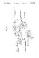
- FIG. 1is a block diagram for the preferred embodiment of the present invention.
- the booster systemincludes a first duplexer 10, a second duplexer 12, a low-noise amplifier 11, a first coupler 13, a second coupler 18, a first amplifier 14, a second amplifier 19, and a Power Module 16. Also included are an A/D converter 15, and a D/A converter 17.
- the signal from the hand-held phone HHPis applied to the coupler 13 through the duplexer 10 at first, and distributed into two lines. One of them is connected to the D/A converter 17 through the first amplifier 14 and the A/D converter 15. And the other is connected to the second duplexer 12 through the Power Module 16 and the coupler 18.
- the output of the second duplexer 12is connected to the first duplexer 10 through the low-noise amplifier 11. And, the output of the second coupler 18 is connected to the D/A converter 17, which controls the Power Module 16, through the second amplifier 19.
- Full-duplex RF signalis separated into transmission band (Tx) and reception band (Rx).
- Txtransmission band
- Rxreception band
- the signal, received by the hand-held phone,is applied to the Power Module 16 through the first coupler 13.
- the first coupler 13regulates the output of the duplexer 10 for a constant value.
- the Power Module 16amplifies the output power signal from the first coupler 13.
- FIG. 2is a circuit diagram of an A/D converter.
- the A/D converter 15is used for the detection of the received output level from the hand-held phone.
- the signal, amplified by the first amplifier 14,is applied to logarithmic scale bar graph IC's 23 and 24 through a first comparator 21 and a second comparator 22.
- the digital code for a specific voltage section segmented by the logarithmic scale bar graph IC'sis applied to an encoder 29 through switching diodes 27 and 28. The segmentation described above is usually called window comparating.
- the encoder 29sends to D/A converter 17 a 3-bit signal generated along the 8-bit signal from the logarithmic scale bar graph IC's 23 and 24.
- FIG. 3is a circuit diagram of a D/A converter.
- the Tx ON signal from the A/D converterfor determining whether the signal from the hand-held phone is a transmission signal Tx or not, is applied to the D/A converter through a resistor 62 and a transistor 61.
- the signal from the transistor 61 which controls a transistor 60the power supply to the Power Module 16 is switched on or off.
- the 3-bit digital transmission output datais applied to an analog switch 63 of the D/A converter 17 as control signal.
- the voltage prepared by a potentiometer 64is applied to a (+) terminal after passing through the 8-step analog switch 63.
- the result valueis fed to a transistor 56 through a diode 65.
- the transistor 56alternates between on and off.
- a transistor 52is off, because there is no current applied to the base terminal of the transistor 52, and vice versa.
- the output of the transistor 52is applied to a control terminal of the Power Module.
- part numbers 51, 53, 54, 57, 58, and 59are resistors, and 49 and 55 are condensers.
- the signal from the first coupler 13amplified enough to the same output power level as that of car phone, is radiated through the antenna of the duplexer 12.
- FIG. 4is a block diagram of another preferred embodiment of the present invention.
- the booster systemincludes a first duplexer 61, a second duplexer 62, a first coupler 63, a second coupler 64, a Power Module 65, a Power Control Part 66, a low-noise amplifier 68, a first amplifier 69, and a second amplifier 70.
- the full-duplex RF signalis divided into the transmission band (Tx) and the reception band (Rx) by the first duplexer 61. And the reception sensitivity is improved by adding a low-noise amplifier 68 for compensation of loss due to the dependent connection between the first duplexer 61 and the second duplexer 62. Since the signal transmitted from the hand-held phone, is applied to the Power Module 65 through the first coupler 63, the first coupler 63 regulates the output of the first duplexer 61 to a constant level, and the Power Module 65 amplifies the power of the signal from the first coupler 63.
- the Power Control Part 66receives the signal from the first coupler 63 through the first amplifier 69 and the signal from the second coupler 64 through the second amplifier 70.
- the first amplifier 69outputs the amplified output of compared value between a reference voltage and an output voltage of the first coupler 63
- the second amplifier 70outputs the amplified output of compared value between a reference voltage and an output voltage of the second coupler 64.
- FIG. 5is a circuit diagram of a Power Control Part and first and second amplifiers.
- the first amplifierincludes resistors 71 and 74, potentiometer 73, and a differential amplifier 71
- the second amplifierincludes resistors 95, 79, 80, and 77, a condenser 76, and a differential amplifier 75.
- the comparatorcomprising a resistor 85, a condenser 86, and an differential amplifier 84, applies the result value to a transistor 93 through a diode 87.
- the output voltage of the first amplifier 69is defined as reference voltage for the comparator. Therefore, the operation of the Power Control Part having a feedback loop depends on the detection output of the first coupler 63.
- the comparatorcomprising a potentiometer 82 and an amplifier 81 applies the compared value between the output voltage of the first amplifier 69 and the reference voltage specified by the potentiometer 82 to a transistor 88.
- the transistor 88turns off, then it cannot drive a transistor 92.
- the transistor 88turns on, then it drives the transistor 92.
- the outputis applied to the Power Module 65, then it controls the power supply to the Power Module 65.
- the hand-held phone signal through the first coupler 63is amplified enough to the level desired and radiated by means of antenna through the second duplexer 62.
- the reference numbers 83,89,90,91, and 95show resistors, respectively.
- the present inventionmakes a hand-held phone which equals a car phone in performance possible, and has a great flexibility and more improved RF characteristics. Especially, it has good reception sensitivity and image rejection performance against the 2nd harmonic spurious signal and the 3rd harmonic spurious signal. In addition, it also has extremely good band limit effect because of the dependent connection of the duplexers.
Landscapes
- Engineering & Computer Science (AREA)
- Computer Networks & Wireless Communication (AREA)
- Signal Processing (AREA)
- Transmitters (AREA)
- Amplifiers (AREA)
- Mobile Radio Communication Systems (AREA)
- Transceivers (AREA)
Abstract
Description
Claims (3)
Applications Claiming Priority (4)
| Application Number | Priority Date | Filing Date | Title |
|---|---|---|---|
| KR1019890017457AKR910008129B1 (en) | 1989-11-29 | 1989-11-29 | Car mount type booster system of hand held phone |
| KR1989-17457 | 1989-11-29 | ||
| KR1989-17456 | 1989-11-29 | ||
| KR1019890017456AKR910010064B1 (en) | 1989-11-29 | 1989-11-29 | Car mount type booster system of hand held phone |
Publications (1)
| Publication Number | Publication Date |
|---|---|
| US5109541Atrue US5109541A (en) | 1992-04-28 |
Family
ID=26628131
Family Applications (1)
| Application Number | Title | Priority Date | Filing Date |
|---|---|---|---|
| US07/614,449Expired - LifetimeUS5109541A (en) | 1989-11-29 | 1990-11-16 | Car-mounted type booster system for hand-held phone |
Country Status (3)
| Country | Link |
|---|---|
| US (1) | US5109541A (en) |
| JP (1) | JP2559532B2 (en) |
| SE (1) | SE510683C3 (en) |
Cited By (13)
| Publication number | Priority date | Publication date | Assignee | Title |
|---|---|---|---|---|
| US5276917A (en)* | 1991-10-22 | 1994-01-04 | Nokia Mobile Phones Ltd. | Transmitter switch-on in a dual-mode mobile phone |
| US5446782A (en)* | 1991-07-16 | 1995-08-29 | Kabushiki Kaisha Toshiba | Terminal connecting device having an auto data receiving function |
| US5568537A (en)* | 1993-03-15 | 1996-10-22 | Shechet; Mark J. | Transportable mobile cellular system |
| US5995813A (en)* | 1993-02-05 | 1999-11-30 | Kabushiki Kaisha Toshiba | Radio telephone and independently controlled booster |
| US6029072A (en)* | 1996-01-25 | 2000-02-22 | Oki Telecom, Inc. | Portable telephone with terminal mode facility |
| US6205344B1 (en)* | 1994-05-06 | 2001-03-20 | Motorola, Inc. | Power adapter with integral radio frequency port |
| US6230031B1 (en) | 1997-03-31 | 2001-05-08 | Oki Telecom, Inc. | Power amplifying circuitry for wireless radio transceivers |
| US6389303B1 (en)* | 1998-01-30 | 2002-05-14 | Nec Corporation | Booster for amplifying the transmission output of a handy phone |
| US6459915B2 (en) | 1997-09-02 | 2002-10-01 | Matsushita Electric Industrial Co. Ltd. | External adapter for a portable cellular phone |
| US20030100351A1 (en)* | 2001-11-27 | 2003-05-29 | Arrista Technologies, Inc. | Booster amplifier for cellular telephone cradles |
| US6728520B2 (en)* | 1999-08-31 | 2004-04-27 | Qualcomm Incorporated | System and method for constant loop gain in a closed loop circuit |
| US20050086873A1 (en)* | 2003-10-24 | 2005-04-28 | Manuel Mares | Slopped roof flashing system and method of use |
| US10485057B2 (en) | 2017-04-11 | 2019-11-19 | Wilson Electronics, Llc | Signal booster with coaxial cable connections |
Citations (6)
| Publication number | Priority date | Publication date | Assignee | Title |
|---|---|---|---|---|
| US4625240A (en)* | 1984-07-25 | 1986-11-25 | Eeco, Inc. | Adaptive automatic gain control |
| US4723304A (en)* | 1986-02-27 | 1988-02-02 | Nec Corporation | Mobile station and a mobile radio communication network in which electric power is saved without reduction of an activity ratio of radio communication channels |
| US4870698A (en)* | 1986-10-29 | 1989-09-26 | Oki Electric Industry Co., Ltd. | Output power control circuit for a mobile radio apparatus |
| US4903325A (en)* | 1987-06-30 | 1990-02-20 | Mitsubishi Denki Kabushiki Kaisha | Portable wireless communication apparatus |
| US4962543A (en)* | 1987-09-29 | 1990-10-09 | Kabushiki Kaisha Toshiba | Battery rundown protection system for an automobile having a radio telephone apparatus with an automatic answering function |
| US4997611A (en)* | 1987-08-22 | 1991-03-05 | Carl Freudenberg | Process for the production of nonwoven webs including a drawing step and a separate blowing step |
Family Cites Families (2)
| Publication number | Priority date | Publication date | Assignee | Title |
|---|---|---|---|---|
| JPS6189727A (en)* | 1984-10-09 | 1986-05-07 | Nec Corp | Radio equipment |
| JPH0728231B2 (en)* | 1989-04-10 | 1995-03-29 | 三菱電機株式会社 | Booster device and radio connected to the booster device |
- 1990
- 1990-11-16USUS07/614,449patent/US5109541A/ennot_activeExpired - Lifetime
- 1990-11-19SESE9003684Apatent/SE510683C3/ennot_activeIP Right Cessation
- 1990-11-26JPJP2318168Apatent/JP2559532B2/ennot_activeExpired - Lifetime
Patent Citations (6)
| Publication number | Priority date | Publication date | Assignee | Title |
|---|---|---|---|---|
| US4625240A (en)* | 1984-07-25 | 1986-11-25 | Eeco, Inc. | Adaptive automatic gain control |
| US4723304A (en)* | 1986-02-27 | 1988-02-02 | Nec Corporation | Mobile station and a mobile radio communication network in which electric power is saved without reduction of an activity ratio of radio communication channels |
| US4870698A (en)* | 1986-10-29 | 1989-09-26 | Oki Electric Industry Co., Ltd. | Output power control circuit for a mobile radio apparatus |
| US4903325A (en)* | 1987-06-30 | 1990-02-20 | Mitsubishi Denki Kabushiki Kaisha | Portable wireless communication apparatus |
| US4997611A (en)* | 1987-08-22 | 1991-03-05 | Carl Freudenberg | Process for the production of nonwoven webs including a drawing step and a separate blowing step |
| US4962543A (en)* | 1987-09-29 | 1990-10-09 | Kabushiki Kaisha Toshiba | Battery rundown protection system for an automobile having a radio telephone apparatus with an automatic answering function |
Cited By (18)
| Publication number | Priority date | Publication date | Assignee | Title |
|---|---|---|---|---|
| US5446782A (en)* | 1991-07-16 | 1995-08-29 | Kabushiki Kaisha Toshiba | Terminal connecting device having an auto data receiving function |
| US5276917A (en)* | 1991-10-22 | 1994-01-04 | Nokia Mobile Phones Ltd. | Transmitter switch-on in a dual-mode mobile phone |
| US5995813A (en)* | 1993-02-05 | 1999-11-30 | Kabushiki Kaisha Toshiba | Radio telephone and independently controlled booster |
| US5568537A (en)* | 1993-03-15 | 1996-10-22 | Shechet; Mark J. | Transportable mobile cellular system |
| US6205344B1 (en)* | 1994-05-06 | 2001-03-20 | Motorola, Inc. | Power adapter with integral radio frequency port |
| US6212415B1 (en) | 1994-05-06 | 2001-04-03 | Motorola, Inc. | Power adapter with integral radio frequency port |
| US6029072A (en)* | 1996-01-25 | 2000-02-22 | Oki Telecom, Inc. | Portable telephone with terminal mode facility |
| US6230031B1 (en) | 1997-03-31 | 2001-05-08 | Oki Telecom, Inc. | Power amplifying circuitry for wireless radio transceivers |
| US6459915B2 (en) | 1997-09-02 | 2002-10-01 | Matsushita Electric Industrial Co. Ltd. | External adapter for a portable cellular phone |
| US6389303B1 (en)* | 1998-01-30 | 2002-05-14 | Nec Corporation | Booster for amplifying the transmission output of a handy phone |
| US6577850B2 (en) | 1998-01-30 | 2003-06-10 | Nec Corporation | Booster for amplifying the transmission output of a handy phone |
| US6728520B2 (en)* | 1999-08-31 | 2004-04-27 | Qualcomm Incorporated | System and method for constant loop gain in a closed loop circuit |
| US20030100351A1 (en)* | 2001-11-27 | 2003-05-29 | Arrista Technologies, Inc. | Booster amplifier for cellular telephone cradles |
| US6892080B2 (en)* | 2001-11-27 | 2005-05-10 | Arrista Technologies, Inc. | Booster amplifier for cellular telephone cradles |
| US20050086873A1 (en)* | 2003-10-24 | 2005-04-28 | Manuel Mares | Slopped roof flashing system and method of use |
| US10485057B2 (en) | 2017-04-11 | 2019-11-19 | Wilson Electronics, Llc | Signal booster with coaxial cable connections |
| US10512120B2 (en) | 2017-04-11 | 2019-12-17 | Wilson Electronics, Llc | Signal booster with coaxial cable connections |
| US10925115B2 (en) | 2017-04-11 | 2021-02-16 | Wilson Electronics, Llc | Signal booster with coaxial cable connections |
Also Published As
| Publication number | Publication date |
|---|---|
| SE510683C2 (en) | 1999-06-14 |
| JPH03226128A (en) | 1991-10-07 |
| SE9003684D0 (en) | 1990-11-19 |
| SE510683C3 (en) | 1999-07-12 |
| JP2559532B2 (en) | 1996-12-04 |
| SE9003684L (en) | 1991-05-30 |
Similar Documents
| Publication | Publication Date | Title |
|---|---|---|
| US5109541A (en) | Car-mounted type booster system for hand-held phone | |
| US5832373A (en) | Output power control device | |
| US5303395A (en) | Power control with a constant gain amplifier for portable radio transceivers | |
| US5574993A (en) | Mobile communication apparatus and method | |
| US6341216B1 (en) | Transmitter-receiver circuit for radio communication and semiconductor integrated circuit device | |
| US5687195A (en) | Digital automatic gain controller for satellite transponder | |
| US7359681B2 (en) | Transmitting apparatus and method of mobile communication terminal | |
| US20050287966A1 (en) | Wireless communication system and semiconductor integrated circuit | |
| EP0534681A2 (en) | Power booster for a radiotelephone | |
| US7190932B2 (en) | Circuit arrangement for a predistorted feedback coupling from a transmitter to a receiver in a multi-mode mobile telephone | |
| US5334945A (en) | Power control circuit | |
| US6038460A (en) | Receiver for an RF signal booster in wireless communication system | |
| US6229995B1 (en) | Power control device in radio transmitter | |
| US7454179B1 (en) | Radio frequency power detector and decision circuit used with DC supply voltage controlled power amplifiers | |
| US6175748B1 (en) | Methods and apparatus for determination of a power level in an RF booster for wireless communications | |
| US6823003B2 (en) | Multi-path transceiver amplification apparatus, method and system | |
| US20040087334A1 (en) | High-output multi-mode mobile communication transceiver | |
| WO2005086360A1 (en) | Load insensitive power amplifier | |
| JPH0740653B2 (en) | High frequency output control circuit | |
| KR910010064B1 (en) | Car mount type booster system of hand held phone | |
| JP3209371B2 (en) | Envelope detection circuit | |
| KR940001233Y1 (en) | High Frequency Power Amplifier Protection Circuit | |
| JP3059892B2 (en) | Power control circuit | |
| JPH05300039A (en) | Receiver | |
| KR0164353B1 (en) | Transmitting circuits for radio communication apparatus |
Legal Events
| Date | Code | Title | Description |
|---|---|---|---|
| AS | Assignment | Owner name:HYUNDAI ELECTRONICS INDUSTRIES CO., LTD., SAN 136- Free format text:ASSIGNMENT OF ASSIGNORS INTEREST.;ASSIGNOR:PARK, CHAN H.;REEL/FRAME:005574/0547 Effective date:19901227 | |
| STCF | Information on status: patent grant | Free format text:PATENTED CASE | |
| FEPP | Fee payment procedure | Free format text:PAYOR NUMBER ASSIGNED (ORIGINAL EVENT CODE: ASPN); ENTITY STATUS OF PATENT OWNER: LARGE ENTITY | |
| FPAY | Fee payment | Year of fee payment:4 | |
| FEPP | Fee payment procedure | Free format text:PAYER NUMBER DE-ASSIGNED (ORIGINAL EVENT CODE: RMPN); ENTITY STATUS OF PATENT OWNER: LARGE ENTITY Free format text:PAYOR NUMBER ASSIGNED (ORIGINAL EVENT CODE: ASPN); ENTITY STATUS OF PATENT OWNER: LARGE ENTITY | |
| FPAY | Fee payment | Year of fee payment:8 | |
| AS | Assignment | Owner name:HYNIX SEMICONDUCTOR, KOREA, REPUBLIC OF Free format text:CHANGE OF NAME;ASSIGNOR:HYUNDAI ELECTRONICS IND. CO. LTD.;REEL/FRAME:013531/0590 Effective date:20010329 Owner name:HYUNDAI CURITEL, INC., KOREA, REPUBLIC OF Free format text:ASSIGNMENT OF ASSIGNORS INTEREST;ASSIGNOR:HYNIX SEMICONDUCTOR INC.;REEL/FRAME:013235/0032 Effective date:20010725 | |
| FPAY | Fee payment | Year of fee payment:12 |