US5108574A - Cylindrical magnetron shield structure - Google Patents
Cylindrical magnetron shield structureDownload PDFInfo
- Publication number
- US5108574A US5108574AUS07/647,391US64739191AUS5108574AUS 5108574 AUS5108574 AUS 5108574AUS 64739191 AUS64739191 AUS 64739191AUS 5108574 AUS5108574 AUS 5108574A
- Authority
- US
- United States
- Prior art keywords
- target
- sputtering
- shield
- sputtering surface
- structures
- Prior art date
- Legal status (The legal status is an assumption and is not a legal conclusion. Google has not performed a legal analysis and makes no representation as to the accuracy of the status listed.)
- Expired - Fee Related
Links
Images

Classifications
- H—ELECTRICITY
- H01—ELECTRIC ELEMENTS
- H01J—ELECTRIC DISCHARGE TUBES OR DISCHARGE LAMPS
- H01J37/00—Discharge tubes with provision for introducing objects or material to be exposed to the discharge, e.g. for the purpose of examination or processing thereof
- H01J37/32—Gas-filled discharge tubes
- H01J37/34—Gas-filled discharge tubes operating with cathodic sputtering
- H01J37/3411—Constructional aspects of the reactor
- H01J37/3441—Dark space shields
- C—CHEMISTRY; METALLURGY
- C23—COATING METALLIC MATERIAL; COATING MATERIAL WITH METALLIC MATERIAL; CHEMICAL SURFACE TREATMENT; DIFFUSION TREATMENT OF METALLIC MATERIAL; COATING BY VACUUM EVAPORATION, BY SPUTTERING, BY ION IMPLANTATION OR BY CHEMICAL VAPOUR DEPOSITION, IN GENERAL; INHIBITING CORROSION OF METALLIC MATERIAL OR INCRUSTATION IN GENERAL
- C23C—COATING METALLIC MATERIAL; COATING MATERIAL WITH METALLIC MATERIAL; SURFACE TREATMENT OF METALLIC MATERIAL BY DIFFUSION INTO THE SURFACE, BY CHEMICAL CONVERSION OR SUBSTITUTION; COATING BY VACUUM EVAPORATION, BY SPUTTERING, BY ION IMPLANTATION OR BY CHEMICAL VAPOUR DEPOSITION, IN GENERAL
- C23C14/00—Coating by vacuum evaporation, by sputtering or by ion implantation of the coating forming material
- C23C14/22—Coating by vacuum evaporation, by sputtering or by ion implantation of the coating forming material characterised by the process of coating
- C23C14/34—Sputtering
- C23C14/3407—Cathode assembly for sputtering apparatus, e.g. Target
- H—ELECTRICITY
- H01—ELECTRIC ELEMENTS
- H01J—ELECTRIC DISCHARGE TUBES OR DISCHARGE LAMPS
- H01J37/00—Discharge tubes with provision for introducing objects or material to be exposed to the discharge, e.g. for the purpose of examination or processing thereof
- H01J37/32—Gas-filled discharge tubes
- H01J37/34—Gas-filled discharge tubes operating with cathodic sputtering
- H01J37/3402—Gas-filled discharge tubes operating with cathodic sputtering using supplementary magnetic fields
- H01J37/3405—Magnetron sputtering
- H—ELECTRICITY
- H01—ELECTRIC ELEMENTS
- H01J—ELECTRIC DISCHARGE TUBES OR DISCHARGE LAMPS
- H01J37/00—Discharge tubes with provision for introducing objects or material to be exposed to the discharge, e.g. for the purpose of examination or processing thereof
- H01J37/32—Gas-filled discharge tubes
- H01J37/34—Gas-filled discharge tubes operating with cathodic sputtering
- H01J37/3411—Constructional aspects of the reactor
- H01J37/345—Magnet arrangements in particular for cathodic sputtering apparatus
- H01J37/3455—Movable magnets
- H—ELECTRICITY
- H01—ELECTRIC ELEMENTS
- H01J—ELECTRIC DISCHARGE TUBES OR DISCHARGE LAMPS
- H01J37/00—Discharge tubes with provision for introducing objects or material to be exposed to the discharge, e.g. for the purpose of examination or processing thereof
- H01J37/32—Gas-filled discharge tubes
- H01J37/34—Gas-filled discharge tubes operating with cathodic sputtering
- H01J37/3488—Constructional details of particle beam apparatus not otherwise provided for, e.g. arrangement, mounting, housing, environment; special provisions for cleaning or maintenance of the apparatus
- H01J37/3497—Temperature of target
Definitions
- This inventionrelates generally to magnetrons of a type using rotating cylindrical sputtering targets, and, more specifically, to structures and techniques for minimizing arcing in such magnetrons.
- Cylindrical magnetronsare becoming widely used for depositing films on substrates.
- An exampleis the deposition of a stack of dielectric and metal layers on a surface of a glass substrate for the purpose of filtering out a portion of solar energy from passing through the glass.
- a substrateis positioned within a vacuum chamber containing at least one, and usually two, rotating cylindrical targets containing sputtering material on an outer surface thereof. Both inert and reactive gases are generally introduced into the chamber.
- a voltage applied to the sputtering targetwith respect to either the vacuum chamber enclosure or a separate anode, creates a plasma that is localized along a sputtering zone of the target by stationary magnets positioned within the target. Material is sputtered off the target surface and onto the substrate by bombarding the target with electrons and ions of the plasma as it passes through the stationary sputtering zone.
- the magnetsare usually of a permanent magnet type, arranged along a line within the rotating cylindrical target and held against rotation with the target.
- the sputtering zoneis created by the magnets along substantially the entire length of the cylindrical sputtering target and extending only a small circumferential (radial) difference around it.
- the magnetsare arranged so that the sputtering zone exists at the bottom of the cylindrical target, facing a substrate being coated directly beneath.
- the filmis desired to take place only on the substrate, it is also deposited on other surfaces within the reactive chamber. This can create a problem in many situations, especially when certain dielectrics are being deposited as the film.
- the target surfaceis silicon or aluminum and the reactive gas is oxygen
- silicon dioxideis deposited on the target surface, surfaces of target supporting structures, and the like, as well as on the substrate that is intended to be coated.
- arcing to those surfacescan begin. Arcing is undesirable since it generates particles that contaminate the film being deposited on the substrate, and overloads the power supply that creates the plasma through an electrical connection with the sputtering target surface and the vacuum chamber walls or some other anode.
- An advantage of a rotating cylindrical sputtering targetis that such a film deposited on the target is subjected to being sputtered away as the target surface passes through the sputtering zone, thus counteracting the undesirable film build-up.
- Thisis to be contrasted with a planar magnetron sputtering surface that has a fixed sputtering zone, creating a well defined "racetrack" in the sputtering surface, while causing a build-up of an arc causing film on surrounding portions of the planar target.
- shields that are used in planar magnetrons to cover such unused sputtering surface portionsare believed to be unnecessary in rotary cylindrical magnetrons because of their self-cleaning characteristic.
- undesirable arcingstill occurs in rotary magnetrons, under certain circumstances.
- a cylindrical shieldis provided around and spaced apart from at least a portion of the sputtering target outside of said sputtering zone.
- the shieldis a cylindrical tube positioned to surround the target and at least portions of adjacent supporting structures, and having a window opened in it to expose the sputtering zone so that the target surface is bombarded by electrons and ions of the plasma as it is rotated through that zone.
- the shielddoes not rotate with the cylindrical target.
- the shieldis also made rotatable so that its window may follow the sputtering zone to its new position.
- the shield of the present inventionextends completely around the sputtering cylinder at its ends. Further, the shield may be extended to cover portions of rotating target support structures adjacent its ends which are particularly susceptible to undesirable film build-up because of their proximity to the sputtering surface and plasma.
- a second benefit of the shieldcomes from covering a central portion of the length of the sputtering target cylinder, despite the self-cleaning attribute of a rotating magnetron mentioned above. It has been found that there are circumstances where an undesired dielectric or other film deposited on portions of the target outside of the sputtering zone are not completely removed when those surface portions again pass through the sputtering zone. Further, there are circumstances where it has been found desirable to be able to cover a portion of the cylindrical target surface during co-sputtering; that is, in a situation where two rotating cylindrical target structures are adjacent one another and material from at least one of them is being sputtered onto the surface of another before being resputtered onto a substrate.
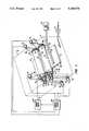
- FIG. 1schematically illustrates a dual cylindrical sputtering target magnetron that utilizes the improvement of the present invention
- FIG. 2shows in isometric view a portion of one of the target assemblies of FIG. 1;
- FIG. 3is a cross-section of a target assembly taken at section 3--3 of FIG. 2;
- FIG. 4is a partial sectional view of a preferred support assembly for a rotating target assembly of the type illustrated in FIGS. 1-3.
- a box 11shown in dotted outline, indicates metallic walls of a vacuum chamber in which the sputtering occurs.
- the target structures 13 and 15are generally held with their axes parallel to one another, but that is not a requirement.
- two target structuresare illustrated in FIG. 1, many applications need only employ one such target, and other applications can benefit by having more than two. However, the use of two target structures 13 and 15 is most common for most applications.
- the magnetron of FIG. 1is shown to have a substrate 17 held by a support structure 19.
- the support structure 19may be rollers to allow the substrate 17 to be passed through the vacuum chamber in a continuous process.
- a vacuumis drawn within the vacuum chamber by an appropriate pumping system 21.
- One or more gasesare provided by a supply 23 to the vacuum chamber by some convenient delivery system, such as a perforated tube 25 positioned across the vacuum chamber. The particular gases utilized depend primarily upon the film desired to be deposited on the substrate 17.
- Cylindrical pieces 27 and 29 of sputtering material provided as part of the target structures 13 and 15, respectively,are generally made of the same material but can be of different materials, depending upon the nature of the film to be deposited on the substrate 17.
- An electric motor source 31positioned outside the vacuum chamber, rotates the target assemblies by rotating, through a toothed belt 33, pulleys 35 and 37 which are attached to respective spindles 39 and 41.
- the sputtering materials 27 and 29are attached to the respective spindles 39 and 41 in order to rotate with them.
- a plasmais created within the vacuum chamber by applying a negative voltage from a power supply 40 to the sputtering surfaces with respect to the vacuum chamber metal frame 11 or some other anode, which is usually connected to ground potential.
- the plasmais positioned adjacent a sputtering zone of the cylindrical sputtering targets 27 and 29, controlled by the positioning of their respective magnets (not shown in FIG. 1). These magnets are positioned along the length of their respective cylindrical sputtering targets 27 and 29, while extending a small circumferential, or radial, distance therearound. These magnets are most conveniently held within the sputtering targets 27 and 29 by attachment to respective coolant conduits 43 and 45. These cooling conduits are provided as part of their respective target assemblies in a manner to be rotatable independently of rotation of their respective cylindrical sputtering targets 27 and 29.
- a pulley 47is attached to the conduit 43 and driven from an electrical motor source 49 outside the vacuum chamber by a toothed belt 51.
- a pulley 53is attached to the coolant conduit 45 and is controlled as to rotatable position by an electrical motor source 55 positioned outside the vacuum chamber and connected with it by a toothed belt 57.
- the motor sources 49 and 55are preferably stepper motors which thereby hold their respective conduits 43 and 45 in selected positions and keep them from rotating with their respective sputtering targets 27 and 29.
- a cooling liquid supply and exhaust system (not shown) outside the vacuum chamberprovides coolant into the center of each of the conduits 43 and 45, as indicated by an arrow 61, and exhausts the heated coolant from a space between the outside of the conduits and an interior surface of the spindles, as indicated by an arrow 63.
- An electrical and electronic control system 59operates to control the power supply 40 and various parameters of the magnetron system being shown, including motors 31, 49 and 55.
- the improvement of the present inventionis implemented in the system of FIG. 1 by providing cylindrically shaped shields 67 and 69 around and spaced from each of the cylindrical target surfaces 27 and 29, respectively. Additionally, the cylinders extend in length beyond the end of the sputtering material in order to cover exposed surfaces of adjacent spindles and their supporting structures. Window openings 72 and 74, in the respective shields 67 and 69, are large enough to expose the sputtering zone. These openings do not extend the full length of the cylindrical shields 67 and 69, however, leaving covered completely around their circumferences the respective sputtering surfaces 27 and 29 for a distance immediately adjacent the opposite ends of the sputtering material cylinder.
- the shields 67 and 69are then most easily held with their windows in a fixed position.
- the magnetsare made to be rotatable, as described in the embodiment of FIG. 1, such as is useful in the co-sputtering application previously mentioned, it is desirable to be able to controllably rotate the shields 67 and 69 so that their respective openings 72 and 74 follow the moving sputtering zone.
- the extend of shield rotationis made to be at least as great as the extend of magnet rotation. This allows the radial extent of the openings 72 and 74 to be kept small and thus maximize the coverage of the sputtering surface outside the sputtering zone.
- the shield 67is provided with a pulley 71 around its circumference near one end, and the shield 69 is similarly provided with a pulley 73.
- An electrical motor source 75rotates the shield 67 through a toothed belt 79, and a motor source 77 rotates the shield 69 through a toothed belt 81.
- the motor sources 75 and 77are preferably stepper motors and are also controlled by connection with the control system 59.
- Elongated magnets 85, 87 and 89are carried within the sputtering material cylinder 29 by a support structure 91 that is attached to the coolant tube 45.
- Each of this magnetic assembly, the sputtering tube 29 and the shield 69are independently rotatable about a longitudinal axis 93 by respective motor sources 55, 31 and 77.
- a specific supporting structure for a target assemblyis given.
- a cylindrical sputtering surface 95is carried through end spindles 97 and 99 in a manner to be rotatable about a longitudinal axis 101.
- a magnetic structure 103is positioned within the target cylinder 95.
- plates 105 and 107are provided at opposite ends of the target assembly. These end plates carry respective annular groves 109 and 111 into which a cylindrically shaped shield 113 is inserted at its ends. The shield 113 is then easily rotatable by a motor source connected to a pulley 115.
- This support arrangement for the shield 113also has an advantage of covering portions of the end plates 105 and 107 that are immediately adjacent ends of the sputtering target cylinder 95. These supporting structure surfaces are particularly susceptible to deposition of undesirable films on them, because of their proximity to the plasma sputtering zone, so are very useful for this purpose. Additionally, as previously mentioned, end portions 117 and 119 are circumferentially continuous around the shield and extend far enough along its length to cover respective end portions of the sputtering target 95 where the self-cleaning action of a rotating target act as effectively as it does in more central portions of the target's length. A window 121 is provided, however, in the shield 113 to expose at least the sputtering zone.
- the shield 113is preferably made of a material that itself has a low sputtering yield, such as stainless steel.
Landscapes
- Chemical & Material Sciences (AREA)
- Engineering & Computer Science (AREA)
- Physics & Mathematics (AREA)
- Plasma & Fusion (AREA)
- Analytical Chemistry (AREA)
- Chemical Kinetics & Catalysis (AREA)
- Materials Engineering (AREA)
- Mechanical Engineering (AREA)
- Metallurgy (AREA)
- Organic Chemistry (AREA)
- Physical Vapour Deposition (AREA)
Abstract
Description
Claims (12)
Priority Applications (2)
| Application Number | Priority Date | Filing Date | Title |
|---|---|---|---|
| US07/647,391US5108574A (en) | 1991-01-29 | 1991-01-29 | Cylindrical magnetron shield structure |
| JP4013979AJPH0565636A (en) | 1991-01-29 | 1992-01-29 | Cylindrical magnetron shield structure |
Applications Claiming Priority (1)
| Application Number | Priority Date | Filing Date | Title |
|---|---|---|---|
| US07/647,391US5108574A (en) | 1991-01-29 | 1991-01-29 | Cylindrical magnetron shield structure |
Publications (1)
| Publication Number | Publication Date |
|---|---|
| US5108574Atrue US5108574A (en) | 1992-04-28 |
Family
ID=24596813
Family Applications (1)
| Application Number | Title | Priority Date | Filing Date |
|---|---|---|---|
| US07/647,391Expired - Fee RelatedUS5108574A (en) | 1991-01-29 | 1991-01-29 | Cylindrical magnetron shield structure |
Country Status (2)
| Country | Link |
|---|---|
| US (1) | US5108574A (en) |
| JP (1) | JPH0565636A (en) |
Cited By (63)
| Publication number | Priority date | Publication date | Assignee | Title |
|---|---|---|---|---|
| US5213672A (en)* | 1991-05-29 | 1993-05-25 | Leybold Aktiengesellschaft | Sputtering apparatus with a rotating target |
| EP0589699A1 (en)* | 1992-09-29 | 1994-03-30 | The Boc Group, Inc. | Device and method for depositing metal oxide films |
| WO1994016118A1 (en)* | 1993-01-15 | 1994-07-21 | The Boc Group, Inc. | Cylindrical magnetron shield structure |
| US5405517A (en)* | 1993-12-06 | 1995-04-11 | Curtis M. Lampkin | Magnetron sputtering method and apparatus for compound thin films |
| EP0674337A1 (en)* | 1994-03-23 | 1995-09-27 | The Boc Group, Inc. | Magnetron sputtering methods and apparatus |
| WO1996006205A1 (en)* | 1994-08-24 | 1996-02-29 | Viratec Thin Films, Inc. | Spring-loaded mount for a rotatable sputtering cathode |
| US5527439A (en)* | 1995-01-23 | 1996-06-18 | The Boc Group, Inc. | Cylindrical magnetron shield structure |
| US5539272A (en)* | 1993-12-30 | 1996-07-23 | Viratec Thin Films, Inc. | Rotating floating magnetron dark-space shield |
| WO1996034124A1 (en)* | 1995-04-25 | 1996-10-31 | The Boc Group, Inc. | Sputtering system using cylindrical rotating magnetron electrically powered using alternating current |
| US5620577A (en)* | 1993-12-30 | 1997-04-15 | Viratec Thin Films, Inc. | Spring-loaded mount for a rotatable sputtering cathode |
| US5645699A (en)* | 1994-09-06 | 1997-07-08 | The Boc Group, Inc. | Dual cylindrical target magnetron with multiple anodes |
| WO2000028104A1 (en)* | 1998-11-06 | 2000-05-18 | Scivac | Sputtering apparatus and process for high rate coatings |
| DE10145201C1 (en)* | 2001-09-13 | 2002-11-21 | Fraunhofer Ges Forschung | Device for coating substrates having a curved surface contains a pair of rectangular magnetron sources and substrate holders arranged in an evacuated chamber |
| US6488824B1 (en)* | 1998-11-06 | 2002-12-03 | Raycom Technologies, Inc. | Sputtering apparatus and process for high rate coatings |
| US20030085122A1 (en)* | 2001-11-05 | 2003-05-08 | Nobuyuki Takahashi | Sputtering device |
| US6582572B2 (en) | 2000-06-01 | 2003-06-24 | Seagate Technology Llc | Target fabrication method for cylindrical cathodes |
| US6736948B2 (en) | 2002-01-18 | 2004-05-18 | Von Ardenne Anlagentechnik Gmbh | Cylindrical AC/DC magnetron with compliant drive system and improved electrical and thermal isolation |
| US20040118678A1 (en)* | 2002-12-18 | 2004-06-24 | Klaus Hartig | Magnetron sputtering systems including anodic gas distribution systems |
| US20040129561A1 (en)* | 2003-01-07 | 2004-07-08 | Von Ardenne Anlagentechnik Gmbh | Cylindrical magnetron magnetic array mid span support |
| US20050051422A1 (en)* | 2003-02-21 | 2005-03-10 | Rietzel James G. | Cylindrical magnetron with self cleaning target |
| US20050137084A1 (en)* | 2003-12-22 | 2005-06-23 | Krisko Annette J. | Graded photocatalytic coatings |
| US20050224343A1 (en)* | 2004-04-08 | 2005-10-13 | Richard Newcomb | Power coupling for high-power sputtering |
| US20060057298A1 (en)* | 2004-07-12 | 2006-03-16 | Krisko Annette J | Low-maintenance coatings |
| US7014741B2 (en) | 2003-02-21 | 2006-03-21 | Von Ardenne Anlagentechnik Gmbh | Cylindrical magnetron with self cleaning target |
| US20060065524A1 (en)* | 2004-09-30 | 2006-03-30 | Richard Newcomb | Non-bonded rotatable targets for sputtering |
| US20060096855A1 (en)* | 2004-11-05 | 2006-05-11 | Richard Newcomb | Cathode arrangement for atomizing a rotatable target pipe |
| US20060118408A1 (en)* | 2004-12-03 | 2006-06-08 | Kari Myli | Methods and equipment for depositing hydrophilic coatings, and deposition technologies for thin films |
| US20060121315A1 (en)* | 2004-12-03 | 2006-06-08 | Kari Myli | Hydrophilic coatings, methods for depositing hydrophilic coatings, and improved deposition technology for thin films |
| US20060124446A1 (en)* | 2002-10-15 | 2006-06-15 | Othmar Zuger | Method for the production of a substrate with a magnetron sputter coating and unit for the same |
| US20060137968A1 (en)* | 2004-12-27 | 2006-06-29 | Klaus Hartig | Oscillating shielded cylindrical target assemblies and their methods of use |
| US20060278519A1 (en)* | 2005-06-10 | 2006-12-14 | Leszek Malaszewski | Adaptable fixation for cylindrical magnetrons |
| US20060278524A1 (en)* | 2005-06-14 | 2006-12-14 | Stowell Michael W | System and method for modulating power signals to control sputtering |
| US20060278521A1 (en)* | 2005-06-14 | 2006-12-14 | Stowell Michael W | System and method for controlling ion density and energy using modulated power signals |
| US20070098916A1 (en)* | 2005-11-01 | 2007-05-03 | Stowell Michael W | System and method for modulation of power and power related functions of PECVD discharge sources to achieve new film properties |
| US20070095281A1 (en)* | 2005-11-01 | 2007-05-03 | Stowell Michael W | System and method for power function ramping of microwave liner discharge sources |
| US20070158180A1 (en)* | 2004-06-07 | 2007-07-12 | Ulvac, Inc. | Magnetron sputtering method and magnetron sputtering apparatus |
| US20080067057A1 (en)* | 2006-09-15 | 2008-03-20 | John German | Enhanced virtual anode |
| US20080289957A1 (en)* | 2004-09-14 | 2008-11-27 | Shinmaywa Industries, Ltd. | Vacuum Film Forming Apparatus |
| US20090130336A1 (en)* | 2006-03-28 | 2009-05-21 | Nv Bekaert Sa | Coating apparatus |
| CN101565278A (en)* | 2009-05-08 | 2009-10-28 | 浙江大学 | Double-sided sputtering silvered device of barrel-type quartz crystal |
| US20100187104A1 (en)* | 2007-06-25 | 2010-07-29 | Kabushiki Kaisha Kobe Seiko Sho(Kobe Steel, Ltd.) | Film formation apparatus |
| US20100243428A1 (en)* | 2009-03-27 | 2010-09-30 | Sputtering Components, Inc. | Rotary cathode for magnetron sputtering apparatus |
| US20100278683A1 (en)* | 2002-09-30 | 2010-11-04 | Miasole | Manufacturing Apparatus and Method for Large-Scale Production of Thin-Film Solar Cells |
| US20100326817A1 (en)* | 2007-09-14 | 2010-12-30 | Cardinal Cg Company | Low-maintenance coatings, and methods for producing low-maintenance coatings |
| US20110005923A1 (en)* | 2009-07-13 | 2011-01-13 | Applied Materials, Inc. | Sputtering system, rotatable cylindrical target assembly, backing tube, target element and cooling shield |
| BE1018645A5 (en)* | 2007-09-24 | 2011-06-07 | Ardenne Anlagentech Gmbh | MAGNETRON SYSTEM WITH TARGET ARMOR SUPPORT. |
| US7989094B2 (en) | 2006-04-19 | 2011-08-02 | Cardinal Cg Company | Opposed functional coatings having comparable single surface reflectances |
| US20130129937A1 (en)* | 2011-11-23 | 2013-05-23 | United Technologies Corporation | Vapor Deposition of Ceramic Coatings |
| US20140179022A1 (en)* | 2012-12-21 | 2014-06-26 | Luminex Corporation | Rotating shielded magnetic actuator |
| CN103917690A (en)* | 2011-08-04 | 2014-07-09 | 零件喷涂公司 | Rotating cathode of a magnetron sputtering system |
| CN104342623A (en)* | 2013-07-25 | 2015-02-11 | 三星显示有限公司 | Sputtering device and method for forming thin film thereby |
| CN104342622A (en)* | 2013-07-24 | 2015-02-11 | 三星显示有限公司 | Sputtering device |
| KR20160087986A (en)* | 2015-01-14 | 2016-07-25 | 삼성디스플레이 주식회사 | Magnetron sputtering apparatus |
| US20170047204A1 (en)* | 2013-03-13 | 2017-02-16 | Bb Plasma Design Ab | Magnetron plasma apparatus |
| DE102015117845A1 (en)* | 2015-10-20 | 2017-04-20 | Von Ardenne Gmbh | Method and arrangement for coating a substrate |
| US9738967B2 (en) | 2006-07-12 | 2017-08-22 | Cardinal Cg Company | Sputtering apparatus including target mounting and control |
| WO2018095514A1 (en)* | 2016-11-22 | 2018-05-31 | Applied Materials, Inc. | Apparatus and method for layer deposition on a substrate |
| US10604442B2 (en) | 2016-11-17 | 2020-03-31 | Cardinal Cg Company | Static-dissipative coating technology |
| US20210285090A1 (en)* | 2020-03-16 | 2021-09-16 | Vapor Technologies, Inc. | Convertible magnetics for rotary cathode |
| JP2021143353A (en)* | 2020-03-10 | 2021-09-24 | 株式会社Screenホールディングス | Sputtering device and sputtering method |
| US11414746B2 (en)* | 2018-07-02 | 2022-08-16 | Canon Kabushiki Kaisha | Film forming apparatus and film forming method using the same |
| US11501959B2 (en) | 2015-02-03 | 2022-11-15 | Cardinal Cg Company | Sputtering apparatus including gas distribution system |
| CN119040823A (en)* | 2024-08-22 | 2024-11-29 | 中国科学技术大学 | Getter coating method and device for elliptic vacuum box for synchrotron radiation light source |
Families Citing this family (7)
| Publication number | Priority date | Publication date | Assignee | Title |
|---|---|---|---|---|
| KR100674005B1 (en)* | 2005-07-01 | 2007-01-24 | 주식회사 에스에프에이 | Sputtering Sources and Sputters with the Same |
| JP2014058698A (en)* | 2010-12-15 | 2014-04-03 | Canon Anelva Corp | Sputtering device |
| US20140332369A1 (en)* | 2011-10-24 | 2014-11-13 | Applied Materials, Inc. | Multidirectional racetrack rotary cathode for pvd array applications |
| KR101950857B1 (en)* | 2015-06-05 | 2019-02-21 | 어플라이드 머티어리얼스, 인코포레이티드 | Sputter deposition source, sputtering apparatus and method of operating thereof |
| JP6396367B2 (en)* | 2016-06-27 | 2018-09-26 | アプライド マテリアルズ インコーポレイテッドApplied Materials,Incorporated | Multi-directional racetrack rotating cathode for PVD arrays |
| JP6957270B2 (en)* | 2017-08-31 | 2021-11-02 | 株式会社Screenホールディングス | Film formation equipment and film formation method |
| KR102149656B1 (en)* | 2018-08-10 | 2020-08-31 | 주식회사 선익시스템 | Deposition Equipment Including Means Having Covering Formation for Restraining Arc |
Citations (13)
| Publication number | Priority date | Publication date | Assignee | Title |
|---|---|---|---|---|
| US4356073A (en)* | 1981-02-12 | 1982-10-26 | Shatterproof Glass Corporation | Magnetron cathode sputtering apparatus |
| DE3229969A1 (en)* | 1981-10-02 | 1983-04-21 | VEB Zentrum für Forschung und Technologie Mikroelektronik, DDR 8080 Dresden | Device for high-rate atomization using the plasmatron principle |
| US4410407A (en)* | 1981-12-22 | 1983-10-18 | Raytheon Company | Sputtering apparatus and methods |
| US4417968A (en)* | 1983-03-21 | 1983-11-29 | Shatterproof Glass Corporation | Magnetron cathode sputtering apparatus |
| US4422916A (en)* | 1981-02-12 | 1983-12-27 | Shatterproof Glass Corporation | Magnetron cathode sputtering apparatus |
| US4443318A (en)* | 1983-08-17 | 1984-04-17 | Shatterproof Glass Corporation | Cathodic sputtering apparatus |
| US4444643A (en)* | 1982-09-03 | 1984-04-24 | Gartek Systems, Inc. | Planar magnetron sputtering device |
| US4466877A (en)* | 1983-10-11 | 1984-08-21 | Shatterproof Glass Corporation | Magnetron cathode sputtering apparatus |
| US4498969A (en)* | 1982-11-18 | 1985-02-12 | Canadian Patents And Development Limited-Societe Candienne Des Brevets Et D'exploitation (Limitee | Sputtering apparatus and method |
| US4746417A (en)* | 1986-06-06 | 1988-05-24 | Leybold-Heraeus Gmbh | Magnetron sputtering cathode for vacuum coating apparatus |
| JPS63149374A (en)* | 1986-12-12 | 1988-06-22 | Fujitsu Ltd | Sputtering device |
| CA1239115A (en)* | 1987-10-29 | 1988-07-12 | Canadian Patents And Development Limited - Societe Canadienne Des Brevets Et D'exploitation Limitee | Sputtering apparatus and method |
| US4872964A (en)* | 1985-08-02 | 1989-10-10 | Fujitsu Limited | Planar magnetron sputtering apparatus and its magnetic source |
- 1991
- 1991-01-29USUS07/647,391patent/US5108574A/ennot_activeExpired - Fee Related
- 1992
- 1992-01-29JPJP4013979Apatent/JPH0565636A/enactivePending
Patent Citations (13)
| Publication number | Priority date | Publication date | Assignee | Title |
|---|---|---|---|---|
| US4356073A (en)* | 1981-02-12 | 1982-10-26 | Shatterproof Glass Corporation | Magnetron cathode sputtering apparatus |
| US4422916A (en)* | 1981-02-12 | 1983-12-27 | Shatterproof Glass Corporation | Magnetron cathode sputtering apparatus |
| DE3229969A1 (en)* | 1981-10-02 | 1983-04-21 | VEB Zentrum für Forschung und Technologie Mikroelektronik, DDR 8080 Dresden | Device for high-rate atomization using the plasmatron principle |
| US4410407A (en)* | 1981-12-22 | 1983-10-18 | Raytheon Company | Sputtering apparatus and methods |
| US4444643A (en)* | 1982-09-03 | 1984-04-24 | Gartek Systems, Inc. | Planar magnetron sputtering device |
| US4498969A (en)* | 1982-11-18 | 1985-02-12 | Canadian Patents And Development Limited-Societe Candienne Des Brevets Et D'exploitation (Limitee | Sputtering apparatus and method |
| US4417968A (en)* | 1983-03-21 | 1983-11-29 | Shatterproof Glass Corporation | Magnetron cathode sputtering apparatus |
| US4443318A (en)* | 1983-08-17 | 1984-04-17 | Shatterproof Glass Corporation | Cathodic sputtering apparatus |
| US4466877A (en)* | 1983-10-11 | 1984-08-21 | Shatterproof Glass Corporation | Magnetron cathode sputtering apparatus |
| US4872964A (en)* | 1985-08-02 | 1989-10-10 | Fujitsu Limited | Planar magnetron sputtering apparatus and its magnetic source |
| US4746417A (en)* | 1986-06-06 | 1988-05-24 | Leybold-Heraeus Gmbh | Magnetron sputtering cathode for vacuum coating apparatus |
| JPS63149374A (en)* | 1986-12-12 | 1988-06-22 | Fujitsu Ltd | Sputtering device |
| CA1239115A (en)* | 1987-10-29 | 1988-07-12 | Canadian Patents And Development Limited - Societe Canadienne Des Brevets Et D'exploitation Limitee | Sputtering apparatus and method |
Non-Patent Citations (4)
| Title |
|---|
| Chapman, "Practical Aspects of Sputtering Systems", pp. 196-198, Chapter 6: "Sputtering", in Glow Discharge Processes, John Wiley & Sons, 1980. |
| Chapman, Practical Aspects of Sputtering Systems , pp. 196 198, Chapter 6: Sputtering , in Glow Discharge Processes, John Wiley & Sons, 1980.* |
| Wright et al., "Design . . . magnetron", J. Vac. Sci. Technol. A, vol. 4, No. 3, May/Jun. 1986, pp. 388-392. |
| Wright et al., Design . . . magnetron , J. Vac. Sci. Technol. A, vol. 4, No. 3, May/Jun. 1986, pp. 388 392.* |
Cited By (105)
| Publication number | Priority date | Publication date | Assignee | Title |
|---|---|---|---|---|
| US5213672A (en)* | 1991-05-29 | 1993-05-25 | Leybold Aktiengesellschaft | Sputtering apparatus with a rotating target |
| EP0589699A1 (en)* | 1992-09-29 | 1994-03-30 | The Boc Group, Inc. | Device and method for depositing metal oxide films |
| US5338422A (en)* | 1992-09-29 | 1994-08-16 | The Boc Group, Inc. | Device and method for depositing metal oxide films |
| AU678213B2 (en)* | 1993-01-15 | 1997-05-22 | Boc Group, Inc., The | Cylindrical magnetron shield structure |
| WO1994016118A1 (en)* | 1993-01-15 | 1994-07-21 | The Boc Group, Inc. | Cylindrical magnetron shield structure |
| US5464518A (en)* | 1993-01-15 | 1995-11-07 | The Boc Group, Inc. | Cylindrical magnetron shield structure |
| EP1251547A1 (en)* | 1993-01-15 | 2002-10-23 | The Boc Group, Inc. | Cylindrical magnetron shield structure |
| KR100325969B1 (en)* | 1993-01-15 | 2002-08-08 | 더 비오씨 그룹 인코포레이티드 | Sputtering Device and Cylindrical End Protection Device Formation Method and Sputter Etching Method |
| US5405517A (en)* | 1993-12-06 | 1995-04-11 | Curtis M. Lampkin | Magnetron sputtering method and apparatus for compound thin films |
| WO1995016058A1 (en)* | 1993-12-06 | 1995-06-15 | Lampkin Curtis M | Magnetron sputtering apparatus for compound thin films |
| US5539272A (en)* | 1993-12-30 | 1996-07-23 | Viratec Thin Films, Inc. | Rotating floating magnetron dark-space shield |
| US5620577A (en)* | 1993-12-30 | 1997-04-15 | Viratec Thin Films, Inc. | Spring-loaded mount for a rotatable sputtering cathode |
| US5567289A (en)* | 1993-12-30 | 1996-10-22 | Viratec Thin Films, Inc. | Rotating floating magnetron dark-space shield and cone end |
| US5616225A (en)* | 1994-03-23 | 1997-04-01 | The Boc Group, Inc. | Use of multiple anodes in a magnetron for improving the uniformity of its plasma |
| EP0674337A1 (en)* | 1994-03-23 | 1995-09-27 | The Boc Group, Inc. | Magnetron sputtering methods and apparatus |
| WO1996006205A1 (en)* | 1994-08-24 | 1996-02-29 | Viratec Thin Films, Inc. | Spring-loaded mount for a rotatable sputtering cathode |
| US5645699A (en)* | 1994-09-06 | 1997-07-08 | The Boc Group, Inc. | Dual cylindrical target magnetron with multiple anodes |
| AU690388B2 (en)* | 1995-01-23 | 1998-04-23 | Boc Group, Inc., The | Cylindrical magnetron shield structure |
| US5527439A (en)* | 1995-01-23 | 1996-06-18 | The Boc Group, Inc. | Cylindrical magnetron shield structure |
| WO1996034124A1 (en)* | 1995-04-25 | 1996-10-31 | The Boc Group, Inc. | Sputtering system using cylindrical rotating magnetron electrically powered using alternating current |
| US5814195A (en)* | 1995-04-25 | 1998-09-29 | The Boc Group, Inc. | Sputtering system using cylindrical rotating magnetron electrically powered using alternating current |
| US6488824B1 (en)* | 1998-11-06 | 2002-12-03 | Raycom Technologies, Inc. | Sputtering apparatus and process for high rate coatings |
| WO2000028104A1 (en)* | 1998-11-06 | 2000-05-18 | Scivac | Sputtering apparatus and process for high rate coatings |
| US6582572B2 (en) | 2000-06-01 | 2003-06-24 | Seagate Technology Llc | Target fabrication method for cylindrical cathodes |
| DE10145201C1 (en)* | 2001-09-13 | 2002-11-21 | Fraunhofer Ges Forschung | Device for coating substrates having a curved surface contains a pair of rectangular magnetron sources and substrate holders arranged in an evacuated chamber |
| US20030085122A1 (en)* | 2001-11-05 | 2003-05-08 | Nobuyuki Takahashi | Sputtering device |
| US6800183B2 (en)* | 2001-11-05 | 2004-10-05 | Anelva Corporation | Sputtering device |
| US6736948B2 (en) | 2002-01-18 | 2004-05-18 | Von Ardenne Anlagentechnik Gmbh | Cylindrical AC/DC magnetron with compliant drive system and improved electrical and thermal isolation |
| US20050006233A1 (en)* | 2002-01-18 | 2005-01-13 | Barrett Richard L. | Cylindrical AC/DC magnetron with compliant drive system and improved electrical and thermal isolation |
| US20100278683A1 (en)* | 2002-09-30 | 2010-11-04 | Miasole | Manufacturing Apparatus and Method for Large-Scale Production of Thin-Film Solar Cells |
| US20060124446A1 (en)* | 2002-10-15 | 2006-06-15 | Othmar Zuger | Method for the production of a substrate with a magnetron sputter coating and unit for the same |
| US7381661B2 (en)* | 2002-10-15 | 2008-06-03 | Oc Oerlikon Balzers Ag | Method for the production of a substrate with a magnetron sputter coating and unit for the same |
| US20040118678A1 (en)* | 2002-12-18 | 2004-06-24 | Klaus Hartig | Magnetron sputtering systems including anodic gas distribution systems |
| US7166199B2 (en) | 2002-12-18 | 2007-01-23 | Cardinal Cg Company | Magnetron sputtering systems including anodic gas distribution systems |
| US20040129561A1 (en)* | 2003-01-07 | 2004-07-08 | Von Ardenne Anlagentechnik Gmbh | Cylindrical magnetron magnetic array mid span support |
| WO2004061894A1 (en)* | 2003-01-07 | 2004-07-22 | Von Ardenne Anlagentechnik Gmbh | Mid span support for a magnetic array of a cylindrical magnetron sputter device |
| US7014741B2 (en) | 2003-02-21 | 2006-03-21 | Von Ardenne Anlagentechnik Gmbh | Cylindrical magnetron with self cleaning target |
| US20050051422A1 (en)* | 2003-02-21 | 2005-03-10 | Rietzel James G. | Cylindrical magnetron with self cleaning target |
| US20050137084A1 (en)* | 2003-12-22 | 2005-06-23 | Krisko Annette J. | Graded photocatalytic coatings |
| US7294404B2 (en) | 2003-12-22 | 2007-11-13 | Cardinal Cg Company | Graded photocatalytic coatings |
| US20050224343A1 (en)* | 2004-04-08 | 2005-10-13 | Richard Newcomb | Power coupling for high-power sputtering |
| US20070158180A1 (en)* | 2004-06-07 | 2007-07-12 | Ulvac, Inc. | Magnetron sputtering method and magnetron sputtering apparatus |
| US7713632B2 (en) | 2004-07-12 | 2010-05-11 | Cardinal Cg Company | Low-maintenance coatings |
| US20060057401A1 (en)* | 2004-07-12 | 2006-03-16 | Krisko Annette J | Low-maintenance coatings |
| US20060057298A1 (en)* | 2004-07-12 | 2006-03-16 | Krisko Annette J | Low-maintenance coatings |
| USRE43817E1 (en) | 2004-07-12 | 2012-11-20 | Cardinal Cg Company | Low-maintenance coatings |
| US7604865B2 (en) | 2004-07-12 | 2009-10-20 | Cardinal Cg Company | Low-maintenance coatings |
| USRE44155E1 (en) | 2004-07-12 | 2013-04-16 | Cardinal Cg Company | Low-maintenance coatings |
| US20080289957A1 (en)* | 2004-09-14 | 2008-11-27 | Shinmaywa Industries, Ltd. | Vacuum Film Forming Apparatus |
| US20060065524A1 (en)* | 2004-09-30 | 2006-03-30 | Richard Newcomb | Non-bonded rotatable targets for sputtering |
| US20060096855A1 (en)* | 2004-11-05 | 2006-05-11 | Richard Newcomb | Cathode arrangement for atomizing a rotatable target pipe |
| US20060118408A1 (en)* | 2004-12-03 | 2006-06-08 | Kari Myli | Methods and equipment for depositing hydrophilic coatings, and deposition technologies for thin films |
| US20060121315A1 (en)* | 2004-12-03 | 2006-06-08 | Kari Myli | Hydrophilic coatings, methods for depositing hydrophilic coatings, and improved deposition technology for thin films |
| US8092660B2 (en) | 2004-12-03 | 2012-01-10 | Cardinal Cg Company | Methods and equipment for depositing hydrophilic coatings, and deposition technologies for thin films |
| US7923114B2 (en) | 2004-12-03 | 2011-04-12 | Cardinal Cg Company | Hydrophilic coatings, methods for depositing hydrophilic coatings, and improved deposition technology for thin films |
| US20060137968A1 (en)* | 2004-12-27 | 2006-06-29 | Klaus Hartig | Oscillating shielded cylindrical target assemblies and their methods of use |
| US20060278519A1 (en)* | 2005-06-10 | 2006-12-14 | Leszek Malaszewski | Adaptable fixation for cylindrical magnetrons |
| US20060278521A1 (en)* | 2005-06-14 | 2006-12-14 | Stowell Michael W | System and method for controlling ion density and energy using modulated power signals |
| US20060278524A1 (en)* | 2005-06-14 | 2006-12-14 | Stowell Michael W | System and method for modulating power signals to control sputtering |
| US20070095281A1 (en)* | 2005-11-01 | 2007-05-03 | Stowell Michael W | System and method for power function ramping of microwave liner discharge sources |
| US20070098916A1 (en)* | 2005-11-01 | 2007-05-03 | Stowell Michael W | System and method for modulation of power and power related functions of PECVD discharge sources to achieve new film properties |
| US20080286495A1 (en)* | 2005-11-01 | 2008-11-20 | Stowell Michael W | System and method for power function ramping of split antenna pecvd discharge sources |
| US7842355B2 (en) | 2005-11-01 | 2010-11-30 | Applied Materials, Inc. | System and method for modulation of power and power related functions of PECVD discharge sources to achieve new film properties |
| US20070098893A1 (en)* | 2005-11-01 | 2007-05-03 | Stowell Michael W | Coated substrate created by systems and methods for modulation of power and power related functions of PECVD discharge sources to achieve new film properties |
| US20090130336A1 (en)* | 2006-03-28 | 2009-05-21 | Nv Bekaert Sa | Coating apparatus |
| US8192597B2 (en)* | 2006-03-28 | 2012-06-05 | Nv Bekaert Sa | Coating apparatus |
| US7989094B2 (en) | 2006-04-19 | 2011-08-02 | Cardinal Cg Company | Opposed functional coatings having comparable single surface reflectances |
| US9738967B2 (en) | 2006-07-12 | 2017-08-22 | Cardinal Cg Company | Sputtering apparatus including target mounting and control |
| US7850828B2 (en) | 2006-09-15 | 2010-12-14 | Cardinal Cg Company | Enhanced virtual anode |
| US20080067057A1 (en)* | 2006-09-15 | 2008-03-20 | John German | Enhanced virtual anode |
| CN101688294B (en)* | 2007-06-25 | 2013-02-06 | 株式会社神户制钢所 | Film forming device |
| US20100187104A1 (en)* | 2007-06-25 | 2010-07-29 | Kabushiki Kaisha Kobe Seiko Sho(Kobe Steel, Ltd.) | Film formation apparatus |
| US20100326817A1 (en)* | 2007-09-14 | 2010-12-30 | Cardinal Cg Company | Low-maintenance coatings, and methods for producing low-maintenance coatings |
| US8506768B2 (en) | 2007-09-14 | 2013-08-13 | Cardinal Cg Company | Low-maintenance coatings, and methods for producing low-maintenance coatings |
| US8696879B2 (en) | 2007-09-14 | 2014-04-15 | Cardinal Cg Company | Low-maintenance coating technology |
| BE1018645A5 (en)* | 2007-09-24 | 2011-06-07 | Ardenne Anlagentech Gmbh | MAGNETRON SYSTEM WITH TARGET ARMOR SUPPORT. |
| US20100243428A1 (en)* | 2009-03-27 | 2010-09-30 | Sputtering Components, Inc. | Rotary cathode for magnetron sputtering apparatus |
| US8182662B2 (en) | 2009-03-27 | 2012-05-22 | Sputtering Components, Inc. | Rotary cathode for magnetron sputtering apparatus |
| CN101565278A (en)* | 2009-05-08 | 2009-10-28 | 浙江大学 | Double-sided sputtering silvered device of barrel-type quartz crystal |
| EP2276054A1 (en)* | 2009-07-13 | 2011-01-19 | Applied Materials, Inc. | Sputtering system, rotatable cylindrical target assembly, backing tube, target element and cooling shield |
| WO2011006799A1 (en)* | 2009-07-13 | 2011-01-20 | Applied Materials, Inc. | Sputtering system, rotatable cylindrical target assembly, backing tube, target element and cooling shield |
| US20110005923A1 (en)* | 2009-07-13 | 2011-01-13 | Applied Materials, Inc. | Sputtering system, rotatable cylindrical target assembly, backing tube, target element and cooling shield |
| CN103917690A (en)* | 2011-08-04 | 2014-07-09 | 零件喷涂公司 | Rotating cathode of a magnetron sputtering system |
| US20130129937A1 (en)* | 2011-11-23 | 2013-05-23 | United Technologies Corporation | Vapor Deposition of Ceramic Coatings |
| US20140179022A1 (en)* | 2012-12-21 | 2014-06-26 | Luminex Corporation | Rotating shielded magnetic actuator |
| US9752968B2 (en)* | 2012-12-21 | 2017-09-05 | Luminex Corporation | Rotating shielded magnetic actuator |
| US20170047204A1 (en)* | 2013-03-13 | 2017-02-16 | Bb Plasma Design Ab | Magnetron plasma apparatus |
| CN104342622A (en)* | 2013-07-24 | 2015-02-11 | 三星显示有限公司 | Sputtering device |
| CN104342623A (en)* | 2013-07-25 | 2015-02-11 | 三星显示有限公司 | Sputtering device and method for forming thin film thereby |
| CN104342623B (en)* | 2013-07-25 | 2018-11-23 | 三星显示有限公司 | Sputtering equipment and the method for forming film with it |
| US9558921B2 (en)* | 2015-01-14 | 2017-01-31 | Samsung Display Co., Ltd. | Magnetron sputtering apparatus |
| KR20160087986A (en)* | 2015-01-14 | 2016-07-25 | 삼성디스플레이 주식회사 | Magnetron sputtering apparatus |
| US11674213B2 (en) | 2015-02-03 | 2023-06-13 | Cardinal Cg Company | Sputtering apparatus including gas distribution system |
| US11501959B2 (en) | 2015-02-03 | 2022-11-15 | Cardinal Cg Company | Sputtering apparatus including gas distribution system |
| DE102015117845A1 (en)* | 2015-10-20 | 2017-04-20 | Von Ardenne Gmbh | Method and arrangement for coating a substrate |
| US10604442B2 (en) | 2016-11-17 | 2020-03-31 | Cardinal Cg Company | Static-dissipative coating technology |
| US11325859B2 (en) | 2016-11-17 | 2022-05-10 | Cardinal Cg Company | Static-dissipative coating technology |
| WO2018095514A1 (en)* | 2016-11-22 | 2018-05-31 | Applied Materials, Inc. | Apparatus and method for layer deposition on a substrate |
| CN109983150A (en)* | 2016-11-22 | 2019-07-05 | 应用材料公司 | Apparatus and method for depositing layers on substrates |
| CN109983150B (en)* | 2016-11-22 | 2022-04-26 | 应用材料公司 | Apparatus and method for depositing layers on substrates |
| US11414746B2 (en)* | 2018-07-02 | 2022-08-16 | Canon Kabushiki Kaisha | Film forming apparatus and film forming method using the same |
| JP2021143353A (en)* | 2020-03-10 | 2021-09-24 | 株式会社Screenホールディングス | Sputtering device and sputtering method |
| US11629399B2 (en)* | 2020-03-16 | 2023-04-18 | Vapor Technologies, Inc. | Convertible magnetics for rotary cathode |
| US20210285090A1 (en)* | 2020-03-16 | 2021-09-16 | Vapor Technologies, Inc. | Convertible magnetics for rotary cathode |
| CN119040823A (en)* | 2024-08-22 | 2024-11-29 | 中国科学技术大学 | Getter coating method and device for elliptic vacuum box for synchrotron radiation light source |
Also Published As
| Publication number | Publication date |
|---|---|
| JPH0565636A (en) | 1993-03-19 |
Similar Documents
| Publication | Publication Date | Title |
|---|---|---|
| US5108574A (en) | Cylindrical magnetron shield structure | |
| US5464518A (en) | Cylindrical magnetron shield structure | |
| JP2556637B2 (en) | Deposition system on substrate by magnetron cathode | |
| US5470452A (en) | Shielding for arc suppression in rotating magnetron sputtering systems | |
| US6197165B1 (en) | Method and apparatus for ionized physical vapor deposition | |
| JP2002529600A (en) | Sputtering apparatus and method for high rate coating | |
| JP2000073168A (en) | Multilayer pvd film forming apparatus for substrate and method therefor | |
| EP1999292A1 (en) | Sputtering apparatus | |
| US5753089A (en) | Sputter coating station | |
| GB2310434A (en) | Cathode sputtering | |
| US5328582A (en) | Off-axis magnetron sputter deposition of mirrors | |
| US12176191B2 (en) | Magnetron design for improved bottom coverage and uniformity | |
| JPH0688229A (en) | Electric control for rotation of magnetic zone of spattering target in double cylindrical magnetron | |
| HK1008111B (en) | Magnetron sputtering device and method for thin film coating | |
| JPH1030180A (en) | Magnetron source and plasma processing system | |
| EP0537012A1 (en) | Sputtering processes and apparatus | |
| JPH03140467A (en) | Sputtering device | |
| JPS6116346B2 (en) | ||
| JPH10287977A (en) | Sputtering equipment | |
| JPS6353261A (en) | Plasma treatment device | |
| JP3229251B2 (en) | CVD equipment | |
| JPH05230648A (en) | Sputtering device | |
| JP2002020866A (en) | Sputtering system | |
| JPS61124133A (en) | plasma processing equipment | |
| JP2000199061A (en) | Electronic cyclotron resonance plasma sputtering device, and manufacture of thin film |
Legal Events
| Date | Code | Title | Description |
|---|---|---|---|
| AS | Assignment | Owner name:BOC GROUP, INC., THE, 575 MOUNTAIN AVENUE, MURRAY Free format text:ASSIGNMENT OF ASSIGNORS INTEREST.;ASSIGNORS:KIRS, MILAN R.;BELKIND, ABRAHAM I.;KURIE, J. RANDALL;AND OTHERS;REEL/FRAME:005610/0591;SIGNING DATES FROM 19910124 TO 19910129 | |
| FEPP | Fee payment procedure | Free format text:PAYOR NUMBER ASSIGNED (ORIGINAL EVENT CODE: ASPN); ENTITY STATUS OF PATENT OWNER: LARGE ENTITY | |
| FPAY | Fee payment | Year of fee payment:4 | |
| FPAY | Fee payment | Year of fee payment:8 | |
| REMI | Maintenance fee reminder mailed | ||
| LAPS | Lapse for failure to pay maintenance fees | ||
| FP | Lapsed due to failure to pay maintenance fee | Effective date:20040428 | |
| AS | Assignment | Owner name:COATING INDUSTRIES INVESTMENT CORP., CALIFORNIA Free format text:EXCLUSIVE LICENSE AGREEMENT;ASSIGNOR:VON ARDENNE ANLAGENTECHNIK GMBH;REEL/FRAME:015334/0545 Effective date:20040730 | |
| AS | Assignment | Owner name:COATING INDUSTRIES INVESTMENT CORP., CALIFORNIA Free format text:NON-EXCLUSIVE LICENSE AGREEMENT *UNNECESSARY PORTI;ASSIGNOR:VON ARDENNE ANLAGENTECHNIK GMBH;REEL/FRAME:015348/0270 Effective date:20040730 | |
| AS | Assignment | Owner name:COATING INDUSTRIES INVESTMENT CORP., CALIFORNIA Free format text:ASSIGNMENT OF ASSIGNORS INTEREST;ASSIGNOR:VON ARDENNE ANLAGENTECHNIK GMBH;REEL/FRAME:016386/0711 Effective date:20040730 | |
| AS | Assignment | Owner name:VON ARDENNE ANLAGENTECHNIK GMBH, GERMANY Free format text:ASSIGNMENT OF ASSIGNORS INTEREST;ASSIGNOR:BOC GROUP, INC., THE;REEL/FRAME:016745/0833 Effective date:20020404 | |
| AS | Assignment | Owner name:APPLIED FILMS CORPORATION, COLORADO Free format text:MERGER;ASSIGNOR:COATING INDUSTRIES INVESTMENT CORP.;REEL/FRAME:017507/0246 Effective date:20051128 | |
| STCH | Information on status: patent discontinuation | Free format text:PATENT EXPIRED DUE TO NONPAYMENT OF MAINTENANCE FEES UNDER 37 CFR 1.362 |