US5108213A - Clamping assembly - Google Patents
Clamping assemblyDownload PDFInfo
- Publication number
- US5108213A US5108213AUS07/673,942US67394291AUS5108213AUS 5108213 AUS5108213 AUS 5108213AUS 67394291 AUS67394291 AUS 67394291AUS 5108213 AUS5108213 AUS 5108213A
- Authority
- US
- United States
- Prior art keywords
- shaft
- support rod
- locking ring
- clamping assembly
- housing
- Prior art date
- Legal status (The legal status is an assumption and is not a legal conclusion. Google has not performed a legal analysis and makes no representation as to the accuracy of the status listed.)
- Expired - Lifetime
Links
- 238000006073displacement reactionMethods0.000claimsabstractdescription16
- 230000006835compressionEffects0.000claimsabstractdescription9
- 238000007906compressionMethods0.000claimsabstractdescription9
- 230000001105regulatory effectEffects0.000claimsabstractdescription6
- 238000004873anchoringMethods0.000claims2
- 230000001276controlling effectEffects0.000abstractdescription3
- 230000003993interactionEffects0.000abstractdescription2
- 230000000452restraining effectEffects0.000description2
- 208000027418Wounds and injuryDiseases0.000description1
- XAGFODPZIPBFFR-UHFFFAOYSA-NaluminiumChemical compound[Al]XAGFODPZIPBFFR-UHFFFAOYSA-N0.000description1
- 229910052782aluminiumInorganic materials0.000description1
- 230000000712assemblyEffects0.000description1
- 238000000429assemblyMethods0.000description1
- 238000010276constructionMethods0.000description1
- 230000006378damageEffects0.000description1
- 230000009977dual effectEffects0.000description1
- 208000014674injuryDiseases0.000description1
- 238000003780insertionMethods0.000description1
- 230000037431insertionEffects0.000description1
- 238000004519manufacturing processMethods0.000description1
- 239000000463materialSubstances0.000description1
- 238000012986modificationMethods0.000description1
- 230000004048modificationEffects0.000description1
- 230000001681protective effectEffects0.000description1
- 239000010935stainless steelSubstances0.000description1
- 229910001220stainless steelInorganic materials0.000description1
- 238000001356surgical procedureMethods0.000description1
Images
Classifications
- A—HUMAN NECESSITIES
- A61—MEDICAL OR VETERINARY SCIENCE; HYGIENE
- A61G—TRANSPORT, PERSONAL CONVEYANCES, OR ACCOMMODATION SPECIALLY ADAPTED FOR PATIENTS OR DISABLED PERSONS; OPERATING TABLES OR CHAIRS; CHAIRS FOR DENTISTRY; FUNERAL DEVICES
- A61G13/00—Operating tables; Auxiliary appliances therefor
- A61G13/10—Parts, details or accessories
- A61G13/101—Clamping means for connecting accessories to the operating table
- B—PERFORMING OPERATIONS; TRANSPORTING
- B25—HAND TOOLS; PORTABLE POWER-DRIVEN TOOLS; MANIPULATORS
- B25B—TOOLS OR BENCH DEVICES NOT OTHERWISE PROVIDED FOR, FOR FASTENING, CONNECTING, DISENGAGING OR HOLDING
- B25B5/00—Clamps
- B25B5/006—Supporting devices for clamps
- F—MECHANICAL ENGINEERING; LIGHTING; HEATING; WEAPONS; BLASTING
- F16—ENGINEERING ELEMENTS AND UNITS; GENERAL MEASURES FOR PRODUCING AND MAINTAINING EFFECTIVE FUNCTIONING OF MACHINES OR INSTALLATIONS; THERMAL INSULATION IN GENERAL
- F16M—FRAMES, CASINGS OR BEDS OF ENGINES, MACHINES OR APPARATUS, NOT SPECIFIC TO ENGINES, MACHINES OR APPARATUS PROVIDED FOR ELSEWHERE; STANDS; SUPPORTS
- F16M13/00—Other supports for positioning apparatus or articles; Means for steadying hand-held apparatus or articles
- F16M13/02—Other supports for positioning apparatus or articles; Means for steadying hand-held apparatus or articles for supporting on, or attaching to, an object, e.g. tree, gate, window-frame, cycle
- Y—GENERAL TAGGING OF NEW TECHNOLOGICAL DEVELOPMENTS; GENERAL TAGGING OF CROSS-SECTIONAL TECHNOLOGIES SPANNING OVER SEVERAL SECTIONS OF THE IPC; TECHNICAL SUBJECTS COVERED BY FORMER USPC CROSS-REFERENCE ART COLLECTIONS [XRACs] AND DIGESTS
- Y10—TECHNICAL SUBJECTS COVERED BY FORMER USPC
- Y10T—TECHNICAL SUBJECTS COVERED BY FORMER US CLASSIFICATION
- Y10T403/00—Joints and connections
- Y10T403/32—Articulated members
- Y10T403/32008—Plural distinct articulation axes
- Y10T403/32057—Angular and linear
Definitions
- This inventionrelates generally to clamping assemblies, and in particular to a clamping assembly for adjustably connecting accessories, such as hangers, stirrups, or arm supports, to the rail of a medical table via a support rod, the clamping assembly including independent adjustment means for rotating and longitudinally displacing the support rod relative to the medical table.
- clamping deviceshave been developed for adjustably securing accessories to the side rail or track of a medical table. Most of these devices are designed to perform two primary clamping functions: 1) adjustably clamping the device to the rail or track; and 2) adjustably clamping the accessory to the device. These clamping functions are performed in various ways.
- U.S. Pat. No. 4,547,092issued to Vetter et al. on Oct. 15, 1985, discloses an accessory clamp for a medical table that includes an adjustment mechanism for securing the clamp to the table and another adjustment mechanism for adjusting the relationship of the accessory to the table.
- the mechanism for securing the clamp to the tableincludes a control knob with a threaded socket that receives the threaded end of a control shaft that extends completely through the bore of the clamp.
- the opposite end of the shaftincludes a contact member received within a recess formed within the base of the clamp.
- the control knobcan be used to move the contact member longitudinally thereby tightening or loosening the clamp relative to the track or rail of a medical table.
- the adjustment mechanism of Vetter et al. pertaining to the accessoryincludes an inner base section and an outer cup section, each containing an annular row of circumferentially arranged teeth that cooperate with each other.
- a rod for supporting an accessoryis inserted through an off-centered opening in the cup section.
- a handwheelis used to wedge the support rod tightly in place within the opening.
- the handwheelis also used to engage or disengage the inner base section with the outer cup section so the accessory can be locked into place or swiveled. Tightening or loosening the handwheel performs the dual functions of locking or releasing both the support rod of the accessory and the swivel mechanism, thereby allowing simultaneous adjustment of the longitudinal displacement of the support rod and rotational adjustment of the swivel mechanism.
- a springis located within the outer cup section that creates a slight interference between itself and the accessory support rod so that the spring exerts limited restraining force on the support rod.
- this restraining forcemay be easily overcome by the user, but is enough to prevent random or unintentional movement of the support rod that might otherwise occur if there were no restraint at all.
- the resistance provided by the springis usually not sufficient to prevent inadvertent movement of the support rod, especially when the support rod is supporting relatively heavy objects.
- a preferred embodiment of the present inventionprovides a clamping assembly that includes a housing having means for releasably securing the clamping assembly to a fixture, such as the rail of a medical table.
- the clamping assemblyfurther includes means integrated with the housing for rotationally adjusting a support rod about an axis that is substantially perpendicular to the support rod's longitudinal axis, and for securing the rotational adjustment in a fixed position relative to the housing.
- Means for controlling the longitudinal displacement of the support rodis provided and can be operated independently of the means for rotationally adjusting the support rod.
- the present inventionis designed primarily for use with various types of adjustable medical tables in common use for patient examination, surgery, and other medical treatment.
- Such equipmentis commonly referred to as a "table” although in most cases it may also function as a bed or a chair depending upon the positions of the articulated sections and the particular medical and patient needs involved.
- These various medical tablesinclude a track or rail to which a preferred embodiment of the present invention can be easily attached and released for movement along the rail.
- a preferred embodiment of the present inventionincludes a housing having a pair of angularly displaced parallel slots formed therein for hanging the clamping assembly on the rail.
- a preferred embodiment of the present inventionis provided with a camming arrangement that is quickly and easily adjusted to either tighten or loosen the assembly relative to the rail.
- a cam handleis provided with a substantially cylindrical camming surface that urges a locking lug against the rail when the cam handle is rotated in one direction about its longitudinal axis. Consequently, when the handle is rotated in the other direction the locking lug is released from contacting the rail and the assembly may be moved.
- the camming arrangementis easily manipulated with one hand so the user's other hand is free to guide the assembly or attend to other responsibilities.
- the clamping assemblymay be clamped over a protective drape whereas with previous designs it was necessary to punch a hole through the drape thereby breaking the sterile field.
- the housing of a preferred embodiment of the clamping assemblyincludes an aperture through which an adjustable rotating shaft is inserted.
- the proximal end of the shaftis near the table rail and the distal end is away from the rail.
- a portion of the shaft near the proximal endis threaded.
- the threaded portionhas two diametrically opposed flat surfaces that interact with a toothed locking ring having corresponding flat surfaces.
- the toothed locking ringis placed upon the shaft between a locking nut and a set of teeth circumferentially disposed around the aperture of the housing.
- a compression springis situated between the toothed locking ring and the housing to urge the toothed locking ring out of meshing engagement with the teeth of the housing when the locking nut is loosened. In this position, the support rod supporting a medical accessory may be rotated to the desired position.
- the locking nutis tightened thereby urging the toothed locking nut into meshing engagement with the teeth of the housing. With the locking nut so tightened, the longitudinal displacement of the support rod may be independently adjusted.
- An apertureis located substantially within the distal end of the shaft through which the support rod is inserted for supporting a medical accessory.
- a proximal rod locking ring and a distal rod locking ringare secured on the shaft, one on each side of the shaft aperture.
- the proximal rod locking ringis positioned so it abuts a shoulder formed by the end of the threaded portion of the shaft.
- Each locking ringhas a notch formed across its diameter that substantially align with the aperture in the shaft.
- the notch of the proximal locking ringis substantially V-shaped so that the support rod may be urged into the V and held in place.
- the diameter of the support rodis large enough so that when the handle is tightened the stem of the handle urges the support rod into the V-shaped notch to prevent the support rod from moving longitudinally. If longitudinal adjustment of the support rod is desired, the handle may be loosened slightly so the pressure of the stem is released from the support rod thereby allowing longitudinal displacement of the rod.
- the handleis triangular to provide sensitive control of the longitudinal displacement of the support rod.
- the present inventionis particularly advantageous because it provides for independent adjustment of the rotational and longitudinal movement of the rod supporting a medical accessory. Additionally, the clamping assembly may be readily secured to the rail of a medical table and subsequently released for movement along the rail. All of these features are carried out with a minimum of mechanical components that are reasonably easy to assemble and relatively inexpensive to manufacture.
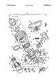
- FIG. 1is an exploded view of a preferred embodiment of the clamping assembly according to the present invention with portions shown in cross section for clarity.
- a housing 12includes slots 13 and 14 for hanging the clamping assembly 10 on the rail of a medical table not shown.
- rails of medical tables or chairsare substantially rectangular and mounted to the table so their width is narrower than their height.
- slot 13is placed over the width of the rail and the height of the rail is situated within slot 14.
- the arrangement of slots 13, 14could be modified to accommodate the structure to which the clamping assembly 10 is to be attached.
- the housing 12is preferably a unitary construction made of T6061 aluminum, but other suitable materials could be used.
- Means for releasably securing the clamping assembly 10 to a railis integrated with the housing 12. This means includes a first aperture 15 within said housing 12 into which a locking lug 16 is inserted. Additionally, means is provided for engaging said locking lug 16 against the rail of a medical table so that the clamping assembly 10 is rigidly held in place.
- Means for engaging the locking lug 16 against the railincludes a first leg 18 and a second leg 20 each extending in a substantially perpendicular manner from a bottom ledge 22 of slot 14.
- First leg 18includes a second aperture 24 and second leg 20 includes a third aperture 26; apertures 24, 26 being used to rotationally support a cam handle 28.
- second aperture 24is about 0.375 inches and third aperture 26 is about 0.5625 inches in inside diameter.
- the cam handle 28includes a distal shaft portion 29, a proximal shaft portion 30, and a center portion 32. Shaft portions 29, 30 have suitable diameters so that cam handle 28 is rotatably supported within apertures 24, 26. A set screw 33 is used to secure a camming member 34 to the center portion 32 after the cam handle 28 has been inserted through the apertures 22, 24.
- the locking lug 16is inserted within the first aperture 15 prior to the cam handle 28 being inserted through the apertures 22, 24.
- the camming member 34includes a camming surface 40 that cammingly engages the locking lug 16 when the cam handle 28 is rotated about its longitudinal axis thereby urging the locking lug 16 against the rail of the medical table. Rotating the cam handle 28 in the opposite direction releases the locking lug 16 from the rail.
- Locking lug 16preferably includes stepped portions 37 to accommodate rails having different heights. Alternatively, the locking lug 16 could include one step or be completely flat to accomodate the rail configuration.
- Camming member 34is preferably cylindrical with a longitudinal groove 35 for interlocking the camming member 34 with the center portion 32 of the cam handle 28.
- a rotatable shaft 42is inserted through a fourth aperture 44 in the housing 12.
- the shaft 42preferably has a length of about 3,625 inches and is made of stainless steel type 300.
- a recess 46is formed in the housing 12 that cooperates with a flange 48 on the shaft 42 to prevent unwanted axial displacement of the shaft 42.
- the shaft 42includes a threaded portion 50 that terminates and forms a shoulder 52.
- the threaded portion 50is preferably of fine threads, about 0.875 inches in length and about 1.125 inches in outside diameter.
- a pair of diametrically opposed flat surfaces 51are located substantially on the threaded portion 50.
- a reduced diameter portion 54 of shaft 42extends from the shoulder 52 and forms the distal end 58 of the shaft 42.
- reduced diameter portionhas an outside diameter of about 1.00 inch.
- An aperture 56is formed within the reduced diameter portion 54 of the shaft 42 through which a support rod (not shown) for hanging medical accessories extends. Aperture 56 may be various shapes to accomodate different types of support rods.
- the distal end 58 of the shaft 42has an axial threaded shaft aperture 60 for receiving a handle 62 for adjusting the longitudinal displacement of the support rod which will be more fully described hereinafter.
- Means for rotationally adjusting the shaft 42 about its longitudinal axisincludes a toothed locking ring 64 disposed upon the shaft 42 in rotational engagement therewith.
- a toothed locking ring 64disposed upon the shaft 42 in rotational engagement therewith.
- a plurality of teeth 66are circumferentially disposed on the housing 12 around the fourth aperture 44 that interact with the toothed locking ring 64.
- toothed locking ring 64When the toothed locking ring 64 is in a second position it is sufficiently spaced from teeth 66 so that the toothed locking ring 64, shaft 42, and the support rod may be rotated relative to the housing. Means is provided for moving the toothed locking ring 64 between the first position and the second position.
- the locking nut 70includes a recessed cavity 72 for receiving the toothed locking ring 64.
- the washer 68is placed within the cavity 72 so it is between the shoulder 74 and the toothed locking ring 64 to reduce the rotational friction exerted against the toothed locking ring 64 when the locking nut 70 is tightened.
- the compression spring 68is captured between a recess 76 of the housing 12 and a recess 78 formed on the toothed locking ring 64.
- the plurality of circumferentially disposed teeth 66interact with a plurality of teeth 82 disposed on the toothed locking ring 64.
- Each tooth 66, 82preferably forms an included angle of about 60° and has a base that forms an arc of about 9°.
- the locking nut 70includes an internally threaded aperture 84 that cooperates with the threaded portion 50 of the shaft 42.
- the exterior surface of locking nut 70has longitudinal grooves to provide a suitable gripping surface for rotational purposes.
- the toothed locking ring 64includes a pair of diametrically opposed flat surfaces 86 that align with the surfaces 51 so that the shaft 42 and the toothed locking ring 64 are locked in rotational engagement.
- the compression spring 68urges the toothed locking ring 64 away from the housing 12 so that the toothed locking ring 64 and the shaft 42 may be rotated about the shaft's 42 longitudinal axis.
- the rotation of the shaft 42may be incrementally metered by the interaction of the teeth 66, 82, i.e., when locking nut 70 is sufficiently loosened teeth 66, 82 are still slightly engaged but they are loose enough to allow the toothed locking ring 64 to be axially translated and simultaneously rotated.
- Meansis provided for regulating the longitudinal displacement of the support rod within aperture 56 of the shaft 42.
- This meansincludes a proximal rod locking ring 88 and a distal rod locking ring 90.
- the proximal rod locking ring 88abuts the shoulder 52.
- the proximal and distal rod locking rings 88, 90are secured to the shaft 42 in any conventional manner such as by allen screws.
- Each ring 88, 90includes a diametric notch 92, 93 respectively.
- the locking rings 88, 90are situated on the shaft 42 so that locking ring 88 is on one side of aperture 56 and locking ring 90 is on the other side of aperture 56 with the support rod situated within aperture 56 between the notches 92, 93.
- the notch 92 of ring 88is substantially V-shaped so the support rod may be urged into the V and maintained in position. Notch 92 may be other shapes to accomodate the shape of the support rod if necessary. Means is provided for urging the support rod into the V-shaped notch 92.
- the means for urging the support rod into the notch 92 of ring 88includes a handle 62 that is preferably triangular.
- the handle 62includes a threaded stem 94 that cooperates with the threaded shaft aperture 60.
- the threaded stem 94is sufficiently long to extend into the aperture 56 of shaft 42.
- the stem 94engages the support rod and urges it toward the notch 92.
- the diameter of the support rodis sufficiently large so that it is captured between the notch 92 and the stem 94 when handle 62 is tightened.
- Handle 62is preferably shaped triangularly for easy manipulation by the user.
- a fifth aperture 98is disposed within the housing 12 and has internal threads.
- a spring pin 100, bevel washers 102, and a tensioner 104are inserted within the fifth aperture 98 so that the spring pin 100 abuts the top of the rail or track.
- Tensioner 104is externally threaded to cooperate with the internal threads of aperture 98.
- tensioner 104is tightened the spring pin 100 is urged against the rail by the compression of the bevel washers.
- An identical arrangement (not shown)is provided in a sixth aperture (not shown) on the opposite side of the housing. When tensioner 104 is loosened, the spring pin 100 has no tension on the rail or other fixture.
Landscapes
- Engineering & Computer Science (AREA)
- Health & Medical Sciences (AREA)
- Mechanical Engineering (AREA)
- General Engineering & Computer Science (AREA)
- Biomedical Technology (AREA)
- Life Sciences & Earth Sciences (AREA)
- Animal Behavior & Ethology (AREA)
- General Health & Medical Sciences (AREA)
- Public Health (AREA)
- Veterinary Medicine (AREA)
- Accommodation For Nursing Or Treatment Tables (AREA)
Abstract
Description
Claims (16)
Priority Applications (1)
| Application Number | Priority Date | Filing Date | Title |
|---|---|---|---|
| US07/673,942US5108213A (en) | 1991-03-22 | 1991-03-22 | Clamping assembly |
Applications Claiming Priority (1)
| Application Number | Priority Date | Filing Date | Title |
|---|---|---|---|
| US07/673,942US5108213A (en) | 1991-03-22 | 1991-03-22 | Clamping assembly |
Publications (1)
| Publication Number | Publication Date |
|---|---|
| US5108213Atrue US5108213A (en) | 1992-04-28 |
Family
ID=24704708
Family Applications (1)
| Application Number | Title | Priority Date | Filing Date |
|---|---|---|---|
| US07/673,942Expired - LifetimeUS5108213A (en) | 1991-03-22 | 1991-03-22 | Clamping assembly |
Country Status (1)
| Country | Link |
|---|---|
| US (1) | US5108213A (en) |
Cited By (30)
| Publication number | Priority date | Publication date | Assignee | Title |
|---|---|---|---|---|
| US5269034A (en)* | 1992-12-22 | 1993-12-14 | Ohio Medical Instrument Company, Inc. | Surgical head clamp |
| US5538215A (en)* | 1994-11-15 | 1996-07-23 | Midmark Corporation | Siderail socket |
| US6691350B2 (en) | 1999-12-13 | 2004-02-17 | Hill-Rom Services, Inc. | Accessories for a patient support apparatus |
| US20060255220A1 (en)* | 2004-11-10 | 2006-11-16 | Skripps Thomas K | Accessory rail clamp with latch and lock mechanisms |
| US20060278785A1 (en)* | 2005-05-26 | 2006-12-14 | Sherwood Services Ag | Flexible clamping apparatus for medical devices |
| US20070011814A1 (en)* | 2005-07-14 | 2007-01-18 | Jeremy Rotert | Surgical table attachment |
| US20080077078A1 (en)* | 2006-09-19 | 2008-03-27 | Locke Christopher B | Hanging apparatus for fixing a medical device to a substantially horizontal or substantially vertical support structure |
| US20080272254A1 (en)* | 2007-05-04 | 2008-11-06 | Tyco Healthcare Group Lp | Medical Device Safety Support with Infinite Positioning |
| US20090125055A1 (en)* | 2007-11-08 | 2009-05-14 | Tyco Healthcare Group Lp | Telescopingly adjustable clamp |
| US7546993B1 (en) | 2008-03-25 | 2009-06-16 | Tyco Healthcare Group Lp | Flexible clamping apparatus for medical devices |
| US20100065700A1 (en)* | 2007-01-20 | 2010-03-18 | Fresenius Vial Sas | Lock for fixation device |
| US20100189578A1 (en)* | 2009-01-26 | 2010-07-29 | Tyco Healthcare Group Lp | Mount for a compression control unit |
| US20110119829A1 (en)* | 2007-08-24 | 2011-05-26 | ALLEN MEDICAL SYSTEMS ,INC. a corporation | Surgical table accessory platform |
| RU2423642C2 (en)* | 2006-09-19 | 2011-07-10 | КейСиАй Лайсензинг Инк. | Suspension device to fix medical device to horizontal or to vertical support structure |
| USD659839S1 (en) | 2010-08-16 | 2012-05-15 | Tyco Healthcare Group Lp | Support for a pneumatic compression controller |
| USD675741S1 (en) | 2010-08-16 | 2013-02-05 | Covidien Lp | Pneumatic compression controller |
| US20130175264A1 (en)* | 2012-01-06 | 2013-07-11 | Wistron Corporation | Hinge Mechanism and Clamshell Device Thereof |
| CN103462769A (en)* | 2013-09-03 | 2013-12-25 | 苏州柯尔医疗器械有限公司 | Guide rail and check block mechanism of surgical bed |
| US8833707B2 (en) | 2010-07-15 | 2014-09-16 | Allen Medical Systems, Inc. | Disposable urology drainage bag |
| CN104121277A (en)* | 2013-04-24 | 2014-10-29 | 加藤电机(香港)有限公司 | Hinge device with latch mechanism and intelligence machine |
| US9161875B2 (en) | 2012-09-07 | 2015-10-20 | Allen Medical Systems, Inc. | Multi-axis joint for a spar of a limb holder |
| US9498397B2 (en) | 2012-04-16 | 2016-11-22 | Allen Medical Systems, Inc. | Dual column surgical support system |
| US9655793B2 (en) | 2015-04-09 | 2017-05-23 | Allen Medical Systems, Inc. | Brake release mechanism for surgical table |
| CN108119738A (en)* | 2018-02-01 | 2018-06-05 | 合肥雅观匠道科技有限公司 | Air purifier self-locking and method for dismounting based on net cluster ion technology |
| US10188573B2 (en) | 2014-11-05 | 2019-01-29 | Allen Medical Systems, Inc. | Boot stirrup |
| EP3673860A1 (en)* | 2018-12-31 | 2020-07-01 | Biosense Webster (Israel) Ltd. | Mounting device for medical equipment |
| US10765592B2 (en) | 2006-09-19 | 2020-09-08 | Kci Licensing, Inc. | System and method for determining a fill status of a canister of fluid in a reduced pressure treatment system |
| US10806835B2 (en) | 2006-09-19 | 2020-10-20 | Kci Licensing, Inc. | Reduced pressure treatment system having blockage clearing and dual-zone pressure protection capabilities |
| US11202731B2 (en) | 2018-02-28 | 2021-12-21 | Allen Medical Systems, Inc. | Surgical patient support and methods thereof |
| US11213448B2 (en) | 2017-07-31 | 2022-01-04 | Allen Medical Systems, Inc. | Rotation lockout for surgical support |
Citations (6)
| Publication number | Priority date | Publication date | Assignee | Title |
|---|---|---|---|---|
| US3339913A (en)* | 1963-10-08 | 1967-09-05 | Ritter Pfaudler Corp | Accessory clamping structure for surgical tables |
| US3357726A (en)* | 1966-11-10 | 1967-12-12 | Theodore C Gabrielson | Clamping device |
| US4018412A (en)* | 1975-10-14 | 1977-04-19 | Kees Surgical Specialty Company | Bracket for an operating table |
| US4547092A (en)* | 1984-02-21 | 1985-10-15 | Hamilton Industries | Accessory clamp for medical table |
| US4747569A (en)* | 1987-07-13 | 1988-05-31 | Hoshino Gakki Co., Ltd. | Support head for a musical instrument holder or the like |
| US4865484A (en)* | 1987-07-31 | 1989-09-12 | Mcconnell Thomas E | Single release, multiple axis coupling |
- 1991
- 1991-03-22USUS07/673,942patent/US5108213A/ennot_activeExpired - Lifetime
Patent Citations (6)
| Publication number | Priority date | Publication date | Assignee | Title |
|---|---|---|---|---|
| US3339913A (en)* | 1963-10-08 | 1967-09-05 | Ritter Pfaudler Corp | Accessory clamping structure for surgical tables |
| US3357726A (en)* | 1966-11-10 | 1967-12-12 | Theodore C Gabrielson | Clamping device |
| US4018412A (en)* | 1975-10-14 | 1977-04-19 | Kees Surgical Specialty Company | Bracket for an operating table |
| US4547092A (en)* | 1984-02-21 | 1985-10-15 | Hamilton Industries | Accessory clamp for medical table |
| US4747569A (en)* | 1987-07-13 | 1988-05-31 | Hoshino Gakki Co., Ltd. | Support head for a musical instrument holder or the like |
| US4865484A (en)* | 1987-07-31 | 1989-09-12 | Mcconnell Thomas E | Single release, multiple axis coupling |
Cited By (65)
| Publication number | Priority date | Publication date | Assignee | Title |
|---|---|---|---|---|
| US5269034A (en)* | 1992-12-22 | 1993-12-14 | Ohio Medical Instrument Company, Inc. | Surgical head clamp |
| US5538215A (en)* | 1994-11-15 | 1996-07-23 | Midmark Corporation | Siderail socket |
| US6691350B2 (en) | 1999-12-13 | 2004-02-17 | Hill-Rom Services, Inc. | Accessories for a patient support apparatus |
| US20040068798A1 (en)* | 1999-12-13 | 2004-04-15 | Weismiller Matthew W. | Accessories for a patient support apparatus |
| US6948202B2 (en) | 1999-12-13 | 2005-09-27 | Hill-Rom Services, Inc. | Accessories for a patient support apparatus |
| US20060016010A1 (en)* | 1999-12-13 | 2006-01-26 | Hill-Rom Services, Inc. | Accessories for a patient support apparatus |
| US7171709B2 (en) | 1999-12-13 | 2007-02-06 | Hill-Rom Services, Inc. | Accessories for a patient support apparatus |
| US20060255220A1 (en)* | 2004-11-10 | 2006-11-16 | Skripps Thomas K | Accessory rail clamp with latch and lock mechanisms |
| US7520007B2 (en) | 2004-11-10 | 2009-04-21 | Allen Medical Systems, Inc. | Accessory rail clamp with latch and lock mechanisms |
| US20060278785A1 (en)* | 2005-05-26 | 2006-12-14 | Sherwood Services Ag | Flexible clamping apparatus for medical devices |
| US7731138B2 (en) | 2005-05-26 | 2010-06-08 | Covidien Ag | Flexible clamping apparatus for medical devices |
| US20070011814A1 (en)* | 2005-07-14 | 2007-01-18 | Jeremy Rotert | Surgical table attachment |
| US20080077078A1 (en)* | 2006-09-19 | 2008-03-27 | Locke Christopher B | Hanging apparatus for fixing a medical device to a substantially horizontal or substantially vertical support structure |
| WO2008036344A1 (en)* | 2006-09-19 | 2008-03-27 | Kci Licensing Inc. | Hanging apparatus for fixing a medical device to a substantially horizontal or substantially vertical support structure |
| US10765592B2 (en) | 2006-09-19 | 2020-09-08 | Kci Licensing, Inc. | System and method for determining a fill status of a canister of fluid in a reduced pressure treatment system |
| US10806835B2 (en) | 2006-09-19 | 2020-10-20 | Kci Licensing, Inc. | Reduced pressure treatment system having blockage clearing and dual-zone pressure protection capabilities |
| US8096515B2 (en) | 2006-09-19 | 2012-01-17 | Kci Licensing, Inc. | Hanging apparatus for fixing a medical device to a substantially horizontal or substantially vertical support structure |
| RU2423642C2 (en)* | 2006-09-19 | 2011-07-10 | КейСиАй Лайсензинг Инк. | Suspension device to fix medical device to horizontal or to vertical support structure |
| US11229732B2 (en) | 2006-09-19 | 2022-01-25 | Kci Licensing, Inc. | System and method for locating fluid leaks at a drape of a reduced pressure delivery system |
| US7770855B2 (en) | 2006-09-19 | 2010-08-10 | Kci Licensing, Inc | Hanging apparatus for fixing a medical device to a substantially horizontal or substantially vertical support structure |
| US20100276556A1 (en)* | 2006-09-19 | 2010-11-04 | Christopher Brian Locke | Hanging apparatus for fixing a medical device to a substantially horizontal or substantially vertical support structure |
| CN101517305B (en)* | 2006-09-19 | 2010-12-29 | 凯希特许有限公司 | Hanging apparatus for fixing a medical device to a substantially horizontal or substantially vertical support structure |
| AU2007297655B2 (en)* | 2006-09-19 | 2011-10-27 | 3M Innovative Properties Company | Hanging apparatus for fixing a medical device to a substantially horizontal or substantially vertical support structure |
| US20100065700A1 (en)* | 2007-01-20 | 2010-03-18 | Fresenius Vial Sas | Lock for fixation device |
| US8047482B2 (en)* | 2007-01-20 | 2011-11-01 | Fresenius Vial Sas | Lock for fixation device |
| US7980521B2 (en) | 2007-05-04 | 2011-07-19 | Tyco Healthcare Group Lp | Medical device safety support with infinite positioning |
| US20080272254A1 (en)* | 2007-05-04 | 2008-11-06 | Tyco Healthcare Group Lp | Medical Device Safety Support with Infinite Positioning |
| US20110119829A1 (en)* | 2007-08-24 | 2011-05-26 | ALLEN MEDICAL SYSTEMS ,INC. a corporation | Surgical table accessory platform |
| US8397323B2 (en) | 2007-08-24 | 2013-03-19 | Allen Medical Systems, Inc. | Surgical table accessory platform |
| US20090125055A1 (en)* | 2007-11-08 | 2009-05-14 | Tyco Healthcare Group Lp | Telescopingly adjustable clamp |
| US8246028B2 (en) | 2007-11-08 | 2012-08-21 | Tyco Healthcare Group Lp | Telescopingly adjustable clamp |
| US7546993B1 (en) | 2008-03-25 | 2009-06-16 | Tyco Healthcare Group Lp | Flexible clamping apparatus for medical devices |
| US8414272B2 (en) | 2009-01-26 | 2013-04-09 | Covidien Lp | Mount for a compression control unit |
| US20100189578A1 (en)* | 2009-01-26 | 2010-07-29 | Tyco Healthcare Group Lp | Mount for a compression control unit |
| US8133039B2 (en) | 2009-01-26 | 2012-03-13 | Tyco Healthcare Group Lp | Mount for a compression control unit |
| US8833707B2 (en) | 2010-07-15 | 2014-09-16 | Allen Medical Systems, Inc. | Disposable urology drainage bag |
| USD659839S1 (en) | 2010-08-16 | 2012-05-15 | Tyco Healthcare Group Lp | Support for a pneumatic compression controller |
| USD675741S1 (en) | 2010-08-16 | 2013-02-05 | Covidien Lp | Pneumatic compression controller |
| US20130175264A1 (en)* | 2012-01-06 | 2013-07-11 | Wistron Corporation | Hinge Mechanism and Clamshell Device Thereof |
| US8584320B2 (en)* | 2012-01-06 | 2013-11-19 | Wistron Corporation | Hinge mechanism and clamshell device thereof |
| US11452657B2 (en) | 2012-04-16 | 2022-09-27 | Allen Medical Systems, Inc. | Dual column surgical table having a single-handle unlock for table rotation |
| US10993864B2 (en) | 2012-04-16 | 2021-05-04 | Allen Medical Systems, Inc. | Bracket attachment apparatus for dual column surgical table |
| US9968503B2 (en) | 2012-04-16 | 2018-05-15 | Allen Medical Systems, Inc. | Dual column surgical table having a single-handle unlock for table rotation |
| US12186242B2 (en) | 2012-04-16 | 2025-01-07 | Allen Medical Systems, Inc. | Dual column surgical table having a single-handle unlock for table rotation |
| US11938065B2 (en) | 2012-04-16 | 2024-03-26 | Allen Medical Systems, Inc. | Table top to bracket coupling apparatus for spine surgery table |
| US9498397B2 (en) | 2012-04-16 | 2016-11-22 | Allen Medical Systems, Inc. | Dual column surgical support system |
| US10238568B2 (en) | 2012-09-07 | 2019-03-26 | Allen Medical Systems, Inc. | Release handle mechanisms for a spar of a limb holder |
| US10398615B2 (en) | 2012-09-07 | 2019-09-03 | Allen Medical Systems, Inc. | Multi-axis joint for a spar of a limb holder |
| US9161875B2 (en) | 2012-09-07 | 2015-10-20 | Allen Medical Systems, Inc. | Multi-axis joint for a spar of a limb holder |
| CN104121277A (en)* | 2013-04-24 | 2014-10-29 | 加藤电机(香港)有限公司 | Hinge device with latch mechanism and intelligence machine |
| CN103462769A (en)* | 2013-09-03 | 2013-12-25 | 苏州柯尔医疗器械有限公司 | Guide rail and check block mechanism of surgical bed |
| US10188573B2 (en) | 2014-11-05 | 2019-01-29 | Allen Medical Systems, Inc. | Boot stirrup |
| US11147730B2 (en) | 2014-11-05 | 2021-10-19 | Allen Medical Systems, Inc. | Boot stirrup having adjustable length boot |
| US12102571B2 (en) | 2014-11-05 | 2024-10-01 | Allen Medical Systems, Inc. | Releasable spar for surgical boot |
| US9655793B2 (en) | 2015-04-09 | 2017-05-23 | Allen Medical Systems, Inc. | Brake release mechanism for surgical table |
| US11752055B2 (en) | 2017-07-31 | 2023-09-12 | Allen Medical Systems, Inc. | Rotation lockout for surgical support |
| US11213448B2 (en) | 2017-07-31 | 2022-01-04 | Allen Medical Systems, Inc. | Rotation lockout for surgical support |
| US11554068B2 (en) | 2017-07-31 | 2023-01-17 | Allen Medical Systems, Inc. | Rotation lockout for surgical support |
| US12029689B2 (en) | 2017-07-31 | 2024-07-09 | Allen Medical Systems, Inc. | Controls for surgical support apparatus |
| CN108119738B (en)* | 2018-02-01 | 2019-10-08 | 浙江亨达塑料模具有限公司 | Air purifier based on net cluster ion technology is self-locking and method for dismounting |
| CN108119738A (en)* | 2018-02-01 | 2018-06-05 | 合肥雅观匠道科技有限公司 | Air purifier self-locking and method for dismounting based on net cluster ion technology |
| US11202731B2 (en) | 2018-02-28 | 2021-12-21 | Allen Medical Systems, Inc. | Surgical patient support and methods thereof |
| US12220359B2 (en) | 2018-02-28 | 2025-02-11 | Allen Medical Systems, Inc. | Surgical patient support and methods thereof |
| US11033355B2 (en) | 2018-12-31 | 2021-06-15 | Biosense Webster (Israel) Ltd. | Mounting device for medical equipment |
| EP3673860A1 (en)* | 2018-12-31 | 2020-07-01 | Biosense Webster (Israel) Ltd. | Mounting device for medical equipment |
Similar Documents
| Publication | Publication Date | Title |
|---|---|---|
| US5108213A (en) | Clamping assembly | |
| US4547092A (en) | Accessory clamp for medical table | |
| US5369827A (en) | Medical stirrups | |
| US5582379A (en) | Adjustable limb support system | |
| US5020195A (en) | Clamping device for use on a retractor support | |
| US4832299A (en) | Clamp fixture | |
| US5284129A (en) | Swivel ring surgical retractor | |
| US5792046A (en) | Cammed retractor clamp | |
| US7232411B2 (en) | Radiolucent retractor and related components | |
| US4865484A (en) | Single release, multiple axis coupling | |
| US5560577A (en) | Adjustable limb support system | |
| US7611460B2 (en) | Surgical support arm docking apparatus | |
| US5263956A (en) | Ball joint for neurosurgery | |
| US7857271B2 (en) | Surgical tool holder with engagement portions | |
| US5902233A (en) | Angling surgical retractor apparatus and method of retracting anatomy | |
| US4708510A (en) | Ball joint coupling | |
| US6708935B2 (en) | Device for upper extremity elevation | |
| EP3116462B1 (en) | Limb positioning system | |
| EP1366714A2 (en) | Accessory clamping system for couch top | |
| JPH1156872A (en) | Outer miniaturized splint device | |
| EP0397737A4 (en) | Retractor apparatus | |
| US20100242177A1 (en) | Padded patient immobilizer for surgery tables | |
| WO1994014386A1 (en) | Surgical head clamp | |
| US4964748A (en) | Positioning device | |
| US6042541A (en) | Clamping device for a surgical retractor |
Legal Events
| Date | Code | Title | Description |
|---|---|---|---|
| AS | Assignment | Owner name:EDGEWATER MEDICAL EQUIPMENT SYSTEMS, INC., A CORP. Free format text:ASSIGNMENT OF ASSIGNORS INTEREST.;ASSIGNOR:SHIELDS, JOHN;REEL/FRAME:005653/0665 Effective date:19910320 | |
| FEPP | Fee payment procedure | Free format text:PAYOR NUMBER ASSIGNED (ORIGINAL EVENT CODE: ASPN); ENTITY STATUS OF PATENT OWNER: LARGE ENTITY | |
| STCF | Information on status: patent grant | Free format text:PATENTED CASE | |
| AS | Assignment | Owner name:STAR BANK, N.A., OHIO Free format text:MORTGAGE;ASSIGNOR:EDGEWATER MEDICAL EQUIPMENT SYSTEMS, INC. D/B/A ALLEN MEDICAL SYSTEMS;REEL/FRAME:006761/0030 Effective date:19930429 | |
| FPAY | Fee payment | Year of fee payment:4 | |
| FEPP | Fee payment procedure | Free format text:PAT HLDR NO LONGER CLAIMS SMALL ENT STAT AS SMALL BUSINESS (ORIGINAL EVENT CODE: LSM2); ENTITY STATUS OF PATENT OWNER: LARGE ENTITY | |
| AS | Assignment | Owner name:AMATECH CORPORATION, MASSACHUSETTS Free format text:ASSIGNMENT OF ASSIGNORS INTEREST;ASSIGNOR:ALLEN MEDICAL SYSTEMS, INC.;REEL/FRAME:009703/0021 Effective date:19981201 | |
| AS | Assignment | Owner name:AMATECH CORPORATION, MASSACHUSETTS Free format text:ASSIGNMENT OF ASSIGNORS INTEREST;ASSIGNOR:ALLEN MEDICAL SYSTEMS, INC.;REEL/FRAME:009689/0808 Effective date:19990107 | |
| AS | Assignment | Owner name:STATE STREET BANK AND TRUST COMPANY, MASSACHUSETTS Free format text:SECURITY INTEREST;ASSIGNOR:AMATECH CORPORATION;REEL/FRAME:009693/0560 Effective date:19981201 | |
| AS | Assignment | Owner name:OUTSIDE, INC., INDIANA Free format text:ASSIGNMENT OF ASSIGNORS INTEREST;ASSIGNOR:SG TRUSTEE LLC;REEL/FRAME:010188/0724 Effective date:19990518 | |
| FPAY | Fee payment | Year of fee payment:8 | |
| AS | Assignment | Owner name:AMATECH CORPORATION, INDIANA Free format text:CHANGE OF NAME;ASSIGNOR:OUTSIDE, INC.;REEL/FRAME:010579/0389 Effective date:19990802 Owner name:OR GROUP, INC., THE, INDIANA Free format text:CHANGE OF NAME;ASSIGNOR:AMATECH CORPORATION;REEL/FRAME:010579/0394 Effective date:19991129 | |
| AS | Assignment | Owner name:OR GROUP INC.,THE, INDIANA Free format text:CHANGE OF NAME;ASSIGNOR:OUTSIDE INC.;REEL/FRAME:011284/0679 Effective date:19990802 | |
| FPAY | Fee payment | Year of fee payment:12 | |
| FEPP | Fee payment procedure | Free format text:PAYER NUMBER DE-ASSIGNED (ORIGINAL EVENT CODE: RMPN); ENTITY STATUS OF PATENT OWNER: LARGE ENTITY Free format text:PAYOR NUMBER ASSIGNED (ORIGINAL EVENT CODE: ASPN); ENTITY STATUS OF PATENT OWNER: LARGE ENTITY |