US5107276A - Thermal ink jet printhead with constant operating temperature - Google Patents
Thermal ink jet printhead with constant operating temperatureDownload PDFInfo
- Publication number
- US5107276A US5107276AUS07/572,075US57207590AUS5107276AUS 5107276 AUS5107276 AUS 5107276AUS 57207590 AUS57207590 AUS 57207590AUS 5107276 AUS5107276 AUS 5107276A
- Authority
- US
- United States
- Prior art keywords
- printhead
- pulses
- heating elements
- ink
- droplet ejecting
- Prior art date
- Legal status (The legal status is an assumption and is not a legal conclusion. Google has not performed a legal analysis and makes no representation as to the accuracy of the status listed.)
- Expired - Lifetime
Links
- 238000010438heat treatmentMethods0.000claimsabstractdescription126
- 238000007639printingMethods0.000claimsabstractdescription79
- 230000004044responseEffects0.000claimsabstractdescription6
- 238000000034methodMethods0.000claimsdescription21
- 230000000153supplemental effectEffects0.000claimsdescription18
- 230000000694effectsEffects0.000claimsdescription2
- 230000006872improvementEffects0.000claimsdescription2
- 230000000737periodic effectEffects0.000claims3
- 238000012935AveragingMethods0.000claims1
- 230000017525heat dissipationEffects0.000claims1
- 238000011144upstream manufacturingMethods0.000abstract1
- 239000000976inkSubstances0.000description85
- VYPSYNLAJGMNEJ-UHFFFAOYSA-NSilicium dioxideChemical compoundO=[Si]=OVYPSYNLAJGMNEJ-UHFFFAOYSA-N0.000description12
- 239000000758substrateSubstances0.000description11
- 238000002161passivationMethods0.000description9
- 235000012431wafersNutrition0.000description9
- 239000000463materialSubstances0.000description8
- 235000012239silicon dioxideNutrition0.000description6
- 239000000377silicon dioxideSubstances0.000description6
- 230000000295complement effectEffects0.000description5
- 229910052581Si3N4Inorganic materials0.000description4
- 230000008901benefitEffects0.000description4
- 238000005229chemical vapour depositionMethods0.000description4
- 229910021420polycrystalline siliconInorganic materials0.000description4
- HQVNEWCFYHHQES-UHFFFAOYSA-Nsilicon nitrideChemical compoundN12[Si]34N5[Si]62N3[Si]51N64HQVNEWCFYHHQES-UHFFFAOYSA-N0.000description4
- LYCAIKOWRPUZTN-UHFFFAOYSA-NEthylene glycolChemical compoundOCCOLYCAIKOWRPUZTN-UHFFFAOYSA-N0.000description3
- XUIMIQQOPSSXEZ-UHFFFAOYSA-NSiliconChemical compound[Si]XUIMIQQOPSSXEZ-UHFFFAOYSA-N0.000description3
- 238000013459approachMethods0.000description3
- 230000004888barrier functionEffects0.000description3
- 238000007641inkjet printingMethods0.000description3
- 229920005591polysiliconPolymers0.000description3
- 229910052710siliconInorganic materials0.000description3
- 239000010703siliconSubstances0.000description3
- XLYOFNOQVPJJNP-UHFFFAOYSA-NwaterSubstancesOXLYOFNOQVPJJNP-UHFFFAOYSA-N0.000description3
- 239000004642PolyimideSubstances0.000description2
- QCWXUUIWCKQGHC-UHFFFAOYSA-NZirconiumChemical compound[Zr]QCWXUUIWCKQGHC-UHFFFAOYSA-N0.000description2
- 230000009471actionEffects0.000description2
- XAGFODPZIPBFFR-UHFFFAOYSA-NaluminiumChemical compound[Al]XAGFODPZIPBFFR-UHFFFAOYSA-N0.000description2
- 229910052782aluminiumInorganic materials0.000description2
- 230000007423decreaseEffects0.000description2
- 238000010586diagramMethods0.000description2
- 238000005530etchingMethods0.000description2
- 238000009472formulationMethods0.000description2
- 230000006870functionEffects0.000description2
- BHEPBYXIRTUNPN-UHFFFAOYSA-Nhydridophosphorus(.) (triplet)Chemical compound[PH]BHEPBYXIRTUNPN-UHFFFAOYSA-N0.000description2
- 238000012423maintenanceMethods0.000description2
- 230000005499meniscusEffects0.000description2
- 239000000203mixtureSubstances0.000description2
- 238000012986modificationMethods0.000description2
- 230000004048modificationEffects0.000description2
- 150000004767nitridesChemical class0.000description2
- 230000006911nucleationEffects0.000description2
- 238000010899nucleationMethods0.000description2
- 238000004806packaging method and processMethods0.000description2
- 229920001721polyimidePolymers0.000description2
- 238000013519translationMethods0.000description2
- 229910052726zirconiumInorganic materials0.000description2
- 108010032039(rat secretin-27)-Gly-rhodamineProteins0.000description1
- 229910007277Si3 N4Inorganic materials0.000description1
- LRTTZMZPZHBOPO-UHFFFAOYSA-N[B].[B].[Hf]Chemical compound[B].[B].[Hf]LRTTZMZPZHBOPO-UHFFFAOYSA-N0.000description1
- 239000002250absorbentSubstances0.000description1
- 230000002745absorbentEffects0.000description1
- 230000001133accelerationEffects0.000description1
- 238000009825accumulationMethods0.000description1
- 230000015572biosynthetic processEffects0.000description1
- 230000015556catabolic processEffects0.000description1
- BGTFCAQCKWKTRL-YDEUACAXSA-Nchembl1095986Chemical compoundC1[C@@H](N)[C@@H](O)[C@H](C)O[C@H]1O[C@@H]([C@H]1C(N[C@H](C2=CC(O)=CC(O[C@@H]3[C@H]([C@@H](O)[C@H](O)[C@@H](CO)O3)O)=C2C=2C(O)=CC=C(C=2)[C@@H](NC(=O)[C@@H]2NC(=O)[C@@H]3C=4C=C(C(=C(O)C=4)C)OC=4C(O)=CC=C(C=4)[C@@H](N)C(=O)N[C@@H](C(=O)N3)[C@H](O)C=3C=CC(O4)=CC=3)C(=O)N1)C(O)=O)=O)C(C=C1)=CC=C1OC1=C(O[C@@H]3[C@H]([C@H](O)[C@@H](O)[C@H](CO[C@@H]5[C@H]([C@@H](O)[C@H](O)[C@@H](C)O5)O)O3)O[C@@H]3[C@H]([C@@H](O)[C@H](O)[C@@H](CO)O3)O[C@@H]3[C@H]([C@H](O)[C@@H](CO)O3)O)C4=CC2=C1BGTFCAQCKWKTRL-YDEUACAXSA-N0.000description1
- 239000003086colorantSubstances0.000description1
- 230000008602contractionEffects0.000description1
- 230000003247decreasing effectEffects0.000description1
- 230000007547defectEffects0.000description1
- 238000006731degradation reactionMethods0.000description1
- 230000003111delayed effectEffects0.000description1
- 238000000151depositionMethods0.000description1
- 230000008021depositionEffects0.000description1
- 238000013461designMethods0.000description1
- 238000001312dry etchingMethods0.000description1
- 238000005868electrolysis reactionMethods0.000description1
- JEIPFZHSYJVQDO-UHFFFAOYSA-Nferric oxideChemical compoundO=[Fe]O[Fe]=OJEIPFZHSYJVQDO-UHFFFAOYSA-N0.000description1
- 238000010304firingMethods0.000description1
- 230000037406food intakeEffects0.000description1
- 239000011521glassSubstances0.000description1
- 238000012544monitoring processMethods0.000description1
- 238000000059patterningMethods0.000description1
- 239000002243precursorSubstances0.000description1
- 230000037452primingEffects0.000description1
- 230000002441reversible effectEffects0.000description1
- 229910052715tantalumInorganic materials0.000description1
- GUVRBAGPIYLISA-UHFFFAOYSA-Ntantalum atomChemical compound[Ta]GUVRBAGPIYLISA-UHFFFAOYSA-N0.000description1
- 238000012360testing methodMethods0.000description1
- 238000012546transferMethods0.000description1
- 238000010023transfer printingMethods0.000description1
- 230000008016vaporizationEffects0.000description1
- 238000010792warmingMethods0.000description1
- 238000001039wet etchingMethods0.000description1
Images


Classifications
- B—PERFORMING OPERATIONS; TRANSPORTING
- B41—PRINTING; LINING MACHINES; TYPEWRITERS; STAMPS
- B41J—TYPEWRITERS; SELECTIVE PRINTING MECHANISMS, i.e. MECHANISMS PRINTING OTHERWISE THAN FROM A FORME; CORRECTION OF TYPOGRAPHICAL ERRORS
- B41J2/00—Typewriters or selective printing mechanisms characterised by the printing or marking process for which they are designed
- B41J2/005—Typewriters or selective printing mechanisms characterised by the printing or marking process for which they are designed characterised by bringing liquid or particles selectively into contact with a printing material
- B41J2/01—Ink jet
- B41J2/015—Ink jet characterised by the jet generation process
- B41J2/04—Ink jet characterised by the jet generation process generating single droplets or particles on demand
- B41J2/045—Ink jet characterised by the jet generation process generating single droplets or particles on demand by pressure, e.g. electromechanical transducers
- B41J2/04501—Control methods or devices therefor, e.g. driver circuits, control circuits
- B41J2/04563—Control methods or devices therefor, e.g. driver circuits, control circuits detecting head temperature; Ink temperature
- B—PERFORMING OPERATIONS; TRANSPORTING
- B41—PRINTING; LINING MACHINES; TYPEWRITERS; STAMPS
- B41J—TYPEWRITERS; SELECTIVE PRINTING MECHANISMS, i.e. MECHANISMS PRINTING OTHERWISE THAN FROM A FORME; CORRECTION OF TYPOGRAPHICAL ERRORS
- B41J2/00—Typewriters or selective printing mechanisms characterised by the printing or marking process for which they are designed
- B41J2/005—Typewriters or selective printing mechanisms characterised by the printing or marking process for which they are designed characterised by bringing liquid or particles selectively into contact with a printing material
- B41J2/01—Ink jet
- B41J2/015—Ink jet characterised by the jet generation process
- B41J2/04—Ink jet characterised by the jet generation process generating single droplets or particles on demand
- B41J2/045—Ink jet characterised by the jet generation process generating single droplets or particles on demand by pressure, e.g. electromechanical transducers
- B41J2/04501—Control methods or devices therefor, e.g. driver circuits, control circuits
- B41J2/0458—Control methods or devices therefor, e.g. driver circuits, control circuits controlling heads based on heating elements forming bubbles
- B—PERFORMING OPERATIONS; TRANSPORTING
- B41—PRINTING; LINING MACHINES; TYPEWRITERS; STAMPS
- B41J—TYPEWRITERS; SELECTIVE PRINTING MECHANISMS, i.e. MECHANISMS PRINTING OTHERWISE THAN FROM A FORME; CORRECTION OF TYPOGRAPHICAL ERRORS
- B41J2/00—Typewriters or selective printing mechanisms characterised by the printing or marking process for which they are designed
- B41J2/005—Typewriters or selective printing mechanisms characterised by the printing or marking process for which they are designed characterised by bringing liquid or particles selectively into contact with a printing material
- B41J2/01—Ink jet
- B41J2/07—Ink jet characterised by jet control
- B41J2/072—Ink jet characterised by jet control by thermal compensation
- B—PERFORMING OPERATIONS; TRANSPORTING
- B41—PRINTING; LINING MACHINES; TYPEWRITERS; STAMPS
- B41J—TYPEWRITERS; SELECTIVE PRINTING MECHANISMS, i.e. MECHANISMS PRINTING OTHERWISE THAN FROM A FORME; CORRECTION OF TYPOGRAPHICAL ERRORS
- B41J2/00—Typewriters or selective printing mechanisms characterised by the printing or marking process for which they are designed
- B41J2/005—Typewriters or selective printing mechanisms characterised by the printing or marking process for which they are designed characterised by bringing liquid or particles selectively into contact with a printing material
- B41J2/01—Ink jet
- B41J2/135—Nozzles
- B41J2/16—Production of nozzles
- B41J2/1601—Production of bubble jet print heads
- B41J2/1604—Production of bubble jet print heads of the edge shooter type
- B—PERFORMING OPERATIONS; TRANSPORTING
- B41—PRINTING; LINING MACHINES; TYPEWRITERS; STAMPS
- B41J—TYPEWRITERS; SELECTIVE PRINTING MECHANISMS, i.e. MECHANISMS PRINTING OTHERWISE THAN FROM A FORME; CORRECTION OF TYPOGRAPHICAL ERRORS
- B41J2/00—Typewriters or selective printing mechanisms characterised by the printing or marking process for which they are designed
- B41J2/005—Typewriters or selective printing mechanisms characterised by the printing or marking process for which they are designed characterised by bringing liquid or particles selectively into contact with a printing material
- B41J2/01—Ink jet
- B41J2/135—Nozzles
- B41J2/16—Production of nozzles
- B41J2/1621—Manufacturing processes
- B41J2/1623—Manufacturing processes bonding and adhesion
- B—PERFORMING OPERATIONS; TRANSPORTING
- B41—PRINTING; LINING MACHINES; TYPEWRITERS; STAMPS
- B41J—TYPEWRITERS; SELECTIVE PRINTING MECHANISMS, i.e. MECHANISMS PRINTING OTHERWISE THAN FROM A FORME; CORRECTION OF TYPOGRAPHICAL ERRORS
- B41J2/00—Typewriters or selective printing mechanisms characterised by the printing or marking process for which they are designed
- B41J2/005—Typewriters or selective printing mechanisms characterised by the printing or marking process for which they are designed characterised by bringing liquid or particles selectively into contact with a printing material
- B41J2/01—Ink jet
- B41J2/135—Nozzles
- B41J2/16—Production of nozzles
- B41J2/1621—Manufacturing processes
- B41J2/1626—Manufacturing processes etching
- B41J2/1628—Manufacturing processes etching dry etching
- B—PERFORMING OPERATIONS; TRANSPORTING
- B41—PRINTING; LINING MACHINES; TYPEWRITERS; STAMPS
- B41J—TYPEWRITERS; SELECTIVE PRINTING MECHANISMS, i.e. MECHANISMS PRINTING OTHERWISE THAN FROM A FORME; CORRECTION OF TYPOGRAPHICAL ERRORS
- B41J2/00—Typewriters or selective printing mechanisms characterised by the printing or marking process for which they are designed
- B41J2/005—Typewriters or selective printing mechanisms characterised by the printing or marking process for which they are designed characterised by bringing liquid or particles selectively into contact with a printing material
- B41J2/01—Ink jet
- B41J2/135—Nozzles
- B41J2/16—Production of nozzles
- B41J2/1621—Manufacturing processes
- B41J2/1626—Manufacturing processes etching
- B41J2/1629—Manufacturing processes etching wet etching
- B—PERFORMING OPERATIONS; TRANSPORTING
- B41—PRINTING; LINING MACHINES; TYPEWRITERS; STAMPS
- B41J—TYPEWRITERS; SELECTIVE PRINTING MECHANISMS, i.e. MECHANISMS PRINTING OTHERWISE THAN FROM A FORME; CORRECTION OF TYPOGRAPHICAL ERRORS
- B41J2/00—Typewriters or selective printing mechanisms characterised by the printing or marking process for which they are designed
- B41J2/005—Typewriters or selective printing mechanisms characterised by the printing or marking process for which they are designed characterised by bringing liquid or particles selectively into contact with a printing material
- B41J2/01—Ink jet
- B41J2/135—Nozzles
- B41J2/16—Production of nozzles
- B41J2/1621—Manufacturing processes
- B41J2/1631—Manufacturing processes photolithography
- B—PERFORMING OPERATIONS; TRANSPORTING
- B41—PRINTING; LINING MACHINES; TYPEWRITERS; STAMPS
- B41J—TYPEWRITERS; SELECTIVE PRINTING MECHANISMS, i.e. MECHANISMS PRINTING OTHERWISE THAN FROM A FORME; CORRECTION OF TYPOGRAPHICAL ERRORS
- B41J2/00—Typewriters or selective printing mechanisms characterised by the printing or marking process for which they are designed
- B41J2/005—Typewriters or selective printing mechanisms characterised by the printing or marking process for which they are designed characterised by bringing liquid or particles selectively into contact with a printing material
- B41J2/01—Ink jet
- B41J2/135—Nozzles
- B41J2/16—Production of nozzles
- B41J2/1621—Manufacturing processes
- B41J2/1635—Manufacturing processes dividing the wafer into individual chips
- B—PERFORMING OPERATIONS; TRANSPORTING
- B41—PRINTING; LINING MACHINES; TYPEWRITERS; STAMPS
- B41J—TYPEWRITERS; SELECTIVE PRINTING MECHANISMS, i.e. MECHANISMS PRINTING OTHERWISE THAN FROM A FORME; CORRECTION OF TYPOGRAPHICAL ERRORS
- B41J2/00—Typewriters or selective printing mechanisms characterised by the printing or marking process for which they are designed
- B41J2/005—Typewriters or selective printing mechanisms characterised by the printing or marking process for which they are designed characterised by bringing liquid or particles selectively into contact with a printing material
- B41J2/01—Ink jet
- B41J2/135—Nozzles
- B41J2/16—Production of nozzles
- B41J2/1621—Manufacturing processes
- B41J2/164—Manufacturing processes thin film formation
- B41J2/1642—Manufacturing processes thin film formation thin film formation by CVD [chemical vapor deposition]
- B—PERFORMING OPERATIONS; TRANSPORTING
- B41—PRINTING; LINING MACHINES; TYPEWRITERS; STAMPS
- B41J—TYPEWRITERS; SELECTIVE PRINTING MECHANISMS, i.e. MECHANISMS PRINTING OTHERWISE THAN FROM A FORME; CORRECTION OF TYPOGRAPHICAL ERRORS
- B41J2202/00—Embodiments of or processes related to ink-jet or thermal heads
- B41J2202/01—Embodiments of or processes related to ink-jet heads
- B41J2202/20—Modules
- B—PERFORMING OPERATIONS; TRANSPORTING
- B41—PRINTING; LINING MACHINES; TYPEWRITERS; STAMPS
- B41J—TYPEWRITERS; SELECTIVE PRINTING MECHANISMS, i.e. MECHANISMS PRINTING OTHERWISE THAN FROM A FORME; CORRECTION OF TYPOGRAPHICAL ERRORS
- B41J2202/00—Embodiments of or processes related to ink-jet or thermal heads
- B41J2202/01—Embodiments of or processes related to ink-jet heads
- B41J2202/21—Line printing
Definitions
- This inventionrelates to thermal ink jet printing devices and, more particularly, to improved printheads which are maintained at a constant operating temperature so that droplet or pixel size does not vary with temperature.
- Thermal ink jet printingis generally a drop-on-demand type of ink jet printing which uses thermal energy to produce a vapor bubble in an ink-filled channel that expels a droplet.
- a thermal energy generator or heating elementusually a resistor, is located in the channels near the nozzle a predetermined distance therefrom. The resistors are individually addressed with an electrical pulse to momentarily vaporize the ink and form a bubble which expels an ink droplet. As the bubble grows, the ink bulges from the nozzle and is contained by the surface tension of the ink as a meniscus.
- the ink still in the channel between the nozzle and bubblestarts to move towards the collapsing bubble, causing a volumetric contraction of the ink at the nozzle and resulting in the separating of the bulging ink as a droplet.
- the acceleration of the ink out of the nozzle while the bubble is growingprovides the momentum and velocity of the droplet in a substantially straight line direction towards a recording medium, such as paper.
- thermal ink jet devicesoperate by pulsing heating elements in contact with ink so that bubbles are nucleated, ejecting ink droplets toward the paper. It has been found during print tests that print quality is affected as the device heats up. In particular, if the device heats up too high (e.g., during extended high density printing), then it tends to lose prime, and one or more ink channels of the printhead cease to expel droplets. A less catastrophic defect, but still one that degrades print quality, is the increase in printed spot or pixel size as a function of device temperature. Through study of this phenomenon, it has been found that both the mass and velocity of the droplet increase with device temperature and that both the mass and velocity contribute to increased pixel size on the paper.
- the spot sizeincreases as the carriage traverses the page. Then as it pauses at the end of travel and reverses direction, it cools slightly, so that the next line or swath printed on the way back has increasing pixel sizes in the opposite direction. This gives rise to light and dark bands, which are most pronounced at the edges of the paper. Similarly, other patterns of high and low density printing are degraded by the increase in pixel size with device temperature.
- U.S. Pat. No. 4,712,930 to Maruno et aldiscloses a gradation thermal printhead and a gradation heat transfer printing apparatus which employs an energy controlling means for varying the voltage or pulse width of the signal pulse applied to a thermal printhead.
- the printing apparatusfurther has a power supply for the gradation thermal printhead and an energy controlling means for controlling the width of the pulse of the voltage applied to the thermal printhead in accordance with a recording signal.
- U.S. Pat. No. 4,536,774 to Inui et aldiscloses a thermal head drive circuit which improves printing quality by using data from previously printed lines to compute a corrected pulse energy for the line being printed.
- a pulse energy operatoruses data from a heat accumulation state operator, a memory which has data on the pulse energy used in the previously printed lines, and from either a pulse interval detector or a temperature detector.
- U.S. Pat. No. 4,712,172 to Kiyohara et aldiscloses the use of the heating elements to preheat the printhead in the vicinity of the nozzles by subthreshold energy pulses insufficient to expel ink droplets to lower the viscosity of any plug of ink at the nozzles from which water has evaporated.
- this preheating with subthreshold pulsesis done when the ink jet printer is turned on or after it has sat idle for a period of time.
- U.S. Pat. No. 4,791,435 to Smith et aldiscloses a thermal ink jet printhead having temperature sensors to provide the input needed to estimate the printhead temperature, so that the printhead may be kept at the desired predetermined time by slowing down the printing, if it is too hot to cool it off, or adds warming pulses too short to expel droplets, if it is too cold. All decisions and actions are made preceding a printing operation.
- U.S. Pat. No. 4,910,528 to Firl et aldiscloses the use of a temperature sensor to measure the printhead temperature and a microcomputer to determine the pattern of droplets to be printed, so that prior to the commencement of printing, the number of droplets required to print the printed swath is known and used to predict the temperature at the end of swath. If the predicted printhead temperature exceeds a maximum value, the start of printing can be delayed or the printing mode can be modified. If the predicted printhead temperature is below a minimum value, the heating elements are pulsed with non-droplet ejecting current pulses or the sensor can be used as a supplementary heater to warmup the printhead before the start of printing. In conjunction with the current temperature of the printhead as sensed by a sensor thereon, the future printing demand is utilized to predict the printhead temperature at the end of the printing of a swath of information and the printing modified to ensure that the temperature limits are not exceeded.
- U.S. Pat. No. 4,719,472 to Arakawadiscloses the use of a separate heater and temperature sensor to heat and monitor the temperature of the ink in the reservoir to adjust the viscosity of the ink.
- U.S. Pat. No. 4,490,728 to Vaught et aldiscloses the use of a two part electrical pulse to the heating elements of a thermal ink jet printer.
- the pulsescomprise a precursor pulse insufficient to vaporize the ink following by a nucleation pulse to expel an ink droplet.
- a thermal ink jet printhead of the type having an ink supply manifold and a plurality of parallel ink channels with each having a nozzle and a heating elementis improved by means for maintaining the printhead at a substantially constant operating temperature.
- the printheadejects ink droplets on demand by the selective energization of the heating elements with energy pulses having sufficient magnitude to vaporize instantaneously the ink in contact with the energized heating element, so that temporary vapor bubbles are formed which eject the ink droplet.
- the improvementcomprises counting the pulses which expel droplets to determine the heat energy applied to the printhead and energization of predetermined heating elements with a sufficient quantity of energy pulses insufficient in magnitude to vaporize the ink at times when the heating elements are not being energized for the ejection of ink droplets to provide supplemental heat, as necessary, to maintain the printhead at a substantially constant operating temperature without the need of continually sensing the printhead temperature.
- the supplemental heatmay be supplied by energizing one or more additional heaters on the printhead which are provided solely to supply heat and which are not used to vaporize ink to bring about droplet ejection.
- all of the heating elementsare pulsed with subthreshold electrical pulses, which are insufficient in magnitude to vaporize ink during the standby mode.
- those heating elements not being used to eject dropletsare pulsed with subthreshold pulses.
- FIG. 1is a schematic, partial isometric view of a typical printhead containing the present invention.
- FIG. 2is a cross sectional view of the printhead of FIG. 1 as viewed along view line 2--2 thereof with control circuitry of the present invention.
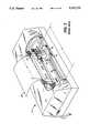
- FIG. 3is a schematic isometric view of a typical carriage type multi-color thermal ink jet printer having the printheads of FIG. 1 integrally attached to disposable ink cartridges.
- FIG. 4is a sample plot of an example energy compensating pulse technique to add heat as required to the printheads.
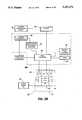
- FIG. 5Ais a schematic diagram of the control circuitry of FIG. 2.
- FIG. 5Bis a schematic diagram of an alternate embodiment of the control circuitry of FIG. 5A.
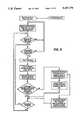
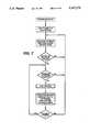
- FIG. 6is a flow chart of the decisions made by the pulse width controller and logic controller of the control circuitry of FIG. 5A.
- FIG. 7is a flow chart of the decisions made by logic complement and logic controller of the control circuitry of FIG. 5B.
- FIG. 8Ais a partially shown, schematic front view of a pagewidth printhead having a plurality of fully functional subunits mounted on opposite sides of a structural bar.
- FIG. 8Bis a partially shown, schematic front view of a pagewidth printhead having a plurality of fully functional subunits mounted on the same side of a structural bar.
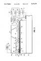
- FIG. 1An enlarged, schematic isometric view of the front face 29 of a typical thermal ink jet printhead 10, showing an array of droplet emitting nozzles 27, is depicted in FIG. 1.
- the lower electrically insulating substrate or heating element plate 28has the multi-layered, thermal transducers 36, including the heating elements 34, and addressing electrodes 33 patterned on surface 30 thereof, while the upper substrate or channel plate 31 has parallel grooves 20 which extend in one direction and penetrate through the upper substrate front face edge 29. The other end of grooves terminate at slanted wall 21.
- the internal recess 24, which is used as the ink supply manifold for the capillary filled ink channels 20,has an open bottom 25 for use an an ink fill hole.
- the surface of the channel plate with the groovesare aligned and bonded to the heater plate 28, so that a respective one of the plurality of heating elements 34 is positioned in each channel, formed by the grooves and the lower substrate or heater plate.
- Inkenters the manifold formed by the recess 24 and the lower substrate 28 through the fill hole 25 and, by capillary action, fills the channels 20 by flowing through an elongated recess 38 formed in the thick film insulative layer 18.
- the ink at each nozzleforms a meniscus, the surface tension of which, together with the slight negative pressure of the ink supply, prevents the ink from weeping therefrom.
- the addressing electrodes 33 on the lower substrate or channel plate 28terminate at terminals 32.
- the upper substrate or channel plate 31is smaller than that of the lower substrate in order that the electrode terminals 32 are exposed and available for wire bonding 15 to the electrodes 14 on the daughter board 19, on which the printhead 10 is permanently mounted.
- Layer 18is a thick film passivation layer, discussed later, sandwiched between upper and lower substrates. This layer is etched to expose the heating elements, thus placing them in a pit 26, and is etched to form the elongated recess 38 to enable ink flow between the manifold 24 and the ink channels 20. In addition, the thick film insulative layer is etched to expose the electrode terminals.
- FIG. 1A cross sectional view of FIG. 1 is taken along view line 2--2 through one channel and shown as FIG. 2 to show how the ink flows from the manifold 24 and around the end 21 of the groove 20 as depicted by arrow 23.
- the ink droplets(not shown) are ejected by control circuitry 48, drivers 49, and power supply 52 in response to receipt of data to be printed.
- the encoder 50monitors when the printhead is in the printing region and the optional microprocessor 60 counts the droplet ejecting electrical pulses applied to each of the heating elements 34. As is disclosed in U.S. Pat. No.
- a plurality of sets of bubble generating heating elements 34 and their addressing electrodes 33are patterned on the polished surface of a (100) silicon wafer.
- the resistive material 34 that serves as the heating elements, and the common return 35the polished surface of the wafer is coated with an underglaze layer 39 such as silicon dioxide, having a thickness of about 2 micrometers.
- the resistive materialmay be a doped polycrystalline silicon which may be deposited by chemical vapor deposition (CVD) or any other well known resistive material such as zirconium boride (ZrB 2 ).
- the common return and the addressing electrodesare typically aluminum leads deposited on the underglaze and over the edges of the heating elements.
- the common return ends or terminals 37 and addressing electrode terminals 32are positioned at predetermined locations to allow clearance for wire bonding to the electrodes 14 of the daughter board 19, after the channel plate 31 is attached to make a printhead.
- the common return 35 and the addressing electrodes 33are deposited to a thickness of 0.5 to 3 micrometers, with the preferred thickness being 1.5 micrometers.
- the lower substrate or heating element plate 28is silicon with an underglaze layer 39 of thermal oxide or other suitable insulative layer such as silicon dioxide.
- Polysilicon heating elements 34are formed and an insulative overglaze layer (not shown) is deposited over the underglaze layer and heating elements thereon.
- This overglaze layermay be either silicon dioxide, thermal oxide, or reflowed polysilicon glass (PSG).
- the thermal oxide layeris typically grown to a thickness of 0.5 to 1.0 micrometer to protect and insulate the heating elements from the conductive ink. Reflowed PSG is usually about 2 micrometers thick.
- the overglaze layeris masked and etched to produce vias therein near the edges of the heating elements for subsequent electrical interface with the aluminum (Al) addressing electrode 33 and Al common return electrode 35.
- Alaluminum
- the overglaze layer in the bubble generating region of the heating element 34is concurrently removed. If other resistive material such as hafnium boride or zirconium boride is used for the heating elements, then other suitable well known insulative materials may be used.
- the next process step in fabricating the thermal transduceris to deposit a pyrolytic silicon nitride layer 17 directly o the exposed polysilicon heating elements, followed by the deposition of about one micrometer thick tantalum layer 12 for cavitational stress protection of the pyrolytic silicon nitride layer 17.
- the pyrolytic silicon nitrideserves two very useful functions. First, it has very good thermal conductivity, so that it produces a thermally efficient resistor structure when deposited directly in contact with the resistor. Secondly, it is one of few materials that is resistant to Ta etches.
- the multi-layered, thermal transducer structureis completed with either 4 wt % CVD PSG or preferably, plasma nitride lead passivation. Either of these materials can be selectively etched off the Al bonding pads and resistor area.
- a two micrometer thick phosphorous doped CVD silicon dioxide film 16is deposited over the entire heating element plate or wafer surface, including the plurality of sets of heating elements and addressing electrodes.
- the passivation film 16provides an ion barrier which will protect the exposed electrodes from the ink.
- Other ion barriersmay be used, such as, for example, polyimide, plasma nitride, as well as the above-mentioned phosphorous doped silicon dioxide, or any combinations thereof.
- An effective ion barrier layeris achieved when its thickness is between 1000 angstroms and 10 micrometers, with the preferred thickness being 1 micrometers.
- the passivation film or layer 16is etched off of the terminal ends of the common return and addressing electrodes for wire bonding later with the daughter board electrodes. This etching of the silicon dioxide film may be by either the wet or dry etching method. Alternatively, the electrode passivation may be accomplished by plasma deposited silicon nitride (Si 3 N 4 ).
- a thick film type insulative layer 18such as, for example, Riston®, Vacrel®, Probimer 52®, or polyimide, is formed on the passivation layer 16 having a thickness of between 10 and 100 micrometers and preferably in the range of 25 to 50 micrometers.
- the insulative layer 18is photolithographically processed to enable etching and removal of those portions of the layer 18 over each heating element (forming recesses 26), the elongated recess 38 for providing ink passage from the manifold 24 to the ink channels 20, and over each electrode terminal 32, 37.
- the elongated recess 38is formed by the removal of this portion of the thick film layer 18.
- the pit 26is formed having walls 42 that exposes each bubble generating area of the multi-layered thermal transducer 36 and walls 41 defining an elongated recess 38 to open the ink channels to the manifold.
- the recess walls 42inhibit lateral movement of each bubble generated by the pulsed heating element which lie at the bottom of recesses 26, and thus promote bubble growth in a direction normal thereto. Therefore, as disclosed in U.S. Pat. No. 4,638,337, the blowout phenomena of releasing a burst of vaporized ink which causes an ingestion of air is avoided.
- the passivated addressing electrodesare exposed to ink along the majority of their length and any pinhole in the normal electrode passivation layer 16 exposes the electrode 33 to electrolysis which would eventually lead to operational failure of the heating element addressed thereby. Accordingly, an added protection of the addressing electrode is obtained by the thick film layer 18, since the electrodes are passivated by two overlapping layers, passivation layer 16 and a thick film layer 18.
- the channel plateis formed from a (100) silicon wafer to produce a plurality of upper substrates 31 for the printhead.
- the heating element plate 28is also obtained from a wafer or wafer sized structure (not shown) containing a plurality thereof. Relatively large rectangular through recesses and a plurality of sets of equally, spaced parallel V-groove recesses are etched in one surface of the wafer (not shown). These recesses will eventually become the ink manifolds 24 and ink channels 20 of the printheads.
- the channel plate and heating element plate containing wafersare aligned and bonded together, then diced into a plurality of individual printheads.
- One of the dicing cutsproduces end face 29, opens one end of the elongated V-groove recesses 20 producing nozzles 27.
- the other ends of the V-groove recesses 20remain closed by end 21.
- the alignment and bonding of the above-mentioned wafersplaces the ends 21 of each set of channels 20 directly over elongated recess 38 in the thick film insulative layer 18 as shown in FIG. 2, enabling the flow of ink into the channels from the manifold 24 as depicted by arrow 23.
- a typical multicolor thermal ink jet printer 11is shown containing several disposable ink supply cartridges 22, each with an integrally attached printhead 10 of the present invention.
- the cartridge and printhead combinationare removably mounted on a translatable carriage 40. Curing the printing mode, the carriage reciprocates back and forth on, for example, guide rails 43 parallel to the recording medium 44 as depicted by arrow 45.
- the end-to-end travel distance of the carriage and printheadsis shown as distance B.
- the recording mediumsuch as, for example, paper
- the recording mediumis held stationary while the carriage is moving in one direction and, prior to the carriage moving in a reverse direction, the paper is stepped in the direction of arrow 46 a distance equal to the height of the swath of data printed thereon by the printheads 10 during traversal in one direction across the paper.
- the width of the recording mediumis the printing zone or region during the carriage traversal and is indicated as distance A.
- the overall travel distance Bis larger than the printing region A.
- an encoder 50(see FIGS. 2 and 5) must be used to monitor when the printheads are within the printing region.
- the dropletsare ejected on demand from the nozzles 27 in front face 29 of the printheads along the trajectories 47 to the paper.
- the front face of the printheadis spaced from the paper a distance of between 0.01 and 0.1 inch, with the preferred distance being about 0.02 inches.
- the stepping tolerance for the paper and the linear deviation of the printheadsare held within acceptable limits to permit contiguous swaths of information to be printed without gaps or overlaps.
- Each cartridge 40contains a different colored ink, one black and one to three additional cartridges of different selected colors.
- the combined cartridge and printheadis removed and discarded after the ink supply in the cartridge has been depleted.
- some of the nozzlesdo not eject droplets during one complete carriage traversal and, generally, none of the nozzles eject droplets as the printheads move beyond the edge of the paper. While at this end of a carriage traversal, there is a small dwell time while the paper is being stepped one swath in height in the direction of arrow 46.
- the printhead of the prior art printerscool down.
- the printheads of the present inventionare kept at a constant operating temperature by the application of electrical or energy pulses to the heating element not ejecting droplets having insufficient magnitude to vaporize the ink.
- This supplemental heatkeeps the operating temperature of the printhead constant.
- the number of unused heating elements, the pulse widths, and/or the power of the supplemental pulsescontrol the printhead temperature while it is in the printing mode.
- a zero data detector 54enables all heating elements of the printhead to be pulsed with non-droplet ejecting or subthreshold pulses to maintain the operating temperature of the printhead substantially constant.
- the ambient printer temperatureis checked by a temperature sensor 55 located within the printer (not shown) and in the vicinity of the printhead 10 for a reference temperature which the logic controller uses to control the compensating energy applied by subthreshold pulses.
- the temperature of the printheadcould be used instead of the ambient printer temperature.
- This reference temperatureis checked at startup, when entering the printing mode, and at the conclusion of printing a predetermined number of full pages, rather than sensing the printhead temperature continually or frequently such as during or after each swath of printed information as required by the prior art.
- this inventiondoes not need to continually check the printhead temperature or even check for a reference temperature more frequently than after printing more than one page.
- a pulse count look up table 51in response to the pulse counter 61, which counts the droplet ejecting pulses required by the data to be printed, determines the umber and width of the nondroplet ejecting (subthreshold) pulses in conjunction with the subthreshold pulse width controller 56 and enables the logic controller to apply the required subthreshold pulses having the appropriate pulse width to the heating elements not ejecting droplets.
- a microprocessor 60counts the droplet ejecting pulses per heating element per unit of time, so that if the number of heating elements used and/or the rate of droplets expelled are not within predetermined values, supplemental heat is applied to the printhead by subthreshold pulsing of the least used heating elements.
- Subthreshold pulsesare not capable of vaporizing the ink, so that droplets are not ejected.
- a consequence of using supplemental heat to keep the temperature of the printhead constant during printingis that the average device temperature will be higher than it would be otherwise. However, this is an advantage, if the temperature is kept below a predetermined maximum temperature, whereat the printhead begins to fail. This maximum temperature is about 70° C.
- the inks usedcomprise ethylene glycol and a water base, but varies with different ink formulations and ink channel geometries. Below 70° C., the drop velocity becomes more uniform as the temperature is increased. At 20° C., some ink channels of the printhead having water based ink formulations have been observed to have marginally acceptable droplet velocities. The droplet velocity increases to a highly satisfactory range with a moderate increase in printhead temperature. The ideal operating point depends on ink and device parameters, but in the present case would appear to be roughly 30° C. to 50° C. An additional advantage of operating at elevated temperature is that the ink viscosity decreases, so that refill times of the channels may be decreased, enabling higher printing frequencies.
- the printhead 10has a heat sink 71 with a predetermined heat dissipating capacity, so that the heat added to the printhead by the droplet ejecting pulses and the subthreshold pulses will be dissipated at a known rate and taken into account by the pulse count look up table 51 and/or the optional microprocessor 60.
- FIG. 4one embodiment of this invention is shown in which, for example, a 48 jet or channel printhead is used, printing up to two channels at a time.
- the 48 channelsare being pulsed 2 at a time and channels 1, 2, 3, 24, 25, 26 and 48 are assumed to have printed.
- the shorter pulses during the compensation cycleare provided so that the total energy dissipated in the time interval associated with a group of 48 pixels is constant. Since the carriage is moving continuously, it is necessary to finish printing all 48 jets in a fraction of the time it takes to get from one pixel to the next, or the dot or pixel pattern will be too jagged.
- the printing cycleis composed of 24 intervals of 5 ⁇ sec (120 ⁇ sec total), during which up to two channels will be fired or energized at a time using about 3 ⁇ sec duration pulses.
- E cthe compensating energy
- a variety of method or embodimentsmay be devised for implementing the logic for the energy compensation pulses.
- One methodwould be to count the pulses during the printing cycle and decrement a counter for the compensation cycle accordingly. Referring to FIG. 5A, this method does not keep track of which heating elements were fired, unless the optional microprocessor 60 is used, and would simply cycle through the heating elements not being used to eject droplets until enough compensating pulses were fired.
- the pulse counter 61, zero data detector 54 and logic controller 58 of the control circuitry 48receive data to be printed in the form of digitized data signals.
- the encoder 50provides signals indicative of the location of the printhead 10, relative to the printing region A of FIG. 3, to the logic controller 58 and subthreshold pulse width controller 56.
- the pulse counter 61determines how many jet or heating elements are being fired during a particular time interval. Jets fired have a pulse width given by the ejection pulse controller 62. In the event that the zero data detector 54 indicates that no jets are to be fired (i.e., no droplets are to be ejected as when a new page of printing has not begun, or the printhead has reached the end of a line, or during white space within a line), it indicates to the logic controller 58 that subthreshold pulse firing may occur.
- the pulse count look up table 51compares the number of droplet ejection pulses which have recently been first or are about to be fired, and indicates to the subthreshold pulse width controller 56 how many and how wide the subthreshold pulses should be to bring the printhead 10 to the desired operating point.
- the power supply 52provides a constant voltage V o to the common return electrode 35.
- the heating elements 34are pulsed with this voltage through drivers 49 which are connected to the printhead addressing electrodes 33 and to ground.
- the electrical pulses applied to the heating elements or resistors 34have a constant amplitude and the width is varied to eject a droplet or provide only supplemental heat with pulse widths insufficient to vaporize ink.
- Clock 53provides the timing for the logic controller 58.
- the control circuitry 48may optionally contain a look up table 57 (shown in dashed line) which receives input signals representative of the ambient temperature from temperature sensor 55 located within the printer (not shown) in the vicinity of the printhead or optionally thereon. Based upon the temperature sensor, the subthreshold pulse width controller signals the logic controller for supplemental heat generating electrical pulses insufficient to eject droplets.
- An optional microprocessor 60keeps track of which heating elements have not been fired very often and employs those heating elements which have not been used often to do the threshold pulsing, in order to average out the overall number of pulses for each heating element for lifetime purposes. This is accomplished by counting the number of droplet-ejecting pulses each heating element received during a predetermined time period, such as, for example, during the printing of a swath of information. This count per heating element could be stored and averaged or simply erased after each printed swath or printed page.
- a device 63 for determining the logical complement of the printing datais given to the subthreshold pulse width controller 67 so that those heating elements which are not fired to eject droplets are automatically pulsed with subthreshold pulses. This ensures that each heating element experiences the same number of pulses for lifetime purposes, although some experience a greater number of droplet ejection pulses.
- the pulse width controller 56 in the control circuitry 48 of FIG. 5Ais shown in the flow chart of FIG. 6.
- the ink channelsare primed and the heating elements are all pulsed with electrical current pulses having sufficient magnitude or average power to vaporize the ink in contact therewith and eject nozzle clearing droplets in an ink collection recess or absorbent material forming part of a maintenance station (not shown).
- the printhead warmupis continued with application of subthreshold electrical pulses to the heating elements.
- subthresholdit is meant those pulses having insufficient energy or average power to vaporize ink and expel ink droplets.
- the location of the printheadis checked to see if it is within the printing region A as shown in FIG. 3. If not, the printhead is pulsed with subthreshold pulses to provide supplemental heating while it is moved into proper position for printing. Once the printhead is in the printing region, droplets are ejected and propelled to a recording medium 44.
- the pulse counter 61counts the number of pulses which eject droplets and the logic controller 58 determines the pulses per clock time unit, that is the printing rate or density, and compares this rate or density with a minimum value required to maintain the operating temperature of the printhead within the appropriate temperature range.
- the microprocessor 60identifies which nozzles were fired; i.e. used to expel droplets. If the printing density is sufficient to maintain the printhead operating temperature sufficiently constant, printing is continued without supplemental heating. If not, the number and width of subthreshold pulses required are determined by the logic controller and those heating elements not being used to eject droplets are pulsed with the subthreshold pulse. If desired, the subthreshold pulses can be applied only to those heating elements which have not ejected a droplet during the time period for which the droplet rate or density was measured. For example, at intermediate points along a swath of printed droplets or at the end of a printed swath or both.
- the operating temperature of the printhead of the present inventionis maintained substantially constant within the appropriate temperature without the need for continually measuring the printhead temperature and modifying the printing speed to cool it down or add heat to boost the temperature until the printhead sensor reads the desired value.
- a temperature sensor 55 within the printeris used periodically during standby or initial start-up of printing, but constant reference to it is not required.
- the decisions made by the control circuitry 48A of FIG. 5Bare shown in the flow chart of FIG. 7.
- the ink channelsare primed and the heating elements pulsed to eject nozzle clearing droplets when the printing mode is activated. After a predetermined number of droplets are ejected from each nozzle, the printhead warmup is continued with the application of subthreshold pulses to the heating elements.
- the location of the printheadis checked to see if it is within the printing region by the encoder 50. If not, the printhead is pulsed with subthreshold pulses to provide supplemental heating while it is being moved into the proper position for printing. Once the printhead is in the printing region, droplets are ejected and propelled to the recording medium 44.
- the logical complement 63identifies those heating elements not being used to eject droplets, and in response to the logical complement input, the subthreshold pulse width controller 67 and ejection pulse controller 62 via logic controller 58 apply respective pulses to each heating element.
- all of the heating elementsare fired or pulsed with either droplet ejecting pulses or subthreshold pulses during the actual printing operation.
- only subthreshold pulsesare applied to the heating elements.
- the subthreshold pulse widthis determined by the ambient temperature sensor 55 and the known heat transfer rate from the heat sink 71.
- E p +E cE max .
- E cshould probably be somewhat less than E max -E p because no heat is being carried off by ejected drops during the compensation cycle.
- the advantage of using less energy compensationis that it would be easier to maintain a thermal equilibrium which did not approach the upper operating temperature for a longer period of time.
- Energy compensationwill be required whenever printing is occurring or about to occur. In particular, energy compensation should continue at its maximum rate during carriage pauses at the end of travel. It should also occur just preceding starting to print. Warmup time should not be objectionably long, but in a one page per minute printer 1-4 seconds should be satisfactory for a large part of the temperature rise occurs within 3 seconds.
- the heat sinkingshould be designed so that the device temperature is raised for the most part within a few seconds, and then rises much slower after that. Energy compensation could also be applied for the longer term heating effects, e.g., by decrementing a counter a certain number of pulses for each line printed.
- the other heat sink requirementis that the device temperature remain in the optimal range (e.g., 40° C. ⁇ 10° C.).
- Energy compensationmay also be controlled by modifying the pulse width, t c , depending on the number of channels fired during the printing cycle.
- short compensating pulsesare fired only during the compensation cycle.
- short pulsesare fired during the printing cycle as well, with the pulse width widened for those channels where printing is desired.
- the minimum pulse width incrementwould be determined by the fastest clock in the system, which might typically be 10-20 MHz.
- Another way to control the energy compensationis to modify its pulse power, but this is more difficult to implement. It has been assumed here that the compensation energy is provided by the same heating elements responsible for printing, but this is not a requirement.
- One or more special heating elements (not shown) for supplying only supplemental heatmay be formed anywhere on the heating element plate 28, preferably in a location where they do not contact the ink.
- Peak power required for bubble formationis reduced, since spot size increases with device temperature as well as print pulse condition.
- Operation at elevated temperatureis expected to decrease ink viscosity within the device, and improve channel refill times.
- An additional feature that might prove usefulis a temperature sensor on the printhead that measures the absolute temperature.
- the energy compensation schemecould then be modified, for example, through the use of lookup tables to provide the desired device temperature independent of ambient temperature or length of time the printer has been operating.
- subthreshold pulseswould keep all of the subunits or modules making up the page width printhead at the same temperature, so that they would produce droplets having the same volume and the printed spot size would be uniform.
- subthreshold temperature compensating pulsesin relation to the density of printing by each module, they all could be maintained within the desired operating temperature without the need of individual temperature sensors on each printhead subunits, but only one within the pagewidth printhead structural bar.
- a printheadis composed of a plurality of fully functional, small individual printhead subunits. Each subunit could be used individually as a carriage type printhead capable of being scanned across a recording medium to print a swath of pixels or dots of ink.
- a plurality of the printhead subunits 66are mounted on a structural bar 68 which could either be translated across a recording medium, (not shown) to print partial pages (e.g., one large swath of information) or be fixed for page width printing where the recording medium is moved thereby at a constant velocity.
- the subunitsare alternately mounted on opposite sides of the bar with spaces between subunits on the same side of the bar.
- a single temperature sensor 69 mounted on the baris used to establish a reference temperature for determining the number and/or width of the subthreshold pulses applied to the heating elements of each printhead subunit 66.
- the control circuitry 48C or 48Deither uses the logic complement (not shown) of the data to be printed to apply subthreshold pulses (those pulses having a magnitude insufficient to vaporize ink) to all heating elements in each subunit not ejecting droplets or counts the droplet ejecting pulses and through a lookup table determines the number and pulse width of the subthreshold pulses of predetermined heating elements not ejecting droplets.
- a microprocessor 60Bcould be optionally used to count the number of droplets ejected by each heating element in each subunit and apply subthreshold pulses to the heating elements least used to eject droplets.
- the droplet ejecting or subthreshold pulsesare applied by the control circuitry via the drivers 49.
- the temperature sensorprovides a reference temperature of the structural bar 68 or ambient temperature which is only used at startup and then periodically, but infrequently, as a reference parameter.
- the primary control of the operating temperatureis by monitoring the heat energy applied to the printhead subunits in the form of droplet ejecting or subthreshold pulses per unit of time after the reference or ambient temperature has been established. Thus the desired operating temperature of each subunit is maintained within the same desired operating temperature without the need of individual temperature sensors on each printhead subunit.
Landscapes
- Engineering & Computer Science (AREA)
- Manufacturing & Machinery (AREA)
- Particle Formation And Scattering Control In Inkjet Printers (AREA)
- Ink Jet (AREA)
Abstract
Description
TABLE 1 ______________________________________ Energy Compensating Pulse Widths (μsec) t.sub.p /t.sub.c t on 2 kHz t off 3 kHz t off ______________________________________ 4 .75 2.9 1.2 3 1.0 3.9 1.5 2 1.5 5.8 2.3 ______________________________________
Claims (23)
Priority Applications (1)
| Application Number | Priority Date | Filing Date | Title |
|---|---|---|---|
| US07/572,075US5107276A (en) | 1989-07-03 | 1990-08-24 | Thermal ink jet printhead with constant operating temperature |
Applications Claiming Priority (2)
| Application Number | Priority Date | Filing Date | Title |
|---|---|---|---|
| US37516289A | 1989-07-03 | 1989-07-03 | |
| US07/572,075US5107276A (en) | 1989-07-03 | 1990-08-24 | Thermal ink jet printhead with constant operating temperature |
Related Parent Applications (1)
| Application Number | Title | Priority Date | Filing Date |
|---|---|---|---|
| US37516289AContinuation-In-Part | 1989-07-03 | 1989-07-03 |
Publications (1)
| Publication Number | Publication Date |
|---|---|
| US5107276Atrue US5107276A (en) | 1992-04-21 |
Family
ID=27006926
Family Applications (1)
| Application Number | Title | Priority Date | Filing Date |
|---|---|---|---|
| US07/572,075Expired - LifetimeUS5107276A (en) | 1989-07-03 | 1990-08-24 | Thermal ink jet printhead with constant operating temperature |
Country Status (1)
| Country | Link |
|---|---|
| US (1) | US5107276A (en) |
Cited By (103)
| Publication number | Priority date | Publication date | Assignee | Title |
|---|---|---|---|---|
| US5281980A (en)* | 1989-03-31 | 1994-01-25 | Canon Kabushiki Kaisha | Ink jet recording head |
| US5361090A (en)* | 1990-10-04 | 1994-11-01 | Canon Kabushiki Kaisha | Image recording apparatus and method for maintaining image quality after recording interruption |
| EP0627313A3 (en)* | 1993-05-26 | 1995-05-03 | Canon Kk | Ink jet recording head and ink jet recording apparatus using same. |
| US5422664A (en)* | 1993-06-25 | 1995-06-06 | Xerox Corporation | Method and apparatus for maintaining constant drop size mass in thermal ink jet printers |
| US5459498A (en)* | 1991-05-01 | 1995-10-17 | Hewlett-Packard Company | Ink-cooled thermal ink jet printhead |
| US5475405A (en)* | 1993-12-14 | 1995-12-12 | Hewlett-Packard Company | Control circuit for regulating temperature in an ink-jet print head |
| EP0700790A3 (en)* | 1994-09-09 | 1996-06-19 | Canon Kk | Printing apparatus and method for controlling the temperature of the printing head of such printing apparatus |
| US5576745A (en)* | 1993-05-27 | 1996-11-19 | Canon Kabushiki Kaisha | Recording apparatus having thermal head and recording method |
| US5585825A (en)* | 1994-11-25 | 1996-12-17 | Xerox Corporation | Ink jet printer having temperature sensor for replaceable printheads |
| US5629724A (en)* | 1992-05-29 | 1997-05-13 | Xerox Corporation | Stabilization of the free surface of a liquid |
| US5673069A (en)* | 1991-05-01 | 1997-09-30 | Hewlett-Packard Company | Method and apparatus for reducing the size of drops ejected from a thermal ink jet printhead |
| EP0622202A3 (en)* | 1993-04-30 | 1997-10-22 | Hewlett Packard Co | Themal ink jet printer with start-up algorithm. |
| US5686943A (en)* | 1994-11-25 | 1997-11-11 | Xerox Corporation | Ink jet printer having temperature sensor for periodic contact with printhead |
| US5736995A (en)* | 1991-05-01 | 1998-04-07 | Hewlett-Packard Company | Temperature control of thermal inkjet printheads by using synchronous non-nucleating pulses |
| US5751302A (en)* | 1996-03-29 | 1998-05-12 | Xerox Corporation | Transducer power dissipation control in a thermal ink jet printhead |
| US5760797A (en)* | 1989-09-18 | 1998-06-02 | Canon Kabushiki Kaisha | Ink jet recording head with adjustable temperature sensor and ink jet recording system having the same |
| US5790144A (en)* | 1996-09-25 | 1998-08-04 | Lexmark International, Inc. | Method of controlling an operating temperature of a printhead in an ink jet cartridge assembly |
| US5798772A (en)* | 1990-06-15 | 1998-08-25 | Canon Kabushiki Kaisha | Driving method ink jet head |
| US5808639A (en)* | 1995-04-12 | 1998-09-15 | Eastman Kodak Company | Nozzle clearing procedure for liquid ink printing |
| US5808632A (en)* | 1990-02-02 | 1998-09-15 | Canon Kabushiki Kaisha | Recording apparatus and method using ink jet recording head |
| US5847674A (en)* | 1996-05-02 | 1998-12-08 | Moore Business Forms, Inc. | Apparatus and methods for maintaining optimum print quality in an ink jet printer after periods of inactivity |
| US5963233A (en)* | 1992-07-22 | 1999-10-05 | Canon Kabushiki Kaisha | Jet recording method |
| US5969730A (en)* | 1994-11-07 | 1999-10-19 | Canon Aptex Inc. | Printer |
| US6027203A (en)* | 1997-12-11 | 2000-02-22 | Lexmark International, Inc. | Page wide ink-jet printer and method of making |
| US6076919A (en)* | 1991-08-12 | 2000-06-20 | Canon Kabushiki Kaisha | Jet recording method |
| US6102515A (en)* | 1997-03-27 | 2000-08-15 | Lexmark International, Inc. | Printhead driver for jetting heaters and substrate heater in an ink jet printer and method of controlling such heaters |
| US6170936B1 (en) | 1999-07-23 | 2001-01-09 | Lexmark International, Inc. | Substrate heater circuit topology for inkjet printhead |
| US6193349B1 (en) | 1997-06-18 | 2001-02-27 | Lexmark International, Inc. | Ink jet print cartridge having active cooling cell |
| US6211970B1 (en) | 1998-11-24 | 2001-04-03 | Lexmark International, Inc. | Binary printer with halftone printing temperature correction |
| US6213579B1 (en) | 1998-11-24 | 2001-04-10 | Lexmark International, Inc. | Method of compensation for the effects of thermally-induced droplet size variations in ink drop printers |
| US6227641B1 (en)* | 1996-07-02 | 2001-05-08 | Canon Kabushiki Kaisha | Ink jet printing system having heat keeping function |
| US6231153B1 (en) | 1997-04-25 | 2001-05-15 | Hewlett-Packard Company | Method and apparatus for controlling an ink-jet print head temperature |
| US6231152B1 (en)* | 1989-09-05 | 2001-05-15 | Canon Kabushiki Kaisha | Ink jet recording method employing control of ink temperature |
| US6276777B1 (en) | 1998-07-21 | 2001-08-21 | Hewlett-Packard Company | Variable maximum operating temperature for a printhead |
| US6296350B1 (en)* | 1997-03-25 | 2001-10-02 | Lexmark International, Inc. | Ink jet printer having driver circuit for generating warming and firing pulses for heating elements |
| EP1093929A3 (en)* | 1999-10-20 | 2001-10-04 | Nec Corporation | Ink jet printer and its preliminary driving method |
| US6299273B1 (en) | 2000-07-14 | 2001-10-09 | Lexmark International, Inc. | Method and apparatus for thermal control of an ink jet printhead |
| US6299272B1 (en)* | 1999-10-28 | 2001-10-09 | Xerox Corporation | Pulse width modulation for correcting non-uniformity of acoustic inkjet printhead |
| US6315379B1 (en)* | 1999-10-26 | 2001-11-13 | Xerox Corporation | Systems and methods for selectively blocking image data |
| US6322189B1 (en) | 1999-01-13 | 2001-11-27 | Hewlett-Packard Company | Multiple printhead apparatus with temperature control and method |
| US6382773B1 (en) | 2000-01-29 | 2002-05-07 | Industrial Technology Research Institute | Method and structure for measuring temperature of heater elements of ink-jet printhead |
| US6390585B1 (en) | 1998-07-21 | 2002-05-21 | Hewlett-Packard Company | Selectively warming a printhead for optimized performance |
| US6394571B1 (en)* | 1994-07-25 | 2002-05-28 | Canon Kabushiki Kaisha | Method and apparatus for controlling printing operation with externally supplied parameters |
| US6422677B1 (en) | 1999-12-28 | 2002-07-23 | Xerox Corporation | Thermal ink jet printhead extended droplet volume control |
| US6443555B1 (en)* | 1999-03-16 | 2002-09-03 | Silverbrook Research Pty Ltd | Pagewidth wide format printer |
| US20020137363A1 (en)* | 1998-08-24 | 2002-09-26 | Thakur Randhir P.S. | Methods to form electronic devices |
| US20020140755A1 (en)* | 2000-07-26 | 2002-10-03 | Ulrich Hetzer | Arrangement and method for data follow-up for warmup cycles of ink jet print heads |
| US6565176B2 (en) | 2001-05-25 | 2003-05-20 | Lexmark International, Inc. | Long-life stable-jetting thermal ink jet printer |
| US6598952B2 (en)* | 1988-07-26 | 2003-07-29 | Canon Kabushiki Kaisha | Liquid jet recording head having controller for controlling temperature distribution |
| US6601941B1 (en) | 2000-07-14 | 2003-08-05 | Christopher Dane Jones | Method and apparatus for predicting and limiting maximum printhead chip temperature in an ink jet printer |
| US6644774B1 (en) | 2002-08-22 | 2003-11-11 | Xerox Corporation | Ink jet printhead having out-of-ink detection using temperature monitoring system |
| US6652058B2 (en)* | 2001-02-22 | 2003-11-25 | Canon Kabushiki Kaisha | Recording apparatus and recording control method, and ink jet recording method and apparatus |
| US6655775B1 (en) | 1996-10-15 | 2003-12-02 | Hewlett-Packard Development Company, L.P. | Method and apparatus for drop weight encoding |
| US6672711B2 (en) | 2000-08-04 | 2004-01-06 | Benq Corporation | Driving circuit capable of maintaining heat equilibrium of a print head nozzle |
| US6672706B2 (en)* | 1997-07-15 | 2004-01-06 | Silverbrook Research Pty Ltd | Wide format pagewidth inkjet printer |
| US6679584B2 (en) | 1997-07-15 | 2004-01-20 | Silverbrook Research Pty Ltd. | High volume pagewidth printing |
| US20040135848A1 (en)* | 1997-07-15 | 2004-07-15 | Kia Silverbrook | Printing mechanism for a wide format pagewidth inkjet printer |
| US20040145763A1 (en)* | 2003-01-23 | 2004-07-29 | Patrick Dougherty | Burst mode for printing devices |
| US6808243B1 (en) | 2003-05-20 | 2004-10-26 | Xerox Corporation | Thermal inkjet print head with blended enable trains |
| US20050007418A1 (en)* | 1997-07-15 | 2005-01-13 | Kia Silverbrook | Printhead assembly arrangement for a wide format pagewidth inkjet printer |
| US6857724B2 (en) | 1997-07-15 | 2005-02-22 | Silverbrook Research Pty Ltd | Print assembly for a wide format pagewidth printer |
| US20050073555A1 (en)* | 2003-10-03 | 2005-04-07 | Chien-Chih Huang | Printing apparatus and method for maintaining temperature of a printhead |
| US20050083392A1 (en)* | 1997-07-15 | 2005-04-21 | Kia Silverbrook | Wide format pagewidth inkjet printer |
| AU2004201741B2 (en)* | 1999-03-16 | 2005-06-23 | Silverbrook Research Pty Ltd | Wide format printer |
| US20050157080A1 (en)* | 1997-07-15 | 2005-07-21 | Kia Silverbrook | Printing mechanism having wide format printing zone |
| US20060152769A1 (en)* | 2005-01-10 | 2006-07-13 | Xerox Corporation | Method and apparatus using pixel spot size control for reducing intercolor bleed |
| US20070002097A1 (en)* | 1997-07-15 | 2007-01-04 | Kia Silverbrook | Print assembly for a wide format pagewidth printer |
| US20070040867A1 (en)* | 1997-07-15 | 2007-02-22 | Silverbrook Research Pty Ltd | Nozzle assembly with heat deflected actuator |
| US20080062221A1 (en)* | 1997-07-15 | 2008-03-13 | Silverbrook Research Pty Ltd | Modular self-capping wide format print assembly |
| US20100182362A1 (en)* | 2009-01-20 | 2010-07-22 | Brother Kogyo Kabushiki Kaisha | Recording apparatus |
| US20100188445A1 (en)* | 1998-11-09 | 2010-07-29 | Silverbrook Research Pty Ltd | Card-type printing device |
| US20100225724A1 (en)* | 1998-11-09 | 2010-09-09 | Silverbrook Research Pty Ltd | Printing unit incorporating integrated data connector, media supply cartridge and print head assembly |
| US20100309252A1 (en)* | 1997-07-15 | 2010-12-09 | Silverbrook Research Pty Ltd | Ejection nozzle arrangement |
| US20110096125A1 (en)* | 1997-07-15 | 2011-04-28 | Silverbrook Research Pty Ltd | Inkjet printhead with nozzle layer defining etchant holes |
| US20110109700A1 (en)* | 1997-07-15 | 2011-05-12 | Silverbrook Research Pty Ltd | Ink ejection mechanism with thermal actuator coil |
| US7950777B2 (en) | 1997-07-15 | 2011-05-31 | Silverbrook Research Pty Ltd | Ejection nozzle assembly |
| US20110134193A1 (en)* | 1997-07-15 | 2011-06-09 | Silverbrook Research Pty Ltd | Nozzle arrangement with an actuator having iris vanes |
| US20110157280A1 (en)* | 1997-07-15 | 2011-06-30 | Silverbrook Research Pty Ltd | Printhead nozzle arrangements with magnetic paddle actuators |
| US20110175970A1 (en)* | 1997-07-15 | 2011-07-21 | Silverbrook Research Pty Ltd | Inkjet printhead integrated circuit incorporating fulcrum assisted ink ejection actuator |
| US20110211020A1 (en)* | 1997-07-15 | 2011-09-01 | Silverbrook Research Pty Ltd | Printhead micro-electromechanical nozzle arrangement with motion-transmitting structure |
| US20110211025A1 (en)* | 1997-07-15 | 2011-09-01 | Silverbrook Research Pty Ltd | Printhead nozzle having heater of higher resistance than contacts |
| US20110228008A1 (en)* | 1997-07-15 | 2011-09-22 | Silverbrook Research Pty Ltd | Printhead having relatively sized fluid ducts and nozzles |
| US8029102B2 (en) | 1997-07-15 | 2011-10-04 | Silverbrook Research Pty Ltd | Printhead having relatively dimensioned ejection ports and arms |
| US8061812B2 (en) | 1997-07-15 | 2011-11-22 | Silverbrook Research Pty Ltd | Ejection nozzle arrangement having dynamic and static structures |
| CN101554801B (en)* | 2008-04-10 | 2012-07-18 | 佳能株式会社 | Inkjet printing apparatus and inkjet printing method |
| US8292392B2 (en) | 2010-07-15 | 2012-10-23 | Xerox Corporation | System and method for modifying operation of an inkjet printer to accommodate changing environmental conditions |
| US8789939B2 (en) | 1998-11-09 | 2014-07-29 | Google Inc. | Print media cartridge with ink supply manifold |
| US8823823B2 (en) | 1997-07-15 | 2014-09-02 | Google Inc. | Portable imaging device with multi-core processor and orientation sensor |
| US8866923B2 (en) | 1999-05-25 | 2014-10-21 | Google Inc. | Modular camera and printer |
| US8896724B2 (en) | 1997-07-15 | 2014-11-25 | Google Inc. | Camera system to facilitate a cascade of imaging effects |
| US8902333B2 (en) | 1997-07-15 | 2014-12-02 | Google Inc. | Image processing method using sensed eye position |
| US8902340B2 (en) | 1997-07-12 | 2014-12-02 | Google Inc. | Multi-core image processor for portable device |
| US8908075B2 (en) | 1997-07-15 | 2014-12-09 | Google Inc. | Image capture and processing integrated circuit for a camera |
| US8936196B2 (en) | 1997-07-15 | 2015-01-20 | Google Inc. | Camera unit incorporating program script scanner |
| US9055221B2 (en) | 1997-07-15 | 2015-06-09 | Google Inc. | Portable hand-held device for deblurring sensed images |
| US9259922B2 (en) | 2013-01-30 | 2016-02-16 | Hewlett-Packard Development Company, L.P. | Thermal ink jet printing |
| US9975330B1 (en) | 2017-04-17 | 2018-05-22 | Xerox Corporation | System and method for generation of non-firing electrical signals for operation of ejectors in inkjet printheads |
| US9981465B1 (en) | 2017-02-20 | 2018-05-29 | RF Printing Technologies LLC | Inkjet printing apparatus with firing or heating waveform selector |
| US10457048B2 (en) | 2014-10-30 | 2019-10-29 | Hewlett-Packard Development Company, L.P. | Ink jet printhead |
| US10532568B2 (en) | 2016-04-14 | 2020-01-14 | Hewlett-Packard Development Company, L.P. | Fire pulse width adjustment |
| US20200070500A1 (en)* | 2017-05-01 | 2020-03-05 | Hewlett-Packard Development Company, L.P. | Pause start-up routine of imaging device |
| US11173711B2 (en) | 2017-11-22 | 2021-11-16 | Hewlett-Packard Development Company, L.P. | Fluidic die regulation modules |
| US11260656B2 (en) | 2017-12-15 | 2022-03-01 | Hewlett-Packard Development Company, L.P. | Setpoint registers to adjust firing pulses |
Citations (14)
| Publication number | Priority date | Publication date | Assignee | Title |
|---|---|---|---|---|
| US4326206A (en)* | 1980-06-30 | 1982-04-20 | Xerox Corporation | Method of reducing cross talk in ink jet arrays |
| US4350989A (en)* | 1979-03-19 | 1982-09-21 | Hitachi, Ltd. | Ink-jet printing apparatus |
| US4490728A (en)* | 1981-08-14 | 1984-12-25 | Hewlett-Packard Company | Thermal ink jet printer |
| US4499479A (en)* | 1982-08-30 | 1985-02-12 | International Business Machines Corporation | Gray scale printing with ink jet drop-on demand printing head |
| US4532530A (en)* | 1984-03-09 | 1985-07-30 | Xerox Corporation | Bubble jet printing device |
| US4536774A (en)* | 1983-04-01 | 1985-08-20 | Fuji Xerox Co., Ltd. | Thermal head drive circuit |
| US4566813A (en)* | 1983-09-27 | 1986-01-28 | Mitsubishi Denki Kabushiki Kaisha | Dot-matrix print controller |
| US4571599A (en)* | 1984-12-03 | 1986-02-18 | Xerox Corporation | Ink cartridge for an ink jet printer |
| US4712172A (en)* | 1984-04-17 | 1987-12-08 | Canon Kabushiki Kaisha | Method for preventing non-discharge in a liquid jet recorder and a liquid jet recorder |
| US4712930A (en)* | 1985-04-19 | 1987-12-15 | Matsushita Electric Industrial Co., Ltd. | Gradation thermal printhead and gradation heat transfer printing apparatus |
| USRE32572E (en)* | 1985-04-03 | 1988-01-05 | Xerox Corporation | Thermal ink jet printhead and process therefor |
| US4719472A (en)* | 1982-06-18 | 1988-01-12 | Canon Kabushiki Kaisha | Ink jet recording head |
| US4791435A (en)* | 1987-07-23 | 1988-12-13 | Hewlett-Packard Company | Thermal inkjet printhead temperature control |
| US4910528A (en)* | 1989-01-10 | 1990-03-20 | Hewlett-Packard Company | Ink jet printer thermal control system |
- 1990
- 1990-08-24USUS07/572,075patent/US5107276A/ennot_activeExpired - Lifetime
Patent Citations (14)
| Publication number | Priority date | Publication date | Assignee | Title |
|---|---|---|---|---|
| US4350989A (en)* | 1979-03-19 | 1982-09-21 | Hitachi, Ltd. | Ink-jet printing apparatus |
| US4326206A (en)* | 1980-06-30 | 1982-04-20 | Xerox Corporation | Method of reducing cross talk in ink jet arrays |
| US4490728A (en)* | 1981-08-14 | 1984-12-25 | Hewlett-Packard Company | Thermal ink jet printer |
| US4719472A (en)* | 1982-06-18 | 1988-01-12 | Canon Kabushiki Kaisha | Ink jet recording head |
| US4499479A (en)* | 1982-08-30 | 1985-02-12 | International Business Machines Corporation | Gray scale printing with ink jet drop-on demand printing head |
| US4536774A (en)* | 1983-04-01 | 1985-08-20 | Fuji Xerox Co., Ltd. | Thermal head drive circuit |
| US4566813A (en)* | 1983-09-27 | 1986-01-28 | Mitsubishi Denki Kabushiki Kaisha | Dot-matrix print controller |
| US4532530A (en)* | 1984-03-09 | 1985-07-30 | Xerox Corporation | Bubble jet printing device |
| US4712172A (en)* | 1984-04-17 | 1987-12-08 | Canon Kabushiki Kaisha | Method for preventing non-discharge in a liquid jet recorder and a liquid jet recorder |
| US4571599A (en)* | 1984-12-03 | 1986-02-18 | Xerox Corporation | Ink cartridge for an ink jet printer |
| USRE32572E (en)* | 1985-04-03 | 1988-01-05 | Xerox Corporation | Thermal ink jet printhead and process therefor |
| US4712930A (en)* | 1985-04-19 | 1987-12-15 | Matsushita Electric Industrial Co., Ltd. | Gradation thermal printhead and gradation heat transfer printing apparatus |
| US4791435A (en)* | 1987-07-23 | 1988-12-13 | Hewlett-Packard Company | Thermal inkjet printhead temperature control |
| US4910528A (en)* | 1989-01-10 | 1990-03-20 | Hewlett-Packard Company | Ink jet printer thermal control system |
Cited By (231)
| Publication number | Priority date | Publication date | Assignee | Title |
|---|---|---|---|---|
| US6598952B2 (en)* | 1988-07-26 | 2003-07-29 | Canon Kabushiki Kaisha | Liquid jet recording head having controller for controlling temperature distribution |
| US5281980A (en)* | 1989-03-31 | 1994-01-25 | Canon Kabushiki Kaisha | Ink jet recording head |
| US6231152B1 (en)* | 1989-09-05 | 2001-05-15 | Canon Kabushiki Kaisha | Ink jet recording method employing control of ink temperature |
| US5760797A (en)* | 1989-09-18 | 1998-06-02 | Canon Kabushiki Kaisha | Ink jet recording head with adjustable temperature sensor and ink jet recording system having the same |
| US5808632A (en)* | 1990-02-02 | 1998-09-15 | Canon Kabushiki Kaisha | Recording apparatus and method using ink jet recording head |
| EP0822071A3 (en)* | 1990-06-15 | 1998-12-09 | Canon Kabushiki Kaisha | Driving method for ink jet head |
| US5798772A (en)* | 1990-06-15 | 1998-08-25 | Canon Kabushiki Kaisha | Driving method ink jet head |
| US5361090A (en)* | 1990-10-04 | 1994-11-01 | Canon Kabushiki Kaisha | Image recording apparatus and method for maintaining image quality after recording interruption |
| US5576746A (en)* | 1990-10-04 | 1996-11-19 | Canon Kabushiki Kaisha | Apparatus and method for maintaining image quality when image recording is interrupted |
| US5459498A (en)* | 1991-05-01 | 1995-10-17 | Hewlett-Packard Company | Ink-cooled thermal ink jet printhead |
| US5657061A (en)* | 1991-05-01 | 1997-08-12 | Hewlett-Packard Company | Ink-cooled thermal ink jet printhead |
| US5673069A (en)* | 1991-05-01 | 1997-09-30 | Hewlett-Packard Company | Method and apparatus for reducing the size of drops ejected from a thermal ink jet printhead |
| US5736995A (en)* | 1991-05-01 | 1998-04-07 | Hewlett-Packard Company | Temperature control of thermal inkjet printheads by using synchronous non-nucleating pulses |
| US6076919A (en)* | 1991-08-12 | 2000-06-20 | Canon Kabushiki Kaisha | Jet recording method |
| US5629724A (en)* | 1992-05-29 | 1997-05-13 | Xerox Corporation | Stabilization of the free surface of a liquid |
| US5963233A (en)* | 1992-07-22 | 1999-10-05 | Canon Kabushiki Kaisha | Jet recording method |
| EP0622202A3 (en)* | 1993-04-30 | 1997-10-22 | Hewlett Packard Co | Themal ink jet printer with start-up algorithm. |
| US6145948A (en)* | 1993-05-26 | 2000-11-14 | Canon Kabushiki Kaisha | Ink jet head and ink jet recording apparatus in which both preliminary heating and driving signals are supplied according to stored image data |
| EP0627313A3 (en)* | 1993-05-26 | 1995-05-03 | Canon Kk | Ink jet recording head and ink jet recording apparatus using same. |
| US5576745A (en)* | 1993-05-27 | 1996-11-19 | Canon Kabushiki Kaisha | Recording apparatus having thermal head and recording method |
| US5422664A (en)* | 1993-06-25 | 1995-06-06 | Xerox Corporation | Method and apparatus for maintaining constant drop size mass in thermal ink jet printers |
| US5475405A (en)* | 1993-12-14 | 1995-12-12 | Hewlett-Packard Company | Control circuit for regulating temperature in an ink-jet print head |
| US6394571B1 (en)* | 1994-07-25 | 2002-05-28 | Canon Kabushiki Kaisha | Method and apparatus for controlling printing operation with externally supplied parameters |
| US5992963A (en)* | 1994-09-09 | 1999-11-30 | Canon Kabushiki Kaisha | Printing apparatus and method for controlling the temperature of a printing head with heating and cooling devices |
| EP0700790A3 (en)* | 1994-09-09 | 1996-06-19 | Canon Kk | Printing apparatus and method for controlling the temperature of the printing head of such printing apparatus |
| US5969730A (en)* | 1994-11-07 | 1999-10-19 | Canon Aptex Inc. | Printer |
| US5585825A (en)* | 1994-11-25 | 1996-12-17 | Xerox Corporation | Ink jet printer having temperature sensor for replaceable printheads |
| US5686943A (en)* | 1994-11-25 | 1997-11-11 | Xerox Corporation | Ink jet printer having temperature sensor for periodic contact with printhead |
| US5808639A (en)* | 1995-04-12 | 1998-09-15 | Eastman Kodak Company | Nozzle clearing procedure for liquid ink printing |
| US5751302A (en)* | 1996-03-29 | 1998-05-12 | Xerox Corporation | Transducer power dissipation control in a thermal ink jet printhead |
| US5847674A (en)* | 1996-05-02 | 1998-12-08 | Moore Business Forms, Inc. | Apparatus and methods for maintaining optimum print quality in an ink jet printer after periods of inactivity |
| US6227641B1 (en)* | 1996-07-02 | 2001-05-08 | Canon Kabushiki Kaisha | Ink jet printing system having heat keeping function |
| US5790144A (en)* | 1996-09-25 | 1998-08-04 | Lexmark International, Inc. | Method of controlling an operating temperature of a printhead in an ink jet cartridge assembly |
| US6655775B1 (en) | 1996-10-15 | 2003-12-02 | Hewlett-Packard Development Company, L.P. | Method and apparatus for drop weight encoding |
| US6296350B1 (en)* | 1997-03-25 | 2001-10-02 | Lexmark International, Inc. | Ink jet printer having driver circuit for generating warming and firing pulses for heating elements |
| US6102515A (en)* | 1997-03-27 | 2000-08-15 | Lexmark International, Inc. | Printhead driver for jetting heaters and substrate heater in an ink jet printer and method of controlling such heaters |
| US6231153B1 (en) | 1997-04-25 | 2001-05-15 | Hewlett-Packard Company | Method and apparatus for controlling an ink-jet print head temperature |
| US6193349B1 (en) | 1997-06-18 | 2001-02-27 | Lexmark International, Inc. | Ink jet print cartridge having active cooling cell |
| US9544451B2 (en) | 1997-07-12 | 2017-01-10 | Google Inc. | Multi-core image processor for portable device |
| US8902340B2 (en) | 1997-07-12 | 2014-12-02 | Google Inc. | Multi-core image processor for portable device |
| US8947592B2 (en) | 1997-07-12 | 2015-02-03 | Google Inc. | Handheld imaging device with image processor provided with multiple parallel processing units |
| US9338312B2 (en) | 1997-07-12 | 2016-05-10 | Google Inc. | Portable handheld device with multi-core image processor |
| US8866926B2 (en) | 1997-07-15 | 2014-10-21 | Google Inc. | Multi-core processor for hand-held, image capture device |
| US8913137B2 (en) | 1997-07-15 | 2014-12-16 | Google Inc. | Handheld imaging device with multi-core image processor integrating image sensor interface |
| US9584681B2 (en) | 1997-07-15 | 2017-02-28 | Google Inc. | Handheld imaging device incorporating multi-core image processor |
| US9560221B2 (en) | 1997-07-15 | 2017-01-31 | Google Inc. | Handheld imaging device with VLIW image processor |
| US9432529B2 (en) | 1997-07-15 | 2016-08-30 | Google Inc. | Portable handheld device with multi-core microcoded image processor |
| US9237244B2 (en) | 1997-07-15 | 2016-01-12 | Google Inc. | Handheld digital camera device with orientation sensing and decoding capabilities |
| US9219832B2 (en) | 1997-07-15 | 2015-12-22 | Google Inc. | Portable handheld device with multi-core image processor |
| US9197767B2 (en) | 1997-07-15 | 2015-11-24 | Google Inc. | Digital camera having image processor and printer |
| US9191529B2 (en) | 1997-07-15 | 2015-11-17 | Google Inc | Quad-core camera processor |
| US9191530B2 (en) | 1997-07-15 | 2015-11-17 | Google Inc. | Portable hand-held device having quad core image processor |
| US9185247B2 (en) | 1997-07-15 | 2015-11-10 | Google Inc. | Central processor with multiple programmable processor units |
| US9185246B2 (en) | 1997-07-15 | 2015-11-10 | Google Inc. | Camera system comprising color display and processor for decoding data blocks in printed coding pattern |
| US9179020B2 (en) | 1997-07-15 | 2015-11-03 | Google Inc. | Handheld imaging device with integrated chip incorporating on shared wafer image processor and central processor |
| US9168761B2 (en) | 1997-07-15 | 2015-10-27 | Google Inc. | Disposable digital camera with printing assembly |
| US9148530B2 (en) | 1997-07-15 | 2015-09-29 | Google Inc. | Handheld imaging device with multi-core image processor integrating common bus interface and dedicated image sensor interface |
| US9143636B2 (en) | 1997-07-15 | 2015-09-22 | Google Inc. | Portable device with dual image sensors and quad-core processor |
| US9143635B2 (en) | 1997-07-15 | 2015-09-22 | Google Inc. | Camera with linked parallel processor cores |
| US9137397B2 (en) | 1997-07-15 | 2015-09-15 | Google Inc. | Image sensing and printing device |
| US9137398B2 (en) | 1997-07-15 | 2015-09-15 | Google Inc. | Multi-core processor for portable device with dual image sensors |
| US9131083B2 (en) | 1997-07-15 | 2015-09-08 | Google Inc. | Portable imaging device with multi-core processor |
| US6672706B2 (en)* | 1997-07-15 | 2004-01-06 | Silverbrook Research Pty Ltd | Wide format pagewidth inkjet printer |
| US6679584B2 (en) | 1997-07-15 | 2004-01-20 | Silverbrook Research Pty Ltd. | High volume pagewidth printing |
| US9124736B2 (en) | 1997-07-15 | 2015-09-01 | Google Inc. | Portable hand-held device for displaying oriented images |
| US20040135848A1 (en)* | 1997-07-15 | 2004-07-15 | Kia Silverbrook | Printing mechanism for a wide format pagewidth inkjet printer |
| US9124737B2 (en) | 1997-07-15 | 2015-09-01 | Google Inc. | Portable device with image sensor and quad-core processor for multi-point focus image capture |
| US20040145756A1 (en)* | 1997-07-15 | 2004-07-29 | Kia Silverbrook | Image processing apparatus for a printing mechanism of a wide format pagewidth inkjet printer |
| US20040145630A1 (en)* | 1997-07-15 | 2004-07-29 | Kia Silverbrook | Ink supply arrangement for a printing mechanism of a wide format pagewidth inkjet printer |
| US20040165034A1 (en)* | 1997-07-15 | 2004-08-26 | Kia Silverbrook | Printing mechanism for a wide format pagewidth inkjet printer |
| US6786570B2 (en) | 1997-07-15 | 2004-09-07 | Silverbrook Research Pty Ltd | Ink supply arrangement for a printing mechanism of a wide format pagewidth inkjet printer |
| US9060128B2 (en) | 1997-07-15 | 2015-06-16 | Google Inc. | Portable hand-held device for manipulating images |
| US9055221B2 (en) | 1997-07-15 | 2015-06-09 | Google Inc. | Portable hand-held device for deblurring sensed images |
| US20050007418A1 (en)* | 1997-07-15 | 2005-01-13 | Kia Silverbrook | Printhead assembly arrangement for a wide format pagewidth inkjet printer |
| US6848780B2 (en) | 1997-07-15 | 2005-02-01 | Sivlerbrook Research Pty Ltd | Printing mechanism for a wide format pagewidth inkjet printer |
| US20050024429A1 (en)* | 1997-07-15 | 2005-02-03 | Kia Silverbrook | Print assembly for a wide format pagewidth inkjet printer, having a plurality of printhead chips |
| US6857724B2 (en) | 1997-07-15 | 2005-02-22 | Silverbrook Research Pty Ltd | Print assembly for a wide format pagewidth printer |
| US8953061B2 (en) | 1997-07-15 | 2015-02-10 | Google Inc. | Image capture device with linked multi-core processor and orientation sensor |
| US20050073536A1 (en)* | 1997-07-15 | 2005-04-07 | Kia Silverbrook | Wide format pagewidth printer |
| US20050083392A1 (en)* | 1997-07-15 | 2005-04-21 | Kia Silverbrook | Wide format pagewidth inkjet printer |
| US8953060B2 (en) | 1997-07-15 | 2015-02-10 | Google Inc. | Hand held image capture device with multi-core processor and wireless interface to input device |
| US8953178B2 (en) | 1997-07-15 | 2015-02-10 | Google Inc. | Camera system with color display and processor for reed-solomon decoding |
| US6916082B2 (en) | 1997-07-15 | 2005-07-12 | Silverbrook Research Pty Ltd | Printing mechanism for a wide format pagewidth inkjet printer |
| US20050157080A1 (en)* | 1997-07-15 | 2005-07-21 | Kia Silverbrook | Printing mechanism having wide format printing zone |
| US20050157144A1 (en)* | 1997-07-15 | 2005-07-21 | Kia Silverbrook | Print media transport assembly |
| US20050162465A1 (en)* | 1997-07-15 | 2005-07-28 | Kia Silverbrook | Printing mechanism having elongate modular structure |
| US8947679B2 (en) | 1997-07-15 | 2015-02-03 | Google Inc. | Portable handheld device with multi-core microcoded image processor |
| US20060012635A1 (en)* | 1997-07-15 | 2006-01-19 | Silverbrook Research Pty Ltd | Print assembly for a wide format printer |
| US6994420B2 (en) | 1997-07-15 | 2006-02-07 | Silverbrook Research Pty Ltd | Print assembly for a wide format pagewidth inkjet printer, having a plurality of printhead chips |
| US7008041B2 (en) | 1997-07-15 | 2006-03-07 | Silverbrook Research Pty Ltd | Printing mechanism having elongate modular structure |
| US7011390B2 (en) | 1997-07-15 | 2006-03-14 | Silverbrook Research Pty Ltd | Printing mechanism having wide format printing zone |
| US20060055756A1 (en)* | 1997-07-15 | 2006-03-16 | Silverbrook Research Pty Ltd | Wide format printer with a plurality of printhead integrated circuits |
| US7044584B2 (en) | 1997-07-15 | 2006-05-16 | Silverbrook Research Pty Ltd | Wide format pagewidth inkjet printer |
| US20060109307A1 (en)* | 1997-07-15 | 2006-05-25 | Silverbrook Research Pty Ltd | Wide-format print engine with a pagewidth ink reservoir assembly |
| US8936196B2 (en) | 1997-07-15 | 2015-01-20 | Google Inc. | Camera unit incorporating program script scanner |
| US20060256158A1 (en)* | 1997-07-15 | 2006-11-16 | Silverbrook Research Pty Ltd | Printhead module for a wide format pagewidth inkjet printer |
| US7147302B2 (en) | 1997-07-15 | 2006-12-12 | Silverbrook Researh Pty Ltd | Nozzle assembly |
| US7152949B2 (en) | 1997-07-15 | 2006-12-26 | Silverbrook Research Pty Ltd | Wide-format print engine with a pagewidth ink reservoir assembly |
| US20070002097A1 (en)* | 1997-07-15 | 2007-01-04 | Kia Silverbrook | Print assembly for a wide format pagewidth printer |
| US7159965B2 (en) | 1997-07-15 | 2007-01-09 | Silverbrook Research Pty Ltd | Wide format printer with a plurality of printhead integrated circuits |
| US7172265B2 (en) | 1997-07-15 | 2007-02-06 | Silverbrook Research Pty Ltd | Print assembly for a wide format printer |
| US20070030325A1 (en)* | 1997-07-15 | 2007-02-08 | Silverbrook Research Pty Ltd | Wide-format printer with a pagewidth printhead assembly |
| US20070040867A1 (en)* | 1997-07-15 | 2007-02-22 | Silverbrook Research Pty Ltd | Nozzle assembly with heat deflected actuator |
| US8937727B2 (en) | 1997-07-15 | 2015-01-20 | Google Inc. | Portable handheld device with multi-core image processor |
| US20070097194A1 (en)* | 1997-07-15 | 2007-05-03 | Silverbrook Research Pty Ltd | Printer with serially arranged printhead modules for wide format printing |
| US8934027B2 (en) | 1997-07-15 | 2015-01-13 | Google Inc. | Portable device with image sensors and multi-core processor |
| US7246881B2 (en) | 1997-07-15 | 2007-07-24 | Silverbrook Research Pty Ltd | Printhead assembly arrangement for a wide format pagewidth inkjet printer |
| US20070206052A1 (en)* | 1997-07-15 | 2007-09-06 | Silverbrook Research Pty Ltd | Print assembly and printer having wide printing zone |
| US7267424B2 (en) | 1997-07-15 | 2007-09-11 | Silverbrook Research Pty Ltd | Wide format pagewidth printer |
| US20070211113A1 (en)* | 1997-07-15 | 2007-09-13 | Silverbrook Research Pty. Ltd. | Wide format print assembly having cmos drive circuitry |
| US20070211093A1 (en)* | 1997-07-15 | 2007-09-13 | Silverbrook Research Pty Ltd | Wide format print assembly having high resolution printhead |
| US7303254B2 (en) | 1997-07-15 | 2007-12-04 | Silverbrook Research Pty Ltd | Print assembly for a wide format pagewidth printer |
| US20070285452A1 (en)* | 1997-07-15 | 2007-12-13 | Silverbrook Research Pty Ltd | Wide format print assembly having high speed printhead |
| US7325918B2 (en) | 1997-07-15 | 2008-02-05 | Silverbrook Research Pty Ltd | Print media transport assembly |
| US20080062221A1 (en)* | 1997-07-15 | 2008-03-13 | Silverbrook Research Pty Ltd | Modular self-capping wide format print assembly |
| US7407261B2 (en) | 1997-07-15 | 2008-08-05 | Silverbrook Research Pty Ltd | Image processing apparatus for a printing mechanism of a wide format pagewidth inkjet printer |
| US8934053B2 (en) | 1997-07-15 | 2015-01-13 | Google Inc. | Hand-held quad core processing apparatus |
| US8928897B2 (en) | 1997-07-15 | 2015-01-06 | Google Inc. | Portable handheld device with multi-core image processor |
| US7506961B2 (en) | 1997-07-15 | 2009-03-24 | Silverbrook Research Pty Ltd | Printer with serially arranged printhead modules for wide format printing |
| US7524026B2 (en) | 1997-07-15 | 2009-04-28 | Silverbrook Research Pty Ltd | Nozzle assembly with heat deflected actuator |
| US7537301B2 (en) | 1997-07-15 | 2009-05-26 | Silverbrook Research Pty Ltd. | Wide format print assembly having high speed printhead |
| US20090141054A1 (en)* | 1997-07-15 | 2009-06-04 | Silverbrook Research Pty Ltd. | Print engine controller for an inkjet printhead |
| US7566110B2 (en) | 1997-07-15 | 2009-07-28 | Silverbrook Research Pty Ltd | Printhead module for a wide format pagewidth inkjet printer |
| US7571983B2 (en) | 1997-07-15 | 2009-08-11 | Silverbrook Research Pty Ltd | Wide-format printer with a pagewidth printhead assembly |
| US20090213179A1 (en)* | 1997-07-15 | 2009-08-27 | Silverbrook Research Pty Ltd | Wide format printer having high speed printhead |
| US20090213180A1 (en)* | 1997-07-15 | 2009-08-27 | Silverbrook Research Pty Ltd | Print assembly having high speed printhead |
| US7585050B2 (en) | 1997-07-15 | 2009-09-08 | Silverbrook Research Pty Ltd | Print assembly and printer having wide printing zone |
| US7588316B2 (en) | 1997-07-15 | 2009-09-15 | Silverbrook Research Pty Ltd | Wide format print assembly having high resolution printhead |
| US7591534B2 (en) | 1997-07-15 | 2009-09-22 | Silverbrook Research Pty Ltd | Wide format print assembly having CMOS drive circuitry |
| US20090267991A1 (en)* | 1997-07-15 | 2009-10-29 | Silverbrook Research Pty Ltd | Printhead module for wide format pagewidth inkjet printer |
| US20090295868A1 (en)* | 1997-07-15 | 2009-12-03 | Silverbrook Research Pty Ltd | Printhead Having Ejection Nozzles Over Wide Printing Zone |
| US20090303286A1 (en)* | 1997-07-15 | 2009-12-10 | Silverbrook Research Pty Ltd | Printhead For Wide Format High Resolution Printing |
| US20100026763A1 (en)* | 1997-07-15 | 2010-02-04 | Silverbrook Research Pty Ltd | Printhead having cmos drive circuitry |
| US8922670B2 (en) | 1997-07-15 | 2014-12-30 | Google Inc. | Portable hand-held device having stereoscopic image camera |
| US8922791B2 (en) | 1997-07-15 | 2014-12-30 | Google Inc. | Camera system with color display and processor for Reed-Solomon decoding |
| US8913182B2 (en) | 1997-07-15 | 2014-12-16 | Google Inc. | Portable hand-held device having networked quad core processor |
| US8913151B2 (en) | 1997-07-15 | 2014-12-16 | Google Inc. | Digital camera with quad core processor |
| US8908051B2 (en) | 1997-07-15 | 2014-12-09 | Google Inc. | Handheld imaging device with system-on-chip microcontroller incorporating on shared wafer image processor and image sensor |
| US20100309252A1 (en)* | 1997-07-15 | 2010-12-09 | Silverbrook Research Pty Ltd | Ejection nozzle arrangement |
| US7891767B2 (en) | 1997-07-15 | 2011-02-22 | Silverbrook Research Pty Ltd | Modular self-capping wide format print assembly |
| US7914114B2 (en) | 1997-07-15 | 2011-03-29 | Silverbrook Research Pty Ltd | Print assembly having high speed printhead |
| US8908075B2 (en) | 1997-07-15 | 2014-12-09 | Google Inc. | Image capture and processing integrated circuit for a camera |
| US20110096125A1 (en)* | 1997-07-15 | 2011-04-28 | Silverbrook Research Pty Ltd | Inkjet printhead with nozzle layer defining etchant holes |
| US7934796B2 (en) | 1997-07-15 | 2011-05-03 | Silverbrook Research Pty Ltd | Wide format printer having high speed printhead |
| US20110109700A1 (en)* | 1997-07-15 | 2011-05-12 | Silverbrook Research Pty Ltd | Ink ejection mechanism with thermal actuator coil |
| US7950777B2 (en) | 1997-07-15 | 2011-05-31 | Silverbrook Research Pty Ltd | Ejection nozzle assembly |
| US20110134193A1 (en)* | 1997-07-15 | 2011-06-09 | Silverbrook Research Pty Ltd | Nozzle arrangement with an actuator having iris vanes |
| US20110157280A1 (en)* | 1997-07-15 | 2011-06-30 | Silverbrook Research Pty Ltd | Printhead nozzle arrangements with magnetic paddle actuators |
| US20110175970A1 (en)* | 1997-07-15 | 2011-07-21 | Silverbrook Research Pty Ltd | Inkjet printhead integrated circuit incorporating fulcrum assisted ink ejection actuator |
| US20110211020A1 (en)* | 1997-07-15 | 2011-09-01 | Silverbrook Research Pty Ltd | Printhead micro-electromechanical nozzle arrangement with motion-transmitting structure |
| US20110211025A1 (en)* | 1997-07-15 | 2011-09-01 | Silverbrook Research Pty Ltd | Printhead nozzle having heater of higher resistance than contacts |
| US8908069B2 (en) | 1997-07-15 | 2014-12-09 | Google Inc. | Handheld imaging device with quad-core image processor integrating image sensor interface |
| US8020970B2 (en) | 1997-07-15 | 2011-09-20 | Silverbrook Research Pty Ltd | Printhead nozzle arrangements with magnetic paddle actuators |
| US20110228008A1 (en)* | 1997-07-15 | 2011-09-22 | Silverbrook Research Pty Ltd | Printhead having relatively sized fluid ducts and nozzles |
| US8025366B2 (en) | 1997-07-15 | 2011-09-27 | Silverbrook Research Pty Ltd | Inkjet printhead with nozzle layer defining etchant holes |
| US8029102B2 (en) | 1997-07-15 | 2011-10-04 | Silverbrook Research Pty Ltd | Printhead having relatively dimensioned ejection ports and arms |
| US8029101B2 (en) | 1997-07-15 | 2011-10-04 | Silverbrook Research Pty Ltd | Ink ejection mechanism with thermal actuator coil |
| US8061812B2 (en) | 1997-07-15 | 2011-11-22 | Silverbrook Research Pty Ltd | Ejection nozzle arrangement having dynamic and static structures |
| US8075104B2 (en) | 1997-07-15 | 2011-12-13 | Sliverbrook Research Pty Ltd | Printhead nozzle having heater of higher resistance than contacts |
| US8083326B2 (en) | 1997-07-15 | 2011-12-27 | Silverbrook Research Pty Ltd | Nozzle arrangement with an actuator having iris vanes |
| US8113629B2 (en) | 1997-07-15 | 2012-02-14 | Silverbrook Research Pty Ltd. | Inkjet printhead integrated circuit incorporating fulcrum assisted ink ejection actuator |
| US8123336B2 (en) | 1997-07-15 | 2012-02-28 | Silverbrook Research Pty Ltd | Printhead micro-electromechanical nozzle arrangement with motion-transmitting structure |
| US8902357B2 (en) | 1997-07-15 | 2014-12-02 | Google Inc. | Quad-core image processor |
| US8902324B2 (en) | 1997-07-15 | 2014-12-02 | Google Inc. | Quad-core image processor for device with image display |
| US8902333B2 (en) | 1997-07-15 | 2014-12-02 | Google Inc. | Image processing method using sensed eye position |
| US8896720B2 (en) | 1997-07-15 | 2014-11-25 | Google Inc. | Hand held image capture device with multi-core processor for facial detection |
| US8408679B2 (en) | 1997-07-15 | 2013-04-02 | Zamtec Ltd | Printhead having CMOS drive circuitry |
| US8419165B2 (en) | 1997-07-15 | 2013-04-16 | Zamtec Ltd | Printhead module for wide format pagewidth inkjet printer |
| US8896724B2 (en) | 1997-07-15 | 2014-11-25 | Google Inc. | Camera system to facilitate a cascade of imaging effects |
| US8823823B2 (en) | 1997-07-15 | 2014-09-02 | Google Inc. | Portable imaging device with multi-core processor and orientation sensor |
| US8836809B2 (en) | 1997-07-15 | 2014-09-16 | Google Inc. | Quad-core image processor for facial detection |
| US6027203A (en)* | 1997-12-11 | 2000-02-22 | Lexmark International, Inc. | Page wide ink-jet printer and method of making |
| US6276777B1 (en) | 1998-07-21 | 2001-08-21 | Hewlett-Packard Company | Variable maximum operating temperature for a printhead |
| US6390585B1 (en) | 1998-07-21 | 2002-05-21 | Hewlett-Packard Company | Selectively warming a printhead for optimized performance |
| US20020137363A1 (en)* | 1998-08-24 | 2002-09-26 | Thakur Randhir P.S. | Methods to form electronic devices |
| US7922273B2 (en) | 1998-11-09 | 2011-04-12 | Silverbrook Research Pty Ltd | Card-type printing device |
| US8789939B2 (en) | 1998-11-09 | 2014-07-29 | Google Inc. | Print media cartridge with ink supply manifold |
| US20100188445A1 (en)* | 1998-11-09 | 2010-07-29 | Silverbrook Research Pty Ltd | Card-type printing device |
| US8282207B2 (en) | 1998-11-09 | 2012-10-09 | Silverbrook Research Pty Ltd | Printing unit incorporating integrated data connector, media supply cartridge and print head assembly |
| US20100225724A1 (en)* | 1998-11-09 | 2010-09-09 | Silverbrook Research Pty Ltd | Printing unit incorporating integrated data connector, media supply cartridge and print head assembly |
| US6211970B1 (en) | 1998-11-24 | 2001-04-03 | Lexmark International, Inc. | Binary printer with halftone printing temperature correction |
| US6213579B1 (en) | 1998-11-24 | 2001-04-10 | Lexmark International, Inc. | Method of compensation for the effects of thermally-induced droplet size variations in ink drop printers |
| US6641243B2 (en) | 1999-01-13 | 2003-11-04 | Hewlett-Packard Development Company, L.P. | Multiple printhead apparatus with temperature control and method |
| US6322189B1 (en) | 1999-01-13 | 2001-11-27 | Hewlett-Packard Company | Multiple printhead apparatus with temperature control and method |
| AU2004201741B2 (en)* | 1999-03-16 | 2005-06-23 | Silverbrook Research Pty Ltd | Wide format printer |
| US6443555B1 (en)* | 1999-03-16 | 2002-09-03 | Silverbrook Research Pty Ltd | Pagewidth wide format printer |
| US8866923B2 (en) | 1999-05-25 | 2014-10-21 | Google Inc. | Modular camera and printer |
| US6170936B1 (en) | 1999-07-23 | 2001-01-09 | Lexmark International, Inc. | Substrate heater circuit topology for inkjet printhead |
| US6481815B1 (en) | 1999-10-20 | 2002-11-19 | Fuji Xerox Co., Ltd. | Ink jet printer and its preliminary driving method |
| EP1093929A3 (en)* | 1999-10-20 | 2001-10-04 | Nec Corporation | Ink jet printer and its preliminary driving method |
| US6315379B1 (en)* | 1999-10-26 | 2001-11-13 | Xerox Corporation | Systems and methods for selectively blocking image data |
| US6299272B1 (en)* | 1999-10-28 | 2001-10-09 | Xerox Corporation | Pulse width modulation for correcting non-uniformity of acoustic inkjet printhead |
| US6422677B1 (en) | 1999-12-28 | 2002-07-23 | Xerox Corporation | Thermal ink jet printhead extended droplet volume control |
| US6382773B1 (en) | 2000-01-29 | 2002-05-07 | Industrial Technology Research Institute | Method and structure for measuring temperature of heater elements of ink-jet printhead |
| US6299273B1 (en) | 2000-07-14 | 2001-10-09 | Lexmark International, Inc. | Method and apparatus for thermal control of an ink jet printhead |
| US6601941B1 (en) | 2000-07-14 | 2003-08-05 | Christopher Dane Jones | Method and apparatus for predicting and limiting maximum printhead chip temperature in an ink jet printer |
| US20020140755A1 (en)* | 2000-07-26 | 2002-10-03 | Ulrich Hetzer | Arrangement and method for data follow-up for warmup cycles of ink jet print heads |
| EP1176016A3 (en)* | 2000-07-26 | 2003-07-02 | Francotyp-Postalia AG & Co. KG | Device and automated adjustment method for warming cycles of inkjet heads |
| US7431415B2 (en)* | 2000-07-26 | 2008-10-07 | Francotyp-Postalia Ag & Co. Kg | Arrangement and method for data follow-up for warmup cycles of ink jet print heads |
| US20040212653A1 (en)* | 2000-07-26 | 2004-10-28 | Ulrich Hetzer | Arrangement and method for data follow-up for warmup cycles of ink jet print heads |
| US6672711B2 (en) | 2000-08-04 | 2004-01-06 | Benq Corporation | Driving circuit capable of maintaining heat equilibrium of a print head nozzle |
| US6652058B2 (en)* | 2001-02-22 | 2003-11-25 | Canon Kabushiki Kaisha | Recording apparatus and recording control method, and ink jet recording method and apparatus |
| US6908169B2 (en) | 2001-02-22 | 2005-06-21 | Canon Kabushiki Kaisha | Recording apparatus and recording control method, and ink jet recording method and apparatus |
| US20040070637A1 (en)* | 2001-02-22 | 2004-04-15 | Canon Kabushiki Kaisha | Recording apparatus and recording control method, and ink jet recording method and apparatus |
| US6565176B2 (en) | 2001-05-25 | 2003-05-20 | Lexmark International, Inc. | Long-life stable-jetting thermal ink jet printer |
| US8011754B2 (en) | 2002-04-12 | 2011-09-06 | Silverbrook Research Pty Ltd | Wide format pagewidth inkjet printer |
| US7832837B2 (en) | 2002-04-12 | 2010-11-16 | Silverbrook Research Pty Ltd | Print assembly and printer having wide printing zone |
| US7758142B2 (en) | 2002-04-12 | 2010-07-20 | Silverbrook Research Pty Ltd | High volume pagewidth printing |
| US6644774B1 (en) | 2002-08-22 | 2003-11-11 | Xerox Corporation | Ink jet printhead having out-of-ink detection using temperature monitoring system |
| US7245389B2 (en)* | 2003-01-23 | 2007-07-17 | Hewlett-Packard Development Company, L.P. | Burst mode for printing devices |
| US20040145763A1 (en)* | 2003-01-23 | 2004-07-29 | Patrick Dougherty | Burst mode for printing devices |
| US6808243B1 (en) | 2003-05-20 | 2004-10-26 | Xerox Corporation | Thermal inkjet print head with blended enable trains |
| CN1313271C (en)* | 2003-10-03 | 2007-05-02 | 明基电通股份有限公司 | Printing device and method capable of maintaining print head temperature |
| US6942309B2 (en)* | 2003-10-03 | 2005-09-13 | Benq Corporation | Printing apparatus and method for maintaining temperature of a printhead |
| US20050073555A1 (en)* | 2003-10-03 | 2005-04-07 | Chien-Chih Huang | Printing apparatus and method for maintaining temperature of a printhead |
| US7422301B2 (en) | 2005-01-10 | 2008-09-09 | Xerox Corporation | Method and apparatus using pixel spot size control for reducing intercolor bleed |
| US20060152769A1 (en)* | 2005-01-10 | 2006-07-13 | Xerox Corporation | Method and apparatus using pixel spot size control for reducing intercolor bleed |
| CN101554801B (en)* | 2008-04-10 | 2012-07-18 | 佳能株式会社 | Inkjet printing apparatus and inkjet printing method |
| US20100182362A1 (en)* | 2009-01-20 | 2010-07-22 | Brother Kogyo Kabushiki Kaisha | Recording apparatus |
| US8342624B2 (en)* | 2009-01-20 | 2013-01-01 | Brother Kogyo Kabushiki Kaisha | Recording apparatus |
| US8292392B2 (en) | 2010-07-15 | 2012-10-23 | Xerox Corporation | System and method for modifying operation of an inkjet printer to accommodate changing environmental conditions |
| US9259922B2 (en) | 2013-01-30 | 2016-02-16 | Hewlett-Packard Development Company, L.P. | Thermal ink jet printing |
| US10457048B2 (en) | 2014-10-30 | 2019-10-29 | Hewlett-Packard Development Company, L.P. | Ink jet printhead |
| US11186089B2 (en) | 2014-10-30 | 2021-11-30 | Hewlett-Packard Development Company, L.P. | Ink jet prinithead |
| US10532568B2 (en) | 2016-04-14 | 2020-01-14 | Hewlett-Packard Development Company, L.P. | Fire pulse width adjustment |
| US9981465B1 (en) | 2017-02-20 | 2018-05-29 | RF Printing Technologies LLC | Inkjet printing apparatus with firing or heating waveform selector |
| US9975330B1 (en) | 2017-04-17 | 2018-05-22 | Xerox Corporation | System and method for generation of non-firing electrical signals for operation of ejectors in inkjet printheads |
| US20200070500A1 (en)* | 2017-05-01 | 2020-03-05 | Hewlett-Packard Development Company, L.P. | Pause start-up routine of imaging device |
| US10946645B2 (en) | 2017-05-01 | 2021-03-16 | Hewlett-Packard Development Company, L.P. | Pause start-up routine of imaging device |
| US11173711B2 (en) | 2017-11-22 | 2021-11-16 | Hewlett-Packard Development Company, L.P. | Fluidic die regulation modules |
| US11260656B2 (en) | 2017-12-15 | 2022-03-01 | Hewlett-Packard Development Company, L.P. | Setpoint registers to adjust firing pulses |
Similar Documents
| Publication | Publication Date | Title |
|---|---|---|
| US5107276A (en) | Thermal ink jet printhead with constant operating temperature | |
| US5036337A (en) | Thermal ink jet printhead with droplet volume control | |
| US5576745A (en) | Recording apparatus having thermal head and recording method | |
| US20050012791A1 (en) | Ink jet printheads | |
| EP0694392B1 (en) | Ink jet printing method and apparatus therefor | |
| US6422677B1 (en) | Thermal ink jet printhead extended droplet volume control | |
| US9862187B1 (en) | Inkjet printhead temperature sensing at multiple locations | |
| US6644774B1 (en) | Ink jet printhead having out-of-ink detection using temperature monitoring system | |
| JP3244724B2 (en) | Ink jet recording device | |
| US5483265A (en) | Minimization of missing droplets in a thermal ink jet printer by drop volume control | |
| US6808243B1 (en) | Thermal inkjet print head with blended enable trains | |
| JP3133869B2 (en) | INK JET RECORDING APPARATUS AND DISCHARGE RECOVERY METHOD OF INK JET RECORDING APPARATUS | |
| US6467882B2 (en) | Liquid jet recording method and apparatus and recording head therefor | |
| JP2885994B2 (en) | Ink jet recording device | |
| JP2731012B2 (en) | Ink jet recording device | |
| EP1022139A2 (en) | Ink jet printers | |
| JP2013123828A (en) | Inkjet recording apparatus | |
| JPH1029321A (en) | Ink jet printing apparatus and printing method | |
| US6669317B2 (en) | Precursor electrical pulses to improve inkjet decel | |
| JP2952083B2 (en) | Ink jet recording device | |
| JP3127646B2 (en) | Ink jet recording device | |
| JP2005131829A (en) | Method for sustaining liquid ejection performance and liquid ejector | |
| JPH0441251A (en) | Ink jet recording head and recorder | |
| JPH0820110A (en) | Thermal inkjet printer | |
| JPH0343254A (en) | Printing head of thermal ink jet |
Legal Events
| Date | Code | Title | Description |
|---|---|---|---|
| AS | Assignment | Owner name:XEROX CORPORATION, CONNECTICUT Free format text:ASSIGNMENT OF ASSIGNORS INTEREST.;ASSIGNORS:KNEEZEL, GARY A.;TELLIER, THOMAS A.;LA DONNA, RICHARD V.;REEL/FRAME:005412/0751 Effective date:19900820 | |
| STCF | Information on status: patent grant | Free format text:PATENTED CASE | |
| FEPP | Fee payment procedure | Free format text:PAYOR NUMBER ASSIGNED (ORIGINAL EVENT CODE: ASPN); ENTITY STATUS OF PATENT OWNER: LARGE ENTITY | |
| FPAY | Fee payment | Year of fee payment:4 | |
| FPAY | Fee payment | Year of fee payment:8 | |
| AS | Assignment | Owner name:BANK ONE, NA, AS ADMINISTRATIVE AGENT, ILLINOIS Free format text:SECURITY INTEREST;ASSIGNOR:XEROX CORPORATION;REEL/FRAME:013153/0001 Effective date:20020621 | |
| FPAY | Fee payment | Year of fee payment:12 | |
| AS | Assignment | Owner name:JPMORGAN CHASE BANK, AS COLLATERAL AGENT, TEXAS Free format text:SECURITY AGREEMENT;ASSIGNOR:XEROX CORPORATION;REEL/FRAME:015134/0476 Effective date:20030625 Owner name:JPMORGAN CHASE BANK, AS COLLATERAL AGENT,TEXAS Free format text:SECURITY AGREEMENT;ASSIGNOR:XEROX CORPORATION;REEL/FRAME:015134/0476 Effective date:20030625 | |
| AS | Assignment | Owner name:XEROX CORPORATION, CONNECTICUT Free format text:RELEASE BY SECURED PARTY;ASSIGNOR:JPMORGAN CHASE BANK, N.A. AS SUCCESSOR-IN-INTEREST ADMINISTRATIVE AGENT AND COLLATERAL AGENT TO JPMORGAN CHASE BANK;REEL/FRAME:066728/0193 Effective date:20220822 |