US5107195A - Rotor position estimator for a switched reluctance machine using a lumped parameter flux/current model - Google Patents
Rotor position estimator for a switched reluctance machine using a lumped parameter flux/current modelDownload PDFInfo
- Publication number
- US5107195A US5107195AUS07/653,371US65337191AUS5107195AUS 5107195 AUS5107195 AUS 5107195AUS 65337191 AUS65337191 AUS 65337191AUS 5107195 AUS5107195 AUS 5107195A
- Authority
- US
- United States
- Prior art keywords
- phase
- flux
- rotor
- sensing
- motor
- Prior art date
- Legal status (The legal status is an assumption and is not a legal conclusion. Google has not performed a legal analysis and makes no representation as to the accuracy of the status listed.)
- Expired - Lifetime
Links
- 230000004907fluxEffects0.000titleclaimsabstractdescription95
- 238000000034methodMethods0.000claimsabstractdescription22
- 238000005259measurementMethods0.000claimsabstractdescription20
- 238000004804windingMethods0.000claimsdescription28
- 238000005070samplingMethods0.000claimsdescription5
- 230000001808coupling effectEffects0.000abstractdescription5
- 230000006870functionEffects0.000description16
- 230000008859changeEffects0.000description5
- 238000013459approachMethods0.000description4
- 230000005284excitationEffects0.000description4
- 230000002441reversible effectEffects0.000description4
- 230000005355Hall effectEffects0.000description2
- XEEYBQQBJWHFJM-UHFFFAOYSA-NIronChemical compound[Fe]XEEYBQQBJWHFJM-UHFFFAOYSA-N0.000description2
- 230000008878couplingEffects0.000description2
- 238000010168coupling processMethods0.000description2
- 238000005859coupling reactionMethods0.000description2
- 230000003247decreasing effectEffects0.000description2
- 238000010304firingMethods0.000description2
- 230000001360synchronised effectEffects0.000description2
- 238000009825accumulationMethods0.000description1
- 238000005452bendingMethods0.000description1
- 238000001514detection methodMethods0.000description1
- 238000006073displacement reactionMethods0.000description1
- 230000000694effectsEffects0.000description1
- 230000005669field effectEffects0.000description1
- 238000001914filtrationMethods0.000description1
- 229910052742ironInorganic materials0.000description1
- 230000005415magnetizationEffects0.000description1
- 238000012544monitoring processMethods0.000description1
- 230000000737periodic effectEffects0.000description1
- 230000035945sensitivityEffects0.000description1
- 238000006467substitution reactionMethods0.000description1
- 230000001052transient effectEffects0.000description1
Images


Classifications
- H—ELECTRICITY
- H02—GENERATION; CONVERSION OR DISTRIBUTION OF ELECTRIC POWER
- H02P—CONTROL OR REGULATION OF ELECTRIC MOTORS, ELECTRIC GENERATORS OR DYNAMO-ELECTRIC CONVERTERS; CONTROLLING TRANSFORMERS, REACTORS OR CHOKE COILS
- H02P6/00—Arrangements for controlling synchronous motors or other dynamo-electric motors using electronic commutation dependent on the rotor position; Electronic commutators therefor
- H02P6/14—Electronic commutators
- H02P6/16—Circuit arrangements for detecting position
- H02P6/18—Circuit arrangements for detecting position without separate position detecting elements
- H—ELECTRICITY
- H02—GENERATION; CONVERSION OR DISTRIBUTION OF ELECTRIC POWER
- H02P—CONTROL OR REGULATION OF ELECTRIC MOTORS, ELECTRIC GENERATORS OR DYNAMO-ELECTRIC CONVERTERS; CONTROLLING TRANSFORMERS, REACTORS OR CHOKE COILS
- H02P25/00—Arrangements or methods for the control of AC motors characterised by the kind of AC motor or by structural details
- H02P25/02—Arrangements or methods for the control of AC motors characterised by the kind of AC motor or by structural details characterised by the kind of motor
- H02P25/08—Reluctance motors
- H02P25/086—Commutation
- H02P25/089—Sensorless control
Definitions
- the present inventionrelates generally to switched reluctance machines and, more particularly, to a rotor position estimator employing a lumped parameter flux/current model of a switched reluctance machine.
- a switched reluctance machineis a brushless, synchronous machine having salient rotor and stator poles. There is a concentrated winding on each of the stator poles, but no windings or permanent magnets on the rotor. Each pair of diametrically opposite stator pole windings is connected in series or in parallel to form an independent machine phase winding of the multiphase SRM. Ideally, the flux entering the rotor from one stator pole balances the flux leaving the rotor from the diametrically opposite stator pole, so that there is no mutual magnetic coupling among the phases.
- Torqueis produced by switching current in each phase winding in a predetermined sequence that is synchronized with angular position of the rotor. In this way, a magnetic force of attraction results between the rotor poles and stator poles that are approaching each other. The current is switched off in each phase before the rotor poles nearest the stator poles of that phase rotate past the aligned position; otherwise, the magnetic force of attraction would produce a negative or braking torque.
- the desired phase current commutationis achieved by feeding back the rotor position signal to a controller from a shaft angle transducer, e.g.
- phase current and flux sensingare performed in a predetermined sequence that depends on the particular quadrant of operation, i.e. forward motoring, reverse motoring, forward generating, or reverse generating.
- phase flux and phase current measurementsare made during operation in a pair of predetermined sensing regions, each defined over a range of rotor angles.
- Rotor angle estimatesare derived from the phase flux and phase current measurements for each respective phase during the respective sensing regions thereof.
- the rotor angle estimates for each phaseare normalized with respect to a common reference phase, and a rotor position estimate for the SRM is computed therefrom.
- an object of the present inventionis to provide a new and improved method and apparatus for indirectly sensing rotor position in a SRM.
- Another object of the present inventionis to provide a method for indirectly determining rotor position in a SRM which does not require active probing of the motor phase windings, but which is efficiently and accurately employed to determine rotor position from measured phase terminal quantities in conjunction with a lumped parameter, flux/current model of the machine.
- Still another object of the present inventionis to provide a method for indirectly determining rotor position in a SRM from measured phase terminal quantities in conjunction with a lumped parameter, flux/current model of the machine, which model includes multi-phase saturation, leakage, and mutual coupling effects.
- Yet another object of the present inventionis to provide a rotor position estimator for a SRM which indirectly determines rotor position from measured phase terminal quantities in conjunction with a lumped parameter, flux/current model of the machine, which model includes multi-phase saturation, leakage, and mutual coupling effects.
- the flux/current modelincludes a network mesh of stator, rotor and air gap reluctance terms.
- the networkis driven by magnetomotive force (mmf) terms corresponding to the ampere-turns applied to each of the stator poles.
- the stator pole flux terms resulting from this excitationare determined by sensing phase current and phase flux in the machine. In accordance with this method, phase current and flux sensing for each phase are performed simultaneously.
- the reluctance terms of the flux/current modelare determined, from which the rotor position angle relative to alignment is determined for each respective motor phase. Furthermore, from these phase current and flux measurements, it is determined which phase (or phases) is operating in its predetermined optimum sensing region defined over a range of rotor angles, hereinafter designated as the sensing phase. The measurements on the remaining phases are then used for establishing whether the stator phases of the sensing phase are approaching alignment or maximum unalignment with SRM rotor poles. Finally, the rotor position angle for the sensing phase is used to provide a rotor position estimate for the motor.
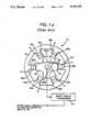
- FIG. 1is a schematic illustration of a conventional SRM drive
- FIG. 2is a graphical illustration of phase flux versus phase current for different values of rotor angle
- FIG. 3is a graphical illustration of ideal phase inductance as a function of rotor angle
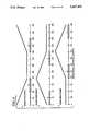
- FIG. 4is a graphical illustration of rotor angle versus phase current for different values of phase flux
- FIG. 5is a graphical illustration of phase inductance versus rotor angle which shows the sensing regions for each respective phase for a three-phase SRM;
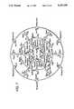
- FIG. 6is a lumped parameter flux/current model useful in determining rotor position in accordance with the method of the present invention
- FIG. 7is the Thevenin equivalent circuit of the model of FIG. 6;
- FIG. 8is a graphical illustration of rotor angle versus alignment for different values of flux.
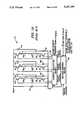
- FIG. 9illustrates a preferred implementation of a rotor position estimator in accordance with the present invention.
- FIG. 1shows a conventional SRM drive configuration.
- SRM 10is illustrated as a three-phase machine with its associated power inverter 12.
- SRM 10includes a rotor 14 rotatable in either a forward or reverse direction within a stationary stator 16.
- Rotor 14has two pairs of diametrically opposite rotor poles 18a-18b and 20a-20b.
- Stator 16has three pairs of diametrically opposite stator poles 22a-22b, 24a-24b and 26a-26b.
- Stator pole windings 28a-28b, 30a-30b and 32a-32b, respectively,are wound on stator pole pairs 22a-22b, 24a-24b and 26a-26b, respectively.
- stator pole windings on each pair of opposing or companion stator pole pairsare connected in series or parallel to form a machine phase winding.
- stator pole windingscomprising each companion pair 28a-28b, 30a-30b and 32a-32b, respectively, are connected in series with each other and with an upper current switching device 33, 34 and 35, respectively, and with a lower current switching device 36, 37 and 38, respectively.
- the upper and lower switching devicesare each illustrated as comprising an insulated gate bipolar transistor (IGT), but other suitable current switching devices may be used; for example, field effect transistors (FET's), gate turn-off thyristors (GTO's), or bipolar junction transistors (BJT's).
- Each phase windingis further coupled to a dc source, such as a battery or a rectified ac source, by flyback or return diodes 45 and 42, 46 and 43, and 47 and 44, respectively.
- a dc sourcesuch as a battery or a rectified ac source
- flyback or return diodes 45 and 42, 46 and 43, and 47 and 44respectively.
- stored magnetic energy in the respective phase windingis returned, through the respective pair of these diodes connected thereto, to the dc source.
- Each series combination of the phase winding with two corresponding switching devices and two flyback diodescomprises one phase leg of inverter 12.
- the inverter phase legsare connected in parallel to each other and are driven by the dc source, which impresses a dc voltage V dc across the parallel inverter phase legs.
- Capacitance 40is provided for filtering transient voltages from the dc source and for supplying ripple current to the inverter.
- a shaft angle transducer 48e.g. an encoder or a resolver, is coupled to rotor 14 for providing rotor angle feedback signals to machine control means 50.
- An operator commandsuch as a torque command, is also generally supplied as an input signal to control means 50.
- Phase current feedback signalsare supplied to a current regulation means 51 which receives phase current feedback signals I A , I B and I C from current sensors 52, 54 and 56.
- Suitable current sensorsare well-known in the art and may comprise, for example, Hall-effect sensors, sensing transformers, sensing transistors, or sensing resistors.
- Control means 50further provides a commanded reference current waveform I REF to current regulation means 51, as described in commonly assigned U.S. Pat. No.
- control meansprovides firing signals to inverter 12 for energizing the machine phase windings in a predetermined sequence, depending upon the particular quadrant of operation.
- phase inductanceas viewed from the stator phase windings is a strong function of rotor position. Specifically, phase inductance ranges from a maximum value L a , corresponding to alignment of rotor poles with the stator poles of the respective phase, to a minimum value L u , corresponding to maximum unalignment of rotor poles with the stator poles of the respective phase.
- FIG. 2graphically illustrates phase flux ⁇ versus magnetomotive force (mmf, in ampere-turns) for different values of rotor angle ⁇ , in electrical degrees.
- mmfmagnetomotive force
- Curve 70which has the steepest initial slope, represents the ⁇ -I curve for the excited phase when the stator poles of that phase are aligned with rotor poles, the rotor angle corresponding thereto being designated as ⁇ a .
- curve 72which has the smallest initial slope, represents the ⁇ -I curve for the excited phase when the stator poles of that phase are at the point of maximum unalignment with rotor poles of the SRM, the rotor angle corresponding thereto being designated as ⁇ u .
- the curves falling between curves 70 and 72represent intermediate inductance values corresponding to varying degrees of rotor and stator pole overlap, with the slopes of the curves monotonically decreasing as the rotor advances from the aligned position to the unaligned position.
- phase inductance Lis a two-valued function of rotor position ⁇ . That is, a given inductance value occurs once as the rotor poles are moving toward alignment with stator poles of a respective phase, and again as the poles are moving away from alignment.
- stator flux linkage ⁇may be measured directly using well-known sensing coils; however, such coils are typically fragile and unreliable. Therefore, under most operating conditions, an accurate determination of phase flux linkage ⁇ can be made by employing the relationship between phase flux linkage ⁇ , phase current I, and phase voltage V according to the following expression: ##EQU1## where r is the phase winding resistance. An estimate of the flux linkage ⁇ can thus be determined from:
- an integrator employed to estimate the flux linkage ⁇can be reset to zero at the end of each cycle, thus avoiding an accumulation of errors.
- suitable sensing regionsare defined by the dashed lines 74.
- the valid sensing regionsrange from 120° before alignment to 60° before alignment, and from 60° after alignment to 120° after alignment.
- the ⁇ -I curvesare separated sufficiently and have easily measurable slopes, so that error sensitivity is minimized.
- FIG. 5graphically illustrates phase inductance L versus rotor angle ⁇ for each phase A, B and C of a three-phase SRM, such as the one illustrated in FIG. 1.
- the cross-hatched rectangular regions in each graphcorrespond to the sensing regions for each respective phase.
- the sensing regions for each phaseextend from 60° after alignment to 120° after alignment, and from 120° before alignment to 60° before alignment. (Additionally, optimal sampling instants in each respective sensing region are indicated by arrows for a discrete implementation of the position estimator of the present invention.)
- FIG. 6shows a lumped parameter flux/current model of a three-phase SRM, such as that of in FIG. 1, which accounts for mutual coupling between the phases thereof in accordance with the present invention.
- the modelcomprises a network mesh of stator, rotor, and air gap reluctance terms.
- the reluctance components of the modelare defined as follows:
- R pc stator pole-to-core reluctancea non-saturable component representing the stator pole and three-dimensional end leakage flux paths
- stator pole-to-pole reluctancea non-saturable component representing the leakage flux path between adjacent stator poles
- R g ( ⁇ ) air gap reluctancea non-saturable component representing the stator-to-rotor air gap flux path, a function of the rotor angle ⁇ relative to alignment
- R t ( ⁇ , ⁇ ) pole tip reluctancea saturable component representing the flux path through both rotor and stator pole tips
- R gt ( ⁇ , ⁇ ) air gap and pole tip reluctancethe sum of R g ( ⁇ ) and R t ( ⁇ , ⁇ )
- R rp ( ⁇ ) rotor pole reluctancea saturable component representing the rotor pole base flux path
- R rc ( ⁇ ) rotor core reluctancea saturable component representing the rotor core flux path
- the saturable componentsare modeled as a function of the local flux density ⁇ as follows: ##EQU2## where A represents the cross sectional area of the flux path, k 1 , k 2 and m are constants which may be determined from laboratory data or finite element modeling of the particular SRM.
- the air gap reluctance R g ( ⁇ )is a periodic function of the angle ⁇ relative to alignment and is modeled as follows: ##EQU3## where ⁇ 1 , ⁇ 2 , and n are constants which may be determined from laboratory data or finite element modeling of the particular SRM.
- the pole-tip reluctance model R t ( ⁇ , ⁇ )is obtained by varying the cross sectional area term as a function of rotor angle according to:
- k 3 -k 6 , p and qare constants, the values of which may be obtained from laboratory data or finite element analysis of the particular SRM.
- the network of FIG. 6is driven by mmf terms F 1 , F 2 and F 3 , corresponding to the ampere-turns applied to each of the respective stator poles.
- the stator pole flux density terms ⁇ 1 , ⁇ 2 and ⁇ 3 resulting from this excitationare determined from phase current and phase flux measurements.
- the phase current and phase flux measurementsare made for each phase simultaneously. Specifically, for each phase i,: ##EQU4## where ⁇ i is determined from measurements of phase voltage and current as described hereinabove with reference to equation (3), and N represents the number of ampere-turns for each respective phase i.
- stator pole reluctances for each phase R spi ( ⁇ i )are evaluated as a function of stator pole flux density ⁇ i .
- the stator pole reluctances R spi ( ⁇ i )are stored as a look-up table in read-only memory (ROM).
- the next step in the indirect rotor position sensing method of the present inventioninvolves replacing the stator pole model of FIG. 6 with a Thevenin equivalent circuit, as shown in FIG. 7 and described according to the following equations: ##EQU5##
- stator core flux densities ⁇ sci.e. between phases i and j, are determined as follows: ##EQU6##
- the stator core reluctancesare stored in ROM as a two-dimensional look-up table. With the stator core reluctances thus determined, the stator pole mmf's F spi are determined from loop equations around the stator periphery; ##EQU7##
- the rotor core reluctancesare stored in ROM as a two-dimensional look-up table.
- FIG. 8is a graph of rotor angle ⁇ versus reluctance for different values of flux density ⁇ . In a preferred embodiment, this graph is stored as a two-dimensional look-up table.
- the sensing phasecan be determined. That is, the sensing phase is the phase operating in one of its predetermined sensing regions.
- the rotor angles of at least one of the remaining phasesare then used to determine whether rotor poles of the SRM are approaching alignment or maximum unalignment with the stator poles of the sensing phase.
- the rotor angles of two phasesare needed to determine the direction of rotation of the motor, since inductance is a two-valued function of rotor angle, as described hereinabove.
- a rotor position estimate ⁇ r for the SRMis determined from: ##EQU11## where i designates the sensing phase, and the sign of ⁇ i depends on the direction of rotation and whether or not the rotor poles are approaching alignment with the stator poles of the sensing phase.
- FIG. 9illustrates a preferred embodiment of a rotor position estimator in accordance with the present invention.
- the phase current for each respective phase I A , I B and I Cis sensed by a suitable current sensor 76 (e.g., a Hall-effect sensor, sensing transformer, or sensing resistor) and the phase winding voltage V A , V B and V C is sensed by a suitable voltage sensor or is otherwise determined by a suitable indirect method for estimating voltage.
- a suitable current sensor 76e.g., a Hall-effect sensor, sensing transformer, or sensing resistor
- Each respective phase currentis provided to a multiplier 84 wherein it is multiplied by the phase winding resistance r, and the result is subtracted from the phase winding voltage V by a summer 86.
- the output signal from summer 86is integrated by an integrator 88 to provide an estimate of the phase flux ⁇ .
- microprocessor 90is employed to make the calculations of equations (9)-(30) based on the phase current and flux measurements and the flux/current model in accordance with the rotor position estimation method of the present invention.
Landscapes
- Engineering & Computer Science (AREA)
- Power Engineering (AREA)
- Control Of Motors That Do Not Use Commutators (AREA)
Abstract
Description
Ψ=LI (1)
Ψ=∫(V-Ir)dt (3)
A(θ)=k.sub.3 +k.sub.4 ∥cos(θ/2)∥.sup.p, (6)
R.sub.t (θ,φ)=k.sub.5 +k.sub.6 ∥(φ,A(θ)∥.sup.q, (7)
φ.sub.r1 =φ.sup.'.sub.1 +φ.sub.pp12 +φ.sub.pp31 (21)
φ.sub.r2 =φ.sup.40 .sub.2 -φ.sub.pp23 +φ.sub.pp12 (22)
φ.sub.r1 =φ.sup.40 .sub.3 +φ.sub.pp31 -φ.sub.pp23 (23)
Claims (8)
Ψ=∫(V-Ir)dt,
Ψ=∫(V-Ir)dt,
Priority Applications (1)
| Application Number | Priority Date | Filing Date | Title |
|---|---|---|---|
| US07/653,371US5107195A (en) | 1991-02-11 | 1991-02-11 | Rotor position estimator for a switched reluctance machine using a lumped parameter flux/current model |
Applications Claiming Priority (1)
| Application Number | Priority Date | Filing Date | Title |
|---|---|---|---|
| US07/653,371US5107195A (en) | 1991-02-11 | 1991-02-11 | Rotor position estimator for a switched reluctance machine using a lumped parameter flux/current model |
Publications (1)
| Publication Number | Publication Date |
|---|---|
| US5107195Atrue US5107195A (en) | 1992-04-21 |
Family
ID=24620589
Family Applications (1)
| Application Number | Title | Priority Date | Filing Date |
|---|---|---|---|
| US07/653,371Expired - LifetimeUS5107195A (en) | 1991-02-11 | 1991-02-11 | Rotor position estimator for a switched reluctance machine using a lumped parameter flux/current model |
Country Status (1)
| Country | Link |
|---|---|
| US (1) | US5107195A (en) |
Cited By (46)
| Publication number | Priority date | Publication date | Assignee | Title |
|---|---|---|---|---|
| US5291115A (en)* | 1992-09-25 | 1994-03-01 | The Texas A&M University System | Method and apparatus for sensing the rotor position of a switched reluctance motor without a shaft position sensor |
| WO1994005077A1 (en)* | 1992-08-21 | 1994-03-03 | British Technology Group Ltd. | Method of and apparatus for determining a rotor displacement parameter |
| US5315224A (en)* | 1989-12-27 | 1994-05-24 | Emotron Aktiebolag | Method and an arrangement for starting an electrical machine having varying reluctance |
| US5325026A (en)* | 1992-06-29 | 1994-06-28 | General Electric Company | Microprocessor-based commutator for electronically commutated motors |
| US5469039A (en)* | 1991-09-25 | 1995-11-21 | Switched Reluctance Drives Limited | Control of switched reluctance machines |
| US5488566A (en)* | 1992-06-02 | 1996-01-30 | Eldec Corporation | Multi-coil impedance |
| US5513539A (en)* | 1994-06-30 | 1996-05-07 | Transalta Utilities Corporation | Apparatus and method for determining the best position for inner and outer members in a rotary machine |
| US5525886A (en)* | 1994-06-23 | 1996-06-11 | General Electric Company | Low speed position estimator for switched reluctance machine using flux/current model |
| US5545964A (en)* | 1992-09-24 | 1996-08-13 | Switched Reluctance Drives Ltd. | Control of switched reluctance machines |
| US5637974A (en)* | 1995-04-21 | 1997-06-10 | Itt Automotive Electrical Systems, Inc. | Method and apparatus for hybrid direct-indirect control of a switched reluctance motor |
| EP0780966A3 (en)* | 1995-12-19 | 1997-10-15 | Switched Reluctance Drives Ltd | Sensorless rotor position monitoring in a reluctance machine |
| US5689165A (en)* | 1996-04-09 | 1997-11-18 | Sundstrand Corporation | Estimator initialization circuit and method for a sensorless switched reluctance machine system |
| US5844385A (en)* | 1996-07-10 | 1998-12-01 | Sundstrand Corporation | Absolute angle estimation apparatus for a sensorless switched reluctance machine system |
| US5859518A (en)* | 1997-12-22 | 1999-01-12 | Micro Linear Corporation | Switched reluctance motor controller with sensorless rotor position detection |
| US5864217A (en)* | 1997-05-08 | 1999-01-26 | General Electric Company | Switched reluctance machine with toothed-wheel rotor sensor |
| US5867004A (en)* | 1996-04-09 | 1999-02-02 | Sundstrand Corporation | Relative angel estimation apparatus for a sensorless switched reluctance machine system |
| US5920175A (en)* | 1996-04-09 | 1999-07-06 | Sundstrand Corporation | Instantaneous position indicating apparatus for a sensorless switched reluctance machine system |
| US6137257A (en)* | 1999-04-30 | 2000-10-24 | Delphi Technologies, Inc. | Method for monitoring the position of a switched reluctance motor |
| US6211633B1 (en) | 1996-07-10 | 2001-04-03 | Hamilton Sundstrand Corporation | Synchronous sampling circuit for a sensorless switching reluctance machine system |
| US6291949B1 (en)* | 1998-12-21 | 2001-09-18 | Switched Reluctance Drives Limited | Control of switched reluctance machines |
| US6328136B1 (en)* | 1997-03-18 | 2001-12-11 | Mitsubishi Denki Kabushiki Kaisha | Drive machine for elevators with drive sheave position detector |
| US6344089B1 (en) | 1977-08-15 | 2002-02-05 | Mitsubishi Denki Kabushiki Kaisha | Drive control for elevator |
| US6349796B1 (en) | 1999-09-17 | 2002-02-26 | Mitsubishi Denki Kabushiki Kaisha | Starting drive control for elevator |
| US6351094B1 (en)* | 1999-02-15 | 2002-02-26 | Switched Reluctance Drives, Ltd. | Control of switched reluctance machines |
| US6359412B1 (en) | 1996-04-09 | 2002-03-19 | Hamilton Sundstrand Corporation | Commutation apparatus and method for a four state sensorless switched reluctance machine system utilizing machine winding current sensing |
| US6396236B1 (en)* | 1998-06-11 | 2002-05-28 | Abb Oy. | Method of minimizing errors in rotor angle estimate in synchronous machine |
| US6448736B1 (en) | 2001-04-16 | 2002-09-10 | Motorola, Inc. | Method for controlling switched reluctance motor, and controller |
| US20030111975A1 (en)* | 2001-12-18 | 2003-06-19 | Switched Reluctance Drives Limited | Rotor position detection of a switched reluctance drive |
| US20040103719A1 (en)* | 2002-04-12 | 2004-06-03 | Abbas Raftari | Diagnostic system and method for an electric motor using torque estimates |
| US20040108826A1 (en)* | 2002-12-10 | 2004-06-10 | Emerson Electric Co. | Method for characterizing a rotating electromagnetic machine |
| US20040134267A1 (en)* | 2002-04-12 | 2004-07-15 | Mathew Boesch | Diagnostic system and method for an electric motor using torque estimates |
| US20050062452A1 (en)* | 2002-10-25 | 2005-03-24 | Delphi Technologies, Inc. | Method and apparatus for determining phase current of switched reluctance electric machines |
| US20050275361A1 (en)* | 2004-06-11 | 2005-12-15 | International Rectifier Corporation | Hall sensor alignment for BLDC motor |
| US20060119310A1 (en)* | 2004-12-06 | 2006-06-08 | Kabushiki Kaisha Toyota Jidoshokki | Inverter device |
| US20070069669A1 (en)* | 2005-09-29 | 2007-03-29 | Mackay David K | System and method for starting and operating a motor |
| US20090128074A1 (en)* | 2007-11-16 | 2009-05-21 | Jun Hu | Initial rotor position detection and start-up system for a dynamoelectric machine |
| US20110062909A1 (en)* | 2009-09-11 | 2011-03-17 | Gm Global Technology Operations, Inc. | Position sensorless control of permanent magnet motors |
| US20110101900A1 (en)* | 2008-07-01 | 2011-05-05 | Schneider Toshiba Inverter Europe Sas | Method for determining the inductances of a permanent magnet synchronous machine |
| CN102608550A (en)* | 2011-01-20 | 2012-07-25 | 株式会社丰田自动织机 | Method for detecting deterioration of permanent magnet in electric motor and system for the method |
| US20130207588A1 (en)* | 2012-02-15 | 2013-08-15 | Samsung Electro-Mechanics Co., Ltd. | Initial driving apparatus and method of two-phase srm |
| CN103401503A (en)* | 2013-07-29 | 2013-11-20 | 清华大学 | Method and device for distinguishing double-three-phase motor parameter on line on harmonic plane |
| US9729088B2 (en) | 2013-04-22 | 2017-08-08 | Nxp Usa, Inc. | Method, computer program product and controller for starting-up a switched reluctance motor, and electrical apparatus implementing same |
| US10193475B2 (en) | 2014-06-25 | 2019-01-29 | Caterpillar Inc. | Sensorless control of switched reluctance machines for low speeds and standstill |
| US10666182B1 (en)* | 2018-04-06 | 2020-05-26 | Caterpillar Inc. | System to control a rotary electric machine |
| CN113688499A (en)* | 2021-07-09 | 2021-11-23 | 西北工业大学 | Three-phase 12/8 pole switched reluctance motor modeling method based on dynamic and static tests |
| US11711034B2 (en) | 2020-12-01 | 2023-07-25 | Kohler Co. | Sensorless position detection for electric machine |
Citations (8)
| Publication number | Priority date | Publication date | Assignee | Title |
|---|---|---|---|---|
| US4584506A (en)* | 1984-11-23 | 1986-04-22 | Polestar Magnetronics Inc. | Reluctance motor with electronically controlled stator windings |
| US4739240A (en)* | 1987-04-29 | 1988-04-19 | General Electric Company | Commutator for switched reluctance drive |
| US4772839A (en)* | 1987-10-27 | 1988-09-20 | General Electric Company | Rotor position estimator for switched reluctance motor |
| US4896089A (en)* | 1989-01-31 | 1990-01-23 | General Electric Company | Fault management system for a switched reluctance motor |
| US4933620A (en)* | 1989-05-09 | 1990-06-12 | General Electric Company | Control system for low speed switched reluctance motor |
| US4959596A (en)* | 1989-04-03 | 1990-09-25 | General Electric Company | Switched reluctance motor drive system and laundering apparatus employing same |
| US4961038A (en)* | 1989-10-16 | 1990-10-02 | General Electric Company | Torque estimator for switched reluctance machines |
| US4990843A (en)* | 1988-06-27 | 1991-02-05 | Electrolux Mecatronik Aktiebolag | Reluctance motor |
- 1991
- 1991-02-11USUS07/653,371patent/US5107195A/ennot_activeExpired - Lifetime
Patent Citations (8)
| Publication number | Priority date | Publication date | Assignee | Title |
|---|---|---|---|---|
| US4584506A (en)* | 1984-11-23 | 1986-04-22 | Polestar Magnetronics Inc. | Reluctance motor with electronically controlled stator windings |
| US4739240A (en)* | 1987-04-29 | 1988-04-19 | General Electric Company | Commutator for switched reluctance drive |
| US4772839A (en)* | 1987-10-27 | 1988-09-20 | General Electric Company | Rotor position estimator for switched reluctance motor |
| US4990843A (en)* | 1988-06-27 | 1991-02-05 | Electrolux Mecatronik Aktiebolag | Reluctance motor |
| US4896089A (en)* | 1989-01-31 | 1990-01-23 | General Electric Company | Fault management system for a switched reluctance motor |
| US4959596A (en)* | 1989-04-03 | 1990-09-25 | General Electric Company | Switched reluctance motor drive system and laundering apparatus employing same |
| US4933620A (en)* | 1989-05-09 | 1990-06-12 | General Electric Company | Control system for low speed switched reluctance motor |
| US4961038A (en)* | 1989-10-16 | 1990-10-02 | General Electric Company | Torque estimator for switched reluctance machines |
Cited By (67)
| Publication number | Priority date | Publication date | Assignee | Title |
|---|---|---|---|---|
| US6344089B1 (en) | 1977-08-15 | 2002-02-05 | Mitsubishi Denki Kabushiki Kaisha | Drive control for elevator |
| US5315224A (en)* | 1989-12-27 | 1994-05-24 | Emotron Aktiebolag | Method and an arrangement for starting an electrical machine having varying reluctance |
| US5469039A (en)* | 1991-09-25 | 1995-11-21 | Switched Reluctance Drives Limited | Control of switched reluctance machines |
| US5488566A (en)* | 1992-06-02 | 1996-01-30 | Eldec Corporation | Multi-coil impedance |
| US5325026A (en)* | 1992-06-29 | 1994-06-28 | General Electric Company | Microprocessor-based commutator for electronically commutated motors |
| GB2284513A (en)* | 1992-08-21 | 1995-06-07 | British Tech Group | Method of and apparatus for determining a rotor displacement parameter |
| US6005364A (en)* | 1992-08-21 | 1999-12-21 | Btg International Limited | Rotor position measurement |
| GB2284513B (en)* | 1992-08-21 | 1997-03-05 | British Tech Group | Method of and apparatus for determining a rotor displacement parameter |
| WO1994005077A1 (en)* | 1992-08-21 | 1994-03-03 | British Technology Group Ltd. | Method of and apparatus for determining a rotor displacement parameter |
| US5545964A (en)* | 1992-09-24 | 1996-08-13 | Switched Reluctance Drives Ltd. | Control of switched reluctance machines |
| US5563488A (en)* | 1992-09-24 | 1996-10-08 | Switched Reluctance Drives Limited | Control of switched reluctance machines |
| US5410235A (en)* | 1992-09-25 | 1995-04-25 | The Texas A&M University System | Method and apparatus for sensing the rotor position of a switched reluctance motor |
| WO1994008390A1 (en)* | 1992-09-25 | 1994-04-14 | The Texas A&M University System | Sensing of rotor position of a switched reluctance motor without a shaft position sensor |
| US5291115A (en)* | 1992-09-25 | 1994-03-01 | The Texas A&M University System | Method and apparatus for sensing the rotor position of a switched reluctance motor without a shaft position sensor |
| US5525886A (en)* | 1994-06-23 | 1996-06-11 | General Electric Company | Low speed position estimator for switched reluctance machine using flux/current model |
| US5513539A (en)* | 1994-06-30 | 1996-05-07 | Transalta Utilities Corporation | Apparatus and method for determining the best position for inner and outer members in a rotary machine |
| US5637974A (en)* | 1995-04-21 | 1997-06-10 | Itt Automotive Electrical Systems, Inc. | Method and apparatus for hybrid direct-indirect control of a switched reluctance motor |
| US5793179A (en)* | 1995-12-19 | 1998-08-11 | Switched Reluctance Drives Limited | Sensorless rotor position monitoring in reluctance machines |
| EP0780966A3 (en)* | 1995-12-19 | 1997-10-15 | Switched Reluctance Drives Ltd | Sensorless rotor position monitoring in a reluctance machine |
| US5867004A (en)* | 1996-04-09 | 1999-02-02 | Sundstrand Corporation | Relative angel estimation apparatus for a sensorless switched reluctance machine system |
| US5920175A (en)* | 1996-04-09 | 1999-07-06 | Sundstrand Corporation | Instantaneous position indicating apparatus for a sensorless switched reluctance machine system |
| US5689165A (en)* | 1996-04-09 | 1997-11-18 | Sundstrand Corporation | Estimator initialization circuit and method for a sensorless switched reluctance machine system |
| US6359412B1 (en) | 1996-04-09 | 2002-03-19 | Hamilton Sundstrand Corporation | Commutation apparatus and method for a four state sensorless switched reluctance machine system utilizing machine winding current sensing |
| US5844385A (en)* | 1996-07-10 | 1998-12-01 | Sundstrand Corporation | Absolute angle estimation apparatus for a sensorless switched reluctance machine system |
| US6211633B1 (en) | 1996-07-10 | 2001-04-03 | Hamilton Sundstrand Corporation | Synchronous sampling circuit for a sensorless switching reluctance machine system |
| US6328136B1 (en)* | 1997-03-18 | 2001-12-11 | Mitsubishi Denki Kabushiki Kaisha | Drive machine for elevators with drive sheave position detector |
| US5864217A (en)* | 1997-05-08 | 1999-01-26 | General Electric Company | Switched reluctance machine with toothed-wheel rotor sensor |
| US5859518A (en)* | 1997-12-22 | 1999-01-12 | Micro Linear Corporation | Switched reluctance motor controller with sensorless rotor position detection |
| US6396236B1 (en)* | 1998-06-11 | 2002-05-28 | Abb Oy. | Method of minimizing errors in rotor angle estimate in synchronous machine |
| US6291949B1 (en)* | 1998-12-21 | 2001-09-18 | Switched Reluctance Drives Limited | Control of switched reluctance machines |
| US6351094B1 (en)* | 1999-02-15 | 2002-02-26 | Switched Reluctance Drives, Ltd. | Control of switched reluctance machines |
| US6137257A (en)* | 1999-04-30 | 2000-10-24 | Delphi Technologies, Inc. | Method for monitoring the position of a switched reluctance motor |
| US6349796B1 (en) | 1999-09-17 | 2002-02-26 | Mitsubishi Denki Kabushiki Kaisha | Starting drive control for elevator |
| US6448736B1 (en) | 2001-04-16 | 2002-09-10 | Motorola, Inc. | Method for controlling switched reluctance motor, and controller |
| US6853163B2 (en)* | 2001-12-18 | 2005-02-08 | Switched Reluctance Drives Ltd. | Rotor position detection of a switched reluctance drive |
| US20030111975A1 (en)* | 2001-12-18 | 2003-06-19 | Switched Reluctance Drives Limited | Rotor position detection of a switched reluctance drive |
| US20040103719A1 (en)* | 2002-04-12 | 2004-06-03 | Abbas Raftari | Diagnostic system and method for an electric motor using torque estimates |
| US20040134267A1 (en)* | 2002-04-12 | 2004-07-15 | Mathew Boesch | Diagnostic system and method for an electric motor using torque estimates |
| US7116068B2 (en) | 2002-04-12 | 2006-10-03 | Ford Global Technologies, Llc | Diagnostic system and method for an electric motor using torque estimates |
| US7116077B2 (en) | 2002-04-12 | 2006-10-03 | Ford Global Technologies, Llc | Diagnostic system and method for an electric motor using torque estimates |
| US20050062452A1 (en)* | 2002-10-25 | 2005-03-24 | Delphi Technologies, Inc. | Method and apparatus for determining phase current of switched reluctance electric machines |
| US20040108826A1 (en)* | 2002-12-10 | 2004-06-10 | Emerson Electric Co. | Method for characterizing a rotating electromagnetic machine |
| US7423396B2 (en)* | 2004-06-11 | 2008-09-09 | International Rectifier Corporation | Hall sensor alignment for BLDC motor |
| US20050275361A1 (en)* | 2004-06-11 | 2005-12-15 | International Rectifier Corporation | Hall sensor alignment for BLDC motor |
| CN100423443C (en)* | 2004-12-06 | 2008-10-01 | 株式会社丰田自动织机 | Inverter device |
| US7202618B2 (en)* | 2004-12-06 | 2007-04-10 | Kabushiki Kaisha Toyota Jidoshokki | Inverter device |
| US20060119310A1 (en)* | 2004-12-06 | 2006-06-08 | Kabushiki Kaisha Toyota Jidoshokki | Inverter device |
| US20070069669A1 (en)* | 2005-09-29 | 2007-03-29 | Mackay David K | System and method for starting and operating a motor |
| US7592761B2 (en)* | 2005-09-29 | 2009-09-22 | Agile Systems Inc. | System and method for starting and operating a motor |
| US20090128074A1 (en)* | 2007-11-16 | 2009-05-21 | Jun Hu | Initial rotor position detection and start-up system for a dynamoelectric machine |
| US9160264B2 (en) | 2007-11-16 | 2015-10-13 | Hamilton Sundstrand Corporation | Initial rotor position detection and start-up system for a dynamoelectric machine |
| US8519650B2 (en)* | 2008-07-01 | 2013-08-27 | Schneider Toshiba Inverter Europe Sas | Method for determining the inductances of a permanent magnet synchronous machine |
| US20110101900A1 (en)* | 2008-07-01 | 2011-05-05 | Schneider Toshiba Inverter Europe Sas | Method for determining the inductances of a permanent magnet synchronous machine |
| CN102025306B (en)* | 2009-09-11 | 2013-06-12 | 通用汽车环球科技运作公司 | Position sensorless control of permanent magnet motors |
| US8310189B2 (en)* | 2009-09-11 | 2012-11-13 | GM Global Technology Operations LLC | Position sensorless control of permanent magnet motors |
| CN102025306A (en)* | 2009-09-11 | 2011-04-20 | 通用汽车环球科技运作公司 | Position sensorless control of permanent magnet motors |
| US20110062909A1 (en)* | 2009-09-11 | 2011-03-17 | Gm Global Technology Operations, Inc. | Position sensorless control of permanent magnet motors |
| CN102608550A (en)* | 2011-01-20 | 2012-07-25 | 株式会社丰田自动织机 | Method for detecting deterioration of permanent magnet in electric motor and system for the method |
| US20130207588A1 (en)* | 2012-02-15 | 2013-08-15 | Samsung Electro-Mechanics Co., Ltd. | Initial driving apparatus and method of two-phase srm |
| US9729088B2 (en) | 2013-04-22 | 2017-08-08 | Nxp Usa, Inc. | Method, computer program product and controller for starting-up a switched reluctance motor, and electrical apparatus implementing same |
| CN103401503B (en)* | 2013-07-29 | 2016-05-11 | 清华大学 | A kind of method and device in harmonic wave plane on-line identification double three-phase machine parameter |
| CN103401503A (en)* | 2013-07-29 | 2013-11-20 | 清华大学 | Method and device for distinguishing double-three-phase motor parameter on line on harmonic plane |
| US10193475B2 (en) | 2014-06-25 | 2019-01-29 | Caterpillar Inc. | Sensorless control of switched reluctance machines for low speeds and standstill |
| US10666182B1 (en)* | 2018-04-06 | 2020-05-26 | Caterpillar Inc. | System to control a rotary electric machine |
| US11711034B2 (en) | 2020-12-01 | 2023-07-25 | Kohler Co. | Sensorless position detection for electric machine |
| CN113688499A (en)* | 2021-07-09 | 2021-11-23 | 西北工业大学 | Three-phase 12/8 pole switched reluctance motor modeling method based on dynamic and static tests |
| CN113688499B (en)* | 2021-07-09 | 2024-02-27 | 西北工业大学 | Modeling method of three-phase 12/8-pole switch reluctance motor based on dynamic and static test |
Similar Documents
| Publication | Publication Date | Title |
|---|---|---|
| US5107195A (en) | Rotor position estimator for a switched reluctance machine using a lumped parameter flux/current model | |
| US5097190A (en) | Rotor position estimator for a switched reluctance machine | |
| US5140243A (en) | Discrete position estimator for a switched reluctance machine using a flux-current map comparator | |
| US5525886A (en) | Low speed position estimator for switched reluctance machine using flux/current model | |
| US5140244A (en) | Lock detector for switched reluctance machine rotor position estimator | |
| US4961038A (en) | Torque estimator for switched reluctance machines | |
| Haque et al. | A sensorless initial rotor position estimation scheme for a direct torque controlled interior permanent magnet synchronous motor drive | |
| Bateman et al. | Sensorless operation of an ultra-high-speed switched reluctance machine | |
| Batzel et al. | Slotless permanent magnet synchronous motor operation without a high resolution rotor angle sensor | |
| Bu et al. | Eliminating starting hesitation for reliable sensorless control of switched reluctance motors | |
| KR100665075B1 (en) | Brushless machine controls, systems and methods | |
| US8294401B2 (en) | Control of electrical machines | |
| JPH06113585A (en) | Position detection device for brushless dc motor using time-difference method without hall-effect device | |
| CN101262196A (en) | Method for detecting rotor position of brushless DC motor without position sensor | |
| Panada et al. | Analysis of the waveform-detection technique for indirect roto-position sensing of switched reluctance motor drives | |
| US7288915B2 (en) | Rotor position detection of an electrical machine | |
| JP4472083B2 (en) | Rotor position detection in a switched reluctance machine | |
| JP3397013B2 (en) | Control device for synchronous motor | |
| EP1109308A2 (en) | Brushless machine control | |
| Ehsani et al. | Rotor position sensing in switched reluctance motor drives by measuring mutually induced voltages | |
| US7067997B2 (en) | Method for determining rotor position angle of synchronous machine | |
| Colby | Classification of inverter driven permanent magnet synchronous motors | |
| US20060052976A1 (en) | Claw-pole electric machine with actively controlled switches | |
| Lee et al. | Sensorless commutation techniques for brushless permanent-magnet and reluctance motor drives | |
| Batzel et al. | Starting method for sensorless operation of slotless permanent magnet synchronous machines |
Legal Events
| Date | Code | Title | Description |
|---|---|---|---|
| AS | Assignment | Owner name:GENERAL ELECTRIC COMPANY, A NY CORP., NEW YORK Free format text:ASSIGNMENT OF ASSIGNORS INTEREST.;ASSIGNORS:LYONS, JAMES P.;MACMINN, STEPHEN R.;PRESTON, MARK A.;REEL/FRAME:005606/0726 Effective date:19910204 | |
| FEPP | Fee payment procedure | Free format text:PAYOR NUMBER ASSIGNED (ORIGINAL EVENT CODE: ASPN); ENTITY STATUS OF PATENT OWNER: LARGE ENTITY | |
| STCF | Information on status: patent grant | Free format text:PATENTED CASE | |
| FEPP | Fee payment procedure | Free format text:PAYOR NUMBER ASSIGNED (ORIGINAL EVENT CODE: ASPN); ENTITY STATUS OF PATENT OWNER: LARGE ENTITY Free format text:PAYER NUMBER DE-ASSIGNED (ORIGINAL EVENT CODE: RMPN); ENTITY STATUS OF PATENT OWNER: LARGE ENTITY | |
| FEPP | Fee payment procedure | Free format text:PAYER NUMBER DE-ASSIGNED (ORIGINAL EVENT CODE: RMPN); ENTITY STATUS OF PATENT OWNER: LARGE ENTITY Free format text:PAYOR NUMBER ASSIGNED (ORIGINAL EVENT CODE: ASPN); ENTITY STATUS OF PATENT OWNER: LARGE ENTITY | |
| FPAY | Fee payment | Year of fee payment:4 | |
| FPAY | Fee payment | Year of fee payment:8 | |
| FPAY | Fee payment | Year of fee payment:12 |