US5105983A - Infusion apparatus - Google Patents
Infusion apparatusDownload PDFInfo
- Publication number
- US5105983A US5105983AUS07/429,313US42931389AUS5105983AUS 5105983 AUS5105983 AUS 5105983AUS 42931389 AUS42931389 AUS 42931389AUS 5105983 AUS5105983 AUS 5105983A
- Authority
- US
- United States
- Prior art keywords
- liquid
- reservoir
- chamber
- dispensing
- pressure
- Prior art date
- Legal status (The legal status is an assumption and is not a legal conclusion. Google has not performed a legal analysis and makes no representation as to the accuracy of the status listed.)
- Expired - Lifetime
Links
- 238000001802infusionMethods0.000titleabstractdescription10
- 239000007788liquidSubstances0.000claimsabstractdescription69
- 230000000295complement effectEffects0.000claimsdescription4
- 239000004033plasticSubstances0.000claimsdescription3
- 229920003023plasticPolymers0.000claimsdescription3
- 239000000463materialSubstances0.000claims2
- 239000012528membraneSubstances0.000description9
- 230000008878couplingEffects0.000description5
- 238000010168coupling processMethods0.000description5
- 238000005859coupling reactionMethods0.000description5
- 239000003814drugSubstances0.000description5
- 229940079593drugDrugs0.000description5
- 238000010276constructionMethods0.000description4
- 239000000945fillerSubstances0.000description3
- 239000012530fluidSubstances0.000description3
- 238000002347injectionMethods0.000description3
- 239000007924injectionSubstances0.000description3
- 238000001990intravenous administrationMethods0.000description3
- 230000004048modificationEffects0.000description3
- 238000012986modificationMethods0.000description3
- 238000013459approachMethods0.000description2
- 230000007423decreaseEffects0.000description2
- 229920000126latexPolymers0.000description2
- 230000000717retained effectEffects0.000description2
- 125000000391vinyl groupChemical group[H]C([*])=C([H])[H]0.000description2
- 229920002554vinyl polymerPolymers0.000description2
- 230000002159abnormal effectEffects0.000description1
- 230000004308accommodationEffects0.000description1
- 239000011324beadSubstances0.000description1
- 238000004891communicationMethods0.000description1
- 230000000694effectsEffects0.000description1
- 239000013013elastic materialSubstances0.000description1
- 239000003978infusion fluidSubstances0.000description1
- 238000010253intravenous injectionMethods0.000description1
- 239000004816latexSubstances0.000description1
- 230000002093peripheral effectEffects0.000description1
- 230000003014reinforcing effectEffects0.000description1
- 239000002356single layerSubstances0.000description1
Images


Classifications
- A—HUMAN NECESSITIES
- A61—MEDICAL OR VETERINARY SCIENCE; HYGIENE
- A61M—DEVICES FOR INTRODUCING MEDIA INTO, OR ONTO, THE BODY; DEVICES FOR TRANSDUCING BODY MEDIA OR FOR TAKING MEDIA FROM THE BODY; DEVICES FOR PRODUCING OR ENDING SLEEP OR STUPOR
- A61M5/00—Devices for bringing media into the body in a subcutaneous, intra-vascular or intramuscular way; Accessories therefor, e.g. filling or cleaning devices, arm-rests
- A61M5/14—Infusion devices, e.g. infusing by gravity; Blood infusion; Accessories therefor
- A61M5/142—Pressure infusion, e.g. using pumps
- A61M5/145—Pressure infusion, e.g. using pumps using pressurised reservoirs, e.g. pressurised by means of pistons
- A61M5/148—Pressure infusion, e.g. using pumps using pressurised reservoirs, e.g. pressurised by means of pistons flexible, e.g. independent bags
- A61M5/152—Pressure infusion, e.g. using pumps using pressurised reservoirs, e.g. pressurised by means of pistons flexible, e.g. independent bags pressurised by contraction of elastic reservoirs
- A—HUMAN NECESSITIES
- A61—MEDICAL OR VETERINARY SCIENCE; HYGIENE
- A61M—DEVICES FOR INTRODUCING MEDIA INTO, OR ONTO, THE BODY; DEVICES FOR TRANSDUCING BODY MEDIA OR FOR TAKING MEDIA FROM THE BODY; DEVICES FOR PRODUCING OR ENDING SLEEP OR STUPOR
- A61M2209/00—Ancillary equipment
- A61M2209/04—Tools for specific apparatus
- A61M2209/045—Tools for specific apparatus for filling, e.g. for filling reservoirs
Definitions
- the present inventionrelates to liquid dispensing apparatus and pertains particularly to an improved infusor apparatus for delivering intravenous drugs at a controlled rate to a patient.
- the prior art devicestypically comprise an elastic bladder forming a liquid container mounted in an elongated cylindrical housing, and having a flow control valve or device and tubing for supply of the liquid to the patient.
- the elastic walls of the bladderexpand along the walls of the cylindrical housing when filled with the liquid, and provide the pressure for expelling the liquid.
- These prior art devicesare typically filled by hand by means of a syringe which often require an inordinate amount of force.
- the pressure and flow ratebe reasonably constant over the infusion period. It is also desirable that no abnormal pressures occur during the infusion.
- a liquid infusor apparatuscomprises an elastic reservoir mounted within a spherical chamber and enabled to expand naturally at a constant pressure.
- Another embodimentcomprises a holding reservoir that may be pre-filled, and a pressure reservoir that is loaded from the holding reservoir preparatory to infusion.
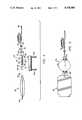
- FIG. 1is a perspective view of a housing assembly of a preferred embodiment of the invention
- FIG. 2is a top plan view of the embodiment of FIG. 1;
- FIG. 3is a view taken generally on line 3--3 of FIG. 2;
- FIG. 4is an exploded view of the reservoir and nozzle assembly of the embodiment of FIG. 1;
- FIG. 5is a top plan view of the assembled components of FIG. 4;
- FIG. 6is a perspective exploded view of an alternate embodiment of the invention.
- FIG. 7is a top plan view of the embodiment of FIG. 6;
- FIG. 8is a section view taken generally along line 8--8 of FIG. 7;
- FIG. 9is a perspective exploded view of a further embodiment of the invention.
- FIG. 10is a side elevation view in section of the infusion pump of the embodiment of FIG. 9.
- FIG. 11is a view like FIG. 10 of a further modification of the embodiment of FIG. 10.
- the illustrated housingcomprises a pair of complementary half-shell like housings comprising essentially an upper housing 12 and a lower housing 14, hinged together at rear pivot axis by means of a built-in hinge pin 16 of the lower housing, and a U-shaped hinge journal 18 of the upper housing 12.
- the housingsare essentially identical except for the hinge construction, and that the upper housing is constructed in the preferred form to fit within the inside of a peripheral rim 20 of the lower housing having a similar like rim 22.
- the housingis preferably formed of a lightweight substantially rigid plastic, and formed to have a plurality of longitudinal reinforcing ribs 24 and 26 for the upper and lower housings.
- the housingsfit together and form what can be considered a first or low volume cavity or chamber 30 between opposed surfaces 32 and 34, and a second high volume cavity or chamber 36 between upper semi-spherical surface 38 and lower semi-spherical surface 40.
- the housingis thus designed to accommodate a holding reservoir and a pressure reservoir as will be explained.
- the upper housinghas recesses or cavities 42 and 44, with the lower housing having similar recesses or cavities 46 and 48 for accommodating the ends of a combination support and flow control unit, as shown in FIGS. 4 and 5, and as will be explained.
- Each housingis also provided with semi-circular cut-outs 50 and 52 at the forward end thereof for accommodating the forward or outlet end of the flow control unit.
- a holding reservoir 54comprises a generally flat one-hundred ten milliliter vinyl bag of a construction substantially like that of a typical I.V. bag. This includes a neck with an outlet port or opening 58 for attachment to a filler port of a pressure reservoir as will be explained.
- a bead or the like 60 on the tail end of the bagextends outside the space at the hinge of the housing to hold the bag in place in the chamber 30.
- An elongated elastomeric membrane or tube 62fits over and is clamped over an elongated generally cylindrical support member, designated generally by the numeral 64, which contains a one-way valve and the necessary flow control elements or implements.
- the elastomeric tube 62is designed to form a pressure reservoir, and when pressurized, to inflate in a generally spherical configuration to fit within the spherical cavity 36 of the housing 10.
- the support member 64includes a pair of end clamping surfaces 66 and 68, with adjacent annular shoulders 70 and 72 separating the clamping surfaces from the central nozzle assembly.
- the central section of the support memberincludes a pressure damper, which comprises a generally cylindrical section 74 having a hinged lever or portion 76 formed by a slit 78, leaving a hinge portion or member 80.
- An elastomeric member 82is positioned between the members 74 and 76 to bias against the final collapse of the elastomeric sleeve against lever 76, to eliminate a spike in pressure in situations where the elastomeric sleeve may be pre-stressed or stretched onto the support member.
- the entire assemblyhas an inlet or fill port 84, which communicates by way of a passageway to a port 86 beneath an elastic band 88, forming a one-way valve for filling the elastic of pressure reservoir assembly.
- An outlet port 90communicates by way of a passage in the support member 64 to an outlet port at 92 for connection and communication by way of tubing 94, which may include a filter 96 and orifice and cap assembly 98.
- the elastomeric tube 62is preferably slide or slip fitted on the support member 64 between surfaces 66 and 68, and clamped in place by means of clamps 100 and 102.
- the member 62is preferably slip fitted somewhat loosely with about one-thousandths (0.001) of an inch on support member 64, and not stretched either radially or longitudinally.
- the sleeveis constructed and mounted to accordion fold or roll a slight amount at both ends, as shown in FIGS. 10 and 11, to accommodate elongation when it is inflated.
- This slip or non-pressure fit of the elastomeric sleeve on the support memberprovides a naturally substantially uniformly expanding elastic pressure reservoir. It also eliminates a pressure spike as the reservoir approaches the near empty state in the discharge mode. This non-stressed fit also eliminates the need for the pressure damper previously described, elements 76-82.
- the assemblyis assembled as shown in FIG. 5 and placed within the housing of FIG. 1, with the housing in the partially open position as shown in FIG. 1.
- a pharmacistselects a predetermined quantity of a liquid medication to be administered, and loads it via port 84 into the holding reservoir.
- the liquidflows past the one-way valve 88 from port 86, and flows into the space 78 and into the bag 54 by way of port 104. This fills the bag 54 as illustrated in FIG. 4.
- hemay select pre-filled bags of medication.
- the outer housingis retained in its partially opened position, as shown in FIG. 1, until it is desired to pressurize the liquid for administration.
- the housing 10is closed by pressing the upper housing 12 and the lower housing 14 together, with the housing locking into the closed position. This action, as can be seen in FIG. 3, forces all liquid from the holding reservoir 54 into the pressure reservoir 62, which expands into a spherical configuration within the chamber 36.
- the elastic sleevein its preferred slip fit mode, applies an essentially constant pressure over its range back to its relaxed or empty state.
- This expanded or inflated elastic sleevepressurizes the liquid, which then flows via port 90 along passage 78 and by way of outlet 92 along the tube 94 into the patient.
- the elastic bladder 62continues to apply a pressure to the liquid, forcing it to flow via the orifices and passage for injection into the bloodstream of the patient.
- the member 76yields under the pressure of the elastomeric member 62 by compressing elastomeric member 82, thus preventing a spike in pressure on the last quantity of fluid ejected from the elastic pressured system.
- FIGS. 6-9an alternate more compact embodiment is illustrated wherein overall pump unit is of a generally flat rectangular configuration.
- the overall assemblyis illustrated in a perspective exploded view, showing upper and lower complementary half housings 106 and 108 of a somewhat similar construction as the prior embodiment, with a hinge assembly formed of a hinge journal 110 on the upper member, and a hinge pin 112 on the lower housing member.
- the upper and lower housingswhen assembled together, form a low or essentially no volume chamber 114 between upper and lower planar faces 116 and 118 as in the prior embodiment for receiving a flexible holding reservoir.
- An adjacent larger or higher volume chamber 120is formed between an upper cavity 122 and a lower cavity 124 for receiving an elastic or pressure reservoir.
- a housinghaving first and second chambers for receiving a bladder assembly substantially as in the prior embodiment.
- a flat rectangular 110 ml. holding reservoiris formed by a 110 ml. vinyl bag 126, having a retainer strip or fold 128 as in the prior embodiment.
- An elastic or elastomeric tubular membrane 130is connected at one end 132 to the neck of the bag 126.
- a generally flat rectangular mandrel member 134having a generally flat rectangular configuration, extends into the elastomeric tube 130 to aid in forming the bladder in its desired configuration, as well as voiding it to a zero volume, such that all liquid medication is expelled therefrom.
- a valve assemblyis formed, including a nozzle assembly with a fill port 140 for filling the holding reservoir, and a dispensing nozzle 142 to which the disposable I.V. tubes, as in the prior embodiment, are connected.
- the pressure chamber formed by elastomeric member 130is preferably shaped and configured to expand substantially uniformly within the chamber 120, such that a substantially uniform pressure is applied to the liquid over the length of the injection.
- a tubular elastic membranetends to expand into a substantially spherical configuration. However, it has been determined that it can be preformed and shaped to substantially expand somewhat uniformly to conform to when guided by the generally rectangular cavity or chamber, as illustrated. This configuration provides a desirable compact configuration. However, a more uniform pressure on the liquid medication over the injection range is desirable.
- FIGS. 9 and 10there is illustrated a still further embodiment of the infusor pump assembly, wherein the infusor pump is separable from the charging or filler pump. Moreover, it may be filled by any suitable means, such as a syringe or any other pressurizing means.
- an infusor pump substantially like the previous embodiment, particularly the pump of FIG. 1,is designated generally by the numeral 144 and comprises an outer spherical housing of a size to accommodate the necessary volume of intravenous fluid to be pumped.
- the housing 146has a spherical configuration and is provided with coaxial, or more particularly aligned bores or ports 148 and 150, in which is mounted a bladder assembly comprising an elongated latex rubber elastic sleeve 152 mounted on an elongated central cylindrical support member 154.
- the central support memberis preferably of a generally cylindrical configuration, and includes an inlet port 156 communicating by means of a passage 158 including a one-way valve 159, with the interior of the membrane 152. Any suitable check valve may be used to permit uncoupling of the filling unit without leakage of fluid from the pressurized bladder.
- An outlet passage 160communicates via an outlet port and suitable valve and coupling assembly 162, with an intravenous feeding tube 164.
- the outlet coupling and valve assemblyis preferably the well known type known as a luer lock.
- the luer lockhas a valve that closes the outlet port when the outlet line 164 is uncoupled therefrom.
- the couplingis effective to open the outlet valve when coupled to the outlet fitting.
- Such luer locksare well known off-the-shelf items for I.V. delivery systems.
- the latex tube or membrane 152is mounted on the cylindrical support member 154 preferably in a slightly snug but un-stretched radial fit, and essentially relaxed elongated or non-stretched longitudinal fit.
- the elastic sleevepreferably has what shall be called a slip fit on the support member. This slip fit is preferably with a clearance of on the order of about one-thousandths of an inch of the sleeve on the support. This provides a non-stretched fit with essentially zero volume of the pressure chamber when in the non-stretched or totally relaxed mode.
- the ends of the elastic sleeveare sealingly clamped or secured to the support member, such as by means of suitable clamps or O-rings 168 and 170. These may extend to and cooperate with clamp sleeves 172 having a radial flange 174 and 176 having a radial flange 178.
- the clamp sleeves 172 and 176may be used to position and mount the support member 154 in
- the pressure applied by the pressure chamberwill be substantially a function of the thickness of the wall of the elastic sleeve.
- a typical two to three (2-3) psimay be obtained by a wall thickness of about eighteen to twenty-thousandths (0.018-0.020) of an inch.
- a multi-layered sleeve configurationhas been found to be preferred.
- a plurality of sleeves (two illustrated) 152 and 202are slip fitted (non-stretched) on the support member.
- the inner sleeve 152is slip fitted on the support member 154
- a second sleeve 202is slip fitted over the first sleeve 152.
- Theseare shown in the full or fully inflated condition and inflated in phantom. These multiple layers have been found to be superior to the use of thicker membranes to obtain higher pressures.
- the multiple sleeveswill roll or fold over at the ends, as illustrated, and like the single layer as illustrated in FIG. 10. Thus, to double the pressure, two sleeves of the same thickness are used.
- the elastic sleeve membrane 152When being filled, the elastic sleeve membrane 152 has a tendency to elongate, but expands into a spherical configuration (FIGS. 10 and 11).
- the sleeveis shown in the partially filled position in FIG. 10 and in the fully filled position in phantom.
- the elongationis accommodated in this pump configuration by an accordion effect at the ends of the tube, as shown in phantom, wherein the tube rolls over the ends thereof and inward along the support member 154 as it expands outward to fill the housing 146.
- the accommodation of the elastic membrane in the spherical configurationenables it to expand and contract in its natural fashion, and to maintain a substantially constant pressure and thereby pump rate over the intravenous injection period.
- the layered or multiple sleeve configuration(FIG. 11) has been found to better accommodate the accordion fold and maintain a more uniform pressure than a thicker sleeve.
- the tubular elastic membranesare selected and mounted on the support member in a manner that enables them to roll or fold over at the ends when being filled.
- the entire assemblyincludes a fill pump, which as shown in FIG. 9, comprises an elongated cylindrical collapsible tube 180 capable of springing back to its original shape, with enough force to draw fluid from a supply bag 182, preferably of a typical construction.
- a fill pumpwhich as shown in FIG. 9, comprises an elongated cylindrical collapsible tube 180 capable of springing back to its original shape, with enough force to draw fluid from a supply bag 182, preferably of a typical construction.
- the pumphas a suitable inlet check valve and coupling 184 at the inlet end, and an outlet valve and coupling 186 at the outlet end connected to a filler tube 188 coupled to the inlet port of the infusor pump 144.
- a pump actuator for the assemblyincludes a base plate 190 of a generally rectangular configuration, with a semi-cylindrical recess 192 for receiving the tube member 180.
- a hand actuated lever member 194includes a semi-cylindrical surface 196 complementary to the recess 192. The lever member 194 is pivotably connected at one end by suitable pins 198 to hinge members 200 at each side of the plate assembly.
- This assemblyforms a convenient fill apparatus for a pharmacist to use to fill the infusor pump 146.
- the housing of the pump 146prevents its overfilling, and the fill pump assembly is an example of a simple and inexpensive apparatus for filling the infusor pump.
- FIG. 1could be utilized with this disconnect infusion pump of FIGS. 9 and 10, instead of the separate pump 180 with actuator 190-200.
- the bag 182could be sized to precisely fill the unit 144, which could be accommodated in the spherical chamber 12.
- the unit 10would be made to open to enable removal of the infusor 144 if desired. It could also be retained in the housing as in the FIG. 1 embodiment.
Landscapes
- Health & Medical Sciences (AREA)
- Vascular Medicine (AREA)
- Engineering & Computer Science (AREA)
- Anesthesiology (AREA)
- Biomedical Technology (AREA)
- Heart & Thoracic Surgery (AREA)
- Hematology (AREA)
- Life Sciences & Earth Sciences (AREA)
- Animal Behavior & Ethology (AREA)
- General Health & Medical Sciences (AREA)
- Public Health (AREA)
- Veterinary Medicine (AREA)
- Infusion, Injection, And Reservoir Apparatuses (AREA)
Abstract
Description
Claims (16)
Priority Applications (7)
| Application Number | Priority Date | Filing Date | Title |
|---|---|---|---|
| US07/429,313US5105983A (en) | 1989-10-31 | 1989-10-31 | Infusion apparatus |
| US07/492,982US5080652A (en) | 1989-10-31 | 1990-03-12 | Infusion apparatus |
| JP2256770AJPH03170163A (en) | 1989-10-31 | 1990-09-25 | Device for administering blood under pressure |
| AT90311152TATE122903T1 (en) | 1989-10-31 | 1990-10-11 | INFUSION DEVICE. |
| EP90311152AEP0426319B1 (en) | 1989-10-31 | 1990-10-11 | Infusion apparatus |
| DE69019673TDE69019673T2 (en) | 1989-10-31 | 1990-10-11 | Infusion device. |
| ES90311152TES2075165T3 (en) | 1989-10-31 | 1990-10-11 | INFUSION DEVICE. |
Applications Claiming Priority (1)
| Application Number | Priority Date | Filing Date | Title |
|---|---|---|---|
| US07/429,313US5105983A (en) | 1989-10-31 | 1989-10-31 | Infusion apparatus |
Related Child Applications (1)
| Application Number | Title | Priority Date | Filing Date |
|---|---|---|---|
| US07/492,982Continuation-In-PartUS5080652A (en) | 1989-10-31 | 1990-03-12 | Infusion apparatus |
Publications (1)
| Publication Number | Publication Date |
|---|---|
| US5105983Atrue US5105983A (en) | 1992-04-21 |
Family
ID=23702707
Family Applications (1)
| Application Number | Title | Priority Date | Filing Date |
|---|---|---|---|
| US07/429,313Expired - LifetimeUS5105983A (en) | 1989-10-31 | 1989-10-31 | Infusion apparatus |
Country Status (1)
| Country | Link |
|---|---|
| US (1) | US5105983A (en) |
Cited By (66)
| Publication number | Priority date | Publication date | Assignee | Title |
|---|---|---|---|---|
| US5284481A (en)* | 1992-12-02 | 1994-02-08 | Block Medical, Inc. | Compact collapsible infusion apparatus |
| US5330431A (en)* | 1993-03-12 | 1994-07-19 | Glenn Herskowitz | Infusion pump |
| US5380287A (en)* | 1992-07-31 | 1995-01-10 | Nissho Corporation | Medical solution delivery system |
| US5460490A (en)* | 1994-05-19 | 1995-10-24 | Linvatec Corporation | Multi-purpose irrigation/aspiration pump system |
| US5671884A (en)* | 1995-07-31 | 1997-09-30 | D.B. Smith & Co., Inc. | Backpack sprayer with an expandable accumulator chamber |
| US6056522A (en)* | 1998-05-13 | 2000-05-02 | Sims Deltec, Inc. | Reusable cassette with a moveable door |
| US6074366A (en)* | 1998-01-16 | 2000-06-13 | Tandem Medical Inc. | Medication delivery apparatus |
| WO2000078377A1 (en)* | 1999-06-19 | 2000-12-28 | Roland Wex | Mechanically operated liquid pump |
| US6183461B1 (en) | 1998-03-11 | 2001-02-06 | Situs Corporation | Method for delivering a medication |
| US20030017066A1 (en)* | 2001-07-19 | 2003-01-23 | Baxter International Inc. | Apparatus, flexible bag and method for dispensing |
| US6585499B2 (en) | 1999-03-04 | 2003-07-01 | Baxter International Inc. | Fluid delivery mechanism having a flush-back operation |
| US20030191453A1 (en)* | 2002-04-03 | 2003-10-09 | Velez Omar E. | Catheter assembly |
| US6726655B1 (en) | 1999-11-05 | 2004-04-27 | Tandem Medical | Medication delivery system |
| US20040144799A1 (en)* | 2003-01-24 | 2004-07-29 | Baxter International Inc. | Liquid dispenser and flexible bag therefor |
| US20040144800A1 (en)* | 2003-01-24 | 2004-07-29 | Baxter International, Inc. | Liquid dispenser and flexible bag therefor |
| US6769231B2 (en) | 2001-07-19 | 2004-08-03 | Baxter International, Inc. | Apparatus, method and flexible bag for use in manufacturing |
| US20050011908A1 (en)* | 2003-07-16 | 2005-01-20 | Baxter International, Inc. | Dispenser and pressure/vacuum converting machine |
| US6905314B2 (en) | 2001-10-16 | 2005-06-14 | Baxter International Inc. | Pump having flexible liner and compounding apparatus having such a pump |
| US20050177136A1 (en)* | 2003-12-19 | 2005-08-11 | Miller Landon C. | Externally disposed pump for use with an internally mounted and compliant catheter |
| US20060052788A1 (en)* | 2003-02-04 | 2006-03-09 | Thelen Sarah L | Expandable fixation devices for minimally invasive surgery |
| US20060064164A1 (en)* | 2000-03-07 | 2006-03-23 | Thelen Sarah L | Method and apparatus for reducing femoral fractures |
| US20060132247A1 (en)* | 2004-12-20 | 2006-06-22 | Renesas Technology Corp. | Oscillator and charge pump circuit using the same |
| US20060163515A1 (en)* | 2003-06-17 | 2006-07-27 | Ruschke Ricky R | Fluid handling device and method of making same |
| US20060229558A1 (en)* | 2005-04-12 | 2006-10-12 | Zimmer Technology, Inc. | Medical infuser device |
| US20070095858A1 (en)* | 2005-10-28 | 2007-05-03 | Florencio Venteo Peinado | Manual device to facilitate the emptying of tubes storing pasty products |
| US20080290117A1 (en)* | 2003-05-01 | 2008-11-27 | Lancer Partnership, Ltd. | Evacuation system |
| USD600341S1 (en) | 2007-05-31 | 2009-09-15 | Cequr Aps | Insulin pump |
| US20100100038A1 (en)* | 2008-10-15 | 2010-04-22 | Symbios Medical Products, Llc | Electronic flow control |
| EP2196231A1 (en)* | 2008-12-12 | 2010-06-16 | F.Hoffmann-La Roche Ag | System for ambulatory drug infusion comprising a filling apparatus for flexible containers |
| US20100209267A1 (en)* | 2009-02-18 | 2010-08-19 | Davis David L | Infusion pump with integrated permanent magnet |
| US20100209268A1 (en)* | 2009-02-18 | 2010-08-19 | Davis David L | Low cost disposable infusion pump |
| US20100211002A1 (en)* | 2009-02-18 | 2010-08-19 | Davis David L | Electromagnetic infusion pump with integral flow monitor |
| US20100320409A1 (en)* | 2007-01-23 | 2010-12-23 | Freddie Eng Hwee Lee | Flow controllers |
| US20120016306A1 (en)* | 2010-07-13 | 2012-01-19 | Freddie Eng Hwe Lee | Infusion pump |
| WO2012160495A2 (en) | 2011-05-20 | 2012-11-29 | Kimberly-Clark Worldwide, Inc. | Infusion apparatus with flow detector |
| WO2013118052A1 (en)* | 2012-02-10 | 2013-08-15 | Kimberly-Clark Worldwide, Inc. | Improved inflatable elastomeric pump for an infusion assembly |
| US8523815B2 (en) | 2009-04-29 | 2013-09-03 | B. Braun Melsungen Ag | Sliding core fluid delivery device |
| US20130296776A1 (en)* | 2010-12-10 | 2013-11-07 | Kimberly-Clark Worldwide, Inc. | Infusion apparatus with flow indicator |
| US8616238B2 (en) | 2010-07-19 | 2013-12-31 | B. Braun Melsungen Ag | Flow selector |
| US8652097B2 (en) | 2008-04-04 | 2014-02-18 | B. Braun Melsungen Ag | Systems and methods for combining materials |
| WO2014074237A1 (en) | 2012-11-09 | 2014-05-15 | Solodex Llc | Continuous anesthesia nerve conduction apparatus, system and method thereof |
| US20140221913A1 (en)* | 2011-09-26 | 2014-08-07 | Medipacs, Inc. | Low profile infusion pump with anti drug diversion and active feedback mechanisms |
| US8986283B2 (en) | 2011-05-18 | 2015-03-24 | Solo-Dex, Llc | Continuous anesthesia nerve conduction apparatus, system and method thereof |
| WO2015052603A2 (en) | 2013-10-11 | 2015-04-16 | Avent, Inc. | Large-volume bolus patient controlled drug administration device with lock-out |
| US20150166323A1 (en)* | 2013-12-09 | 2015-06-18 | Nin Lei TANG | System, apparatus and method for handling and dispensing a food or beverage product |
| US9084594B2 (en) | 2012-01-10 | 2015-07-21 | The Board Of Trustees Of The Lealand Stanford Junior University | Methods for the prevention of surgical site infections |
| US9132233B2 (en) | 2010-08-26 | 2015-09-15 | B. Braun Melsungen Ag | Infusion control device |
| US9238102B2 (en) | 2009-09-10 | 2016-01-19 | Medipacs, Inc. | Low profile actuator and improved method of caregiver controlled administration of therapeutics |
| US9500186B2 (en) | 2010-02-01 | 2016-11-22 | Medipacs, Inc. | High surface area polymer actuator with gas mitigating components |
| US9668654B2 (en) | 2011-05-18 | 2017-06-06 | Sundar Rajendran | Ultrasound monitored continuous anesthesia nerve conduction apparatus and method by bolus injection |
| US9974564B2 (en) | 2013-03-14 | 2018-05-22 | Prescient Surgical, Inc. | Methods and devices for the prevention of incisional surgical site infections |
| US9995295B2 (en) | 2007-12-03 | 2018-06-12 | Medipacs, Inc. | Fluid metering device |
| US10000605B2 (en) | 2012-03-14 | 2018-06-19 | Medipacs, Inc. | Smart polymer materials with excess reactive molecules |
| WO2018226317A1 (en) | 2017-06-07 | 2018-12-13 | Avent, Inc. | Bolus delivery device |
| WO2019009898A1 (en) | 2017-07-06 | 2019-01-10 | Avent, Inc. | Priming system for infusion devices |
| US10208158B2 (en) | 2006-07-10 | 2019-02-19 | Medipacs, Inc. | Super elastic epoxy hydrogel |
| US10327751B2 (en) | 2013-03-20 | 2019-06-25 | Prescient Surgical, Inc. | Methods and apparatus for reducing the risk of surgical site infections |
| US10737023B2 (en) | 2016-08-24 | 2020-08-11 | Avent, Inc. | Flow indicator for an infusion pump |
| US10821224B2 (en) | 2015-07-21 | 2020-11-03 | Avent, Inc. | Shaped elastomeric infusion pump |
| US11351301B2 (en)* | 2017-02-20 | 2022-06-07 | Avent, Inc. | Mandrel for an infusion assembly |
| US11419979B2 (en) | 2015-08-27 | 2022-08-23 | Avent, Inc. | Variable fluid flow rate control device |
| US11433181B2 (en) | 2015-08-27 | 2022-09-06 | Avent, Inc. | Variable flow rate control device |
| US11596439B2 (en) | 2017-11-07 | 2023-03-07 | Prescient Surgical, Inc. | Methods and apparatus for prevention of surgical site infection |
| US11602593B2 (en) | 2015-12-17 | 2023-03-14 | Avent, Inc. | Infusion pump with elongation sensor |
| CN115998934A (en)* | 2021-10-21 | 2023-04-25 | 捷锐士阿希迈公司(以奥林巴斯美国外科技术名义) | Surgical material delivery device and method |
| US20230210317A1 (en)* | 2023-03-14 | 2023-07-06 | Shenzhen Karon Electric Technology Co., Ltd. | Full-automatic induction extrusion apparatus for emulsion and paste in tube packages |
Citations (31)
| Publication number | Priority date | Publication date | Assignee | Title |
|---|---|---|---|---|
| US515288A (en)* | 1894-02-20 | Syringe | ||
| US920250A (en)* | 1907-08-23 | 1909-05-04 | Havilah Anson Blakeslee | Can-filling machine. |
| US1392601A (en)* | 1920-12-08 | 1921-10-04 | William H Rose | Soap-dispenser |
| US3046978A (en)* | 1960-06-22 | 1962-07-31 | Lawrence N Lea | Manually operated resuscitator |
| US3412906A (en)* | 1966-12-05 | 1968-11-26 | Amp Inc | Plasma infusor |
| US3468308A (en)* | 1966-01-17 | 1969-09-23 | Howard R Bierman | Pressure infusion device for ambulatory patients with pressure control means |
| US3469578A (en)* | 1965-10-12 | 1969-09-30 | Howard R Bierman | Infusion device for ambulatory patients with flow control means |
| US3486539A (en)* | 1965-09-28 | 1969-12-30 | Jacuzzi Bros Inc | Liquid dispensing and metering assembly |
| US3506005A (en)* | 1967-02-23 | 1970-04-14 | Arthur S Gilio | Pressure infusion device for medical use |
| US3883046A (en)* | 1974-02-11 | 1975-05-13 | Textron Inc | Elastomeric bladder for positive expulsion tank |
| US3895631A (en)* | 1974-02-04 | 1975-07-22 | Alza Corp | Liquid infusion unit |
| US3945539A (en)* | 1966-08-16 | 1976-03-23 | Thiokol Corporation | Method and apparatus for expelling fluids |
| US3961725A (en)* | 1974-04-09 | 1976-06-08 | Clark Richard A | Method and apparatus for dispensing fluids under pressure |
| US3993069A (en)* | 1973-03-26 | 1976-11-23 | Alza Corporation | Liquid delivery device bladder |
| US4085865A (en)* | 1976-05-13 | 1978-04-25 | Textron Inc. | Elastomeric bladder for positive expulsion tank |
| US4140117A (en)* | 1975-05-12 | 1979-02-20 | Alza Corporation | Cartridge for liquid infusion apparatus |
| US4201207A (en)* | 1973-03-26 | 1980-05-06 | Alza Corporation | Bladder for liquid dispenser |
| US4264018A (en)* | 1978-12-18 | 1981-04-28 | United Technologies Corporation | Collapsing bladder positive expulsion device |
| US4318400A (en)* | 1980-01-18 | 1982-03-09 | Alza Corporation | Medical infusor |
| US4386929A (en)* | 1980-01-18 | 1983-06-07 | Alza Corporation | Elastomeric bladder assembly |
| US4419096A (en)* | 1982-02-22 | 1983-12-06 | Alza Corporation | Elastomeric bladder assembly |
| US4452473A (en)* | 1982-07-26 | 1984-06-05 | Baxter Travenol Laboratories, Inc. | Luer connection system |
| US4515294A (en)* | 1982-03-31 | 1985-05-07 | Southern Chemical Products Company | Liquid dispenser, valve therefor and process of producing the valve |
| US4597758A (en)* | 1982-09-21 | 1986-07-01 | Baxter Travenol Laboratories, Inc. | Sealing closure for a Luer fitting in open communication with a pressurized liquid supply |
| US4658990A (en)* | 1984-11-05 | 1987-04-21 | Ramage Gerald A | Fluid holding and dispensing device |
| US4692151A (en)* | 1986-03-04 | 1987-09-08 | Blackman Seymour N | Parenteral fluid medication reservoir pump |
| US4702397A (en)* | 1984-09-18 | 1987-10-27 | Infusion Systems Corporation | Pressurized fluid dispenser |
| US4722732A (en)* | 1986-10-20 | 1988-02-02 | James Martin | Intravenous fluid supply system |
| US4722372A (en)* | 1985-08-02 | 1988-02-02 | Louis Hoffman Associates Inc. | Electrically operated dispensing apparatus and disposable container useable therewith |
| US4741733A (en)* | 1985-01-07 | 1988-05-03 | Baxter Travenol Laboratories, Inc. | Infusor having a distal flow regulator |
| US4769008A (en)* | 1986-11-26 | 1988-09-06 | Infusion Systems Corporation | Pressurized fluid dispenser |
- 1989
- 1989-10-31USUS07/429,313patent/US5105983A/ennot_activeExpired - Lifetime
Patent Citations (31)
| Publication number | Priority date | Publication date | Assignee | Title |
|---|---|---|---|---|
| US515288A (en)* | 1894-02-20 | Syringe | ||
| US920250A (en)* | 1907-08-23 | 1909-05-04 | Havilah Anson Blakeslee | Can-filling machine. |
| US1392601A (en)* | 1920-12-08 | 1921-10-04 | William H Rose | Soap-dispenser |
| US3046978A (en)* | 1960-06-22 | 1962-07-31 | Lawrence N Lea | Manually operated resuscitator |
| US3486539A (en)* | 1965-09-28 | 1969-12-30 | Jacuzzi Bros Inc | Liquid dispensing and metering assembly |
| US3469578A (en)* | 1965-10-12 | 1969-09-30 | Howard R Bierman | Infusion device for ambulatory patients with flow control means |
| US3468308A (en)* | 1966-01-17 | 1969-09-23 | Howard R Bierman | Pressure infusion device for ambulatory patients with pressure control means |
| US3945539A (en)* | 1966-08-16 | 1976-03-23 | Thiokol Corporation | Method and apparatus for expelling fluids |
| US3412906A (en)* | 1966-12-05 | 1968-11-26 | Amp Inc | Plasma infusor |
| US3506005A (en)* | 1967-02-23 | 1970-04-14 | Arthur S Gilio | Pressure infusion device for medical use |
| US3993069A (en)* | 1973-03-26 | 1976-11-23 | Alza Corporation | Liquid delivery device bladder |
| US4201207A (en)* | 1973-03-26 | 1980-05-06 | Alza Corporation | Bladder for liquid dispenser |
| US3895631A (en)* | 1974-02-04 | 1975-07-22 | Alza Corp | Liquid infusion unit |
| US3883046A (en)* | 1974-02-11 | 1975-05-13 | Textron Inc | Elastomeric bladder for positive expulsion tank |
| US3961725A (en)* | 1974-04-09 | 1976-06-08 | Clark Richard A | Method and apparatus for dispensing fluids under pressure |
| US4140117A (en)* | 1975-05-12 | 1979-02-20 | Alza Corporation | Cartridge for liquid infusion apparatus |
| US4085865A (en)* | 1976-05-13 | 1978-04-25 | Textron Inc. | Elastomeric bladder for positive expulsion tank |
| US4264018A (en)* | 1978-12-18 | 1981-04-28 | United Technologies Corporation | Collapsing bladder positive expulsion device |
| US4318400A (en)* | 1980-01-18 | 1982-03-09 | Alza Corporation | Medical infusor |
| US4386929A (en)* | 1980-01-18 | 1983-06-07 | Alza Corporation | Elastomeric bladder assembly |
| US4419096A (en)* | 1982-02-22 | 1983-12-06 | Alza Corporation | Elastomeric bladder assembly |
| US4515294A (en)* | 1982-03-31 | 1985-05-07 | Southern Chemical Products Company | Liquid dispenser, valve therefor and process of producing the valve |
| US4452473A (en)* | 1982-07-26 | 1984-06-05 | Baxter Travenol Laboratories, Inc. | Luer connection system |
| US4597758A (en)* | 1982-09-21 | 1986-07-01 | Baxter Travenol Laboratories, Inc. | Sealing closure for a Luer fitting in open communication with a pressurized liquid supply |
| US4702397A (en)* | 1984-09-18 | 1987-10-27 | Infusion Systems Corporation | Pressurized fluid dispenser |
| US4658990A (en)* | 1984-11-05 | 1987-04-21 | Ramage Gerald A | Fluid holding and dispensing device |
| US4741733A (en)* | 1985-01-07 | 1988-05-03 | Baxter Travenol Laboratories, Inc. | Infusor having a distal flow regulator |
| US4722372A (en)* | 1985-08-02 | 1988-02-02 | Louis Hoffman Associates Inc. | Electrically operated dispensing apparatus and disposable container useable therewith |
| US4692151A (en)* | 1986-03-04 | 1987-09-08 | Blackman Seymour N | Parenteral fluid medication reservoir pump |
| US4722732A (en)* | 1986-10-20 | 1988-02-02 | James Martin | Intravenous fluid supply system |
| US4769008A (en)* | 1986-11-26 | 1988-09-06 | Infusion Systems Corporation | Pressurized fluid dispenser |
Cited By (98)
| Publication number | Priority date | Publication date | Assignee | Title |
|---|---|---|---|---|
| US5380287A (en)* | 1992-07-31 | 1995-01-10 | Nissho Corporation | Medical solution delivery system |
| US5284481A (en)* | 1992-12-02 | 1994-02-08 | Block Medical, Inc. | Compact collapsible infusion apparatus |
| US5330431A (en)* | 1993-03-12 | 1994-07-19 | Glenn Herskowitz | Infusion pump |
| US5460490A (en)* | 1994-05-19 | 1995-10-24 | Linvatec Corporation | Multi-purpose irrigation/aspiration pump system |
| US5671884A (en)* | 1995-07-31 | 1997-09-30 | D.B. Smith & Co., Inc. | Backpack sprayer with an expandable accumulator chamber |
| US5857618A (en)* | 1995-07-31 | 1999-01-12 | D.B. Smith & Co., Inc. | Backpack sprayer with an expandable accumulator chamber |
| US5984199A (en)* | 1995-07-31 | 1999-11-16 | The Fountainhead Group | Backpack sprayer with an expandable accumulator chamber |
| US6416496B1 (en) | 1998-01-16 | 2002-07-09 | Tandem Medical, Inc. | Medication delivery apparatus |
| US6074366A (en)* | 1998-01-16 | 2000-06-13 | Tandem Medical Inc. | Medication delivery apparatus |
| US6146360A (en)* | 1998-01-16 | 2000-11-14 | Tandem Medical, Inc. | Medication delivery apparatus |
| US6183461B1 (en) | 1998-03-11 | 2001-02-06 | Situs Corporation | Method for delivering a medication |
| US6056522A (en)* | 1998-05-13 | 2000-05-02 | Sims Deltec, Inc. | Reusable cassette with a moveable door |
| US6585499B2 (en) | 1999-03-04 | 2003-07-01 | Baxter International Inc. | Fluid delivery mechanism having a flush-back operation |
| US6666665B1 (en)* | 1999-03-04 | 2003-12-23 | Baxter International Inc. | Fluid delivery mechanism having a plurality of plungers for compressing a metering chamber |
| WO2000078377A1 (en)* | 1999-06-19 | 2000-12-28 | Roland Wex | Mechanically operated liquid pump |
| US6726655B1 (en) | 1999-11-05 | 2004-04-27 | Tandem Medical | Medication delivery system |
| US20060064164A1 (en)* | 2000-03-07 | 2006-03-23 | Thelen Sarah L | Method and apparatus for reducing femoral fractures |
| US7485119B2 (en) | 2000-03-07 | 2009-02-03 | Zimmer Technology, Inc. | Method and apparatus for reducing femoral fractures |
| US6769231B2 (en) | 2001-07-19 | 2004-08-03 | Baxter International, Inc. | Apparatus, method and flexible bag for use in manufacturing |
| US20030017066A1 (en)* | 2001-07-19 | 2003-01-23 | Baxter International Inc. | Apparatus, flexible bag and method for dispensing |
| US20040094573A1 (en)* | 2001-07-19 | 2004-05-20 | Baxter International Inc. | Flow control apparatus for use in dispensing fluent material |
| US6905314B2 (en) | 2001-10-16 | 2005-06-14 | Baxter International Inc. | Pump having flexible liner and compounding apparatus having such a pump |
| US20030191453A1 (en)* | 2002-04-03 | 2003-10-09 | Velez Omar E. | Catheter assembly |
| US20040144799A1 (en)* | 2003-01-24 | 2004-07-29 | Baxter International Inc. | Liquid dispenser and flexible bag therefor |
| US20040144800A1 (en)* | 2003-01-24 | 2004-07-29 | Baxter International, Inc. | Liquid dispenser and flexible bag therefor |
| US7007824B2 (en) | 2003-01-24 | 2006-03-07 | Baxter International Inc. | Liquid dispenser and flexible bag therefor |
| US7237691B2 (en) | 2003-01-24 | 2007-07-03 | Baxter International Inc. | Flexible bag for fluent material dispenser |
| US20060052788A1 (en)* | 2003-02-04 | 2006-03-09 | Thelen Sarah L | Expandable fixation devices for minimally invasive surgery |
| US20080290117A1 (en)* | 2003-05-01 | 2008-11-27 | Lancer Partnership, Ltd. | Evacuation system |
| US20090184275A1 (en)* | 2003-06-17 | 2009-07-23 | Filtertek Inc. | Fluid handling device and method of making same |
| US20060163515A1 (en)* | 2003-06-17 | 2006-07-27 | Ruschke Ricky R | Fluid handling device and method of making same |
| US7520489B2 (en) | 2003-06-17 | 2009-04-21 | Filtertek Inc. | Fluid handling device and method of making same |
| US8038123B2 (en) | 2003-06-17 | 2011-10-18 | Filtertek Inc. | Fluid handling device and method of making same |
| US20050011908A1 (en)* | 2003-07-16 | 2005-01-20 | Baxter International, Inc. | Dispenser and pressure/vacuum converting machine |
| US20050177136A1 (en)* | 2003-12-19 | 2005-08-11 | Miller Landon C. | Externally disposed pump for use with an internally mounted and compliant catheter |
| US20060132247A1 (en)* | 2004-12-20 | 2006-06-22 | Renesas Technology Corp. | Oscillator and charge pump circuit using the same |
| US20060229558A1 (en)* | 2005-04-12 | 2006-10-12 | Zimmer Technology, Inc. | Medical infuser device |
| US20070095858A1 (en)* | 2005-10-28 | 2007-05-03 | Florencio Venteo Peinado | Manual device to facilitate the emptying of tubes storing pasty products |
| US10208158B2 (en) | 2006-07-10 | 2019-02-19 | Medipacs, Inc. | Super elastic epoxy hydrogel |
| US20100320409A1 (en)* | 2007-01-23 | 2010-12-23 | Freddie Eng Hwee Lee | Flow controllers |
| US8206352B2 (en) | 2007-01-23 | 2012-06-26 | B. Braun Melsungen Ag | Flow controllers |
| USD607099S1 (en) | 2007-05-31 | 2009-12-29 | Cequr Aps | Insulin pump |
| USD600341S1 (en) | 2007-05-31 | 2009-09-15 | Cequr Aps | Insulin pump |
| US9995295B2 (en) | 2007-12-03 | 2018-06-12 | Medipacs, Inc. | Fluid metering device |
| US8652097B2 (en) | 2008-04-04 | 2014-02-18 | B. Braun Melsungen Ag | Systems and methods for combining materials |
| US20100100038A1 (en)* | 2008-10-15 | 2010-04-22 | Symbios Medical Products, Llc | Electronic flow control |
| EP2196231A1 (en)* | 2008-12-12 | 2010-06-16 | F.Hoffmann-La Roche Ag | System for ambulatory drug infusion comprising a filling apparatus for flexible containers |
| WO2010066312A1 (en)* | 2008-12-12 | 2010-06-17 | Roche Diagnostics Gmbh | System for ambulatory drug infusion comprising a filling apparatus for flexible containers |
| US8827976B2 (en) | 2008-12-12 | 2014-09-09 | Roche Diagnostics International Ag | System for ambulatory drug infusion comprising a filling apparatus for flexible containers, container assembly, and use of a flexible container |
| US8197235B2 (en) | 2009-02-18 | 2012-06-12 | Davis David L | Infusion pump with integrated permanent magnet |
| US20100209268A1 (en)* | 2009-02-18 | 2010-08-19 | Davis David L | Low cost disposable infusion pump |
| US8353864B2 (en) | 2009-02-18 | 2013-01-15 | Davis David L | Low cost disposable infusion pump |
| US20100209267A1 (en)* | 2009-02-18 | 2010-08-19 | Davis David L | Infusion pump with integrated permanent magnet |
| US20100211002A1 (en)* | 2009-02-18 | 2010-08-19 | Davis David L | Electromagnetic infusion pump with integral flow monitor |
| US8523815B2 (en) | 2009-04-29 | 2013-09-03 | B. Braun Melsungen Ag | Sliding core fluid delivery device |
| US9238102B2 (en) | 2009-09-10 | 2016-01-19 | Medipacs, Inc. | Low profile actuator and improved method of caregiver controlled administration of therapeutics |
| US9500186B2 (en) | 2010-02-01 | 2016-11-22 | Medipacs, Inc. | High surface area polymer actuator with gas mitigating components |
| US20120016306A1 (en)* | 2010-07-13 | 2012-01-19 | Freddie Eng Hwe Lee | Infusion pump |
| US8398595B2 (en)* | 2010-07-13 | 2013-03-19 | B. Braun Melsungen Ag | Infusion pump |
| US8616238B2 (en) | 2010-07-19 | 2013-12-31 | B. Braun Melsungen Ag | Flow selector |
| US9132233B2 (en) | 2010-08-26 | 2015-09-15 | B. Braun Melsungen Ag | Infusion control device |
| US20130296776A1 (en)* | 2010-12-10 | 2013-11-07 | Kimberly-Clark Worldwide, Inc. | Infusion apparatus with flow indicator |
| US9180247B2 (en)* | 2010-12-10 | 2015-11-10 | Avent, Inc. | Infusion apparatus with flow indicator |
| EP3263038A1 (en) | 2011-05-18 | 2018-01-03 | Solodex LLC | Continuous anesthesia nerve conduction apparatus, system and method |
| US8986283B2 (en) | 2011-05-18 | 2015-03-24 | Solo-Dex, Llc | Continuous anesthesia nerve conduction apparatus, system and method thereof |
| US10315003B2 (en) | 2011-05-18 | 2019-06-11 | Solodex Llc | Continuous anesthesia nerve conduction apparatus, system and method thereof |
| US9668654B2 (en) | 2011-05-18 | 2017-06-06 | Sundar Rajendran | Ultrasound monitored continuous anesthesia nerve conduction apparatus and method by bolus injection |
| US10238830B2 (en) | 2011-05-18 | 2019-03-26 | Solodex Llc | Continuous anesthesia nerve conduction apparatus, system and method thereof |
| WO2012160495A2 (en) | 2011-05-20 | 2012-11-29 | Kimberly-Clark Worldwide, Inc. | Infusion apparatus with flow detector |
| US20140221913A1 (en)* | 2011-09-26 | 2014-08-07 | Medipacs, Inc. | Low profile infusion pump with anti drug diversion and active feedback mechanisms |
| US10085734B2 (en) | 2012-01-10 | 2018-10-02 | The Board Of Trustees Of The Leland Stanford Junior University | Systems for the prevention of surgical site infections |
| US9084594B2 (en) | 2012-01-10 | 2015-07-21 | The Board Of Trustees Of The Lealand Stanford Junior University | Methods for the prevention of surgical site infections |
| US10993709B2 (en) | 2012-01-10 | 2021-05-04 | The Board Of Trustees Of The Leland Stanford Junior University | Systems for the prevention of surgical site infections |
| US9393005B2 (en) | 2012-01-10 | 2016-07-19 | The Board Of Trustees Of The Leland Stanford Junior University | Systems for the prevention of surgical site infections |
| US9788823B2 (en) | 2012-01-10 | 2017-10-17 | The Board Of Trustees Of The Leland Stanford Junior University | Methods for the prevention of surgical site infections |
| RU2628062C2 (en)* | 2012-02-10 | 2017-08-14 | Кимберли-Кларк Ворлдвайд, Инк. | Improved stretch elastomer pump for the infusion system |
| WO2013118052A1 (en)* | 2012-02-10 | 2013-08-15 | Kimberly-Clark Worldwide, Inc. | Improved inflatable elastomeric pump for an infusion assembly |
| US8968242B2 (en) | 2012-02-10 | 2015-03-03 | Avent, Inc. | Inflatable elastomeric pump for an infusion assembly |
| US9925332B2 (en) | 2012-02-10 | 2018-03-27 | Avent, Inc. | Inflatable elastomeric pump for an infusion assembly |
| US10000605B2 (en) | 2012-03-14 | 2018-06-19 | Medipacs, Inc. | Smart polymer materials with excess reactive molecules |
| WO2014074237A1 (en) | 2012-11-09 | 2014-05-15 | Solodex Llc | Continuous anesthesia nerve conduction apparatus, system and method thereof |
| US9974564B2 (en) | 2013-03-14 | 2018-05-22 | Prescient Surgical, Inc. | Methods and devices for the prevention of incisional surgical site infections |
| US10327751B2 (en) | 2013-03-20 | 2019-06-25 | Prescient Surgical, Inc. | Methods and apparatus for reducing the risk of surgical site infections |
| WO2015052603A2 (en) | 2013-10-11 | 2015-04-16 | Avent, Inc. | Large-volume bolus patient controlled drug administration device with lock-out |
| US20150166323A1 (en)* | 2013-12-09 | 2015-06-18 | Nin Lei TANG | System, apparatus and method for handling and dispensing a food or beverage product |
| US10821224B2 (en) | 2015-07-21 | 2020-11-03 | Avent, Inc. | Shaped elastomeric infusion pump |
| US11433181B2 (en) | 2015-08-27 | 2022-09-06 | Avent, Inc. | Variable flow rate control device |
| US11419979B2 (en) | 2015-08-27 | 2022-08-23 | Avent, Inc. | Variable fluid flow rate control device |
| US11602593B2 (en) | 2015-12-17 | 2023-03-14 | Avent, Inc. | Infusion pump with elongation sensor |
| US10737023B2 (en) | 2016-08-24 | 2020-08-11 | Avent, Inc. | Flow indicator for an infusion pump |
| US11752261B2 (en) | 2016-08-24 | 2023-09-12 | Avent, Inc. | Flow indicator for an infusion pump |
| US12178997B2 (en) | 2016-08-24 | 2024-12-31 | Avent, Inc. | Flow indicator for an infusion pump |
| US11351301B2 (en)* | 2017-02-20 | 2022-06-07 | Avent, Inc. | Mandrel for an infusion assembly |
| WO2018226317A1 (en) | 2017-06-07 | 2018-12-13 | Avent, Inc. | Bolus delivery device |
| WO2019009898A1 (en) | 2017-07-06 | 2019-01-10 | Avent, Inc. | Priming system for infusion devices |
| US11596439B2 (en) | 2017-11-07 | 2023-03-07 | Prescient Surgical, Inc. | Methods and apparatus for prevention of surgical site infection |
| CN115998934A (en)* | 2021-10-21 | 2023-04-25 | 捷锐士阿希迈公司(以奥林巴斯美国外科技术名义) | Surgical material delivery device and method |
| US20230210317A1 (en)* | 2023-03-14 | 2023-07-06 | Shenzhen Karon Electric Technology Co., Ltd. | Full-automatic induction extrusion apparatus for emulsion and paste in tube packages |
Similar Documents
| Publication | Publication Date | Title |
|---|---|---|
| US5105983A (en) | Infusion apparatus | |
| US5080652A (en) | Infusion apparatus | |
| US5993425A (en) | Fluid dispenser with reservoir fill assembly | |
| US5106374A (en) | Ambulatory infusion device | |
| US5368570A (en) | Apparatus for infusing medical solutions | |
| US4337769A (en) | Pressure infusion module | |
| US5356379A (en) | Disposable ambulatory infusion pump assembly | |
| CN1980706B (en) | Sequential dose dispensing multi-chamber syringe | |
| RU2136326C1 (en) | Liquid supply device | |
| US4335717A (en) | I.V. Administration set with retrograde volume | |
| US5700244A (en) | Fluid dispenser with fill adapter | |
| US5529214A (en) | Infusion pump | |
| US6245041B1 (en) | Fluid dispenser with fill adapter | |
| US5873857A (en) | Fluid dispenser with fill adapter | |
| EP0593574A1 (en) | Implantable drug infusion reservoir | |
| US5352201A (en) | Compact uniform pressure infusion apparatus | |
| US12220557B2 (en) | Bladder for an infusion assembly | |
| US4692151A (en) | Parenteral fluid medication reservoir pump | |
| AU3481993A (en) | Platen pump | |
| CA2022252C (en) | Infusion apparatus | |
| EP3582827B1 (en) | Mandrel for an infusion assembly | |
| JPS5948881B2 (en) | Elastic bag-like member and liquid dispensing device using the bag-like member | |
| JPH11169458A (en) | Bolus dosing device | |
| JPH0775674A (en) | Liquid chemical injecting appliance | |
| JPH09626A (en) | Simple infusion device and its holding cylinder |
Legal Events
| Date | Code | Title | Description |
|---|---|---|---|
| AS | Assignment | Owner name:BLOCK MEDICAL, INC., CALIFORNIA Free format text:ASSIGNMENT OF ASSIGNORS INTEREST.;ASSIGNORS:SANCOFF, GREGORY E.;FIELD, FREDERIC P.;REEL/FRAME:005176/0254 Effective date:19891030 | |
| AS | Assignment | Owner name:FIRST NATIONAL BANK Free format text:SECURITY INTEREST;ASSIGNOR:BLOCK MEDIAL, INC.;REEL/FRAME:005498/0637 Effective date:19900815 | |
| STCF | Information on status: patent grant | Free format text:PATENTED CASE | |
| FPAY | Fee payment | Year of fee payment:4 | |
| FEPP | Fee payment procedure | Free format text:PAT HLDR NO LONGER CLAIMS SMALL ENT STAT AS SMALL BUSINESS (ORIGINAL EVENT CODE: LSM2); ENTITY STATUS OF PATENT OWNER: SMALL ENTITY | |
| AS | Assignment | Owner name:SILICON VALLEY BANK, CALIFORNIA Free format text:SECURITY INTEREST;ASSIGNOR:I-FLOW CORPORATION;REEL/FRAME:008059/0527 Effective date:19960718 | |
| FEPP | Fee payment procedure | Free format text:PAT HOLDER CLAIMS SMALL ENTITY STATUS - SMALL BUSINESS (ORIGINAL EVENT CODE: SM02); ENTITY STATUS OF PATENT OWNER: SMALL ENTITY | |
| AS | Assignment | Owner name:I-FLOW CORPORATION, CALIFORNIA Free format text:ASSIGNMENT OF ASSIGNORS INTEREST;ASSIGNORS:BLOCK MEDICAL, INC.;HILLENBRAND INDUSTRIES, INC.;REEL/FRAME:009314/0660 Effective date:19960722 | |
| REMI | Maintenance fee reminder mailed | ||
| FPAY | Fee payment | Year of fee payment:8 | |
| SULP | Surcharge for late payment | ||
| FEPP | Fee payment procedure | Free format text:PAYOR NUMBER ASSIGNED (ORIGINAL EVENT CODE: ASPN); ENTITY STATUS OF PATENT OWNER: SMALL ENTITY | |
| FPAY | Fee payment | Year of fee payment:12 | |
| AS | Assignment | Owner name:I-FLOW CORPORATION, CALIFORNIA Free format text:RELEASE BY SECURED PARTY;ASSIGNOR:SILICON VALLEY BANK;REEL/FRAME:023639/0135 Effective date:20091125 |