US5103359A - Connector apparatus for electrically coupling a transducer to the electronics of a magnetic recording system - Google Patents
Connector apparatus for electrically coupling a transducer to the electronics of a magnetic recording systemDownload PDFInfo
- Publication number
- US5103359A US5103359AUS07/475,363US47536390AUS5103359AUS 5103359 AUS5103359 AUS 5103359AUS 47536390 AUS47536390 AUS 47536390AUS 5103359 AUS5103359 AUS 5103359A
- Authority
- US
- United States
- Prior art keywords
- bonding pads
- connector
- arm
- contact points
- actuator
- Prior art date
- Legal status (The legal status is an assumption and is not a legal conclusion. Google has not performed a legal analysis and makes no representation as to the accuracy of the status listed.)
- Expired - Fee Related
Links
- 230000008878couplingEffects0.000titleclaimsabstractdescription12
- 238000010168coupling processMethods0.000titleclaimsabstractdescription12
- 238000005859coupling reactionMethods0.000titleclaimsabstractdescription12
- 239000000758substrateSubstances0.000claimsabstractdescription17
- 238000000034methodMethods0.000claimsdescription15
- 229910000679solderInorganic materials0.000claimsdescription9
- 238000005476solderingMethods0.000claimsdescription8
- RYGMFSIKBFXOCR-UHFFFAOYSA-NCopperChemical compound[Cu]RYGMFSIKBFXOCR-UHFFFAOYSA-N0.000claimsdescription5
- 239000004642PolyimideSubstances0.000claimsdescription5
- 229910052802copperInorganic materials0.000claimsdescription5
- 239000010949copperSubstances0.000claimsdescription5
- 230000006872improvementEffects0.000claimsdescription5
- 239000004033plasticSubstances0.000claimsdescription5
- 229920001721polyimidePolymers0.000claimsdescription5
- 239000002991molded plasticSubstances0.000claimsdescription3
- 238000004519manufacturing processMethods0.000description10
- 239000000463materialSubstances0.000description6
- 238000005516engineering processMethods0.000description4
- 239000000725suspensionSubstances0.000description4
- 239000004020conductorSubstances0.000description3
- 230000008569processEffects0.000description3
- 239000012790adhesive layerSubstances0.000description2
- 238000000429assemblyMethods0.000description2
- 239000010410layerSubstances0.000description2
- 241000549194Euonymus europaeusSpecies0.000description1
- 239000000853adhesiveSubstances0.000description1
- 230000001070adhesive effectEffects0.000description1
- 230000000712assemblyEffects0.000description1
- 230000008901benefitEffects0.000description1
- 239000012876carrier materialSubstances0.000description1
- 238000011109contaminationMethods0.000description1
- 238000013500data storageMethods0.000description1
- 230000006870functionEffects0.000description1
- 230000005484gravityEffects0.000description1
- 238000002347injectionMethods0.000description1
- 239000007924injectionSubstances0.000description1
- 239000012212insulatorSubstances0.000description1
- 239000002184metalSubstances0.000description1
- 229910052751metalInorganic materials0.000description1
- 238000012986modificationMethods0.000description1
- 230000004048modificationEffects0.000description1
- 230000008450motivationEffects0.000description1
- 238000000465mouldingMethods0.000description1
- 238000010943off-gassingMethods0.000description1
- 238000003825pressingMethods0.000description1
- 238000007639printingMethods0.000description1
- 230000000007visual effectEffects0.000description1
Images


Classifications
- G—PHYSICS
- G11—INFORMATION STORAGE
- G11B—INFORMATION STORAGE BASED ON RELATIVE MOVEMENT BETWEEN RECORD CARRIER AND TRANSDUCER
- G11B33/00—Constructional parts, details or accessories not provided for in the other groups of this subclass
- G11B33/12—Disposition of constructional parts in the apparatus, e.g. of power supply, of modules
- G11B33/121—Disposition of constructional parts in the apparatus, e.g. of power supply, of modules the apparatus comprising a single recording/reproducing device
- G11B33/122—Arrangements for providing electrical connections, e.g. connectors, cables, switches
- G—PHYSICS
- G11—INFORMATION STORAGE
- G11B—INFORMATION STORAGE BASED ON RELATIVE MOVEMENT BETWEEN RECORD CARRIER AND TRANSDUCER
- G11B5/00—Recording by magnetisation or demagnetisation of a record carrier; Reproducing by magnetic means; Record carriers therefor
- G11B5/48—Disposition or mounting of heads or head supports relative to record carriers ; arrangements of heads, e.g. for scanning the record carrier to increase the relative speed
- G11B5/4806—Disposition or mounting of heads or head supports relative to record carriers ; arrangements of heads, e.g. for scanning the record carrier to increase the relative speed specially adapted for disk drive assemblies, e.g. assembly prior to operation, hard or flexible disk drives
- G11B5/4846—Constructional details of the electrical connection between arm and support
Definitions
- the present inventionrelates to the field of magnetic disk recording systems; more specifically, to manufacturing methods and apparatus for electrically coupling a transducer to the read/write electronics of a magnetic recording system.
- the most prevalent primary data storage systemsutilize rigid disk drives.
- the rigid disk drivea stack of disks is mounted on a spindle and rotated inside an enclosure which has a controlled air supply to minimize internal contamination.
- Reading and writing of binary digital informationis achieved with an array of heads, each provided with a spring suspension attached to an arm-assembly.
- the transducers, or headsare individually mounted on sliders which are then loaded against the surface of a rotating disk.
- the arm-assembliesare connected to a common spindle which is positioned by an electro-magnetic actuator to provide selective access of the heads to any desired track on the disk. Movement of the electro-magnetic actuator is controlled by a signal from a control track on the disk medium.
- one head near the center of the head stackis reserved for reading the control signal.
- the actuator itselfis only one part of the serial control system which is used to control the movement of multiple head-arm assemblies across the disk surface and to maintain the heads on-track to minimize track misregistration during reading/writing of information.
- the read/write electronicsare coupled to the actuator using a flexible connective cable.
- Individual connection to each of the transducersis made through a plurality of wires which run along the actuator arm-assembly from the transducer to the terminals located on the flexible connective cable.
- these head wiresare cut to length, tinned, glued or taped in place along the arm-assembly and then individually hand soldered to the read/write flex circuit or connective flex cable. Because of the very small dimensions of the heads and the head wires, this procedure consumes an enormous amount of time and man power.
- solder connections and damage problems due to operator handlingresult in a relatively large yield loss by using the hand solder manufacturing method. Typically it is not uncommon to expect a fall out of 7% due to these problems.
- the present inventionprovides a connector apparatus which enables the transducer to be electrically coupled to the read/write flex circuit in a minimal amount of time. Utilizing a bar soldering technology, the invention obviates hand solder operations while increasing the manufacturing yield to nearly 100%.
- the magnetic recording systemincludes an apparatus for controlling the movement of a transducer across the surface of a rotatable magnetic disk medium.
- the apparatusitself, comprises an actuator selectively rotatable about an axis, an arm-assembly which is rigidly secured to the actuator at one end to the transducer at the other end, and a conductive cable having a plurality of terminals secured to the actuator.
- the improvementcomprises a first connector means for electrically coupling the terminals of the conductive cable to a predetermined point located along the length of the arm-assembly.
- the first connector meanscomprises an elongated first substrate having first and second ends, onto which are formed a plurality of first bonding pads. These first bonding pads are positioned near the second end of the substrate so as to be aligned to the terminals on the conductive cable when the first connector means is securely attached to the arm-assembly.
- Each of the first bonding padsare electrically connected to a corresponding plurality of second bonding pads formed in the first substrate near the predetermined point.
- a second connector means for coupling the transducer to the first connector meansis also provided.
- the second connector meanscomprises a second substrate having a plurality of third bonding pads located at a first end and a plurality of fourth bonding pads located at a second end. Similar to the first connector means, each of the third bonding pads are electrically coupled to a corresponding one of the fourth bonding pads on the second substrate. The third bonding pads are coupled to the transducer through a plurality of transducer wires.
- the present inventionfurther includes a means for aligning the plurality of fourth bonding pads to the corresponding second bonding pads of the first connector means.
- this alignment meanstakes the form of a pair of posts attached to the first substrate near the predetermined point.
- the second connector meansalso includes first, second, and third openings in the second substrate for accepting the pair of posts.
- first and second openingsaccept the posts
- the fourth bonding padsare aligned with a first set of the second bonding pads
- the second and third openingsaccept the pair of posts
- the fourth bonding padsare aligned with a second set of the second bonding pads.
- Electrical conductivity between the transducer and the read/write electronicsis insured by solder-bonding the plurality of fourth bonding pads with the second bonding pads of the first connector means, and by solder-bonding the terminals to the corresponding plurality of first bonding pads.
- the present inventionis well-adapted for use with highly efficient bar-soldering techniques.
- Utilizing the apparatus of the present invention in an actual assembly linehas resulted in reduced manufacturing times (e.g., from greater than one hour to approximately four minutes) and an increased yield (nearly 100%). Furthermore, the technique of bar-soldering a pair of connectors, according to the present invention, obviates the use of microscopes or other arduous visual registration methods during manufacturing operations.
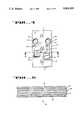
- FIG. 1illustrates a perspective view of a prior art actuator including individual transducers attached to actuator arm-assembly.
- FIG. 2is a top view of the prior art actuator of FIG. 1.
- FIG. 3is a perspective view of the head/flex connector of the currently preferred embodiment of the present invention.
- FIG. 4is a top view of the head-gimbal-assembly (“HGA”) connector used in conjunction with the currently preferred embodiment of the present invention.
- HGAhead-gimbal-assembly
- FIG. 5is a cross-sectional view of the HGA flex connector of FIG. 4.
- FIG. 6illustrates how the HGA flex connector is attached to the head/flex connector in order to make electrical contact to a first pair of terminals.
- FIG. 7illustrates how the HGA flex connector is attached to the head/flex connector in order to make electrical contact to a second pair of terminals.
- FIG. 8is a perspective view of the present invention after attachment to the actuator arm and following bar soldering of all connections.
- FIG. 9shows an alternative embodiment of the present invention.
- Actuator 10which is selectively rotatable about an axis 11.
- Actuator 10includes a coil 24 which resides within a magnet housing, (the housing is not shown in FIGS. 1 and 2 for clarity reasons).
- the combination of coil 24 and the magnetic housing of the disk driveprovide the means for rotating actuator 10 randomly across the magnetic medium thereby allowing rapid access of the heads to any desired track of the disk.
- Actuator 10also includes a plurality of arms 15 upon which are rigidly secured spring suspensions 16. At the end of each spring suspension 16 is a head element, or transducer 18. When the magnetic medium is rotated, a hydrodynamic bearing is generated at the disk-head interface. This provides a small and stable spacing between the heads and the disk during reading and writing of information.
- Each of the head elements 18include two or more wires 19 which provide the means for electrically transferring the binary signals from the read/write electronics of the system to the transducer and vice-a-versa.
- these wiresare conventionally run across spring suspension 16 and then across the upper portion of actuator arm 15. In most instances, they are glued or taped in place along arm 15.
- the individual wires 19are then manually soldered to a corresponding set of terminals 21.
- the terminals 21themselves are the electrical endpoints of a flexible connector cable 14. Cable 14 is conventionally mounted to the upper surface of actuator 10 and may optionally include various read/write circuitry 13. Most often, terminals 21 comprise solder-coated copper leads, while the other end of cable 14 is coupled to the read/write electronics of the magnetic recording system.
- connector 30is shown including a plurality of arm members 36 attached to end 31.
- Connector 30is also known as a head/flex connector (abbreviated "HFC").
- HFC 30is preferably formed of an injection-molded plastic having properties which make it both lightweight and durable.
- HFC 30comprises one portion of the present invention which obviates the hand-soldering operation characteristics of the prior art.
- Each of the plurality of arms 36 of HFC 30finds correspondence to the plurality of arms 15 of actuator 10 (see FIGS. 1 and 2).
- Each of the arms 36 of HFC 30includes a plurality of electrical traces 37.
- these traces 37comprise ordinary copper conductors which are formed on the upper and lower surfaces of arms 36 using the well-known plate and etch technology. This technology is commonly employed during the manufacture of printed circuit boards and is capable of producing inlaid electrical traces 37 in any geometric configuration--limited only by the particular printing process used.
- Individual traces 37terminate at end 31 of connector 30 in a plurality of bonding pads 39.
- Each of the plurality of bonding pads 39are coated with solder so as to be capable of making electrical connection upon contact with terminals 21 of cable 14.
- bonding pads 39are electrically coupled to corresponding locations on both the top and bottom surfaces of end 31 through a series of vias. In other words, every place where a bonding pad 39 appears on the top surface of HFC 30 in FIG. 3, there also exists a corresponding bonding pad 39 located on the bottom surface of end 31 which is electronically connected to its corresponding pad on the upper surface.
- FIG. 3shows electrical traces 37 running over the top surface of arms 36; however, additional traces 37 may also run along the bottom surface of arm 36 and terminated at bonding pads 39 along the underside of end 31.
- Bonding pads 39aare depicted as terminating traces 37 on the upper surface of end 31 while bonding pads 39b are depicted as terminating those traces 37 which extend along the underside of arms 36.
- bonding pads 39b and 39aare each electrically coupled to a corresponding set of bonding pads located along the opposite surface of end 31.
- traces 37are terminated near the other end 32 of arm 36 by a plurality of bonding pads 38.
- bonding pads 38are coated with solder and are capable of making electrical connection to other bonding pads placed in contact with them.
- bonding pads 38aterminate traces 37 on the top of arms 36 while bonding pads 38b terminate traces 37 running along the bottom of arm 36 as shown in FIG. 3 (note that the bottom traces 37 are not shown in FIG. 3 for obvious reasons). In this way, the number of traces 37 which may run along arm 36 is effectively doubled.
- bonding pads 38bare connected to the bottom of arm 36 through a corresponding plurality of vias. Bonding pads 38a, however, are not coupled to the underside of arm 36 in the currently preferred embodiment.
- each arm 36Also located near end 32 of each arm 36 are at least one or more alignment posts 33.
- a pair of alignment posts 33are formed adjacent to bonding pads 38.
- alignment posts 33enable an operator to align a small flex circuit (referred to as an HGA flex) to bonding pads 38 on the HFC 30.
- Alignment posts 33are normally integrally formed into the plastic substrate of arms 36, but in other embodiments they may be attached after the molding process used to form the connector 30 has been completed.
- FIG. 3further illustrates snap-fit clips 34 being integrally formed into the plastic substrate of HFC 30.
- a pair of clips 34are formed at the end 32 of connector 30.
- Each clipincludes a flanged end whose design is well-understood by practitioners in the art of plastic connectors.
- These clips 34facilitate attachment of HFC 30 onto the individual actuator arms 15.
- the connector 30is attached by placing the arms 36 over the corresponding arms 15 of the actuator, and then pressing connector 30 down until clips 34 first separate, and then firmly grasp actuator arms 15.
- An illustration of how connector 30 attaches onto actuator arms 15is provided in FIG. 8.
- each clip member 34comprises a flange which is distanced from the bottom surface of arm 36 by a distance equal to the dimension of the upper portion of arm 15. This insures a tight fit of HFC 30 to arms 15 which is important for stability purposes.
- traces 37are covered with an insulative layer everywhere except at the locations of bonding pads 39 and 38.
- HFC connector 30in the preferred embodiment, comprises an injection molded plastic material, it is appreciated that other materials may also be used without departing from the spirit or scope of the present invention.
- the chosen materialshould have a low specific gravity, since minimizing the total weight present on the actuator arms is important, and should be resilient enough to resist chipping, warping, twisting, etc.
- the materialshould not be prone to outgassing when placed in a vacuum environment since this would result in large levels of contaminates within the disk drive housing.
- the materialwhen integrated with clips 34, the material should not be so rigid as to prevent the flanges at the ends of clips 34 from separating to accept arms 15 during the attachment process.
- arms 36closely approximates the length of actuator arms 15 in the currently preferred embodiment. That is, ends 32 and bonding pads 38 are located near the end of arm 15 closest to head 18. Positioning bonding pads 38 at this point along arm 15 helps to minimize the length of wires 53 emanating from head element 18.
- arms 36may assume a length which is substantially less than the full extent of actuator arms 15.
- FIG. 4A top view of a flexible connector circuit is provided in FIG. 4 in which head gimbal assembly (HGA) flex connector 40 includes electrical traces 43 formed of copper conductors which are terminated at one end by bonding pads 44 and at the other end by bonding pads 45. Each of the traces 43 and bonding pads 44 and 45 are embedded within an insulative carrier material which comprises the outer surface of connector 40.
- HGAhead gimbal assembly
- FIG. 5shows a cross-sectional view of the flex connector 40 of FIG. 4 taken along cut lines A--A'.
- conductors 43are surrounded by an adhesive layer 51 which is then sandwiched in a polyimide casing 52.
- polyimide 52comprises a flexible insulator known as KaptonTM, which is manufactured by DuPont Corporation. (KaptonTM is a registered trademark of DuPont Corporation.) Both polyimide and adhesive layers 52 and 51, respectively, are approximately 0.001 inches thick in the preferred embodiment, while copper traces 43 are approximately 0.0007 inches thick.
- openings 47 and 48 in the polyimide 52 and adhesive 51 layersexpose bonding pads 45 and 44, respectively. Opening 48 is located only along the bottom surface of connector 40 while opening 47 is located only along the top surface. Bonding pads 44 and 45 are coated with solder, similar to the bonding pads 38 and 39 in FIG. 3.
- Openings 41are used in conjunction with alignment posts 33 to provide proper alignment of bonding pads 45 to bonding pads 38, as will be described in more detail later.
- alignment posts 33are used in conjunction with alignment posts 33 to provide proper alignment of bonding pads 45 to bonding pads 38, as will be described in more detail later.
- three holesare employed in the embodiment of FIG. 4.
- Other embodimentsmay use a different number of alignment posts or openings; or an entirely different alignment means altogether.
- FIG. 6shows transducer wires 53 bonded to pads 44 of HGA flex 40.
- Wires 53emanate from head 18 (not shown in FIG. 6) and are ordinarily soldered to connector 40 by the head vendor as a normal part of the manufacturing process.
- Two wires 53are shown in FIG. 6 being soldered to a corresponding pair of bonding pads 44.
- the number of wires 53 associated with a single headmay vary. By way of example, many transducers utilize three wires instead of two.
- HGA flex connector 40normally comprises a number of bonding pads 44, 45 and electrical traces 43 which corresponds to the number of head wires 53.
- the sameis true for the number of bonding pads 38, 39 and electrical traces 37 associated with HFC 30, with the exception that the number may be some multiple (where more than one head is associated with an arm 15).
- FIG. 6illustrates how bonding pads 45 are aligned with the corresponding bonding pads 38b of HFC 30.
- openings 41a and 41bare placed over alignment posts 33.
- the distance separating individual alignment posts 33must be equal to the distance separating individual openings 41a and 41b.
- the relative locations of alignment posts 33, openings 41a, 41b and bonding pads 45 and 38bare also arranged such that placement of HGA flex 40 over alignment posts 33 results in alignment of bonding pads 45 with corresponding bonding pads 38b, thereby providing electrical connection between the respective bonding pads.
- bonding pads 38ado not make electrical contact with any of the bonding pads of HGA flex 40 for the situation illustrated in FIG. 6.
- HGA flex connector 40ahas previously been attached to HFC connector 30 wherein alignment posts 33 pass through openings 41a and 41b. Head wires 53a are shown coupled to the electrical traces of HGA flex connector 40a. Since in most instances, a pair of head elements are associated with a single actuator arm 15, the present invention accommodates an additional head element as follows: The second head is coupled to HGA flex connector 40b through wires 53b which are solder-bonded to bonding pads 44b. Openings 41b and 41c are then passed through alignment posts 33 to align bonding pads 45 of connector 40b with bonding pads 38a of connector 30. Because the individual connectors 40 are relatively thin and flexible, the fact that connector 40a underlies connector 40b does not affect the connection between bonding pads 45 and 38a.
- bonding pads 45are aligned with and make electrical contact to, bonding pads 38a without shorting, or otherwise making electrical connection to, any other electrical traces.
- bonding pads 45 and 44 for the respective connectors 40a and 40bare aligned in FIG. 7 so that the electrical traces and the bonding pads associated with each connector 40a and 40b remain insulated from each other.
- Such an arrangementallows two heads to be electrically coupled along a single arm 36 of HFC 30.
- the connector apparatus of the currently preferred embodiment of the present inventionis shown attached to actuator arms 15 by means of clips 44.
- Head wires 53are solder-bonded to individual HGA flex connectors 40 which are then connected to the top surface of arms 36 by means of alignment posts 33 and openings 41.
- HGA flex connector 40is shown attached to each of the arms 36 for clarity reasons. Normally, two such connectors 40 would be mounted in accordance with the teachings of FIGS. 6 and 7).
- Connector 30is attached so that bonding pads 39 are aligned with and make electrical contact to the terminals 21 formed along the end of flex cable 14.
- bonding pads 39are aligned with and make electrical contact to the terminals 21 formed along the end of flex cable 14.
- bar-solderingpermanent electrical connections from bonding pads 39 to terminals 21 and from bonding pads 45 to bonding pads 38 are formed. In the bar-soldering technology, this is ordinarily achieved by placing a heated metal bar across the length of end 31 and then across each of the HGA flex connectors 40. The end result, of course, is that each of the transducers are now electrically coupled to the read/write electronics of the magnetic recording system.
- the conductive path for individual headsis as follows: Head wires 53 emanating from individual heads 18 are first soldered to bonding pads 44 of HGA flex connector 40. These bonding pads are then electrically coupled via traces 43 to a corresponding plurality of bonding pads 45 at the other end of connector 40. Connector 40, itself, is next manually placed over a plurality of alignments posts so that bonding pads 45 are thereby aligned with and provide electrical connection to corresponding pads 38 located along the top surface of arms 36 of connector 30. Bonding pads 38, in turn, are coupled via electrical traces 37 down the length of each of arm 36 to a corresponding plurality of bonding pads 39 disposed along end 31 of connector 30. When connector 30 is attached along actuator arm 15, bonding pads 39 are in alignment with, and provide electrical contact to terminals 21 of read/write connector cable 14. This completes the electrical path.
- FIG. 9An alternative embodiment is shown in FIG. 9 wherein connector 30 is eliminated.
- the length of head wires 53is extended across the entire length of actuator arm 15.
- wires 53are guided by groove 58 formed in the upper surface of arm 15.
- theymay be taped or glued.
- wires 53terminate at HGA flex connector 40 in a similar manner as that described above in connection with FIGS. 3-8. That is, individual wires 53 are solder bonded to bonding pads 44 at one end of connector 40.
- Mounted onto the end of cable 14are alignment posts 59, which have the function as posts 33 described above.
- openings 41 and connector 40are placed through posts 59 so as to align bonding pads 45 to terminals 21 at the end of cable 14. It is appreciated that the identical scheme of using three openings 41 and two posts 59 to allow alignment to two different sets of terminals 21 easily employed in the embodiment of FIG. 9. Other alignment means are also possible and are considered to be within skill of an ordinary practitioner in the art.
- FIG. 9has the advantage of having fewer elements which reduces the overall cost and ease of manufacturing by a considerable margin. Moreover, eliminating connector 30 further reduces the total mass associated with actuator arm 15. As is appreciated by practitioners in the art, a lower arm mass facilitates rapid rotation of actuator 10, thereby making faster access times possible. Ordinarily, the plastic arms 36 of connector 30 are about twice the weight of wires 53 (for a given length of actuator arm 15).
Landscapes
- Adjustment Of The Magnetic Head Position Track Following On Tapes (AREA)
Abstract
Description
Claims (7)
Priority Applications (1)
| Application Number | Priority Date | Filing Date | Title |
|---|---|---|---|
| US07/475,363US5103359A (en) | 1990-02-05 | 1990-02-05 | Connector apparatus for electrically coupling a transducer to the electronics of a magnetic recording system |
Applications Claiming Priority (1)
| Application Number | Priority Date | Filing Date | Title |
|---|---|---|---|
| US07/475,363US5103359A (en) | 1990-02-05 | 1990-02-05 | Connector apparatus for electrically coupling a transducer to the electronics of a magnetic recording system |
Publications (1)
| Publication Number | Publication Date |
|---|---|
| US5103359Atrue US5103359A (en) | 1992-04-07 |
Family
ID=23887248
Family Applications (1)
| Application Number | Title | Priority Date | Filing Date |
|---|---|---|---|
| US07/475,363Expired - Fee RelatedUS5103359A (en) | 1990-02-05 | 1990-02-05 | Connector apparatus for electrically coupling a transducer to the electronics of a magnetic recording system |
Country Status (1)
| Country | Link |
|---|---|
| US (1) | US5103359A (en) |
Cited By (65)
| Publication number | Priority date | Publication date | Assignee | Title |
|---|---|---|---|---|
| US5305168A (en)* | 1992-03-05 | 1994-04-19 | Magnex Corporation | Thin film transducer suspension assembly with flexuro mounted booster element |
| WO1995013609A1 (en)* | 1993-11-12 | 1995-05-18 | Conner Peripherals, Inc. | Wire carrier for disk drive |
| US5419033A (en)* | 1990-10-02 | 1995-05-30 | International Business Machines Corporation | Method of making load spring manufacturing assembly having an electric conductor carrying and positioning tail for carrying a conductor bonded to the surface of a load spring |
| US5491597A (en)* | 1994-04-15 | 1996-02-13 | Hutchinson Technology Incorporated | Gimbal flexure and electrical interconnect assembly |
| US5495377A (en)* | 1993-05-27 | 1996-02-27 | Seagate Technology, Inc. | Apparatus for attaching a printed circuit cable to an actuator arm in a disc drive assembly utilizing alignment pins |
| DE19528270A1 (en)* | 1994-10-04 | 1996-04-11 | Fujitsu Ltd | Magnetic disc drive with electrical connection system |
| US5539595A (en)* | 1993-03-02 | 1996-07-23 | International Business Machines Corporation | Structure and enclosure assembly for a disk drive |
| US5541788A (en)* | 1992-07-20 | 1996-07-30 | Fujitsu Limited | Magnetic disk drive and flexible printed circuit board |
| DE19541336A1 (en)* | 1995-03-17 | 1996-09-19 | Fujitsu Ltd | Magnetic disc drive read=write head signal feed and pick=off structure |
| US5570250A (en)* | 1991-12-04 | 1996-10-29 | Western Digital Corporation | Disk drive head disk assembly actuator mount mechanism |
| US5583720A (en)* | 1994-02-10 | 1996-12-10 | Fujitsu Limited | Magnetic disk drive and flexible printed board used in such drive |
| US5583721A (en)* | 1994-04-23 | 1996-12-10 | Samsung Electronics Co., Ltd. | Connecting device of a flexible printed circuit in a hard disk drive |
| US5598307A (en)* | 1994-04-15 | 1997-01-28 | Hutchinson Technology Inc. | Integrated gimbal suspension assembly |
| US5608591A (en)* | 1995-06-09 | 1997-03-04 | International Business Machines Corporation | Integrated head-electronics interconnection suspension for a data recording disk drive |
| US5631786A (en)* | 1994-05-19 | 1997-05-20 | International Business Machines Corporation | Termination pad manipulator for a laminated suspension in a data storage system |
| US5644452A (en)* | 1994-04-18 | 1997-07-01 | Seagate Technology, Inc. | Apparatus connecting a flexible circuit to an actuator arm of a disc drive |
| US5661896A (en)* | 1995-05-19 | 1997-09-02 | International Business Machines Corporation | Method of manufacturing a termination pad manipulator for a laminated suspension in a data storage system |
| US5668684A (en)* | 1996-08-06 | 1997-09-16 | International Business Machines Corporation | Electrical interconnect for a head/arm assembly of computer disk drives |
| US5717541A (en)* | 1992-09-28 | 1998-02-10 | Fujitsu Limited | Flexible circuit assembly for disk storage system |
| US5781380A (en)* | 1997-04-01 | 1998-07-14 | Western Digital Corporation | Swing-type actuator assembly having internal conductors |
| US5808836A (en)* | 1995-08-30 | 1998-09-15 | International Business Machines Corporation | Load beam with grooved wire-gluing region |
| US5808834A (en)* | 1995-06-07 | 1998-09-15 | Hutchinson Technology Incorporated | Laminated adapter |
| US5810094A (en)* | 1996-05-09 | 1998-09-22 | W. L. Gore & Associates, Inc. | Head/pre-amp ribbon interconnect for data storage devices |
| US5818667A (en)* | 1995-03-31 | 1998-10-06 | Western Digital Corporation | Retaining apparatus for a disk drive actuator assembly electrical flex circuit |
| US5835306A (en)* | 1995-06-07 | 1998-11-10 | Hutchinson Technology Incorporated | Integrated gimbal suspension assembly with assymetric bond pad |
| US5839193A (en)* | 1994-04-15 | 1998-11-24 | Hutchinson Technology Incorporated | Method of making laminated structures for a disk drive suspension assembly |
| US5844753A (en)* | 1995-04-13 | 1998-12-01 | Nippon Mektron Ltd. | Magnetic head junction board and manufacturing method for the same |
| US5847902A (en)* | 1994-10-12 | 1998-12-08 | Hewlett-Packard Company | Head suspension assembly having parallel-coupled load/gimbal springs |
| US5870253A (en)* | 1993-12-07 | 1999-02-09 | Fujitsu Limited | Flat cable connecting system for rotary type actuators in magnetic disk drives |
| US5876216A (en)* | 1997-03-25 | 1999-03-02 | Seagate Technology, Inc. | Integrated connector board for disc drive storage systems |
| US5883759A (en)* | 1996-02-22 | 1999-03-16 | Seagate Technology, Inc. | Flex circuit head interconnect for improved electrical performance and ease of assembly |
| US5901016A (en)* | 1997-07-21 | 1999-05-04 | Magnecomp Corp. | Disk drive suspension with hybrid leads |
| KR19990053020A (en)* | 1997-12-23 | 1999-07-15 | 윤종용 | Signal board on hard disk drive |
| US5953183A (en)* | 1997-11-17 | 1999-09-14 | Western Digital Corporation | Head stack assembly for a magnetic disk drive with a pass-through flex circuit cable |
| US5982584A (en)* | 1996-12-19 | 1999-11-09 | Hutchinson Technology Incorporated | Integrated lead suspension flexure with serially arranged metal-backed and suspended insulator portions for hygrothermal compensation |
| US6031693A (en)* | 1992-04-20 | 2000-02-29 | Sony Corporation | Sliding-type magnetic head for magnetooptical recording |
| US6069318A (en)* | 1998-03-20 | 2000-05-30 | Fujitsu Limited | Formed wire for actuator |
| US6098271A (en)* | 1994-10-04 | 2000-08-08 | Fujitsu Limited | Method for assembling a magnetic disk drive with a relaying flexible printed circuit sheet |
| US6134075A (en)* | 1994-04-15 | 2000-10-17 | Hutchinson Technology Incorporated | Magnetic head suspension with single layer preshaped trace interconnect |
| US6147839A (en)* | 1996-12-23 | 2000-11-14 | Hutchinson Technology, Inc. | Head suspension with outriggers extending across a spring region |
| US6313970B1 (en)* | 1994-02-18 | 2001-11-06 | Maxtor Corporation | Disk drive with low profile suspension assemblies |
| US6381100B1 (en) | 1996-12-19 | 2002-04-30 | Hutchinson Technology Incorporated | Integrated lead suspension flexure with balanced parallel leads for insulator layer hygrothermal compensation |
| US6399889B1 (en)* | 1998-09-14 | 2002-06-04 | Seagate Technology Llc | Head interconnect circuit with alignment finger |
| US6477014B1 (en)* | 1994-05-19 | 2002-11-05 | International Business Machines Corporation | Multilayered suspension with conductive lead structure extending beyond base layer |
| US20030043508A1 (en)* | 2001-09-05 | 2003-03-06 | Schulz Kevin Jon | Flex on suspension with actuator dynamic function |
| US20030086206A1 (en)* | 2001-11-05 | 2003-05-08 | Kube Todd Warren | Load beam attachment to actuator arm |
| US6612016B1 (en) | 1997-12-18 | 2003-09-02 | Hutchinson Technology Incorporated | Method of making integrated lead suspension flexure with balanced parallel leads for insulator layer hygrothermal compensation |
| US6650506B1 (en) | 1999-12-15 | 2003-11-18 | Patrick Risse | Double-sided disk storage using a single configuration of magnetoresistive head |
| US6765763B2 (en)* | 2000-06-16 | 2004-07-20 | Seagate Technology Llc | Actuator system for disc drive |
| US20040240118A1 (en)* | 2003-05-29 | 2004-12-02 | Hitachi Global Storage Technologies Netherlands, B.V. | Wire support member and rotary disk storage device |
| KR100501693B1 (en)* | 1998-02-18 | 2005-09-30 | 삼성전자주식회사 | Actuator on hard disk drive |
| US20050254176A1 (en)* | 2004-05-12 | 2005-11-17 | Mcreynolds Dave P | Disc drive integral actuator pins |
| US20050268456A1 (en)* | 2004-06-07 | 2005-12-08 | Kabushiki Kaisha Toshiba | Method of manufacturing head actuator assembly and method of manufacturing disk device |
| US20060034018A1 (en)* | 2004-08-09 | 2006-02-16 | Hitachi Global Storage Technologies Netherlands B.V. | Magnetic disk drive, wiring connection structure and terminal structure |
| DE4447813B4 (en)* | 1993-12-07 | 2006-05-24 | Fujitsu Ltd., Kawasaki | Magnetic hard disc appts. - has head arm system pivot-mounted with distance from head to pivot greater than distance from arm pivot to disc spindle centre |
| US7059868B1 (en) | 2000-03-07 | 2006-06-13 | Western Digital (Fremont), Inc. | Connection of trace circuitry in a computer disk drive system |
| US20090086374A1 (en)* | 2007-10-01 | 2009-04-02 | Seagate Technology Llc | High density electrical interconnect assembly |
| US7522382B1 (en)* | 2005-08-22 | 2009-04-21 | Western Digital (Fremont), Llc | Head stack assembly with interleaved flexure tail bond pad rows |
| US7729091B1 (en) | 2005-12-06 | 2010-06-01 | Western Digital Technologies, Inc. | Clip for mounting a flex cable within a head stack assembly |
| US9036306B1 (en)* | 2013-12-19 | 2015-05-19 | HGST Netherlands B.V. | Grounding for a hard disk drive suspension tail |
| US9214174B1 (en) | 2010-10-29 | 2015-12-15 | Western Digital Technologies, Inc. | Method of manufacturing a disk drive head gimbal assembly having a flexure tail with folded bond pads |
| US9324344B1 (en) | 2013-12-10 | 2016-04-26 | Western Digital Technologies, Inc. | Disk drive head suspension tail with ground pad outside of bonding region |
| US9330695B1 (en) | 2013-12-10 | 2016-05-03 | Western Digital Technologies, Inc. | Disk drive head suspension tail with a noble metal layer disposed on a plurality of structural backing islands |
| US9633680B2 (en) | 2010-10-29 | 2017-04-25 | Western Digital Technologies, Inc. | Head suspension having a flexure tail with a covered conductive layer and structural layer bond pads |
| US20200090688A1 (en)* | 2018-09-19 | 2020-03-19 | Kabushiki Kaisha Toshiba | Wiring board unit for disk devices, actuator assembly for disk devices and disk device comprising the same |
Citations (14)
| Publication number | Priority date | Publication date | Assignee | Title |
|---|---|---|---|---|
| US4293883A (en)* | 1979-12-26 | 1981-10-06 | International Business Machines Corporation | Magnetic head mount assembly |
| US4295700A (en)* | 1978-10-12 | 1981-10-20 | Shin-Etsu Polymer Co., Ltd. | Interconnectors |
| US4432027A (en)* | 1980-07-11 | 1984-02-14 | Canon Kabushiki Kaisha | Magnetic head |
| US4538865A (en)* | 1983-02-08 | 1985-09-03 | Nippon Kogaku K.K. | Device for connecting printed wiring boards or sheets |
| US4642716A (en)* | 1982-10-28 | 1987-02-10 | Sony Corporation | Magnetic transducer head assembly with support system therefor |
| US4645280A (en)* | 1985-08-08 | 1987-02-24 | Rogers Corporation | Solderless connection technique between data/servo flex circuits and magnetic disc heads |
| US4670804A (en)* | 1985-10-15 | 1987-06-02 | International Business Machines Corporation | Expandable suspension for a read/write head in a disk file |
| US4741101A (en)* | 1986-09-29 | 1988-05-03 | Tektronix, Inc. | Contact device |
| US4759119A (en)* | 1985-09-10 | 1988-07-26 | Alps Electric Co., Ltd. | Method of fabricating a magnetic head assembly |
| US4761699A (en)* | 1986-10-28 | 1988-08-02 | International Business Machines Corporation | Slider-suspension assembly and method for attaching a slider to a suspension in a data recording disk file |
| US4788613A (en)* | 1986-01-30 | 1988-11-29 | Alps Electric Co., Ltd. | Magnetic head having coil bobbin for mounting printed circuit board |
| US4792875A (en)* | 1986-10-03 | 1988-12-20 | Alps Electric Co., Ltd. | Gimbal spring for floating type magnetic head |
| US4799129A (en)* | 1986-04-07 | 1989-01-17 | Tanashin Denki Co., Ltd. | Flat cable connecting device |
| US4823217A (en)* | 1984-07-05 | 1989-04-18 | Canon Denshi Kabushiki Kaisha | Circuiting device |
- 1990
- 1990-02-05USUS07/475,363patent/US5103359A/ennot_activeExpired - Fee Related
Patent Citations (14)
| Publication number | Priority date | Publication date | Assignee | Title |
|---|---|---|---|---|
| US4295700A (en)* | 1978-10-12 | 1981-10-20 | Shin-Etsu Polymer Co., Ltd. | Interconnectors |
| US4293883A (en)* | 1979-12-26 | 1981-10-06 | International Business Machines Corporation | Magnetic head mount assembly |
| US4432027A (en)* | 1980-07-11 | 1984-02-14 | Canon Kabushiki Kaisha | Magnetic head |
| US4642716A (en)* | 1982-10-28 | 1987-02-10 | Sony Corporation | Magnetic transducer head assembly with support system therefor |
| US4538865A (en)* | 1983-02-08 | 1985-09-03 | Nippon Kogaku K.K. | Device for connecting printed wiring boards or sheets |
| US4823217A (en)* | 1984-07-05 | 1989-04-18 | Canon Denshi Kabushiki Kaisha | Circuiting device |
| US4645280A (en)* | 1985-08-08 | 1987-02-24 | Rogers Corporation | Solderless connection technique between data/servo flex circuits and magnetic disc heads |
| US4759119A (en)* | 1985-09-10 | 1988-07-26 | Alps Electric Co., Ltd. | Method of fabricating a magnetic head assembly |
| US4670804A (en)* | 1985-10-15 | 1987-06-02 | International Business Machines Corporation | Expandable suspension for a read/write head in a disk file |
| US4788613A (en)* | 1986-01-30 | 1988-11-29 | Alps Electric Co., Ltd. | Magnetic head having coil bobbin for mounting printed circuit board |
| US4799129A (en)* | 1986-04-07 | 1989-01-17 | Tanashin Denki Co., Ltd. | Flat cable connecting device |
| US4741101A (en)* | 1986-09-29 | 1988-05-03 | Tektronix, Inc. | Contact device |
| US4792875A (en)* | 1986-10-03 | 1988-12-20 | Alps Electric Co., Ltd. | Gimbal spring for floating type magnetic head |
| US4761699A (en)* | 1986-10-28 | 1988-08-02 | International Business Machines Corporation | Slider-suspension assembly and method for attaching a slider to a suspension in a data recording disk file |
Cited By (97)
| Publication number | Priority date | Publication date | Assignee | Title |
|---|---|---|---|---|
| US5419033A (en)* | 1990-10-02 | 1995-05-30 | International Business Machines Corporation | Method of making load spring manufacturing assembly having an electric conductor carrying and positioning tail for carrying a conductor bonded to the surface of a load spring |
| US5570250A (en)* | 1991-12-04 | 1996-10-29 | Western Digital Corporation | Disk drive head disk assembly actuator mount mechanism |
| US5305168A (en)* | 1992-03-05 | 1994-04-19 | Magnex Corporation | Thin film transducer suspension assembly with flexuro mounted booster element |
| EP0667606A1 (en)* | 1992-03-05 | 1995-08-16 | Magnex Corporation | Thin film transducer and separated transformer |
| AU671697B2 (en)* | 1992-03-05 | 1996-09-05 | Magnex Corporation | Thin film transducer and separated transformer |
| US6031693A (en)* | 1992-04-20 | 2000-02-29 | Sony Corporation | Sliding-type magnetic head for magnetooptical recording |
| US5541788A (en)* | 1992-07-20 | 1996-07-30 | Fujitsu Limited | Magnetic disk drive and flexible printed circuit board |
| US5717541A (en)* | 1992-09-28 | 1998-02-10 | Fujitsu Limited | Flexible circuit assembly for disk storage system |
| US5539595A (en)* | 1993-03-02 | 1996-07-23 | International Business Machines Corporation | Structure and enclosure assembly for a disk drive |
| US5495377A (en)* | 1993-05-27 | 1996-02-27 | Seagate Technology, Inc. | Apparatus for attaching a printed circuit cable to an actuator arm in a disc drive assembly utilizing alignment pins |
| WO1995013609A1 (en)* | 1993-11-12 | 1995-05-18 | Conner Peripherals, Inc. | Wire carrier for disk drive |
| US5805377A (en)* | 1993-11-12 | 1998-09-08 | Seagate Technology, Inc. | Wire carrier for disk drive |
| DE4447813B4 (en)* | 1993-12-07 | 2006-05-24 | Fujitsu Ltd., Kawasaki | Magnetic hard disc appts. - has head arm system pivot-mounted with distance from head to pivot greater than distance from arm pivot to disc spindle centre |
| US5870253A (en)* | 1993-12-07 | 1999-02-09 | Fujitsu Limited | Flat cable connecting system for rotary type actuators in magnetic disk drives |
| US6243236B1 (en) | 1993-12-07 | 2001-06-05 | Fujitsu Limited | Magnetic disk apparatus |
| US5910862A (en)* | 1993-12-07 | 1999-06-08 | Fujitsu Limited | Magnetic disk apparatus |
| US5859746A (en)* | 1994-02-10 | 1999-01-12 | Fujitsu Limited | Magnetic disk drive and flexible printed board used in such drive |
| US5583720A (en)* | 1994-02-10 | 1996-12-10 | Fujitsu Limited | Magnetic disk drive and flexible printed board used in such drive |
| US6493187B2 (en) | 1994-02-18 | 2002-12-10 | Maxtor Corporation | Disk drive with low profile head suspension assemblies |
| US6313970B1 (en)* | 1994-02-18 | 2001-11-06 | Maxtor Corporation | Disk drive with low profile suspension assemblies |
| US5491597A (en)* | 1994-04-15 | 1996-02-13 | Hutchinson Technology Incorporated | Gimbal flexure and electrical interconnect assembly |
| US5839193A (en)* | 1994-04-15 | 1998-11-24 | Hutchinson Technology Incorporated | Method of making laminated structures for a disk drive suspension assembly |
| US5645735A (en)* | 1994-04-15 | 1997-07-08 | Hutchinson Technology Incorporated | Gimbal flexure and electrical interconnect assembly |
| US6134075A (en)* | 1994-04-15 | 2000-10-17 | Hutchinson Technology Incorporated | Magnetic head suspension with single layer preshaped trace interconnect |
| US6587310B1 (en) | 1994-04-15 | 2003-07-01 | Hutchinson Technology, Inc. | Magnetic head suspension with single layer preshaped trace interconnect |
| US5864445A (en)* | 1994-04-15 | 1999-01-26 | Hutchinson Technology Incorporated | Hygrothermal load compensating structures in an integrated lead suspension |
| US5598307A (en)* | 1994-04-15 | 1997-01-28 | Hutchinson Technology Inc. | Integrated gimbal suspension assembly |
| US5644452A (en)* | 1994-04-18 | 1997-07-01 | Seagate Technology, Inc. | Apparatus connecting a flexible circuit to an actuator arm of a disc drive |
| US5583721A (en)* | 1994-04-23 | 1996-12-10 | Samsung Electronics Co., Ltd. | Connecting device of a flexible printed circuit in a hard disk drive |
| US5708541A (en)* | 1994-05-19 | 1998-01-13 | International Business Machines Corporation | Termination pad manipulator for a laminated suspension in a data storage system |
| US5631786A (en)* | 1994-05-19 | 1997-05-20 | International Business Machines Corporation | Termination pad manipulator for a laminated suspension in a data storage system |
| US6477014B1 (en)* | 1994-05-19 | 2002-11-05 | International Business Machines Corporation | Multilayered suspension with conductive lead structure extending beyond base layer |
| US6098271A (en)* | 1994-10-04 | 2000-08-08 | Fujitsu Limited | Method for assembling a magnetic disk drive with a relaying flexible printed circuit sheet |
| DE19528270A1 (en)* | 1994-10-04 | 1996-04-11 | Fujitsu Ltd | Magnetic disc drive with electrical connection system |
| US6201667B1 (en)* | 1994-10-04 | 2001-03-13 | Fujitsu Limited | Magnetic disk drive having a relaying flexible printed circuit sheet |
| DE19528270C2 (en)* | 1994-10-04 | 2001-08-02 | Fujitsu Ltd | Magnetic disk drive |
| US5847902A (en)* | 1994-10-12 | 1998-12-08 | Hewlett-Packard Company | Head suspension assembly having parallel-coupled load/gimbal springs |
| US5644448A (en)* | 1995-03-17 | 1997-07-01 | Fujitsu Limited | Head signal supply/retrieval structure for magnetic disk drive |
| DE19541336C2 (en)* | 1995-03-17 | 2001-08-02 | Fujitsu Ltd | Head signal delivery / recovery assembly for a magnetic disk drive |
| USRE37869E1 (en) | 1995-03-17 | 2002-10-08 | Fujitsu Limited | Head signal supply/retrieval structure for magnetic disc drive |
| DE19541336A1 (en)* | 1995-03-17 | 1996-09-19 | Fujitsu Ltd | Magnetic disc drive read=write head signal feed and pick=off structure |
| US5818667A (en)* | 1995-03-31 | 1998-10-06 | Western Digital Corporation | Retaining apparatus for a disk drive actuator assembly electrical flex circuit |
| US5844753A (en)* | 1995-04-13 | 1998-12-01 | Nippon Mektron Ltd. | Magnetic head junction board and manufacturing method for the same |
| US5661896A (en)* | 1995-05-19 | 1997-09-02 | International Business Machines Corporation | Method of manufacturing a termination pad manipulator for a laminated suspension in a data storage system |
| US5835306A (en)* | 1995-06-07 | 1998-11-10 | Hutchinson Technology Incorporated | Integrated gimbal suspension assembly with assymetric bond pad |
| US5808834A (en)* | 1995-06-07 | 1998-09-15 | Hutchinson Technology Incorporated | Laminated adapter |
| US5608591A (en)* | 1995-06-09 | 1997-03-04 | International Business Machines Corporation | Integrated head-electronics interconnection suspension for a data recording disk drive |
| US6112400A (en)* | 1995-08-30 | 2000-09-05 | International Business Machines Corporation | Apparatus and method for adhesively connecting wires to a suspension arm in a disk drive assembly |
| US5808836A (en)* | 1995-08-30 | 1998-09-15 | International Business Machines Corporation | Load beam with grooved wire-gluing region |
| US5883759A (en)* | 1996-02-22 | 1999-03-16 | Seagate Technology, Inc. | Flex circuit head interconnect for improved electrical performance and ease of assembly |
| US5810094A (en)* | 1996-05-09 | 1998-09-22 | W. L. Gore & Associates, Inc. | Head/pre-amp ribbon interconnect for data storage devices |
| US5668684A (en)* | 1996-08-06 | 1997-09-16 | International Business Machines Corporation | Electrical interconnect for a head/arm assembly of computer disk drives |
| US5982584A (en)* | 1996-12-19 | 1999-11-09 | Hutchinson Technology Incorporated | Integrated lead suspension flexure with serially arranged metal-backed and suspended insulator portions for hygrothermal compensation |
| US6381100B1 (en) | 1996-12-19 | 2002-04-30 | Hutchinson Technology Incorporated | Integrated lead suspension flexure with balanced parallel leads for insulator layer hygrothermal compensation |
| US6147839A (en)* | 1996-12-23 | 2000-11-14 | Hutchinson Technology, Inc. | Head suspension with outriggers extending across a spring region |
| US6150813A (en)* | 1997-03-25 | 2000-11-21 | Seagate Technology Llc | Method of connecting heads of a data storage system to a testing apparatus |
| US5876216A (en)* | 1997-03-25 | 1999-03-02 | Seagate Technology, Inc. | Integrated connector board for disc drive storage systems |
| US5781380A (en)* | 1997-04-01 | 1998-07-14 | Western Digital Corporation | Swing-type actuator assembly having internal conductors |
| US6205003B1 (en)* | 1997-07-21 | 2001-03-20 | Magnecomp Corp. | Disk drive suspension with hybrid leads |
| US5901016A (en)* | 1997-07-21 | 1999-05-04 | Magnecomp Corp. | Disk drive suspension with hybrid leads |
| US5953183A (en)* | 1997-11-17 | 1999-09-14 | Western Digital Corporation | Head stack assembly for a magnetic disk drive with a pass-through flex circuit cable |
| US6612016B1 (en) | 1997-12-18 | 2003-09-02 | Hutchinson Technology Incorporated | Method of making integrated lead suspension flexure with balanced parallel leads for insulator layer hygrothermal compensation |
| KR19990053020A (en)* | 1997-12-23 | 1999-07-15 | 윤종용 | Signal board on hard disk drive |
| KR100501693B1 (en)* | 1998-02-18 | 2005-09-30 | 삼성전자주식회사 | Actuator on hard disk drive |
| US6069318A (en)* | 1998-03-20 | 2000-05-30 | Fujitsu Limited | Formed wire for actuator |
| US6399889B1 (en)* | 1998-09-14 | 2002-06-04 | Seagate Technology Llc | Head interconnect circuit with alignment finger |
| US6634086B2 (en) | 1998-09-14 | 2003-10-21 | Seagate Technology Llc | Method for connecting a head interconnect circuit with alignment finger to a printed circuit |
| US6650506B1 (en) | 1999-12-15 | 2003-11-18 | Patrick Risse | Double-sided disk storage using a single configuration of magnetoresistive head |
| US7059868B1 (en) | 2000-03-07 | 2006-06-13 | Western Digital (Fremont), Inc. | Connection of trace circuitry in a computer disk drive system |
| US6765763B2 (en)* | 2000-06-16 | 2004-07-20 | Seagate Technology Llc | Actuator system for disc drive |
| US20030043508A1 (en)* | 2001-09-05 | 2003-03-06 | Schulz Kevin Jon | Flex on suspension with actuator dynamic function |
| US6865058B2 (en)* | 2001-11-05 | 2005-03-08 | Seagate Technology Llc | Load beam attachment to actuator arm |
| US20030086206A1 (en)* | 2001-11-05 | 2003-05-08 | Kube Todd Warren | Load beam attachment to actuator arm |
| US20040240118A1 (en)* | 2003-05-29 | 2004-12-02 | Hitachi Global Storage Technologies Netherlands, B.V. | Wire support member and rotary disk storage device |
| CN100423122C (en)* | 2003-05-29 | 2008-10-01 | 日立环球储存科技荷兰有限公司 | Wire support components and carousel storage |
| US7154712B2 (en)* | 2003-05-29 | 2006-12-26 | Hitachi Global Storage Technologies Netherlands B.V. | Wire support member and rotary disk storage device |
| US20050254176A1 (en)* | 2004-05-12 | 2005-11-17 | Mcreynolds Dave P | Disc drive integral actuator pins |
| US7355818B2 (en) | 2004-05-12 | 2008-04-08 | Seagate Technology Llc | Disc drive integral actuator pins |
| US7424774B2 (en)* | 2004-06-07 | 2008-09-16 | Kabushiki Kaisha Toshiba | Method of manufacturing a head actuator assembly and a disk drive |
| US20050268456A1 (en)* | 2004-06-07 | 2005-12-08 | Kabushiki Kaisha Toshiba | Method of manufacturing head actuator assembly and method of manufacturing disk device |
| US20080307636A1 (en)* | 2004-06-07 | 2008-12-18 | Kabushiki Kaisha Toshiba | Method of manufacturing head actuator assembly and method of manufacturing disk device |
| US7372669B2 (en)* | 2004-08-09 | 2008-05-13 | Hitachi Global Storage Technologies Netherlands B.V. | Magnetic disk drive, wiring connection structure and terminal structure |
| US20060034018A1 (en)* | 2004-08-09 | 2006-02-16 | Hitachi Global Storage Technologies Netherlands B.V. | Magnetic disk drive, wiring connection structure and terminal structure |
| US7522382B1 (en)* | 2005-08-22 | 2009-04-21 | Western Digital (Fremont), Llc | Head stack assembly with interleaved flexure tail bond pad rows |
| US7961436B1 (en) | 2005-12-06 | 2011-06-14 | Western Digital Technologies, Inc. | Disk drive head stack assembly with clip for mounting a flex cable |
| US7729091B1 (en) | 2005-12-06 | 2010-06-01 | Western Digital Technologies, Inc. | Clip for mounting a flex cable within a head stack assembly |
| US7952833B2 (en)* | 2007-10-01 | 2011-05-31 | Seagate Technology Llc | High density electrical interconnect assembly |
| US20090086374A1 (en)* | 2007-10-01 | 2009-04-02 | Seagate Technology Llc | High density electrical interconnect assembly |
| US9214174B1 (en) | 2010-10-29 | 2015-12-15 | Western Digital Technologies, Inc. | Method of manufacturing a disk drive head gimbal assembly having a flexure tail with folded bond pads |
| US9633680B2 (en) | 2010-10-29 | 2017-04-25 | Western Digital Technologies, Inc. | Head suspension having a flexure tail with a covered conductive layer and structural layer bond pads |
| US9953667B2 (en) | 2010-10-29 | 2018-04-24 | Western Digital Technologies, Inc. | Disk drive system |
| US9324344B1 (en) | 2013-12-10 | 2016-04-26 | Western Digital Technologies, Inc. | Disk drive head suspension tail with ground pad outside of bonding region |
| US9330695B1 (en) | 2013-12-10 | 2016-05-03 | Western Digital Technologies, Inc. | Disk drive head suspension tail with a noble metal layer disposed on a plurality of structural backing islands |
| US9881640B2 (en) | 2013-12-10 | 2018-01-30 | Western Digital Technologies, Inc. | Disk drive head suspension tail with a noble metal layer disposed on a plurality of structural backing islands |
| US9036306B1 (en)* | 2013-12-19 | 2015-05-19 | HGST Netherlands B.V. | Grounding for a hard disk drive suspension tail |
| US20200090688A1 (en)* | 2018-09-19 | 2020-03-19 | Kabushiki Kaisha Toshiba | Wiring board unit for disk devices, actuator assembly for disk devices and disk device comprising the same |
| US11410691B2 (en) | 2018-09-19 | 2022-08-09 | Kabushiki Kaisha Toshiba | Wiring board unit for disk devices, actuator assembly for disk devices and disk device comprising the same |
Similar Documents
| Publication | Publication Date | Title |
|---|---|---|
| US5103359A (en) | Connector apparatus for electrically coupling a transducer to the electronics of a magnetic recording system | |
| US5121273A (en) | Computer disk head interconnect assembly | |
| US7522382B1 (en) | Head stack assembly with interleaved flexure tail bond pad rows | |
| US6704165B2 (en) | Attachment of a head-gimbal assembly to a printed circuit board actuator arm using Z-axis conductive adhesive film | |
| US6650506B1 (en) | Double-sided disk storage using a single configuration of magnetoresistive head | |
| KR100366675B1 (en) | Low inductance flex-to-pcb spring connector for disc drive | |
| USRE37869E1 (en) | Head signal supply/retrieval structure for magnetic disc drive | |
| US8018688B2 (en) | Head stack assembly with spacers to partition drive arms | |
| US5668684A (en) | Electrical interconnect for a head/arm assembly of computer disk drives | |
| US7064928B2 (en) | Method and apparatus for providing an additional ground pad and electrical connection for grounding a magnetic recording head | |
| US6702592B1 (en) | Printed circuit board assembly with secondary side rigid electrical pin to mate with compliant contact | |
| US5991123A (en) | HDD head stack assembly having conductive traces supported by the sides of the actuator arm to extend in planar arrays | |
| US6721135B2 (en) | Printed circuit cable connector attachment assembly | |
| US6665149B2 (en) | Connector for flexible printed circuit boards, head actuator provided with the same, and disk drive | |
| US7113372B2 (en) | HGA plateau gimbal design | |
| US7110222B2 (en) | System and apparatus for assembling hard disk drive integrated lead suspensions to arm electronics cables via additional degrees of freedom at the tail termination and impedance grooming thereof | |
| US20220076697A1 (en) | Disk device | |
| US6018439A (en) | Connector assembly for connecting transducing heads to a flex circuit of a disc drive | |
| US5831788A (en) | Circuit connector | |
| JP3413051B2 (en) | Magnetic disk drive | |
| US6057982A (en) | Disc drive head disc assembly and printed circuit board connected with flexible connectors | |
| US6781795B2 (en) | Connector for flexible printed circuit boards, head actuator provided with the same, and disk drive | |
| US5343344A (en) | Connection of transducer leads to a printed circuit board in rotating disk data storage apparatus | |
| US20010049210A1 (en) | 3.5 inch form factor compatible connector for 2.5 inch form factor disc drive | |
| JP2021136044A (en) | Disk equipment and its manufacturing method |
Legal Events
| Date | Code | Title | Description |
|---|---|---|---|
| AS | Assignment | Owner name:MAXTOR CORPORATION, A CORP. OF DE, CALIFORNIA Free format text:ASSIGNMENT OF ASSIGNORS INTEREST.;ASSIGNOR:MARAZZO, PENNY J.;REEL/FRAME:005227/0588 Effective date:19900201 | |
| AS | Assignment | Owner name:BARCLAYS BANK PLC, AS AGENT Free format text:SECURITY INTEREST;ASSIGNOR:MAXTOR CORPORATION;REEL/FRAME:006627/0866 Effective date:19930727 | |
| AS | Assignment | Owner name:CIT GROUP/BUSINESS CREDIT, INC., CALIFORNIA Free format text:ASSIGNMENT OF ASSIGNORS INTEREST;ASSIGNOR:MAXTOR CORPORATION;REEL/FRAME:006714/0408 Effective date:19930916 Owner name:MAXTOR CORP., CALIFORNIA Free format text:ASSIGNMENT OF ASSIGNORS INTEREST;ASSIGNOR:BARCLAYS BANK PLC;REEL/FRAME:006826/0171 Effective date:19930917 | |
| FEPP | Fee payment procedure | Free format text:PAYOR NUMBER ASSIGNED (ORIGINAL EVENT CODE: ASPN); ENTITY STATUS OF PATENT OWNER: LARGE ENTITY | |
| REMI | Maintenance fee reminder mailed | ||
| LAPS | Lapse for failure to pay maintenance fees | ||
| FP | Lapsed due to failure to pay maintenance fee | Effective date:19960410 | |
| STCH | Information on status: patent discontinuation | Free format text:PATENT EXPIRED DUE TO NONPAYMENT OF MAINTENANCE FEES UNDER 37 CFR 1.362 |