US5103211A - Apparatus for detecting fluid line occlusion - Google Patents
Apparatus for detecting fluid line occlusionDownload PDFInfo
- Publication number
- US5103211A US5103211AUS07/610,385US61038590AUS5103211AUS 5103211 AUS5103211 AUS 5103211AUS 61038590 AUS61038590 AUS 61038590AUS 5103211 AUS5103211 AUS 5103211A
- Authority
- US
- United States
- Prior art keywords
- sensor
- finger
- pressure
- upstream
- downstream
- Prior art date
- Legal status (The legal status is an assumption and is not a legal conclusion. Google has not performed a legal analysis and makes no representation as to the accuracy of the status listed.)
- Expired - Lifetime
Links
Images


Classifications
- A—HUMAN NECESSITIES
- A61—MEDICAL OR VETERINARY SCIENCE; HYGIENE
- A61M—DEVICES FOR INTRODUCING MEDIA INTO, OR ONTO, THE BODY; DEVICES FOR TRANSDUCING BODY MEDIA OR FOR TAKING MEDIA FROM THE BODY; DEVICES FOR PRODUCING OR ENDING SLEEP OR STUPOR
- A61M5/00—Devices for bringing media into the body in a subcutaneous, intra-vascular or intramuscular way; Accessories therefor, e.g. filling or cleaning devices, arm-rests
- A61M5/14—Infusion devices, e.g. infusing by gravity; Blood infusion; Accessories therefor
- A61M5/168—Means for controlling media flow to the body or for metering media to the body, e.g. drip meters, counters ; Monitoring media flow to the body
- A61M5/16831—Monitoring, detecting, signalling or eliminating infusion flow anomalies
- A61M5/16854—Monitoring, detecting, signalling or eliminating infusion flow anomalies by monitoring line pressure
- A61M5/16859—Evaluation of pressure response, e.g. to an applied pulse
- Y—GENERAL TAGGING OF NEW TECHNOLOGICAL DEVELOPMENTS; GENERAL TAGGING OF CROSS-SECTIONAL TECHNOLOGIES SPANNING OVER SEVERAL SECTIONS OF THE IPC; TECHNICAL SUBJECTS COVERED BY FORMER USPC CROSS-REFERENCE ART COLLECTIONS [XRACs] AND DIGESTS
- Y10—TECHNICAL SUBJECTS COVERED BY FORMER USPC
- Y10S—TECHNICAL SUBJECTS COVERED BY FORMER USPC CROSS-REFERENCE ART COLLECTIONS [XRACs] AND DIGESTS
- Y10S128/00—Surgery
- Y10S128/13—Infusion monitoring
Definitions
- This inventionrelates generally to a device for detecting occlusion in a fluid line, and more particularly relates to detection of occlusion in a fluid line upstream or downstream of a peristaltic type pump used for infusion of intravenous solutions to a patient.
- peristaltic type of pumphas been found to be advantageous in allowing the pumping of intravenous fluid through conventional, flexible fluid lines without fluid contact. It has been found that the operation of peristaltic pumps also allows for a wide variety of control and sensing of patency and fluid flow conditions. Important data concerning flow status can be gathered by monitoring fluid pressure changes within the intravenous fluid line.
- a pressure sensing strain gauge assemblyin a peristaltic pump in order to monitor dimensional changes in the outer diameter of an intravenous tube as an indication of fluid pressure changes in the tube in known from U.S. Pat. No. 4,690,673.
- the strain gaugeis attached to a strain beam which is part of an assembly mounted on a fixed mounting block to press with a generally constant displacement of the fluid line.
- a pressure sensorwhich presses against the line with a certain degree of displacement of the fluid line only during a limited portion of the duty cycle of the pump.
- Such a moving pressure sensorcan avoid interfering with the fluid flow during the portion of the duty cycle when the pressure sensor is not pressing against the fluid line, and would allow for periodic calibration of the pressure sensor as well.
- Coordination of the movement of the pressure sensor with cam follower fingers of a peristaltic pumpwould be desirable in order to avoid interfering with the operation of the pump, while enhancing the accuracy of pressure measurements obtained.
- the present inventionaddresses these needs.
- the present inventionprovides an improved system for detecting pressure and occlusion in a fluid line being operated upon by a positive displacement, peristaltic pump having several cam follower fingers pressing against the fluid line sequentially to force fluid through the line peristaltically.
- a sensor follower fingeris mounted to the cam shaft of the pump among the other peristaltic fingers in order to cyclicly press against the fluid line and displace it by a certain amount as the cam shaft rotates.
- the sensor follower fingersincludes a strain gauge mounted on the sensor finger to generate a signal indicating the degree of force being applied by the sensor finger against the tubing, and a signal processor unit which receives this force signal determines the pressure within the fluid line based upon the signal.
- the signal processorcompares the measured pressure to an upstream reference value and provides an occlusion alarm if the result of the comparison indicates a pressure below that reference value.
- the signal processorsubtracts the measured upstream pressure from the measured downstream pressure and compares this difference pressure to a downstream reference value. In the event that the comparison indicates the difference pressure to exceed the reference value, an occlusion alarm may be provided.
- the force sensoris preferably a strain gauge mounted on a portion of the sensor finger which is subject to strain forces as the sensor finger presses against the tubing.
- an apparatus for measuring pressure within a flexible tubing being operated upon by a peristaltic pump having a plurality of cam follower fingersincludes a sensor finger periodically pressing against the tubing wall with a predetermined displacement of the tubing wall without occluding the fluid line, a sensor for measuring the force exerted by the sensor finger on the tubing wall and generating a force signal indicative of the force; a signal processing unit for determining the measured pressure based upon the force signal, and for comparing the measured pressure with upstream and downstream pressure reference values during upstream and downstream modes, respectively as described above.
- the pressure measurement apparatusincludes an alarm for indicating an occlusion condition, based upon the comparison.
- the force sensoralso preferably comprises a strain gauge mounted on a portion of the sensor finger for measuring the force exerted by the sensor finger on the tubing wall, and the strain gauge is most preferably placed within an aperture in the portion of the sensor finger which engages the tubing wall.
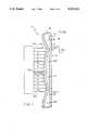
- FIG. 1is a simplified sectional view of the peristaltic finger mechanism operating upon a fluid line, and showing the placement of the sensor of the invention
- FIG. 2is a side elevational view of a sensor follower according to the invention journalled to a cam shaft drive;
- FIG. 3is a view similar to FIG. 1 showing the sensor follower in position during an upstream mode of the peristaltic pump;
- FIG. 4is a schematic diagram of the relationship of the sensor follower to flexible tubing within the peristaltic pump.
- FIG. 5is a flow chart illustrating the operation of the signal processing unit.
- the inventionis embodied in an apparatus and method for measuring pressure in a fluid line received in a peristaltic pump, and for determining whether the fluid line is occluded upstream or downstream of the pump mechanism.
- the apparatuscomprises a sensor follower finger journalled to a rotating cam shaft and centrally located among a plurality of cam follower fingers journalled to the cam shaft.
- the sensor follower fingeris adapted to press against the flexible tubing wall at a generally central portion of the segment of fluid line received in the peristaltic pump, intermediate the upstream end and downstream end cam followers.
- the sensor followeris adapted to cyclically press against the segment of tubing for a portion of the pump duty cycle with predetermined displacement of the tubing wall without occluding the fluid line.
- a sensor associated with the sensor follower fingermeasures the force exerted by the sensor follower finger on the tubing segment, and a signal processing unit receives the upstream and downstream pressures and determines whether occlusion has occurred upstream or downstream from the pump.
- an apparatus for measuring pressure within a compressible pumping segment of a fluid line having a flexible tubing wallincluding a peristaltic pump mechanism for receiving the pumping segment, the peristaltic pump mechanism having a rotating camshaft and a plurality of cam follower fingers journalled thereto and including an upstream end cam follower finger and a downstream end cam follower finger adapted to sequentially press against the pumping segment producing cyclically recurring upstream and downstream pressure communication modes of a duty cycle of the pump in which a central portion of the pumping segment is alternately in communication with only an upstream portion of the fluid line and only a downstream portion of the fluid line, respectively, the apparatus comprising a sensor follower finger journalled to the camshaft adjacent the central portion of the pumping segment and intermediate the upstream end cam follower and the downstream end cam follower, and adapted to cyclically press against the pumping segment for a portion of the duty cycle with a predetermine displacement of the tubing wall without occluding the
- the inventionalso provides a method for measuring pressure within a pumping segment of a fluid line having a flexible tubing wall, comprising the steps of periodically compressing the pumping segment with at least one finger member with a predetermined amount of displacement of the flexible tubing wall without occluding the fluid line; measuring a force parameter exerted by the finger member on the flexible tubing wall; generating a force signal indicating the measured force parameter; and determining fluid pressure within the tubing responsive to the force signal.
- a peristaltic pump mechanism 10is adapted to receive a flexible fluid tubing 12, to force fluid through the tubing in the direction of the arrow 14.
- the fluid tubingincludes a compressible pumping segment 16 from approximately the location A to the location B, between the inlet end 18 of the tubing and the outlet end 20.
- the tubingis typically continuous, and flexible throughout its length, it is also possible that an inflexible tubing could be used, with an intermediate compressible pumping segment spliced into the inflexible tubing at the inlet and outlet ends of the compressible pumping segment, to allow a peristaltic pump mechansim to act upon the pumping segment.
- the peristaltic pump mechanismalso includes a portion of the pump housing 22 adjacent one side of the flexible tubing, and typically several peristaltic cam follower fingers 23 journalled to a camshaft 24, which drives the peristaltic cam follower fingers to sequentially press against the flexible tubing wall of the pumping segment to force the fluid in the tubing to flow by peristaltic movement.
- the camrotates about its off center axis of rotation 26, the cam surface 28 precesses around the axis, causing the cam follower fingers to sequentially press against and move away from the tubing wall.
- the uppermost finger 30is shown as occluding fluid tubing at the location 34, and finger No. 2, finger No. 3, finger No. 4, and so on sequentially press against the tubing and occlude the fluid flow at the area of contact, forcing fluid along the tubing.
- the downstream portion of the fluid tubingwill be sealed off from communication with the central portion of the fluid tubing, where the non-occluding sensor follower finger 36 is approximately located.
- fluid pressure from the upstream portion of the tubingis in fluid communication through the fluid tubing portion 35 with the tubing area adjacent the sensor follower finger.
- the downstream fingers culminating in finger 32release, opening the central area adjacent the sensor follower to fluid communication with the downstream portion of the tubing 20 through the area 37 just downstream of the sensor follower.
- an upstream mode of communication with the central area of the tubingcan be defined with relation to the point of occlusion, so that when the peristaltic point of occlusion is downstream from the sensor follower and the fluid line is opened to communication upstream of the sensor follower, the peristaltic pump mechanism is in an upstream mode of pressure communication, and when the point of occlusion is upstream of the sensor follower and the downstream portion of the tubing is open to communicate pressure to the sensor follower finger, the apparatus is in a downstream mode of pressure communication.
- the sensor follower finger 36is generally of the same shape and construction as that of the other can follower fingers.
- the sensor follower fingerincludes cam follower arms 38a, 38b adapted to cooperate within and follow the rotation of the cam drive, and having an interior U-shaped cam follower section 40, in the main body portion 42.
- the sensor follower fingerincludes a pivot aperture 44, so that the finger can be mounted to pivot in response to the cam drive, to move the tube pressing arm 46 to press against and move away from the flexible tubing.
- the tube pressing armpreferably includes a protective aperture 48 containing a strain gauge mounted therein to monitor the force applied by the tube pressing arm against the flexible tubing.
- the strain gaugeis electrically connected by the wire 52 to a signal processing unit 53, typically a microprocessor based unit or computer, which receives the force signal output from the strain gauge, and which in turn generates an occlusion error signal which may drive an alarm 54, as will be explained hereinafter.
- a signal processing unit 53typically a microprocessor based unit or computer, which receives the force signal output from the strain gauge, and which in turn generates an occlusion error signal which may drive an alarm 54, as will be explained hereinafter.
- the sensor follower fingeris driven with a cam that is different from the cam sections of the other cam follower fingers, so that the sensor follower finger will not occlude the tubing, but will contact the tubing wall in order to press against the wall with a limited displacement of the tubing wall.
- the cam for this sensor follower fingeris preferably formed so that if the follower No. 2 is occluding the tubing, the sensor follower will be in contact with and pressing against the tubing, so that if the tubing is occluded downstream the sensor will reflect the occlusion in the output force signal.
- the sensor followerwill again be in contact with the tubing so that if, for example, an upstream roller clamp is closed, a negative pressure will occur, which will result in a vacuum within the compressible segment of the tubing, the tubing will collapse, and the sensor follower will indicate an upstream occlusion.
- FIG. 4A non-occluding sensor follower arm or blade 36 is sown as being directed against the fluid line 12 with a degree of force (in grams) and in a direction indicated by the vector 62.
- the blade displacement 64 of the tubing wallis in opposition to the applied pressure 66 within the fluid.
- the signal processing unitideally receives input from a rotational phase indicator 70, which may take the form of an optical flag assembly which interrupts a photoelectric beam, either in conjunction with the cam drive itself or a motor (not shown) which drives the rotation of the cam shaft.
- a rotational phase indicator 70which may take the form of an optical flag assembly which interrupts a photoelectric beam, either in conjunction with the cam drive itself or a motor (not shown) which drives the rotation of the cam shaft.
- the signal processorcan identify which of the cam follower fingers is occluding the fluid line at any given moment during the duty cycle of the pump. A determination is made at 72 whether the most upstream cam follower finger is occluding the fluid line. If it is not, the same decision is made at 74 concerning the most downstream cam follower finger, finger No. 12. If finger No.
- a typical minimum pressure thresholdwould be zero, so that if the pressure level were determined to be above this level, at 84, there would not be the indicated upstream occlusion, and if a pressure less than zero were detected, this would give an indication at 86 of an upstream occlusion error condition, which may also result in an alarm signal to the alarm 88.
- finger No. 1is occluding the fluid line, it can be determined at 90 whether a measured pressure difference between the downstream and upstream measured pressures is above a maximum threshold. If the measured pressure difference is less than the maximum pressure threshold, such as for example 10 psig, then the determination at 92 would be that no downstream occlusion exists. Otherwise, if the measured pressure difference were above this maximum threshold, the signal processing unit would generate a downstream occlusion error signal, and the signal processing unit may also generate an alarm signal to activate the alarm 88.
- a pressure difference between measured downstream and upstream pressuresis used to determine if an occlusion exists
- the measured downstream pressurealone may be compared to a threshold to determine the existence or nonexistence of a downstream occlusion.
- the system of the invention for measuring pressure within the fluid linecan be used for detecting occlusion within the fluid line either upstream or downstream from a peristaltic pump mechanism operating on the fluid line. It is also significant that the sensor follower finger is adapted for movement correlated with that of the other cam follower fingers in order to avoid restriction of fluid flow, and to allow periodic calibration of the sensor.
Landscapes
- Health & Medical Sciences (AREA)
- Vascular Medicine (AREA)
- Engineering & Computer Science (AREA)
- Anesthesiology (AREA)
- Biomedical Technology (AREA)
- Heart & Thoracic Surgery (AREA)
- Hematology (AREA)
- Life Sciences & Earth Sciences (AREA)
- Animal Behavior & Ethology (AREA)
- General Health & Medical Sciences (AREA)
- Public Health (AREA)
- Veterinary Medicine (AREA)
- Infusion, Injection, And Reservoir Apparatuses (AREA)
- Reciprocating Pumps (AREA)
Abstract
Description
Claims (32)
Priority Applications (1)
| Application Number | Priority Date | Filing Date | Title |
|---|---|---|---|
| US07/610,385US5103211A (en) | 1989-11-02 | 1990-11-06 | Apparatus for detecting fluid line occlusion |
Applications Claiming Priority (2)
| Application Number | Priority Date | Filing Date | Title |
|---|---|---|---|
| US43080989A | 1989-11-02 | 1989-11-02 | |
| US07/610,385US5103211A (en) | 1989-11-02 | 1990-11-06 | Apparatus for detecting fluid line occlusion |
Related Parent Applications (1)
| Application Number | Title | Priority Date | Filing Date |
|---|---|---|---|
| US43080989AContinuation-In-Part | 1989-11-02 | 1989-11-02 |
Publications (1)
| Publication Number | Publication Date |
|---|---|
| US5103211Atrue US5103211A (en) | 1992-04-07 |
Family
ID=27028775
Family Applications (1)
| Application Number | Title | Priority Date | Filing Date |
|---|---|---|---|
| US07/610,385Expired - LifetimeUS5103211A (en) | 1989-11-02 | 1990-11-06 | Apparatus for detecting fluid line occlusion |
Country Status (1)
| Country | Link |
|---|---|
| US (1) | US5103211A (en) |
Cited By (116)
| Publication number | Priority date | Publication date | Assignee | Title |
|---|---|---|---|---|
| US5292306A (en)* | 1993-01-29 | 1994-03-08 | Abbott Laboratories | Method of detecting occlusions in a solution pumping system |
| US5356378A (en)* | 1992-01-22 | 1994-10-18 | Ivac Corporation | Fluid line condition detection |
| US5382232A (en)* | 1992-03-13 | 1995-01-17 | Ivac Corporation | Infusion system with air-in-line clear function |
| US5431627A (en)* | 1993-11-12 | 1995-07-11 | Abbott Laboratories | Cassette identification system for use with a multi-program drug infusion pump |
| US5531698A (en)* | 1994-04-15 | 1996-07-02 | Sims Deltec, Inc. | Optical reflection systems and methods for cassette identification fordrug pumps |
| US5554115A (en)* | 1995-04-07 | 1996-09-10 | Abbott Laboratories | Sensor for measuring pressures in a cassette pump proximal and distal to a pumping chamber |
| US5609576A (en)* | 1994-09-13 | 1997-03-11 | Ivac Medical Systems, Inc. | Fluid flow impedance monitoring system |
| US5657000A (en)* | 1995-06-02 | 1997-08-12 | Cobe Laboratories, Inc. | Peristaltic pump occlusion detector and adjuster |
| US5695473A (en)* | 1994-07-27 | 1997-12-09 | Sims Deltec, Inc. | Occlusion detection system for an infusion pump |
| WO1998004303A1 (en)* | 1996-07-30 | 1998-02-05 | Alaris Medical Systems, Inc. | Fluid flow resistance monitoring system |
| US5791881A (en)* | 1996-10-18 | 1998-08-11 | Moubayed; Ahmad-Maher | Curvilinear peristaltic pump with occlusion detection means |
| US5807322A (en)* | 1994-03-21 | 1998-09-15 | Graseby Medical Limited | Pumping and pressure detection using flexible tubes |
| US5827223A (en)* | 1995-08-31 | 1998-10-27 | Alaris Medical Systems, Inc. | Upstream occulsion detection system |
| US5853386A (en) | 1996-07-25 | 1998-12-29 | Alaris Medical Systems, Inc. | Infusion device with disposable elements |
| US5935099A (en) | 1992-09-09 | 1999-08-10 | Sims Deltec, Inc. | Drug pump systems and methods |
| US6070761A (en) | 1997-08-22 | 2000-06-06 | Deka Products Limited Partnership | Vial loading method and apparatus for intelligent admixture and delivery of intravenous drugs |
| US6077055A (en)* | 1998-12-03 | 2000-06-20 | Sims Deltec, Inc. | Pump system including cassette sensor and occlusion sensor |
| FR2790041A1 (en)* | 1999-02-23 | 2000-08-25 | Fresenius Vial | METHOD FOR MONITORING A PUMPING DEVICE COMPRISING A PUMP PROVIDED WITH A FLEXIBLE TUBE AND DEVICE FOR CARRYING OUT THE METHOD |
| US6149394A (en)* | 1999-02-26 | 2000-11-21 | Allen; Alton K. | Occlusion detection means for a persistaltic pump |
| US6158965A (en)* | 1996-07-30 | 2000-12-12 | Alaris Medical Systems, Inc. | Fluid flow resistance monitoring system |
| US6213972B1 (en) | 1994-09-13 | 2001-04-10 | Alaris Medical Systems, Inc. | Fluid flow resistance monitoring system |
| US6283719B1 (en)* | 1998-11-05 | 2001-09-04 | Frantz Medical Development Ltd | Detecting obstructions in enteral/parenteral feeding tubes and automatic removal of clogs therefrom |
| US6423029B1 (en)* | 1999-04-29 | 2002-07-23 | Medtronic, Inc. | System and method for detecting abnormal medicament pump fluid pressure |
| US20020183693A1 (en)* | 1992-09-09 | 2002-12-05 | Sims Deltec, Inc. | Drug pump systems and methods |
| US6616633B1 (en) | 1997-09-19 | 2003-09-09 | Alaris Medical Systems, Inc. | Apparatus and method for air-in-line detection |
| US20060002799A1 (en)* | 2004-06-30 | 2006-01-05 | Millipore Corporation | Peristaltic pump comprising a bearing member and a counter-member adapted to cooperate with a tube |
| US20060130592A1 (en)* | 2004-12-22 | 2006-06-22 | Chadwell Thomas J | Method and apparatus for a product displacement sensing device |
| US20070078381A1 (en)* | 2002-08-12 | 2007-04-05 | Marc Yap | System and method for blockage detection for medication infusion |
| US20070078380A1 (en)* | 2002-08-12 | 2007-04-05 | Marc Yap | System and method for tension-activated fluid control |
| US20070269324A1 (en)* | 2004-11-24 | 2007-11-22 | O-Core Ltd. | Finger-Type Peristaltic Pump |
| US20090221964A1 (en)* | 2004-11-24 | 2009-09-03 | Q-Core Medical Ltd | Peristaltic infusion pump with locking mechanism |
| US20090240201A1 (en)* | 2006-11-13 | 2009-09-24 | Q-Core Medical Ltd | Magnetically balanced finger-type peristaltic pump |
| US20090317268A1 (en)* | 2006-11-13 | 2009-12-24 | Q-Core Medical Ltd | Finger-type peristaltic pump comprising a ribbed anvil |
| US20100036322A1 (en)* | 2006-11-13 | 2010-02-11 | Q-Core Medical Ltd. | Anti-free flow mechanism |
| US20100214110A1 (en)* | 2009-02-20 | 2010-08-26 | Hospira, Inc. | Occlusion detection system |
| US20110060284A1 (en)* | 2009-09-10 | 2011-03-10 | Tyco Healthcare Group Lp | Compact peristaltic medical pump |
| US20110152772A1 (en)* | 2009-12-22 | 2011-06-23 | Q-Core Medical Ltd | Peristaltic Pump with Bi-Directional Pressure Sensor |
| US20110152831A1 (en)* | 2009-12-22 | 2011-06-23 | Q-Core Medical Ltd | Peristaltic Pump with Linear Flow Control |
| US20110318198A1 (en)* | 2010-06-23 | 2011-12-29 | Hospira, Inc. | Fluid Flow Rate Compensation System Using an Integrated Conductivity Sensor to Monitor Tubing Changes |
| US8133197B2 (en) | 2008-05-02 | 2012-03-13 | Smiths Medical Asd, Inc. | Display for pump |
| US8149131B2 (en) | 2006-08-03 | 2012-04-03 | Smiths Medical Asd, Inc. | Interface for medical infusion pump |
| WO2012021656A3 (en)* | 2010-08-11 | 2012-04-26 | Zevex, Inc. | Pressure sensor and method of use |
| US8250483B2 (en) | 2002-02-28 | 2012-08-21 | Smiths Medical Asd, Inc. | Programmable medical infusion pump displaying a banner |
| US8287495B2 (en) | 2009-07-30 | 2012-10-16 | Tandem Diabetes Care, Inc. | Infusion pump system with disposable cartridge having pressure venting and pressure feedback |
| US8408421B2 (en) | 2008-09-16 | 2013-04-02 | Tandem Diabetes Care, Inc. | Flow regulating stopcocks and related methods |
| US8435206B2 (en) | 2006-08-03 | 2013-05-07 | Smiths Medical Asd, Inc. | Interface for medical infusion pump |
| US8504179B2 (en) | 2002-02-28 | 2013-08-06 | Smiths Medical Asd, Inc. | Programmable medical infusion pump |
| WO2013134448A1 (en)* | 2012-03-09 | 2013-09-12 | Zevex, Inc | Occlusion detection method |
| US8650937B2 (en) | 2008-09-19 | 2014-02-18 | Tandem Diabetes Care, Inc. | Solute concentration measurement device and related methods |
| WO2014072195A1 (en) | 2012-11-09 | 2014-05-15 | Fresenius Vial Sas | Method for operating a peristaltic pump |
| US8763445B2 (en) | 2011-12-07 | 2014-07-01 | International Business Machines Corporation | Detecting leaks in a fluid cooling system by sensing for a drop of fluid pressure in the system |
| US8858526B2 (en) | 2006-08-03 | 2014-10-14 | Smiths Medical Asd, Inc. | Interface for medical infusion pump |
| US8954336B2 (en) | 2004-02-23 | 2015-02-10 | Smiths Medical Asd, Inc. | Server for medical device |
| US8965707B2 (en) | 2006-08-03 | 2015-02-24 | Smiths Medical Asd, Inc. | Interface for medical infusion pump |
| US8986253B2 (en) | 2008-01-25 | 2015-03-24 | Tandem Diabetes Care, Inc. | Two chamber pumps and related methods |
| US9173998B2 (en) | 2013-03-14 | 2015-11-03 | Tandem Diabetes Care, Inc. | System and method for detecting occlusions in an infusion pump |
| US20150374903A1 (en)* | 2014-06-30 | 2015-12-31 | Minebea Co., Ltd. | Occlusion detection device, transfusion apparatus, and occlusion detection method |
| US9421329B2 (en) | 2013-03-15 | 2016-08-23 | Tandem Diabetes Care, Inc. | Infusion device occlusion detection system |
| US9457158B2 (en) | 2010-04-12 | 2016-10-04 | Q-Core Medical Ltd. | Air trap for intravenous pump |
| US9674811B2 (en) | 2011-01-16 | 2017-06-06 | Q-Core Medical Ltd. | Methods, apparatus and systems for medical device communication, control and localization |
| EP3052608A4 (en)* | 2013-10-03 | 2017-06-07 | Parker Hannifin Corporation | Dielectric elastomer valve assembly |
| US9675756B2 (en) | 2011-12-21 | 2017-06-13 | Deka Products Limited Partnership | Apparatus for infusing fluid |
| US9677555B2 (en) | 2011-12-21 | 2017-06-13 | Deka Products Limited Partnership | System, method, and apparatus for infusing fluid |
| US9726167B2 (en) | 2011-06-27 | 2017-08-08 | Q-Core Medical Ltd. | Methods, circuits, devices, apparatuses, encasements and systems for identifying if a medical infusion system is decalibrated |
| US9761790B2 (en) | 2012-06-18 | 2017-09-12 | Parker-Hannifin Corporation | Stretch frame for stretching process |
| US9786834B2 (en) | 2012-04-12 | 2017-10-10 | Parker-Hannifin Corporation | EAP transducers with improved performance |
| US9855110B2 (en) | 2013-02-05 | 2018-01-02 | Q-Core Medical Ltd. | Methods, apparatus and systems for operating a medical device including an accelerometer |
| US9876160B2 (en) | 2012-03-21 | 2018-01-23 | Parker-Hannifin Corporation | Roll-to-roll manufacturing processes for producing self-healing electroactive polymer devices |
| US9954159B2 (en) | 2012-08-16 | 2018-04-24 | Parker-Hannifin Corporation | Electrical interconnect terminals for rolled dielectric elastomer transducers |
| US10022498B2 (en) | 2011-12-16 | 2018-07-17 | Icu Medical, Inc. | System for monitoring and delivering medication to a patient and method of using the same to minimize the risks associated with automated therapy |
| WO2018154317A1 (en)* | 2017-02-24 | 2018-08-30 | Quanta Dialysis Technologies Ltd | Testing rotor engagement of a rotary peristaltic pump |
| US10166328B2 (en) | 2013-05-29 | 2019-01-01 | Icu Medical, Inc. | Infusion system which utilizes one or more sensors and additional information to make an air determination regarding the infusion system |
| US10258736B2 (en) | 2012-05-17 | 2019-04-16 | Tandem Diabetes Care, Inc. | Systems including vial adapter for fluid transfer |
| US10265463B2 (en) | 2014-09-18 | 2019-04-23 | Deka Products Limited Partnership | Apparatus and method for infusing fluid through a tube by appropriately heating the tube |
| US10347374B2 (en) | 2008-10-13 | 2019-07-09 | Baxter Corporation Englewood | Medication preparation system |
| US10342917B2 (en) | 2014-02-28 | 2019-07-09 | Icu Medical, Inc. | Infusion system and method which utilizes dual wavelength optical air-in-line detection |
| US10430761B2 (en) | 2011-08-19 | 2019-10-01 | Icu Medical, Inc. | Systems and methods for a graphical interface including a graphical representation of medical data |
| US10463788B2 (en) | 2012-07-31 | 2019-11-05 | Icu Medical, Inc. | Patient care system for critical medications |
| US10578474B2 (en) | 2012-03-30 | 2020-03-03 | Icu Medical, Inc. | Air detection system and method for detecting air in a pump of an infusion system |
| US10596316B2 (en) | 2013-05-29 | 2020-03-24 | Icu Medical, Inc. | Infusion system and method of use which prevents over-saturation of an analog-to-digital converter |
| US10635784B2 (en) | 2007-12-18 | 2020-04-28 | Icu Medical, Inc. | User interface improvements for medical devices |
| US10646405B2 (en) | 2012-10-26 | 2020-05-12 | Baxter Corporation Englewood | Work station for medical dose preparation system |
| US10656894B2 (en) | 2017-12-27 | 2020-05-19 | Icu Medical, Inc. | Synchronized display of screen content on networked devices |
| US10682460B2 (en) | 2013-01-28 | 2020-06-16 | Smiths Medical Asd, Inc. | Medication safety devices and methods |
| US10818387B2 (en) | 2014-12-05 | 2020-10-27 | Baxter Corporation Englewood | Dose preparation data analytics |
| US10850024B2 (en) | 2015-03-02 | 2020-12-01 | Icu Medical, Inc. | Infusion system, device, and method having advanced infusion features |
| US20200397987A1 (en)* | 2017-10-24 | 2020-12-24 | Carefusion 303, Inc. | Occlusion detection for infusion pumps |
| US10874793B2 (en) | 2013-05-24 | 2020-12-29 | Icu Medical, Inc. | Multi-sensor infusion system for detecting air or an occlusion in the infusion system |
| USD907211S1 (en) | 2017-09-28 | 2021-01-05 | Quanta Dialysis Technologies Ltd. | Dialysis machine |
| US10971257B2 (en) | 2012-10-26 | 2021-04-06 | Baxter Corporation Englewood | Image acquisition for medical dose preparation system |
| US11107574B2 (en) | 2014-09-30 | 2021-08-31 | Baxter Corporation Englewood | Management of medication preparation with formulary management |
| US11135360B1 (en) | 2020-12-07 | 2021-10-05 | Icu Medical, Inc. | Concurrent infusion with common line auto flush |
| US11246985B2 (en) | 2016-05-13 | 2022-02-15 | Icu Medical, Inc. | Infusion pump system and method with common line auto flush |
| US11278671B2 (en) | 2019-12-04 | 2022-03-22 | Icu Medical, Inc. | Infusion pump with safety sequence keypad |
| US11295846B2 (en) | 2011-12-21 | 2022-04-05 | Deka Products Limited Partnership | System, method, and apparatus for infusing fluid |
| US11324888B2 (en) | 2016-06-10 | 2022-05-10 | Icu Medical, Inc. | Acoustic flow sensor for continuous medication flow measurements and feedback control of infusion |
| US11344673B2 (en) | 2014-05-29 | 2022-05-31 | Icu Medical, Inc. | Infusion system and pump with configurable closed loop delivery rate catch-up |
| US11344668B2 (en) | 2014-12-19 | 2022-05-31 | Icu Medical, Inc. | Infusion system with concurrent TPN/insulin infusion |
| US11571499B2 (en) | 2015-12-30 | 2023-02-07 | Quanta Dialysis Technologies Ltd. | Dialysis machine |
| US11583618B2 (en) | 2014-06-02 | 2023-02-21 | Quanta Dialysis Technologies Limited | Method of heat sanitization of a haemodialysis water circuit using a calculated dose |
| US11660382B2 (en) | 2016-12-23 | 2023-05-30 | Quanta Dialysis Technologies Limited | Valve leak detection system |
| US11679189B2 (en) | 2019-11-18 | 2023-06-20 | Eitan Medical Ltd. | Fast test for medical pump |
| US11707615B2 (en) | 2018-08-16 | 2023-07-25 | Deka Products Limited Partnership | Medical pump |
| US11883361B2 (en) | 2020-07-21 | 2024-01-30 | Icu Medical, Inc. | Fluid transfer devices and methods of use |
| USRE49881E1 (en) | 2013-03-28 | 2024-03-26 | Quanta Fluid Solutions Ltd. | Re-use of a hemodialysis cartridge |
| US11948112B2 (en) | 2015-03-03 | 2024-04-02 | Baxter Corporation Engelwood | Pharmacy workflow management with integrated alerts |
| US11951284B2 (en) | 2020-08-27 | 2024-04-09 | Tandem Diabetes Care, Inc. | Transitioning to other modes in automated insulin delivery |
| USRE50004E1 (en) | 2013-08-14 | 2024-06-11 | Quanta Dialysis Technologies Ltd. | Dual haemodialysis and haemodiafiltration blood treatment device |
| US12011528B2 (en) | 2017-02-02 | 2024-06-18 | Quanta Dialysis Technologies Ltd. | Phased convective operation |
| US12098738B2 (en) | 2011-12-21 | 2024-09-24 | Deka Products Limited Partnership | System, method, and apparatus for clamping |
| US12163513B2 (en) | 2016-02-10 | 2024-12-10 | Quanta Dialysis Technologies Ltd. | Membrane pump usage condition detection |
| US12251504B2 (en) | 2017-06-30 | 2025-03-18 | Quanta Dialysis Technologies Ltd. | Dialysis systems, devices and methods |
| US12350233B2 (en) | 2021-12-10 | 2025-07-08 | Icu Medical, Inc. | Medical fluid compounding systems with coordinated flow control |
| US12357738B2 (en) | 2019-05-31 | 2025-07-15 | Quanta Dialysis Technologies Limited | Source container connector |
| USD1091564S1 (en) | 2021-10-13 | 2025-09-02 | Icu Medical, Inc. | Display screen or portion thereof with graphical user interface for a medical device |
| US12412644B2 (en) | 2014-10-24 | 2025-09-09 | Baxter Corporation Englewood | Automated exchange of healthcare information for fulfillment of medication doses |
Citations (18)
| Publication number | Priority date | Publication date | Assignee | Title |
|---|---|---|---|---|
| US4277226A (en)* | 1979-03-09 | 1981-07-07 | Avi, Inc. | IV Pump with empty supply reservoir and occlusion detector |
| US4278085A (en)* | 1979-12-13 | 1981-07-14 | Baxter Travenol Laboratories, Inc. | Method and apparatus for metered infusion of fluids |
| EP0040592A2 (en)* | 1980-05-16 | 1981-11-25 | Hans Rodler | Automatic infusion pump |
| US4369780A (en)* | 1979-08-24 | 1983-01-25 | Sharp Kabushiki Kaisha | Blocking condition detection device in a medical fluid injection system |
| US4373525A (en)* | 1980-02-12 | 1983-02-15 | Terumo Corporation | Method and apparatus for detecting occlusion in fluid-infusion tube of peristaltic type fluid-infusion pump |
| US4530696A (en)* | 1983-06-13 | 1985-07-23 | Institute Of Critical Care Medicine | Monitor for intravenous injection system for detecting occlusion and/or infiltration |
| US4561830A (en)* | 1984-10-01 | 1985-12-31 | Ivac Corporation | Linear peristaltic pump |
| US4563179A (en)* | 1982-04-28 | 1986-01-07 | Sharp Kabushiki Kaisha | Blocking condition detection device in a fluid injection system |
| US4617014A (en)* | 1985-11-26 | 1986-10-14 | Warner-Lambert Company | Dual mode I. V. infusion device |
| US4653987A (en)* | 1984-07-06 | 1987-03-31 | Tsuyoshi Tsuji | Finger peristaltic infusion pump |
| US4690673A (en)* | 1985-11-26 | 1987-09-01 | Imed Corporation | Dual mode I.V. infusion device with distal sensor |
| US4702675A (en)* | 1984-08-07 | 1987-10-27 | Hospal A.G. | Peristaltic pump provided with a pressure measurement device |
| US4747828A (en)* | 1986-12-09 | 1988-05-31 | Fisher Scientific Group | IV fluid line occlusion detector |
| US4758228A (en)* | 1986-11-17 | 1988-07-19 | Centaur Sciences, Inc. | Medical infusion pump with sensors |
| EP0283614A1 (en)* | 1987-02-24 | 1988-09-28 | Imed Corporation | Apparatus for pumping fluids through a tube |
| US4784577A (en)* | 1986-09-02 | 1988-11-15 | Critikon, Inc. | Pump pressure sensor |
| US4784576A (en)* | 1986-09-02 | 1988-11-15 | Critikon, Inc. | Pump pressure sensor |
| US4836752A (en)* | 1987-11-02 | 1989-06-06 | Fisher Scientific Company | Partial restriction detector |
- 1990
- 1990-11-06USUS07/610,385patent/US5103211A/ennot_activeExpired - Lifetime
Patent Citations (18)
| Publication number | Priority date | Publication date | Assignee | Title |
|---|---|---|---|---|
| US4277226A (en)* | 1979-03-09 | 1981-07-07 | Avi, Inc. | IV Pump with empty supply reservoir and occlusion detector |
| US4369780A (en)* | 1979-08-24 | 1983-01-25 | Sharp Kabushiki Kaisha | Blocking condition detection device in a medical fluid injection system |
| US4278085A (en)* | 1979-12-13 | 1981-07-14 | Baxter Travenol Laboratories, Inc. | Method and apparatus for metered infusion of fluids |
| US4373525A (en)* | 1980-02-12 | 1983-02-15 | Terumo Corporation | Method and apparatus for detecting occlusion in fluid-infusion tube of peristaltic type fluid-infusion pump |
| EP0040592A2 (en)* | 1980-05-16 | 1981-11-25 | Hans Rodler | Automatic infusion pump |
| US4563179A (en)* | 1982-04-28 | 1986-01-07 | Sharp Kabushiki Kaisha | Blocking condition detection device in a fluid injection system |
| US4530696A (en)* | 1983-06-13 | 1985-07-23 | Institute Of Critical Care Medicine | Monitor for intravenous injection system for detecting occlusion and/or infiltration |
| US4653987A (en)* | 1984-07-06 | 1987-03-31 | Tsuyoshi Tsuji | Finger peristaltic infusion pump |
| US4702675A (en)* | 1984-08-07 | 1987-10-27 | Hospal A.G. | Peristaltic pump provided with a pressure measurement device |
| US4561830A (en)* | 1984-10-01 | 1985-12-31 | Ivac Corporation | Linear peristaltic pump |
| US4617014A (en)* | 1985-11-26 | 1986-10-14 | Warner-Lambert Company | Dual mode I. V. infusion device |
| US4690673A (en)* | 1985-11-26 | 1987-09-01 | Imed Corporation | Dual mode I.V. infusion device with distal sensor |
| US4784577A (en)* | 1986-09-02 | 1988-11-15 | Critikon, Inc. | Pump pressure sensor |
| US4784576A (en)* | 1986-09-02 | 1988-11-15 | Critikon, Inc. | Pump pressure sensor |
| US4758228A (en)* | 1986-11-17 | 1988-07-19 | Centaur Sciences, Inc. | Medical infusion pump with sensors |
| US4747828A (en)* | 1986-12-09 | 1988-05-31 | Fisher Scientific Group | IV fluid line occlusion detector |
| EP0283614A1 (en)* | 1987-02-24 | 1988-09-28 | Imed Corporation | Apparatus for pumping fluids through a tube |
| US4836752A (en)* | 1987-11-02 | 1989-06-06 | Fisher Scientific Company | Partial restriction detector |
Cited By (235)
| Publication number | Priority date | Publication date | Assignee | Title |
|---|---|---|---|---|
| US5356378A (en)* | 1992-01-22 | 1994-10-18 | Ivac Corporation | Fluid line condition detection |
| US5616124A (en)* | 1992-03-13 | 1997-04-01 | Ivac Medical Systems, Inc. | Infusion system with air-in-line clear function |
| US5382232A (en)* | 1992-03-13 | 1995-01-17 | Ivac Corporation | Infusion system with air-in-line clear function |
| US5935099A (en) | 1992-09-09 | 1999-08-10 | Sims Deltec, Inc. | Drug pump systems and methods |
| US7347836B2 (en) | 1992-09-09 | 2008-03-25 | Smiths Medical, Inc. | Drug pump systems and methods |
| US20020183693A1 (en)* | 1992-09-09 | 2002-12-05 | Sims Deltec, Inc. | Drug pump systems and methods |
| US7654976B2 (en) | 1992-09-09 | 2010-02-02 | Smiths Medical Asd, Inc. | Drug pump systems and methods |
| US5292306A (en)* | 1993-01-29 | 1994-03-08 | Abbott Laboratories | Method of detecting occlusions in a solution pumping system |
| US5431627A (en)* | 1993-11-12 | 1995-07-11 | Abbott Laboratories | Cassette identification system for use with a multi-program drug infusion pump |
| US5807322A (en)* | 1994-03-21 | 1998-09-15 | Graseby Medical Limited | Pumping and pressure detection using flexible tubes |
| US5647854A (en)* | 1994-04-15 | 1997-07-15 | Sims Deltec, Inc. | Base plate for a drug pump |
| US5531697A (en)* | 1994-04-15 | 1996-07-02 | Sims Deltec, Inc. | Systems and methods for cassette identification for drug pumps |
| US5531698A (en)* | 1994-04-15 | 1996-07-02 | Sims Deltec, Inc. | Optical reflection systems and methods for cassette identification fordrug pumps |
| US6123686A (en)* | 1994-04-15 | 2000-09-26 | Sims Deltec, Inc. | Systems and methods for cassette identification for drug pumps |
| US5695473A (en)* | 1994-07-27 | 1997-12-09 | Sims Deltec, Inc. | Occlusion detection system for an infusion pump |
| US5935106A (en)* | 1994-07-27 | 1999-08-10 | Sims Deltec, Inc. | Occlusion detection system for an infusion pump |
| US6213972B1 (en) | 1994-09-13 | 2001-04-10 | Alaris Medical Systems, Inc. | Fluid flow resistance monitoring system |
| US5803917A (en)* | 1994-09-13 | 1998-09-08 | Alaris Medical Systems, Inc. | Fluid flow resistance monitoring system |
| US5609576A (en)* | 1994-09-13 | 1997-03-11 | Ivac Medical Systems, Inc. | Fluid flow impedance monitoring system |
| US5554115A (en)* | 1995-04-07 | 1996-09-10 | Abbott Laboratories | Sensor for measuring pressures in a cassette pump proximal and distal to a pumping chamber |
| US5657000A (en)* | 1995-06-02 | 1997-08-12 | Cobe Laboratories, Inc. | Peristaltic pump occlusion detector and adjuster |
| US5827223A (en)* | 1995-08-31 | 1998-10-27 | Alaris Medical Systems, Inc. | Upstream occulsion detection system |
| US6358225B1 (en) | 1995-08-31 | 2002-03-19 | Alaris Medical Systems, Inc. | Upstream occlusion detection system |
| US5853386A (en) | 1996-07-25 | 1998-12-29 | Alaris Medical Systems, Inc. | Infusion device with disposable elements |
| US6110153A (en) | 1996-07-25 | 2000-08-29 | Alaris Medical Systems, Inc. | Infusion device with optical sensor |
| US6158965A (en)* | 1996-07-30 | 2000-12-12 | Alaris Medical Systems, Inc. | Fluid flow resistance monitoring system |
| WO1998004303A1 (en)* | 1996-07-30 | 1998-02-05 | Alaris Medical Systems, Inc. | Fluid flow resistance monitoring system |
| US5791881A (en)* | 1996-10-18 | 1998-08-11 | Moubayed; Ahmad-Maher | Curvilinear peristaltic pump with occlusion detection means |
| US6070761A (en) | 1997-08-22 | 2000-06-06 | Deka Products Limited Partnership | Vial loading method and apparatus for intelligent admixture and delivery of intravenous drugs |
| US8082112B2 (en) | 1997-09-19 | 2011-12-20 | Carefusion 303, Inc. | Apparatus and method for air-in-line detection |
| US6616633B1 (en) | 1997-09-19 | 2003-09-09 | Alaris Medical Systems, Inc. | Apparatus and method for air-in-line detection |
| US20080208484A1 (en)* | 1997-09-19 | 2008-08-28 | Cardinal Health 303, Inc. | Apparatus and method for air-in-line detection |
| US7141037B2 (en) | 1997-09-19 | 2006-11-28 | Cardinal Health 303, Inc. | Apparatus and method for air-in-line detection |
| US20050192529A1 (en)* | 1997-09-19 | 2005-09-01 | Butterfield Robert D. | Apparatus and method for air-in-line detection |
| US6283719B1 (en)* | 1998-11-05 | 2001-09-04 | Frantz Medical Development Ltd | Detecting obstructions in enteral/parenteral feeding tubes and automatic removal of clogs therefrom |
| AU753175B2 (en)* | 1998-11-05 | 2002-10-10 | Frantz Medical Development Ltd. | Detecting obstructions in enteral/parenteral feeding tubes and automatic removal of clogs therefrom |
| US6077055A (en)* | 1998-12-03 | 2000-06-20 | Sims Deltec, Inc. | Pump system including cassette sensor and occlusion sensor |
| US6558347B1 (en) | 1999-02-23 | 2003-05-06 | Fresenius Vial Sa | Control device and process for a pumping device |
| EP1031358A1 (en)* | 1999-02-23 | 2000-08-30 | Fresenius Vial SA | Control procedure for a linear peristaltic pump |
| FR2790041A1 (en)* | 1999-02-23 | 2000-08-25 | Fresenius Vial | METHOD FOR MONITORING A PUMPING DEVICE COMPRISING A PUMP PROVIDED WITH A FLEXIBLE TUBE AND DEVICE FOR CARRYING OUT THE METHOD |
| US6149394A (en)* | 1999-02-26 | 2000-11-21 | Allen; Alton K. | Occlusion detection means for a persistaltic pump |
| US6423029B1 (en)* | 1999-04-29 | 2002-07-23 | Medtronic, Inc. | System and method for detecting abnormal medicament pump fluid pressure |
| DE10020496B4 (en)* | 1999-04-29 | 2007-04-19 | Medtronic, Inc., Minneapolis | A system and method for detecting an abnormal fluid pressure in a drug pump |
| US8504179B2 (en) | 2002-02-28 | 2013-08-06 | Smiths Medical Asd, Inc. | Programmable medical infusion pump |
| US8250483B2 (en) | 2002-02-28 | 2012-08-21 | Smiths Medical Asd, Inc. | Programmable medical infusion pump displaying a banner |
| US20070078381A1 (en)* | 2002-08-12 | 2007-04-05 | Marc Yap | System and method for blockage detection for medication infusion |
| US20070078380A1 (en)* | 2002-08-12 | 2007-04-05 | Marc Yap | System and method for tension-activated fluid control |
| US7462163B2 (en) | 2002-08-12 | 2008-12-09 | Lma North America, Inc. | System and method for blockage detection for medication infusion |
| US7520871B2 (en) | 2002-08-12 | 2009-04-21 | Lma North America, Inc | System and method for tension-activated fluid control |
| US8954336B2 (en) | 2004-02-23 | 2015-02-10 | Smiths Medical Asd, Inc. | Server for medical device |
| EP1612423B1 (en)* | 2004-06-30 | 2009-08-05 | Millipore Corporation | Peristaltic pump comprising a bearing member and a counter-member adapted to cooperate with a tube |
| US20060002799A1 (en)* | 2004-06-30 | 2006-01-05 | Millipore Corporation | Peristaltic pump comprising a bearing member and a counter-member adapted to cooperate with a tube |
| CN100554685C (en)* | 2004-06-30 | 2009-10-28 | 米利波尔公司 | Comprise and being used for and the pipe supporting member of cooperating and the peristaltic pump of counterpart |
| US20090182307A1 (en)* | 2004-07-30 | 2009-07-16 | Lma North America, Inc. | System and Method for Tension-Activated Fluid Control |
| US9404490B2 (en) | 2004-11-24 | 2016-08-02 | Q-Core Medical Ltd. | Finger-type peristaltic pump |
| US10184615B2 (en) | 2004-11-24 | 2019-01-22 | Q-Core Medical Ltd. | Peristaltic infusion pump with locking mechanism |
| US8678793B2 (en) | 2004-11-24 | 2014-03-25 | Q-Core Medical Ltd. | Finger-type peristaltic pump |
| US8308457B2 (en) | 2004-11-24 | 2012-11-13 | Q-Core Medical Ltd. | Peristaltic infusion pump with locking mechanism |
| US20090221964A1 (en)* | 2004-11-24 | 2009-09-03 | Q-Core Medical Ltd | Peristaltic infusion pump with locking mechanism |
| US9657902B2 (en) | 2004-11-24 | 2017-05-23 | Q-Core Medical Ltd. | Peristaltic infusion pump with locking mechanism |
| US20070269324A1 (en)* | 2004-11-24 | 2007-11-22 | O-Core Ltd. | Finger-Type Peristaltic Pump |
| US8029253B2 (en) | 2004-11-24 | 2011-10-04 | Q-Core Medical Ltd. | Finger-type peristaltic pump |
| US7318353B2 (en) | 2004-12-22 | 2008-01-15 | Lancer Partnership Ltd. | Method and apparatus for a product displacement sensing device |
| US20060130592A1 (en)* | 2004-12-22 | 2006-06-22 | Chadwell Thomas J | Method and apparatus for a product displacement sensing device |
| US8858526B2 (en) | 2006-08-03 | 2014-10-14 | Smiths Medical Asd, Inc. | Interface for medical infusion pump |
| US9740829B2 (en) | 2006-08-03 | 2017-08-22 | Smiths Medical Asd, Inc. | Interface for medical infusion pump |
| US10255408B2 (en) | 2006-08-03 | 2019-04-09 | Smiths Medical Asd, Inc. | Interface for medical infusion pump |
| US8149131B2 (en) | 2006-08-03 | 2012-04-03 | Smiths Medical Asd, Inc. | Interface for medical infusion pump |
| US8952794B2 (en) | 2006-08-03 | 2015-02-10 | Smiths Medical Asd, Inc. | Interface for medical infusion pump |
| US10437963B2 (en) | 2006-08-03 | 2019-10-08 | Smiths Medical Asd, Inc. | Interface for medical infusion pump |
| US8435206B2 (en) | 2006-08-03 | 2013-05-07 | Smiths Medical Asd, Inc. | Interface for medical infusion pump |
| US8965707B2 (en) | 2006-08-03 | 2015-02-24 | Smiths Medical Asd, Inc. | Interface for medical infusion pump |
| US8535025B2 (en)* | 2006-11-13 | 2013-09-17 | Q-Core Medical Ltd. | Magnetically balanced finger-type peristaltic pump |
| US8337168B2 (en) | 2006-11-13 | 2012-12-25 | Q-Core Medical Ltd. | Finger-type peristaltic pump comprising a ribbed anvil |
| US9056160B2 (en) | 2006-11-13 | 2015-06-16 | Q-Core Medical Ltd | Magnetically balanced finger-type peristaltic pump |
| US20090240201A1 (en)* | 2006-11-13 | 2009-09-24 | Q-Core Medical Ltd | Magnetically balanced finger-type peristaltic pump |
| US9333290B2 (en) | 2006-11-13 | 2016-05-10 | Q-Core Medical Ltd. | Anti-free flow mechanism |
| US9581152B2 (en) | 2006-11-13 | 2017-02-28 | Q-Core Medical Ltd. | Magnetically balanced finger-type peristaltic pump |
| US20090317268A1 (en)* | 2006-11-13 | 2009-12-24 | Q-Core Medical Ltd | Finger-type peristaltic pump comprising a ribbed anvil |
| US10113543B2 (en) | 2006-11-13 | 2018-10-30 | Q-Core Medical Ltd. | Finger type peristaltic pump comprising a ribbed anvil |
| US20100036322A1 (en)* | 2006-11-13 | 2010-02-11 | Q-Core Medical Ltd. | Anti-free flow mechanism |
| US10635784B2 (en) | 2007-12-18 | 2020-04-28 | Icu Medical, Inc. | User interface improvements for medical devices |
| US8986253B2 (en) | 2008-01-25 | 2015-03-24 | Tandem Diabetes Care, Inc. | Two chamber pumps and related methods |
| US11580918B2 (en) | 2008-05-02 | 2023-02-14 | Tandem Diabetes Care, Inc. | Display for pump |
| US10726100B2 (en) | 2008-05-02 | 2020-07-28 | Tandem Diabetes Care, Inc. | Display for pump |
| US8133197B2 (en) | 2008-05-02 | 2012-03-13 | Smiths Medical Asd, Inc. | Display for pump |
| US11488549B2 (en) | 2008-05-02 | 2022-11-01 | Tandem Diabetes Care, Inc. | Display for pump |
| US8448824B2 (en) | 2008-09-16 | 2013-05-28 | Tandem Diabetes Care, Inc. | Slideable flow metering devices and related methods |
| US8408421B2 (en) | 2008-09-16 | 2013-04-02 | Tandem Diabetes Care, Inc. | Flow regulating stopcocks and related methods |
| US8650937B2 (en) | 2008-09-19 | 2014-02-18 | Tandem Diabetes Care, Inc. | Solute concentration measurement device and related methods |
| US10347374B2 (en) | 2008-10-13 | 2019-07-09 | Baxter Corporation Englewood | Medication preparation system |
| US20100214110A1 (en)* | 2009-02-20 | 2010-08-26 | Hospira, Inc. | Occlusion detection system |
| US8378837B2 (en) | 2009-02-20 | 2013-02-19 | Hospira, Inc. | Occlusion detection system |
| US12042627B2 (en) | 2009-07-30 | 2024-07-23 | Tandem Diabetes Care, Inc. | Infusion pump systems and methods |
| US11285263B2 (en) | 2009-07-30 | 2022-03-29 | Tandem Diabetes Care, Inc. | Infusion pump systems and methods |
| US8287495B2 (en) | 2009-07-30 | 2012-10-16 | Tandem Diabetes Care, Inc. | Infusion pump system with disposable cartridge having pressure venting and pressure feedback |
| US8926561B2 (en) | 2009-07-30 | 2015-01-06 | Tandem Diabetes Care, Inc. | Infusion pump system with disposable cartridge having pressure venting and pressure feedback |
| US11135362B2 (en) | 2009-07-30 | 2021-10-05 | Tandem Diabetes Care, Inc. | Infusion pump systems and methods |
| US9211377B2 (en) | 2009-07-30 | 2015-12-15 | Tandem Diabetes Care, Inc. | Infusion pump system with disposable cartridge having pressure venting and pressure feedback |
| US8298184B2 (en) | 2009-07-30 | 2012-10-30 | Tandem Diabetes Care, Inc. | Infusion pump system with disposable cartridge having pressure venting and pressure feedback |
| US8758323B2 (en) | 2009-07-30 | 2014-06-24 | Tandem Diabetes Care, Inc. | Infusion pump system with disposable cartridge having pressure venting and pressure feedback |
| US12144964B2 (en) | 2009-07-30 | 2024-11-19 | Tandem Diabetes Care, Inc | Infusion pump system with disposable cartridge having pressure venting and pressure feedback |
| US20110060284A1 (en)* | 2009-09-10 | 2011-03-10 | Tyco Healthcare Group Lp | Compact peristaltic medical pump |
| US8241018B2 (en)* | 2009-09-10 | 2012-08-14 | Tyco Healthcare Group Lp | Compact peristaltic medical pump |
| US8882481B2 (en) | 2009-09-10 | 2014-11-11 | Covidien Lp | Compact peristaltic medical pump |
| US8371832B2 (en)* | 2009-12-22 | 2013-02-12 | Q-Core Medical Ltd. | Peristaltic pump with linear flow control |
| US8920144B2 (en)* | 2009-12-22 | 2014-12-30 | Q-Core Medical Ltd. | Peristaltic pump with linear flow control |
| US20110152772A1 (en)* | 2009-12-22 | 2011-06-23 | Q-Core Medical Ltd | Peristaltic Pump with Bi-Directional Pressure Sensor |
| US8142400B2 (en)* | 2009-12-22 | 2012-03-27 | Q-Core Medical Ltd. | Peristaltic pump with bi-directional pressure sensor |
| US20130209275A1 (en)* | 2009-12-22 | 2013-08-15 | Q-Core Medical Ltd. | Peristaltic pump with linear flow control |
| US20110152831A1 (en)* | 2009-12-22 | 2011-06-23 | Q-Core Medical Ltd | Peristaltic Pump with Linear Flow Control |
| US9457158B2 (en) | 2010-04-12 | 2016-10-04 | Q-Core Medical Ltd. | Air trap for intravenous pump |
| US8858185B2 (en)* | 2010-06-23 | 2014-10-14 | Hospira, Inc. | Fluid flow rate compensation system using an integrated conductivity sensor to monitor tubing changes |
| US20110318198A1 (en)* | 2010-06-23 | 2011-12-29 | Hospira, Inc. | Fluid Flow Rate Compensation System Using an Integrated Conductivity Sensor to Monitor Tubing Changes |
| CN103313740B (en)* | 2010-08-11 | 2016-08-03 | 泽维克斯公司 | Pressure transducer and using method thereof |
| WO2012021656A3 (en)* | 2010-08-11 | 2012-04-26 | Zevex, Inc. | Pressure sensor and method of use |
| US8486020B2 (en) | 2010-08-11 | 2013-07-16 | Zevex, Inc. | Pressure sensor and method of use |
| CN103313740A (en)* | 2010-08-11 | 2013-09-18 | 泽维克斯公司 | Pressure sensor and method of use |
| US9674811B2 (en) | 2011-01-16 | 2017-06-06 | Q-Core Medical Ltd. | Methods, apparatus and systems for medical device communication, control and localization |
| US9726167B2 (en) | 2011-06-27 | 2017-08-08 | Q-Core Medical Ltd. | Methods, circuits, devices, apparatuses, encasements and systems for identifying if a medical infusion system is decalibrated |
| US11972395B2 (en) | 2011-08-19 | 2024-04-30 | Icu Medical, Inc. | Systems and methods for a graphical interface including a graphical representation of medical data |
| US11004035B2 (en) | 2011-08-19 | 2021-05-11 | Icu Medical, Inc. | Systems and methods for a graphical interface including a graphical representation of medical data |
| US10430761B2 (en) | 2011-08-19 | 2019-10-01 | Icu Medical, Inc. | Systems and methods for a graphical interface including a graphical representation of medical data |
| US12346879B2 (en) | 2011-08-19 | 2025-07-01 | Icu Medical, Inc. | Systems and methods for a graphical interface including a graphical representation of medical data |
| US11599854B2 (en) | 2011-08-19 | 2023-03-07 | Icu Medical, Inc. | Systems and methods for a graphical interface including a graphical representation of medical data |
| US8763445B2 (en) | 2011-12-07 | 2014-07-01 | International Business Machines Corporation | Detecting leaks in a fluid cooling system by sensing for a drop of fluid pressure in the system |
| US10022498B2 (en) | 2011-12-16 | 2018-07-17 | Icu Medical, Inc. | System for monitoring and delivering medication to a patient and method of using the same to minimize the risks associated with automated therapy |
| US11376361B2 (en) | 2011-12-16 | 2022-07-05 | Icu Medical, Inc. | System for monitoring and delivering medication to a patient and method of using the same to minimize the risks associated with automated therapy |
| US12098738B2 (en) | 2011-12-21 | 2024-09-24 | Deka Products Limited Partnership | System, method, and apparatus for clamping |
| US10202971B2 (en) | 2011-12-21 | 2019-02-12 | Deka Products Limited Partnership | Peristaltic pump |
| US9675756B2 (en) | 2011-12-21 | 2017-06-13 | Deka Products Limited Partnership | Apparatus for infusing fluid |
| US11024409B2 (en) | 2011-12-21 | 2021-06-01 | Deka Products Limited Partnership | Peristaltic pump |
| US12288604B2 (en) | 2011-12-21 | 2025-04-29 | Deka Products Limited Partnership | Peristaltic pump |
| US12002561B2 (en) | 2011-12-21 | 2024-06-04 | DEKA Research & Development Corp | System, method, and apparatus for infusing fluid |
| US11373747B2 (en) | 2011-12-21 | 2022-06-28 | Deka Products Limited Partnership | Peristaltic pump |
| US11511038B2 (en) | 2011-12-21 | 2022-11-29 | Deka Products Limited Partnership | Apparatus for infusing fluid |
| US10202970B2 (en) | 2011-12-21 | 2019-02-12 | Deka Products Limited Partnership | System, method, and apparatus for infusing fluid |
| US11705233B2 (en) | 2011-12-21 | 2023-07-18 | Deka Products Limited Partnership | Peristaltic pump |
| US11779703B2 (en) | 2011-12-21 | 2023-10-10 | Deka Products Limited Partnership | Apparatus for infusing fluid |
| US9677555B2 (en) | 2011-12-21 | 2017-06-13 | Deka Products Limited Partnership | System, method, and apparatus for infusing fluid |
| US10857293B2 (en) | 2011-12-21 | 2020-12-08 | Deka Products Limited Partnership | Apparatus for infusing fluid |
| US10288057B2 (en) | 2011-12-21 | 2019-05-14 | Deka Products Limited Partnership | Peristaltic pump |
| US10316834B2 (en) | 2011-12-21 | 2019-06-11 | Deka Products Limited Partnership | Peristaltic pump |
| US12020798B2 (en) | 2011-12-21 | 2024-06-25 | Deka Products Limited Partnership | Peristaltic pump and related method |
| US11348674B2 (en) | 2011-12-21 | 2022-05-31 | Deka Products Limited Partnership | Peristaltic pump |
| US10753353B2 (en) | 2011-12-21 | 2020-08-25 | Deka Products Limited Partnership | Peristaltic pump |
| US11756662B2 (en) | 2011-12-21 | 2023-09-12 | Deka Products Limited Partnership | Peristaltic pump |
| US11295846B2 (en) | 2011-12-21 | 2022-04-05 | Deka Products Limited Partnership | System, method, and apparatus for infusing fluid |
| US20130238261A1 (en)* | 2012-03-09 | 2013-09-12 | Zevex, Inc. | Occlusion detection method |
| CN104271172B (en)* | 2012-03-09 | 2016-05-11 | 泽维克斯公司 | Choke detecting method |
| KR20140132763A (en)* | 2012-03-09 | 2014-11-18 | 제벡스, 아이엔씨. | Occlusion detection method |
| US9101712B2 (en)* | 2012-03-09 | 2015-08-11 | Zevex, Inc. | Occlusion detection method |
| CN104271172A (en)* | 2012-03-09 | 2015-01-07 | 泽维克斯公司 | Occlusion detection method |
| WO2013134448A1 (en)* | 2012-03-09 | 2013-09-12 | Zevex, Inc | Occlusion detection method |
| US9876160B2 (en) | 2012-03-21 | 2018-01-23 | Parker-Hannifin Corporation | Roll-to-roll manufacturing processes for producing self-healing electroactive polymer devices |
| US10578474B2 (en) | 2012-03-30 | 2020-03-03 | Icu Medical, Inc. | Air detection system and method for detecting air in a pump of an infusion system |
| US11933650B2 (en) | 2012-03-30 | 2024-03-19 | Icu Medical, Inc. | Air detection system and method for detecting air in a pump of an infusion system |
| US9786834B2 (en) | 2012-04-12 | 2017-10-10 | Parker-Hannifin Corporation | EAP transducers with improved performance |
| US10258736B2 (en) | 2012-05-17 | 2019-04-16 | Tandem Diabetes Care, Inc. | Systems including vial adapter for fluid transfer |
| US9761790B2 (en) | 2012-06-18 | 2017-09-12 | Parker-Hannifin Corporation | Stretch frame for stretching process |
| US11623042B2 (en) | 2012-07-31 | 2023-04-11 | Icu Medical, Inc. | Patient care system for critical medications |
| US12280239B2 (en) | 2012-07-31 | 2025-04-22 | Icu Medical, Inc. | Patient care system for critical medications |
| US10463788B2 (en) | 2012-07-31 | 2019-11-05 | Icu Medical, Inc. | Patient care system for critical medications |
| US9978928B2 (en) | 2012-08-16 | 2018-05-22 | Parker-Hannifin Corporation | Rolled and compliant dielectric elastomer actuators |
| US9954159B2 (en) | 2012-08-16 | 2018-04-24 | Parker-Hannifin Corporation | Electrical interconnect terminals for rolled dielectric elastomer transducers |
| US10971257B2 (en) | 2012-10-26 | 2021-04-06 | Baxter Corporation Englewood | Image acquisition for medical dose preparation system |
| US10646405B2 (en) | 2012-10-26 | 2020-05-12 | Baxter Corporation Englewood | Work station for medical dose preparation system |
| US20150292500A1 (en)* | 2012-11-09 | 2015-10-15 | Fresenius Vial Sas | Method for operating a peristaltic pump |
| WO2014072195A1 (en) | 2012-11-09 | 2014-05-15 | Fresenius Vial Sas | Method for operating a peristaltic pump |
| US10006453B2 (en)* | 2012-11-09 | 2018-06-26 | Fresenius Vial Sas | Method for operating a peristaltic pump |
| US10881784B2 (en) | 2013-01-28 | 2021-01-05 | Smiths Medical Asd, Inc. | Medication safety devices and methods |
| US10682460B2 (en) | 2013-01-28 | 2020-06-16 | Smiths Medical Asd, Inc. | Medication safety devices and methods |
| US9855110B2 (en) | 2013-02-05 | 2018-01-02 | Q-Core Medical Ltd. | Methods, apparatus and systems for operating a medical device including an accelerometer |
| US9962486B2 (en) | 2013-03-14 | 2018-05-08 | Tandem Diabetes Care, Inc. | System and method for detecting occlusions in an infusion pump |
| US9173998B2 (en) | 2013-03-14 | 2015-11-03 | Tandem Diabetes Care, Inc. | System and method for detecting occlusions in an infusion pump |
| US9421329B2 (en) | 2013-03-15 | 2016-08-23 | Tandem Diabetes Care, Inc. | Infusion device occlusion detection system |
| USRE49881E1 (en) | 2013-03-28 | 2024-03-26 | Quanta Fluid Solutions Ltd. | Re-use of a hemodialysis cartridge |
| US12048831B2 (en) | 2013-05-24 | 2024-07-30 | Icu Medical, Inc. | Multi-sensor infusion system for detecting air or an occlusion in the infusion system |
| US10874793B2 (en) | 2013-05-24 | 2020-12-29 | Icu Medical, Inc. | Multi-sensor infusion system for detecting air or an occlusion in the infusion system |
| US11596737B2 (en) | 2013-05-29 | 2023-03-07 | Icu Medical, Inc. | Infusion system and method of use which prevents over-saturation of an analog-to-digital converter |
| US10166328B2 (en) | 2013-05-29 | 2019-01-01 | Icu Medical, Inc. | Infusion system which utilizes one or more sensors and additional information to make an air determination regarding the infusion system |
| US12059551B2 (en) | 2013-05-29 | 2024-08-13 | Icu Medical, Inc. | Infusion system and method of use which prevents over-saturation of an analog-to-digital converter |
| US11433177B2 (en) | 2013-05-29 | 2022-09-06 | Icu Medical, Inc. | Infusion system which utilizes one or more sensors and additional information to make an air determination regarding the infusion system |
| US10596316B2 (en) | 2013-05-29 | 2020-03-24 | Icu Medical, Inc. | Infusion system and method of use which prevents over-saturation of an analog-to-digital converter |
| USRE50004E1 (en) | 2013-08-14 | 2024-06-11 | Quanta Dialysis Technologies Ltd. | Dual haemodialysis and haemodiafiltration blood treatment device |
| EP3052608A4 (en)* | 2013-10-03 | 2017-06-07 | Parker Hannifin Corporation | Dielectric elastomer valve assembly |
| US10342917B2 (en) | 2014-02-28 | 2019-07-09 | Icu Medical, Inc. | Infusion system and method which utilizes dual wavelength optical air-in-line detection |
| US12083310B2 (en) | 2014-02-28 | 2024-09-10 | Icu Medical, Inc. | Infusion system and method which utilizes dual wavelength optical air-in-line detection |
| US11344673B2 (en) | 2014-05-29 | 2022-05-31 | Icu Medical, Inc. | Infusion system and pump with configurable closed loop delivery rate catch-up |
| US11583618B2 (en) | 2014-06-02 | 2023-02-21 | Quanta Dialysis Technologies Limited | Method of heat sanitization of a haemodialysis water circuit using a calculated dose |
| US12161787B2 (en) | 2014-06-02 | 2024-12-10 | Quanta Dialysis Technologies Limited | Method of heat sanitization of a haemodialysis water circuit using a calculated dose |
| US20150374903A1 (en)* | 2014-06-30 | 2015-12-31 | Minebea Co., Ltd. | Occlusion detection device, transfusion apparatus, and occlusion detection method |
| US9839744B2 (en)* | 2014-06-30 | 2017-12-12 | Minebea Co., Ltd. | Occlusion detection device, transfusion apparatus, and occlusion detection method |
| US11672903B2 (en) | 2014-09-18 | 2023-06-13 | Deka Products Limited Partnership | Apparatus and method for infusing fluid through a tube by appropriately heating the tube |
| US10265463B2 (en) | 2014-09-18 | 2019-04-23 | Deka Products Limited Partnership | Apparatus and method for infusing fluid through a tube by appropriately heating the tube |
| US11107574B2 (en) | 2014-09-30 | 2021-08-31 | Baxter Corporation Englewood | Management of medication preparation with formulary management |
| US12412644B2 (en) | 2014-10-24 | 2025-09-09 | Baxter Corporation Englewood | Automated exchange of healthcare information for fulfillment of medication doses |
| US10818387B2 (en) | 2014-12-05 | 2020-10-27 | Baxter Corporation Englewood | Dose preparation data analytics |
| US11344668B2 (en) | 2014-12-19 | 2022-05-31 | Icu Medical, Inc. | Infusion system with concurrent TPN/insulin infusion |
| US10850024B2 (en) | 2015-03-02 | 2020-12-01 | Icu Medical, Inc. | Infusion system, device, and method having advanced infusion features |
| US12115337B2 (en) | 2015-03-02 | 2024-10-15 | Icu Medical, Inc. | Infusion system, device, and method having advanced infusion features |
| US11948112B2 (en) | 2015-03-03 | 2024-04-02 | Baxter Corporation Engelwood | Pharmacy workflow management with integrated alerts |
| US11571499B2 (en) | 2015-12-30 | 2023-02-07 | Quanta Dialysis Technologies Ltd. | Dialysis machine |
| US12163513B2 (en) | 2016-02-10 | 2024-12-10 | Quanta Dialysis Technologies Ltd. | Membrane pump usage condition detection |
| US12201811B2 (en) | 2016-05-13 | 2025-01-21 | Icu Medical, Inc. | Infusion pump system and method with common line auto flush |
| US11246985B2 (en) | 2016-05-13 | 2022-02-15 | Icu Medical, Inc. | Infusion pump system and method with common line auto flush |
| US12076531B2 (en) | 2016-06-10 | 2024-09-03 | Icu Medical, Inc. | Acoustic flow sensor for continuous medication flow measurements and feedback control of infusion |
| US11324888B2 (en) | 2016-06-10 | 2022-05-10 | Icu Medical, Inc. | Acoustic flow sensor for continuous medication flow measurements and feedback control of infusion |
| US11660382B2 (en) | 2016-12-23 | 2023-05-30 | Quanta Dialysis Technologies Limited | Valve leak detection system |
| US12011528B2 (en) | 2017-02-02 | 2024-06-18 | Quanta Dialysis Technologies Ltd. | Phased convective operation |
| WO2018154317A1 (en)* | 2017-02-24 | 2018-08-30 | Quanta Dialysis Technologies Ltd | Testing rotor engagement of a rotary peristaltic pump |
| US11365728B2 (en) | 2017-02-24 | 2022-06-21 | Quanta Dialysis Technologies Ltd. | Testing rotor engagement of a rotary peristaltic pump |
| US12251504B2 (en) | 2017-06-30 | 2025-03-18 | Quanta Dialysis Technologies Ltd. | Dialysis systems, devices and methods |
| USD907211S1 (en) | 2017-09-28 | 2021-01-05 | Quanta Dialysis Technologies Ltd. | Dialysis machine |
| USD1070090S1 (en) | 2017-09-28 | 2025-04-08 | Quanta Dialysis Technologies Ltd. | Dialysis machine |
| US20200397987A1 (en)* | 2017-10-24 | 2020-12-24 | Carefusion 303, Inc. | Occlusion detection for infusion pumps |
| US11771825B2 (en)* | 2017-10-24 | 2023-10-03 | Carefusion 303, Inc. | Occlusion detection for infusion pumps |
| US12070579B2 (en) | 2017-10-24 | 2024-08-27 | Carefusion 303, Inc. | Occlusion detection for infusion pumps |
| US12333201B2 (en) | 2017-12-27 | 2025-06-17 | Icu Medical, Inc. | Synchronized display of screen content on networked devices |
| US10656894B2 (en) | 2017-12-27 | 2020-05-19 | Icu Medical, Inc. | Synchronized display of screen content on networked devices |
| US11029911B2 (en) | 2017-12-27 | 2021-06-08 | Icu Medical, Inc. | Synchronized display of screen content on networked devices |
| US11868161B2 (en) | 2017-12-27 | 2024-01-09 | Icu Medical, Inc. | Synchronized display of screen content on networked devices |
| US12251532B2 (en) | 2018-08-16 | 2025-03-18 | Deka Products Limited Partnership | Medical pump |
| US11707615B2 (en) | 2018-08-16 | 2023-07-25 | Deka Products Limited Partnership | Medical pump |
| US12357738B2 (en) | 2019-05-31 | 2025-07-15 | Quanta Dialysis Technologies Limited | Source container connector |
| US11679189B2 (en) | 2019-11-18 | 2023-06-20 | Eitan Medical Ltd. | Fast test for medical pump |
| US12268843B2 (en) | 2019-12-04 | 2025-04-08 | Icu Medical, Inc. | Infusion pump with safety sequence keypad |
| US11278671B2 (en) | 2019-12-04 | 2022-03-22 | Icu Medical, Inc. | Infusion pump with safety sequence keypad |
| US12310921B2 (en) | 2020-07-21 | 2025-05-27 | Icu Medical, Inc. | Fluid transfer devices and methods of use |
| US11883361B2 (en) | 2020-07-21 | 2024-01-30 | Icu Medical, Inc. | Fluid transfer devices and methods of use |
| US11951284B2 (en) | 2020-08-27 | 2024-04-09 | Tandem Diabetes Care, Inc. | Transitioning to other modes in automated insulin delivery |
| US11135360B1 (en) | 2020-12-07 | 2021-10-05 | Icu Medical, Inc. | Concurrent infusion with common line auto flush |
| US12390586B2 (en) | 2020-12-07 | 2025-08-19 | Icu Medical, Inc. | Concurrent infusion with common line auto flush |
| USD1091564S1 (en) | 2021-10-13 | 2025-09-02 | Icu Medical, Inc. | Display screen or portion thereof with graphical user interface for a medical device |
| US12350233B2 (en) | 2021-12-10 | 2025-07-08 | Icu Medical, Inc. | Medical fluid compounding systems with coordinated flow control |
Similar Documents
| Publication | Publication Date | Title |
|---|---|---|
| US5103211A (en) | Apparatus for detecting fluid line occlusion | |
| CA2029177C (en) | Apparatus for detecting fluid line occlusion | |
| JP2726782B2 (en) | Pumping device and method for pumping fluid | |
| US6648861B2 (en) | Occlusion detection method and system for ambulatory drug infusion pump | |
| EP0225158B1 (en) | Dual mode i.v. infusion device | |
| US4617014A (en) | Dual mode I. V. infusion device | |
| JP3670293B2 (en) | Upstream blockage detection system | |
| US5356378A (en) | Fluid line condition detection | |
| CA1280647C (en) | Partial restriction detector | |
| CA2334477C (en) | Occlusion detection system | |
| US5853386A (en) | Infusion device with disposable elements | |
| CA2501559C (en) | Medical cassette pump with single force sensor to determine the operating status | |
| EP0058167A1 (en) | MEASURING DEVICE WITH DOWN PRESSURE MONITORING SYSTEM. | |
| CN109195646B (en) | Infusion device and method allowing detection of drift of sensor signal | |
| EP3463511B1 (en) | Infusion device and method allowing for detecting a drift in a sensor signal | |
| HK1011296B (en) | Fluid line condition detection |
Legal Events
| Date | Code | Title | Description |
|---|---|---|---|
| AS | Assignment | Owner name:IVAC CORPORATION, A DE CORP., CALIFORNIA Free format text:ASSIGNMENT OF ASSIGNORS INTEREST.;ASSIGNORS:DAOUD, ADIB G.;HORRES, C. RUSSELL, JR.;EVERHART, HOWARD R.;REEL/FRAME:005594/0053;SIGNING DATES FROM 19910107 TO 19910130 | |
| STCF | Information on status: patent grant | Free format text:PATENTED CASE | |
| FPAY | Fee payment | Year of fee payment:4 | |
| SULP | Surcharge for late payment | ||
| AS | Assignment | Owner name:IVAC MEDICAL SYSTEMS, INC., CALIFORNIA Free format text:CHANGE OF NAME;ASSIGNOR:IVAC CORPORATION;REEL/FRAME:007986/0971 Effective date:19960125 | |
| AS | Assignment | Owner name:BANKERS TRUST COMPANY, NEW YORK Free format text:SECURITY INTEREST;ASSIGNOR:IVAC HOLDINGS, INC.;REEL/FRAME:008568/0540 Effective date:19961126 | |
| AS | Assignment | Owner name:ALARIS MEDICAL SYSTEMS, INC., CALIFORNIA Free format text:CHANGE OF NAME;ASSIGNOR:IVAC HOLDINGS, INC.;REEL/FRAME:008621/0107 Effective date:19970429 Owner name:IVAC HOLDINGS, INC., CALIFORNIA Free format text:MERGER;ASSIGNOR:IVAC MEDICAL SYSTEMS, INC.;REEL/FRAME:008621/0113 Effective date:19961126 | |
| FEPP | Fee payment procedure | Free format text:PAYOR NUMBER ASSIGNED (ORIGINAL EVENT CODE: ASPN); ENTITY STATUS OF PATENT OWNER: LARGE ENTITY | |
| FPAY | Fee payment | Year of fee payment:8 | |
| AS | Assignment | Owner name:IISBC BANK USA, NEW YORK Free format text:SECURITY INTEREST;ASSIGNOR:ALARIS MEDICAL SYSTEMS, INC.;REEL/FRAME:013403/0338 Effective date:20011016 | |
| FEPP | Fee payment procedure | Free format text:PAYOR NUMBER ASSIGNED (ORIGINAL EVENT CODE: ASPN); ENTITY STATUS OF PATENT OWNER: LARGE ENTITY Free format text:PAYER NUMBER DE-ASSIGNED (ORIGINAL EVENT CODE: RMPN); ENTITY STATUS OF PATENT OWNER: LARGE ENTITY | |
| AS | Assignment | Owner name:ALARIS MEDICAL SYSTEMS, INC., CALIFORNIA Free format text:CHANGE OF NAME;ASSIGNOR:ALARIS MEDICAL, INC.;REEL/FRAME:014201/0592 Effective date:20030630 Owner name:ALARIS MEDICAL SYSTEMS, INC., CALIFORNIA Free format text:SECURITY AGREEMENT;ASSIGNOR:HSBC BANK USA;REEL/FRAME:014220/0171 Effective date:20030630 Owner name:ALARIS MEDICAL, INC., CALIFORNIA Free format text:MERGER;ASSIGNOR:ALARIS MEDICAL SYSTEMS, INC.;REEL/FRAME:014220/0417 Effective date:20030630 Owner name:CITICORP NORTH AMERICA, INC., NEW YORK Free format text:SECURITY AGREEMENT;ASSIGNOR:ALARIS MEDICAL SYSTEMS, INC.;REEL/FRAME:014220/0315 Effective date:20030630 | |
| FPAY | Fee payment | Year of fee payment:12 | |
| AS | Assignment | Owner name:ALARIS MEDICAL SYSTEMS, INC., CALIFORNIA Free format text:RELEASE OF SECURITY AGREEMENT;ASSIGNOR:CITICORP NORTH AMERICA, INC.;REEL/FRAME:015703/0127 Effective date:20040707 | |
| AS | Assignment | Owner name:CARDINAL HEALTH 303, INC., CALIFORNIA Free format text:CHANGE OF NAME;ASSIGNOR:ALARIS MEDICAL SYSTEMS, INC.;REEL/FRAME:016937/0607 Effective date:20041013 | |
| AS | Assignment | Owner name:CAREFUSION 303, INC.,CALIFORNIA Free format text:CHANGE OF NAME;ASSIGNOR:CARDINAL HEALTH 303, INC.;REEL/FRAME:023800/0598 Effective date:20090801 Owner name:CAREFUSION 303, INC., CALIFORNIA Free format text:CHANGE OF NAME;ASSIGNOR:CARDINAL HEALTH 303, INC.;REEL/FRAME:023800/0598 Effective date:20090801 |