US5103210A - Activatable/deactivatable security tag for use with an electronic security system - Google Patents
Activatable/deactivatable security tag for use with an electronic security systemDownload PDFInfo
- Publication number
- US5103210A US5103210AUS07/544,703US54470390AUS5103210AUS 5103210 AUS5103210 AUS 5103210AUS 54470390 AUS54470390 AUS 54470390AUS 5103210 AUS5103210 AUS 5103210A
- Authority
- US
- United States
- Prior art keywords
- frequency range
- tag
- frequency
- resonant circuit
- resonating
- Prior art date
- Legal status (The legal status is an assumption and is not a legal conclusion. Google has not performed a legal analysis and makes no representation as to the accuracy of the status listed.)
- Expired - Lifetime
Links
Images

Classifications
- G—PHYSICS
- G08—SIGNALLING
- G08B—SIGNALLING OR CALLING SYSTEMS; ORDER TELEGRAPHS; ALARM SYSTEMS
- G08B13/00—Burglar, theft or intruder alarms
- G—PHYSICS
- G08—SIGNALLING
- G08B—SIGNALLING OR CALLING SYSTEMS; ORDER TELEGRAPHS; ALARM SYSTEMS
- G08B13/00—Burglar, theft or intruder alarms
- G08B13/22—Electrical actuation
- G08B13/24—Electrical actuation by interference with electromagnetic field distribution
- G08B13/2402—Electronic Article Surveillance [EAS], i.e. systems using tags for detecting removal of a tagged item from a secure area, e.g. tags for detecting shoplifting
- G08B13/2405—Electronic Article Surveillance [EAS], i.e. systems using tags for detecting removal of a tagged item from a secure area, e.g. tags for detecting shoplifting characterised by the tag technology used
- G08B13/2414—Electronic Article Surveillance [EAS], i.e. systems using tags for detecting removal of a tagged item from a secure area, e.g. tags for detecting shoplifting characterised by the tag technology used using inductive tags
- G08B13/242—Tag deactivation
- G—PHYSICS
- G08—SIGNALLING
- G08B—SIGNALLING OR CALLING SYSTEMS; ORDER TELEGRAPHS; ALARM SYSTEMS
- G08B13/00—Burglar, theft or intruder alarms
- G08B13/22—Electrical actuation
- G08B13/24—Electrical actuation by interference with electromagnetic field distribution
- G08B13/2402—Electronic Article Surveillance [EAS], i.e. systems using tags for detecting removal of a tagged item from a secure area, e.g. tags for detecting shoplifting
- G08B13/2428—Tag details
- G08B13/2431—Tag circuit details
Definitions
- the present inventionrelates generally to security tags for use with an electronic security system for detecting the unauthorized removal of articles and, more particularly, to such security tags which are activatable and deactivatable.
- a security tagwhich includes a self-contained, operatively tuned or resonant circuit in the form of a small, generally planar tag which resonates at a known predetermined detection frequency.
- a transmitterwhich is also tuned to the particular detection frequency, is employed for transmitting electromagnetic energy into the protected or security area.
- a receiveralso tuned to the detection frequency, is positioned generally proximate to the protected area. Typically, the transmitter is located on one side of an exit and the receiver is located on the other side of the exit. In this manner, when an article having an attached security tag moves into or otherwise passes through the protected area, generally just before passing through the exit, the tag is exposed to the transmitted energy.
- the resonant circuit within the tagUpon receiving the transmitted energy, the resonant circuit within the tag resonates, thereby providing an output signal detectable by the receiver. When the receiver detects such an output signal, indicative of the presence of an article with a security tag within the protected area, the receiver activates an alarm to alert appropriate security personnel.
- a second method of deactivating the security tagis to cover the security tag with a special shielding device, such as metallized sticker, to prevent the transmitted energy from reaching the resonant circuit.
- a special shielding devicesuch as metallized sticker
- a more recent and generally more effective tag deactivation techniqueinvolves either short-circuiting the resonant circuit or creating an open circuit to completely prevent the circuit from resonating.
- Deactivatable tags of this typeare disclosed in U.S. Pat. Nos. 4,498,076 entitled “Resonant Tag and Deactivator for Use in an Electronic Security System”; 4,728,938 entitled “Security Tag Deactivation System”; and 4,835,524 entitled “Deactivatable Security Tag,” all of which are incorporated herein by reference.
- Deactivatable tags of the type disclosed in the referenced patentshave been shown to be effective and can be conveniently deactivated at a checkout counter by momentarily placing the tag above or near a deactivation device which subjects the tag to electromagnetic energy at a power level sufficient to cause the resonant circuit to either short or open, depending upon the structure of the tag.
- a deactivation devicewhich subjects the tag to electromagnetic energy at a power level sufficient to cause the resonant circuit to either short or open, depending upon the structure of the tag.
- one drawback encountered with the use of such a tag deactivation systemis that the tag must be maintained above or near the deactivation device for a time which is sufficient for complete deactivation.
- the person at the checkout countergenerally has no way of knowing for sure that the security tag has been deactivated completely. As a result, when a customer leaves the retail facility with the article the tag may still resonate enough to activate the security system, particularly when the security system is very sensitive.
- a security tagis also desirable to have the ability to preplace a security tag, either on, within or upon the packaging of an article. Preplacing of a tag may be accomplished at the same time that the article is manufactured as a basic part of the manufacturing process or as part of the packaging or shipping process for the article. In this manner, as the article passes through its distribution chain, when it finally arrives at the retail level, the retail store need not go to the trouble and expense of adding a security tag to the article.
- One drawback of a preplaced tagis that the retail facility which markets the article to the public may or may not utilize an electronic security system. Since it is impractical for a manufacturer to be able to differentiate between products having a tag associated therewith and products having no tag associated, the manufacturers incorporate the tag into all products or packaging therefor. Hence, there is a need for a security tag which can be selectively activated by a retailer if the retailer utilizes an electronic security system and which will have no detrimental effect in the event that the retailer does not utilize an electronic security system.
- the present inventionovercomes many of the problems associated with the prior art by providing a security tag which is both activatable and deactivatable.
- the security tagwhen received by a user, such as a retailer, is generally preapplied to an article or the packaging for the article and has a resonant circuit initially tuned to a first resonant frequency which is above or outside of the detection frequency range of the security system and thus is unusable.
- the tagWhen it is desired to activate the tag for use, the tag is exposed to electromagnetic energy at the first frequency and with sufficient power to fuse and short-circuit a controlled portion of the tag, thereby changing the resonant frequency of the tag to a second resonant frequency which is within the detection frequency range of the security system.
- the tagProper activation of the security tag can be verified by exposing the tag to electromagnetic energy within the detection frequency range and confirming that the resonant circuit resonates. Once activated, the tag may be secured to an article in any known manner for security purposes. Alternatively, the security tag could be secured to the article prior to activation. If the tag is not activated, it will not interact with or otherwise affect or be affected by the electronic security system.
- the security tagWhen a customer purchases the article, the security tag is deactivated by exposing the resonant circuit to electromagnetic energy at the detection frequency and with sufficient power to again fuse and short-circuit a controlled portion of the security tag.
- the short-circuiting of the second portion of the security tagchanges the resonant frequency of the tag to a third frequency within a third frequency range which is also outside of the detection frequency range.
- Proper deactivation of the security tagmay be conveniently verified by exposing the resonant circuit to electromagnetic energy within the third frequency range and determining whether the resonant circuit resonates. If the resonant circuit resonates at the third frequency, it is precluded from resonating at the detection frequency and, therefore, the security tag will not accidentally trigger a security system as the purchaser leaves the retail store facility with the purchased article.
- the present inventioncomprises a security tag for use with an electronic security system for a controlled area.
- the tagcomprises circuitry means for initially establishing a resonant circuit having a first resonating frequency within a first frequency range which is outside of the detection frequency range of the electronic security system.
- First meansare provided for changing the resonating frequency of the resonant circuit to a second frequency within the detection frequency range of the electronic security system when the resonant circuit is exposed to electromagnetic energy within the first frequency range and of at least a predetermined minimum power level.
- Second meansare provided for changing the resonating frequency of the resonant circuit to a third frequency within a third frequency range which is outside of the detection frequency range of the electronic security system when the resonant circuit is exposed to electromagnetic energy within the detection frequency range and of at least a predetermined minimum power level.
- FIG. 1is an electrical schematic of the resonant circuit of a security tag in an initial condition in accordance with the present invention
- FIG. 2is an electrical schematic of the resonant circuit shown in FIG. 1 with a first capacitor short-circuited;
- FIG. 3is an electrical schematic representation of the resonant circuit of FIG. 1 with two capacitors short-circuited;
- FIG. 4is a top plan view of a preferred embodiment of a printed circuit security tag in accordance with the present invention.
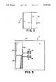
- FIG. 5is a bottom plan view of the security tag of FIG. 4.
- FIGS. 4 and 5there is shown in FIGS. 4 and 5 a preferred embodiment of a security tag or tag 10 in accordance with the present invention.
- the tag 10is generally of a type which is well known in the art of electronic security systems and, as is also well known in the art, is adapted to be secured to or otherwise borne by an article or item of personal property, or the packaging of such article (not shown), for which security or surveillance is sought.
- the tag 10may be secured to the article or its packaging at a retail or other such facility or may be secured to or incorporated into the article or its packaging by the manufacturer.
- the tag 10is comprised of an insulative substrate 12 fabricated of a material well known in the art having predetermined insulative and dielectric characteristics.
- the tag 10as shown in FIGS. 4 and 5, is comprised of circuitry means for initially establishing a resonant circuit 14 (hereinafter described in greater detail) by forming predetermined circuit elements which will hereinafter be described.
- the circuit elementsare formed by the combination of a first conductive pattern 16 imposed on a first or front surface 18 of the substrate 12 and a second conductive pattern 20 on the opposite or rear surface 22 of the substrate 12.
- the conductive patterns 16 and 18are formed on the front and rear surfaces 18, 20 of the substrate 12 utilizing electrically conductive materials of a known type, such as aluminum, in a manner which is well known in the electronic article surveillance art and which is described in detail in U.S. Pat. No. 3,913,219 entitled, "Planar Circuit Fabrication Process,” which is incorporated herein by reference. It will, of course, be appreciated by those skilled in the art that the particular conductive patterns 16 and 20 shown in FIGS. 4 and 5 are only for the purpose of illustrating a presently preferred embodiment of the invention and that numerous other conductive patterns may be developed as alternative embodiments of the invention. Similarly, while it is presently preferred that the known materials and methods set forth in the above-referenced U.S. Pat. No.
- the security tag 10is for use with an electronic security system (not shown) employed to provide article security for a controlled area.
- the security systemincludes a transmitter means or transmitter (not shown), of a type well known in the art, for transmitting into the controlled area electromagnetic energy, preferably radio frequency energy, within a predetermined detection frequency, preferably at about 8.2 Mhz.
- the electronic security systemfurther includes a receiver means or receiver (not shown), also of a type well known in the art, for detecting the presence of a tag resonating within the controlled area in response to the transmitted electromagnetic energy.
- Electronic security systems of this typeare generally well known in the art and are commercially available from several manufacturers, including Checkpoint Systems, Inc., the assignee of the present invention.
- the tag 10is comprised of circuitry means or electrical circuitry for initially establishing a resonant circuit 14 which is schematically illustrated by FIG. 1.
- the resonant circuit 14is comprised of an inductance component or inductor L which is connected in parallel with a first capacitance branch 24 and with a second capacitance branch 26.
- the first capacitance branch 24includes a first capacitor C1 connected in series with a second capacitor C2.
- the second capacitance branch 26includes a third capacitor C3 connected in series with a fourth capacitor C4.
- the inductor Lis formed by the coiled portion 28 of the first conductive pattern 16 on the front tag surface 18 (FIG. 4).
- capacitors C1 and C3are formed by the large aligned plates 30 of the first conductive pattern 16 and 32 of the second conductive pattern 20 on the rear tag surface 22.
- Capacitors C2 and C4are formed by the smaller aligned plates 34 of the first conductive pattern 16 and 36 of the second conductive pattern 20.
- the size or values of the inductor L and the four capacitors C1, C2, C3 and C4are determined based upon the desired resonant frequencies of the resonant circuit 14 and the need to maintain a low induced voltage across the plates of the capacitors.
- capacitor C1 and C3are selected to be much larger than capacitors C2 and C4 so that the primary voltage drop in each capacitance branch 24, 26 appears across capacitors C2 and C4.
- fis the resonant frequency of the circuit
- Lis the total inductance
- Cis the total capacitance
- the resonant frequencyis established by the following formula: ##EQU2##
- the first resonating frequency (f 1 ) of the resonant circuit 14 in its initial configuration as shown in FIG. 1,is selected to be within a first frequency range which is outside of the detection frequency range of the electronic security system with which the tag 10 is to be employed.
- the preferred frequency for the electronic security systemwill be assumed to be 8.2 MHz.
- the values of the inductor L and the four capacitors C1, C2, C3, C4are, for purposes of illustrating the invention, are selected to provide a first resonant frequency of about 16 Mhz.
- the resonant frequency of the resonant circuit 14is established to be at a first resonating frequency (16 MHz) which is above or outside of the detection frequency range. Accordingly, if the resonant circuit 14 illustrated in FIG. 1 is placed within the controlled area of an electronic security system operating at a detection frequency of 8.2 MHz, the resonant circuit 14 does not resonate and, therefore, a security tag 10 having such a resonant circuit is ineffective. In this manner, a tag 10 which is secured to an article by the article manufacturer, and which is not activated as described below, does not generate an alarm when passing through a security system.
- first meansare provided for making the change in the resonating frequency.
- the first meanspreferably comprises one of the second and fourth capacitors C2, C4, each of which includes fusing means for short-circuiting the plates of the capacitor when exposed to electromagnetic energy within the first frequency range, preferably at about 16 MHz.
- the fusing meanscomprises placing an indentation or "dimple" 38 on the conductive pattern portions 36 on the rear tag surface 22, employed for establishing capacitors C2 and C4.
- indentations or dimplesis well known in the art and is exemplified by U.S. Pat. No. 4,498,076, the disclosure of which is incorporated herein by reference.
- the second resonant frequency (f 2 )is within the detection frequency range and, preferably, is about 8.2 Mhz.
- the activated tag 10 having a resonant circuit 14', as illustrated in FIG. 2can be employed in connection with an electronic security system of the type described above and is effective for its normal intended use in detecting and identifying the presence of articles to which a tag 10 has been secured which are placed within the controlled area of the security system.
- the tag 10includes a second means for changing the resonating frequency of the resonant circuit 14' to a third frequency (f 3 ) within a third frequency range which is also outside of the detection frequency range.
- the second meanscomprises the other of the second and fourth capacitors C2 and C4 and, in the embodiment illustrated in FIG. 2, comprises the second capacitor C2.
- Exposing the activated tag 10 to the detection frequency with at least a predetermined minimum power levelresults in a buildup of induced voltage between the plates of capacitor C2 and, due to the dimple 38 diminishing the dielectric between the capacitor plates, capacitor C2 breaks down and short-circuits, thereby eliminating capacitor C2 from the resonant circuit and effectively establishing a new resonant circuit 14", illustrated in FIG. 3.
- the resonant frequency (f 3 ) of resonant circuit 14"is preferably below the detection frequency range (on the order of 6 MHz), and is determined by the following formula: ##EQU4##
- a security tag 10Once a security tag 10 has been deactivated as described above, it can be exposed to a source of electromagnetic energy within the third frequency range and preferably at the third resonant frequency (f 3 ). If the tag 10 resonates at the third resonating frequency (f 3 ), as determined by a suitable receiver, this will confirm that the tag 10 has effectively been deactivated and, therefore, cannot resonate at the detection frequency. In this manner, the tag 10 no longer interacts with the electronic security system and, therefore, accidental or false security alarms are effectively avoided.
- the present inventioncomprises an activatable/deactivatable security tag for use with an electronic security system. It will be recognized by those skilled in the art that changes may be made to the above-described embodiment of the invention without departing from the broad inventive concepts thereof. It is understood, therefore, that this invention is not limited to the particular embodiment disclosed, but is intended to cover any modifications which are within the scope and spirit of the invention as defined by the appended claims.
Landscapes
- Physics & Mathematics (AREA)
- General Physics & Mathematics (AREA)
- Engineering & Computer Science (AREA)
- Automation & Control Theory (AREA)
- Computer Security & Cryptography (AREA)
- Electromagnetism (AREA)
- Burglar Alarm Systems (AREA)
- Radar Systems Or Details Thereof (AREA)
Abstract
Description
Claims (9)
Priority Applications (16)
| Application Number | Priority Date | Filing Date | Title |
|---|---|---|---|
| US07/544,703US5103210A (en) | 1990-06-27 | 1990-06-27 | Activatable/deactivatable security tag for use with an electronic security system |
| DK90123960.8TDK0463233T3 (en) | 1990-06-27 | 1990-12-12 | Activable and deactivable fuse for use in an electronic fuse system |
| EP90123960AEP0463233B1 (en) | 1990-06-27 | 1990-12-12 | Activatable/deactivatable security tag for use with an electronic security system |
| ES90123960TES2057342T3 (en) | 1990-06-27 | 1990-12-12 | ACTIVATED / DEACTIVATED SECURITY LABEL FOR USE WITH AN ELECTRONIC SECURITY SYSTEM. |
| AT90123960TATE109913T1 (en) | 1990-06-27 | 1990-12-12 | ACTIVABLE/DEACTIVABLE SECURITY LABEL FOR USE WITH AN ELECTRONIC SECURITY SYSTEM. |
| DE69011512TDE69011512T2 (en) | 1990-06-27 | 1990-12-12 | Activatable / deactivatable security label for use with an electronic security system. |
| JP3511223AJP3030082B2 (en) | 1990-06-27 | 1991-05-29 | Selectable active and inactive security tags for use with electronic security systems |
| KR1019920700390AKR100218814B1 (en) | 1990-06-27 | 1991-05-29 | Activatable/deactivatable security tag for use with an electronic security system |
| AU80790/91AAU638589B2 (en) | 1990-06-27 | 1991-05-29 | Activatable-deactivatable security tag for use with an electronic security system |
| CA002064001ACA2064001C (en) | 1990-06-27 | 1991-05-29 | Activatable/deactivatable security tag for use with an electronic security system |
| PCT/US1991/003798WO1992000578A1 (en) | 1990-06-27 | 1991-05-29 | Activatable-deactivatable security tag for use with an electronic security system |
| NZ238410ANZ238410A (en) | 1990-06-27 | 1991-06-05 | Transponder security tag with switchable resonant frequencies |
| IE223291AIE62518B1 (en) | 1990-06-27 | 1991-06-26 | Activatable/Deactivatable Security Tag for Use With An Electronic Security System |
| AR91320051AAR244012A1 (en) | 1990-06-27 | 1991-06-27 | Activatable/deactivatable security tag for use with an electronic security system |
| FI920695AFI108968B (en) | 1990-06-27 | 1992-02-18 | In an electronic security system usable activating / deactivating safety tag |
| NO920673ANO920673D0 (en) | 1990-06-27 | 1992-02-20 | ACTIVABLE / DISABLABLE SECURITY LABEL FOR USE WITH AN ELECTRONIC SECURITY SYSTEM |
Applications Claiming Priority (1)
| Application Number | Priority Date | Filing Date | Title |
|---|---|---|---|
| US07/544,703US5103210A (en) | 1990-06-27 | 1990-06-27 | Activatable/deactivatable security tag for use with an electronic security system |
Publications (1)
| Publication Number | Publication Date |
|---|---|
| US5103210Atrue US5103210A (en) | 1992-04-07 |
Family
ID=24173230
Family Applications (1)
| Application Number | Title | Priority Date | Filing Date |
|---|---|---|---|
| US07/544,703Expired - LifetimeUS5103210A (en) | 1990-06-27 | 1990-06-27 | Activatable/deactivatable security tag for use with an electronic security system |
Country Status (16)
| Country | Link |
|---|---|
| US (1) | US5103210A (en) |
| EP (1) | EP0463233B1 (en) |
| JP (1) | JP3030082B2 (en) |
| KR (1) | KR100218814B1 (en) |
| AR (1) | AR244012A1 (en) |
| AT (1) | ATE109913T1 (en) |
| AU (1) | AU638589B2 (en) |
| CA (1) | CA2064001C (en) |
| DE (1) | DE69011512T2 (en) |
| DK (1) | DK0463233T3 (en) |
| ES (1) | ES2057342T3 (en) |
| FI (1) | FI108968B (en) |
| IE (1) | IE62518B1 (en) |
| NO (1) | NO920673D0 (en) |
| NZ (1) | NZ238410A (en) |
| WO (1) | WO1992000578A1 (en) |
Cited By (74)
| Publication number | Priority date | Publication date | Assignee | Title |
|---|---|---|---|---|
| US5182544A (en)* | 1991-10-23 | 1993-01-26 | Checkpoint Systems, Inc. | Security tag with electrostatic protection |
| WO1993005486A1 (en)* | 1991-09-09 | 1993-03-18 | Checkpoint Systems, Inc. | Binary encoded multiple frequency rf identification tag |
| US5444223A (en)* | 1994-01-11 | 1995-08-22 | Blama; Michael J. | Radio frequency identification tag and method |
| DE4416982A1 (en)* | 1994-05-13 | 1995-11-16 | Ese Elektronische Sicherungsan | Electronic goods security oscillating circuit |
| US5508684A (en)* | 1995-03-02 | 1996-04-16 | Becker; Richard S. | Article tag |
| US5510770A (en)* | 1994-03-30 | 1996-04-23 | Checkpoint Systems, Inc. | Surface deactivateable tag |
| US5517195A (en)* | 1994-09-14 | 1996-05-14 | Sensormatic Electronics Corporation | Dual frequency EAS tag with deactivation coil |
| US5574431A (en)* | 1995-08-29 | 1996-11-12 | Checkpoint Systems, Inc. | Deactivateable security tag |
| US5589820A (en)* | 1993-10-05 | 1996-12-31 | Pac/Scan, Inc. | Retail theft prevention and information device |
| US5608380A (en)* | 1994-05-18 | 1997-03-04 | N.V. Nederlandsche Apparatenfabriek Nedap | Deactivation and coding system for a contactless antitheft or identification label |
| US5650596A (en)* | 1994-08-05 | 1997-07-22 | Surgical Resources, L.L.C. | Automatic surgical sponge counter and blood loss determination system |
| US5680106A (en)* | 1995-10-27 | 1997-10-21 | International Business Machines Corporation | Multibit tag with stepwise variable frequencies |
| US5708419A (en)* | 1996-07-22 | 1998-01-13 | Checkpoint Systems, Inc. | Method of wire bonding an integrated circuit to an ultraflexible substrate |
| US5734327A (en)* | 1992-11-27 | 1998-03-31 | Dutch A & A Trading B.V. | Detection tag |
| US5754110A (en)* | 1996-03-07 | 1998-05-19 | Checkpoint Systems, Inc. | Security tag and manufacturing method |
| US5757521A (en)* | 1995-05-11 | 1998-05-26 | Advanced Deposition Technologies, Inc. | Pattern metallized optical varying security devices |
| US5841350A (en)* | 1997-06-27 | 1998-11-24 | Checkpoint Systems, Inc. | Electronic security tag useful in electronic article indentification and surveillance system |
| US5883582A (en)* | 1997-02-07 | 1999-03-16 | Checkpoint Systems, Inc. | Anticollision protocol for reading multiple RFID tags |
| US5923001A (en)* | 1994-08-05 | 1999-07-13 | Surgical Resources, L.L.C. | Automatic surgical sponge counter and blood loss determination system |
| US5990791A (en)* | 1997-10-22 | 1999-11-23 | William B. Spargur | Anti-theft detection system |
| WO2000002173A1 (en)* | 1998-07-06 | 2000-01-13 | Sensormatic Electronics Corporation | Energizing circuit for eas marker deactivation device |
| US6050622A (en)* | 1991-12-19 | 2000-04-18 | Gustafson; Ake | Safety sealing device |
| US6091607A (en)* | 1998-12-10 | 2000-07-18 | Checkpoint Systems, Inc. | Resonant tag with a conductive composition closing an electrical circuit |
| US6104311A (en)* | 1996-08-26 | 2000-08-15 | Addison Technologies | Information storage and identification tag |
| US6181248B1 (en)* | 1995-11-29 | 2001-01-30 | N.V. Nederlandsche Apparatenfabriek Nedap | Deactivatable article security label with data carrier function |
| US6232878B1 (en)* | 1999-05-20 | 2001-05-15 | Checkpoint Systems, Inc. | Resonant circuit detection, measurement and deactivation system employing a numerically controlled oscillator |
| US6287253B1 (en) | 1999-06-25 | 2001-09-11 | Sabolich Research & Development | Pressure ulcer condition sensing and monitoring |
| US6304169B1 (en) | 1997-01-02 | 2001-10-16 | C. W. Over Solutions, Inc. | Inductor-capacitor resonant circuits and improved methods of using same |
| US6400271B1 (en) | 2000-03-20 | 2002-06-04 | Checkpoint Systems, Inc. | Activate/deactiveable security tag with enhanced electronic protection for use with an electronic security system |
| US20040031626A1 (en)* | 1994-08-05 | 2004-02-19 | Morris Sharon L. | Automatic surgical sponge counter and blood loss determination system |
| US20040263319A1 (en)* | 2003-06-30 | 2004-12-30 | Nokia Corporation | System and method for supporting multiple reader-tag configurations using multi-mode radio frequency tag |
| US20050187837A1 (en)* | 2004-02-23 | 2005-08-25 | Eric Eckstein | Method and system for determining billing information in a tag fabrication process |
| US20050183817A1 (en)* | 2004-02-23 | 2005-08-25 | Eric Eckstein | Security tag system for fabricating a tag including an integrated surface processing system |
| US20050184873A1 (en)* | 2004-02-23 | 2005-08-25 | Eric Eckstein | Tag having patterned circuit elements and a process for making same |
| US20050183264A1 (en)* | 2004-02-23 | 2005-08-25 | Eric Eckstein | Method for aligning capacitor plates in a security tag and a capacitor formed thereby |
| US20050184872A1 (en)* | 2004-02-23 | 2005-08-25 | Clare Thomas J. | Identification marking and method for applying the identification marking to an item |
| US20050201450A1 (en)* | 2004-03-03 | 2005-09-15 | Volpi John P. | Interrogator and interrogation system employing the same |
| US20050280504A1 (en)* | 2004-06-22 | 2005-12-22 | Vubiq Incorporated, A Nevada Corporation | RFID system utilizing parametric reflective technology |
| US20060017545A1 (en)* | 2004-03-26 | 2006-01-26 | Volpi John P | Radio frequency identification interrogation systems and methods of operating the same |
| US20060077036A1 (en)* | 2004-09-29 | 2006-04-13 | Roemerman Steven D | Interrogation system employing prior knowledge about an object to discern an identity thereof |
| US20060116602A1 (en)* | 2004-12-01 | 2006-06-01 | Alden Dana A | Medical sensing device and system |
| US20060125637A1 (en)* | 2004-11-30 | 2006-06-15 | Canon Kabushiki Kaisha | Radio frequency tag |
| US20060132288A1 (en)* | 2004-11-30 | 2006-06-22 | Canon Kabushiki Kaisha | Method of reading information from RF tag and method of writing information therein |
| US20060187046A1 (en)* | 2005-02-22 | 2006-08-24 | Kramer Bradley A | System and method for killing a RFID tag |
| US20060202827A1 (en)* | 2003-03-03 | 2006-09-14 | Volpi John P | Interrogator and interrogation system employing the same |
| US20060220856A1 (en)* | 2005-04-01 | 2006-10-05 | Cisco Technology, Inc. | Dynamic and hybrid RFID |
| US20070012775A1 (en)* | 2004-02-23 | 2007-01-18 | Checkpoint Systems, Inc. | Method of fabricating a security tag in an integrated surface processing system |
| US20070222611A1 (en)* | 2000-04-26 | 2007-09-27 | Micron Technology, Inc. | Automated antenna trim for transmitting and receiving semiconductor devices |
| US20080018468A1 (en)* | 2003-03-03 | 2008-01-24 | Volpi John P | Interrogator and Interrogation System Employing the Same |
| US20080018450A1 (en)* | 2003-03-03 | 2008-01-24 | Volpi John P | Interrogator and Interrogation System Employing the Same |
| US20080018469A1 (en)* | 2003-03-03 | 2008-01-24 | Volpi John P | Interrogator and Interrogation System Employing the Same |
| US20080018432A1 (en)* | 2003-03-03 | 2008-01-24 | Volpi John P | Interrogator and Interrogation System Employing the Same |
| US20080024276A1 (en)* | 2003-03-03 | 2008-01-31 | Volpi John P | Interrogator and Interrogation System Employing the Same |
| US20080024277A1 (en)* | 2003-03-03 | 2008-01-31 | Volpi John P | Interrogator and Interrogation System Employing the Same |
| US20080237341A1 (en)* | 2006-09-13 | 2008-10-02 | Clearcount Medical Solutions, Inc. | Apparatus and methods for monitoring objects in a surgical field |
| US20080278336A1 (en)* | 2002-10-02 | 2008-11-13 | Orthocare Innovations Llc | Active on-patient sensor, method and system |
| US20090045917A1 (en)* | 2007-08-13 | 2009-02-19 | Volpi John P | Interrogator and Interrogation System Employing the Same |
| US7703691B2 (en) | 2005-03-16 | 2010-04-27 | Cisco Technology, Inc. | Multiple device and/or user association |
| US20110084814A1 (en)* | 2009-10-08 | 2011-04-14 | Checkpoint Systems, Inc. | Security tag utilizing rfid reflectivity mode power rationing |
| US20110181484A1 (en)* | 2007-06-22 | 2011-07-28 | Vubiq, Inc. | Integrated antenna and chip package and method of manufacturing thereof |
| US8385461B1 (en) | 2009-04-20 | 2013-02-26 | Vubiq, Inc. | On-off keying using vector modulation |
| US8542717B2 (en) | 2003-03-03 | 2013-09-24 | Veroscan, Inc. | Interrogator and interrogation system employing the same |
| US20140027159A1 (en)* | 2012-07-27 | 2014-01-30 | Johnson Electric S.A. | Security wrap |
| US20140033331A1 (en)* | 2012-07-27 | 2014-01-30 | Johnson Electric S.A. | Multilayer security wrap |
| US9035774B2 (en) | 2011-04-11 | 2015-05-19 | Lone Star Ip Holdings, Lp | Interrogator and system employing the same |
| US9088058B2 (en) | 2009-08-19 | 2015-07-21 | Vubiq Networks, Inc. | Waveguide interface with a launch transducer and a circular interface plate |
| US10320047B2 (en) | 2009-08-19 | 2019-06-11 | Vubiq Networks, Inc. | Waveguide assembly comprising a molded waveguide interface having a support block for a launch transducer that is coupled to a communication device through a flange attached to the interface |
| US20190206161A1 (en)* | 2013-06-21 | 2019-07-04 | X-Card Holdings, Llc | Electronic credential signal activation systems and methods |
| US10380857B1 (en)* | 2018-03-05 | 2019-08-13 | Sensormatic Electronics, LLC | Systems and methods for radio frequency identification enabled deactivation of acousto-magnetic ferrite based marker |
| US10818997B2 (en) | 2017-12-29 | 2020-10-27 | Vubiq Networks, Inc. | Waveguide interface and printed circuit board launch transducer assembly and methods of use thereof |
| US11216625B2 (en) | 2018-12-05 | 2022-01-04 | Vubiq Networks, Inc. | High bit density millimeter wave RFID systems, devices, and methods of use thereof |
| US11488459B2 (en) | 2016-12-29 | 2022-11-01 | Avery Dennison Retail Information Services, Llc | Dual function strap for resonating elements and ultra high frequency antennas |
| USD1051399S1 (en) | 2021-02-26 | 2024-11-12 | Stryker Corporation | Reader cradle for a surgical stand |
| US20250156658A1 (en)* | 2023-11-14 | 2025-05-15 | International Business Machines Corporation | Secure radio-frequency identification system |
Families Citing this family (9)
| Publication number | Priority date | Publication date | Assignee | Title |
|---|---|---|---|---|
| US5241299A (en)* | 1991-05-22 | 1993-08-31 | Checkpoint Systems, Inc. | Stabilized resonant tag circuit |
| DK167829B1 (en)* | 1991-11-14 | 1993-12-20 | Poul Richter Joergensen | PROCEDURE AND APPARATUS FOR ACTIVATING AND DISABLING LABELS |
| EP0670562A1 (en)* | 1994-03-01 | 1995-09-06 | Flexcon Company Inc. | Resonant tag label detection system and method utilizing multiple frequency response |
| US5852856A (en)* | 1997-11-13 | 1998-12-29 | Seidel; Stuart T. | Anti theft ink tag |
| CN100458836C (en)* | 2002-04-30 | 2009-02-04 | Nxp股份有限公司 | Method of securing a deactivation of a RFID transponder |
| RU2226001C2 (en)* | 2002-05-20 | 2004-03-20 | Центральный физико-технический институт Министерства обороны Российской Федерации | Method for protecting areas and objects against unauthorized invasion |
| EP1807814A1 (en)* | 2004-11-05 | 2007-07-18 | Qinetiq Limited | Detunable rf tags |
| CH700988A2 (en)* | 2009-05-15 | 2010-11-15 | Peter Grosse | Marking part of a system part. |
| WO2014192296A1 (en)* | 2013-05-31 | 2014-12-04 | パナソニックIpマネジメント株式会社 | Variable reactance circuit |
Citations (20)
| Publication number | Priority date | Publication date | Assignee | Title |
|---|---|---|---|---|
| US3624631A (en)* | 1970-04-27 | 1971-11-30 | Sanders Associates Inc | Pilferage control system |
| US3810147A (en)* | 1971-12-30 | 1974-05-07 | G Lichtblau | Electronic security system |
| US3913219A (en)* | 1974-05-24 | 1975-10-21 | Lichtblau G J | Planar circuit fabrication process |
| US3967161A (en)* | 1972-06-14 | 1976-06-29 | Lichtblau G J | A multi-frequency resonant tag circuit for use with an electronic security system having improved noise discrimination |
| US4498076A (en)* | 1982-05-10 | 1985-02-05 | Lichtblau G J | Resonant tag and deactivator for use in an electronic security system |
| US4598276A (en)* | 1983-11-16 | 1986-07-01 | Minnesota Mining And Manufacturing Company | Distributed capacitance LC resonant circuit |
| US4670740A (en)* | 1985-11-04 | 1987-06-02 | Security Tag Systems, Inc. | Portable, batteryless, frequency divider consisting of inductor and diode |
| US4692744A (en)* | 1985-01-04 | 1987-09-08 | Hickman James A A | Glazing unit alarm systems |
| US4694283A (en)* | 1981-10-30 | 1987-09-15 | Reeb Max E | Identification device in the form of a tag-like strip affixable to an article |
| US4720701A (en)* | 1986-01-02 | 1988-01-19 | Lichtblau G J | System with enhanced signal detection and discrimination with saturable magnetic marker |
| US4728938A (en)* | 1986-01-10 | 1988-03-01 | Checkpoint Systems, Inc. | Security tag deactivation system |
| US4745401A (en)* | 1985-09-09 | 1988-05-17 | Minnesota Mining And Manufacturing Company | RF reactivatable marker for electronic article surveillance system |
| US4774504A (en)* | 1987-06-22 | 1988-09-27 | Monarch Marking Systems, Inc. | EAS tag with helical coil |
| US4792790A (en)* | 1982-06-07 | 1988-12-20 | Reeb Max E | Identification device in the form of a tag-like strip affixable to an article and method for its manufacture |
| US4831363A (en)* | 1986-07-17 | 1989-05-16 | Checkpoint Systems, Inc. | Article security system |
| US4835524A (en)* | 1987-12-17 | 1989-05-30 | Checkpoint System, Inc. | Deactivatable security tag |
| US4864280A (en)* | 1987-02-17 | 1989-09-05 | N. V. Netherlandsche Apparatenfabriek Nedap | Flexible detection label |
| US4882569A (en)* | 1988-07-26 | 1989-11-21 | Security Tag Systems, Inc. | Deactivatable fequency-dividing-transponder tag |
| US4910499A (en)* | 1986-09-29 | 1990-03-20 | Monarch Marking Systems, Inc. | Tag and method of making same |
| US4920335A (en)* | 1989-01-31 | 1990-04-24 | Interamerican Industrial Company | Electronic article surveillance device with remote deactivation |
Family Cites Families (3)
| Publication number | Priority date | Publication date | Assignee | Title |
|---|---|---|---|---|
| US4021705A (en)* | 1975-03-24 | 1977-05-03 | Lichtblau G J | Resonant tag circuits having one or more fusible links |
| JPS61501947A (en)* | 1984-04-23 | 1986-09-04 | リヒトブラウ ジョージ ジェイ | Electronically detectable and deactivable signs and electronic safety devices using such signs |
| CH672854A5 (en)* | 1987-03-01 | 1989-12-29 | Scanmatic Security Systems Ag | Security tag for controlled access to building - has LC circuit with capacitor set to valve by burn in at specific location |
- 1990
- 1990-06-27USUS07/544,703patent/US5103210A/ennot_activeExpired - Lifetime
- 1990-12-12ESES90123960Tpatent/ES2057342T3/ennot_activeExpired - Lifetime
- 1990-12-12DEDE69011512Tpatent/DE69011512T2/ennot_activeExpired - Fee Related
- 1990-12-12ATAT90123960Tpatent/ATE109913T1/ennot_activeIP Right Cessation
- 1990-12-12DKDK90123960.8Tpatent/DK0463233T3/enactive
- 1990-12-12EPEP90123960Apatent/EP0463233B1/ennot_activeExpired - Lifetime
- 1991
- 1991-05-29CACA002064001Apatent/CA2064001C/ennot_activeExpired - Fee Related
- 1991-05-29JPJP3511223Apatent/JP3030082B2/ennot_activeExpired - Fee Related
- 1991-05-29KRKR1019920700390Apatent/KR100218814B1/ennot_activeExpired - Fee Related
- 1991-05-29WOPCT/US1991/003798patent/WO1992000578A1/enactiveIP Right Grant
- 1991-05-29AUAU80790/91Apatent/AU638589B2/ennot_activeCeased
- 1991-06-05NZNZ238410Apatent/NZ238410A/enunknown
- 1991-06-26IEIE223291Apatent/IE62518B1/ennot_activeIP Right Cessation
- 1991-06-27ARAR91320051Apatent/AR244012A1/enactive
- 1992
- 1992-02-18FIFI920695Apatent/FI108968B/ennot_activeIP Right Cessation
- 1992-02-20NONO920673Apatent/NO920673D0/enunknown
Patent Citations (21)
| Publication number | Priority date | Publication date | Assignee | Title |
|---|---|---|---|---|
| US3624631A (en)* | 1970-04-27 | 1971-11-30 | Sanders Associates Inc | Pilferage control system |
| US3810147A (en)* | 1971-12-30 | 1974-05-07 | G Lichtblau | Electronic security system |
| US3967161A (en)* | 1972-06-14 | 1976-06-29 | Lichtblau G J | A multi-frequency resonant tag circuit for use with an electronic security system having improved noise discrimination |
| US3913219A (en)* | 1974-05-24 | 1975-10-21 | Lichtblau G J | Planar circuit fabrication process |
| US4694283A (en)* | 1981-10-30 | 1987-09-15 | Reeb Max E | Identification device in the form of a tag-like strip affixable to an article |
| US4498076A (en)* | 1982-05-10 | 1985-02-05 | Lichtblau G J | Resonant tag and deactivator for use in an electronic security system |
| US4567473A (en)* | 1982-05-10 | 1986-01-28 | Lichtblau G J | Resonant tag and deactivator for use in an electronic security system |
| US4792790A (en)* | 1982-06-07 | 1988-12-20 | Reeb Max E | Identification device in the form of a tag-like strip affixable to an article and method for its manufacture |
| US4598276A (en)* | 1983-11-16 | 1986-07-01 | Minnesota Mining And Manufacturing Company | Distributed capacitance LC resonant circuit |
| US4692744A (en)* | 1985-01-04 | 1987-09-08 | Hickman James A A | Glazing unit alarm systems |
| US4745401A (en)* | 1985-09-09 | 1988-05-17 | Minnesota Mining And Manufacturing Company | RF reactivatable marker for electronic article surveillance system |
| US4670740A (en)* | 1985-11-04 | 1987-06-02 | Security Tag Systems, Inc. | Portable, batteryless, frequency divider consisting of inductor and diode |
| US4720701A (en)* | 1986-01-02 | 1988-01-19 | Lichtblau G J | System with enhanced signal detection and discrimination with saturable magnetic marker |
| US4728938A (en)* | 1986-01-10 | 1988-03-01 | Checkpoint Systems, Inc. | Security tag deactivation system |
| US4831363A (en)* | 1986-07-17 | 1989-05-16 | Checkpoint Systems, Inc. | Article security system |
| US4910499A (en)* | 1986-09-29 | 1990-03-20 | Monarch Marking Systems, Inc. | Tag and method of making same |
| US4864280A (en)* | 1987-02-17 | 1989-09-05 | N. V. Netherlandsche Apparatenfabriek Nedap | Flexible detection label |
| US4774504A (en)* | 1987-06-22 | 1988-09-27 | Monarch Marking Systems, Inc. | EAS tag with helical coil |
| US4835524A (en)* | 1987-12-17 | 1989-05-30 | Checkpoint System, Inc. | Deactivatable security tag |
| US4882569A (en)* | 1988-07-26 | 1989-11-21 | Security Tag Systems, Inc. | Deactivatable fequency-dividing-transponder tag |
| US4920335A (en)* | 1989-01-31 | 1990-04-24 | Interamerican Industrial Company | Electronic article surveillance device with remote deactivation |
Cited By (165)
| Publication number | Priority date | Publication date | Assignee | Title |
|---|---|---|---|---|
| WO1993005486A1 (en)* | 1991-09-09 | 1993-03-18 | Checkpoint Systems, Inc. | Binary encoded multiple frequency rf identification tag |
| US5218189A (en)* | 1991-09-09 | 1993-06-08 | Checkpoint Systems, Inc. | Binary encoded multiple frequency rf indentification tag |
| US5182544A (en)* | 1991-10-23 | 1993-01-26 | Checkpoint Systems, Inc. | Security tag with electrostatic protection |
| US6050622A (en)* | 1991-12-19 | 2000-04-18 | Gustafson; Ake | Safety sealing device |
| US5734327A (en)* | 1992-11-27 | 1998-03-31 | Dutch A & A Trading B.V. | Detection tag |
| US5589820A (en)* | 1993-10-05 | 1996-12-31 | Pac/Scan, Inc. | Retail theft prevention and information device |
| USRE37956E1 (en) | 1994-01-11 | 2003-01-07 | C. W. Over Solutions, Inc. | Radio frequency identification tag and method |
| US5444223A (en)* | 1994-01-11 | 1995-08-22 | Blama; Michael J. | Radio frequency identification tag and method |
| US5510770A (en)* | 1994-03-30 | 1996-04-23 | Checkpoint Systems, Inc. | Surface deactivateable tag |
| DE4416982A1 (en)* | 1994-05-13 | 1995-11-16 | Ese Elektronische Sicherungsan | Electronic goods security oscillating circuit |
| US5608380A (en)* | 1994-05-18 | 1997-03-04 | N.V. Nederlandsche Apparatenfabriek Nedap | Deactivation and coding system for a contactless antitheft or identification label |
| US8105296B2 (en) | 1994-08-05 | 2012-01-31 | Clearcount Medical Solutions, Inc. | Automatic surgical sponge counter and blood loss determination system |
| US5650596A (en)* | 1994-08-05 | 1997-07-22 | Surgical Resources, L.L.C. | Automatic surgical sponge counter and blood loss determination system |
| US20040031626A1 (en)* | 1994-08-05 | 2004-02-19 | Morris Sharon L. | Automatic surgical sponge counter and blood loss determination system |
| US8279068B2 (en) | 1994-08-05 | 2012-10-02 | Clearcount Medical Solutions, Inc. | Automatic surgical sponge counter and blood loss determination system |
| US8576076B2 (en) | 1994-08-05 | 2013-11-05 | Clearcount Medical Solutions, Inc. | Automatic surgical sponge counter and blood loss determination system |
| US5923001A (en)* | 1994-08-05 | 1999-07-13 | Surgical Resources, L.L.C. | Automatic surgical sponge counter and blood loss determination system |
| US6998541B2 (en) | 1994-08-05 | 2006-02-14 | Clearcount Medical Solutions, Inc. | Automatic surgical sponge counter and blood loss determination system |
| US20060044137A1 (en)* | 1994-08-05 | 2006-03-02 | Morris Sharon L | Automatic surgical sponge counter and blood loss determination system |
| US5517195A (en)* | 1994-09-14 | 1996-05-14 | Sensormatic Electronics Corporation | Dual frequency EAS tag with deactivation coil |
| US5508684A (en)* | 1995-03-02 | 1996-04-16 | Becker; Richard S. | Article tag |
| US5757521A (en)* | 1995-05-11 | 1998-05-26 | Advanced Deposition Technologies, Inc. | Pattern metallized optical varying security devices |
| US5574431A (en)* | 1995-08-29 | 1996-11-12 | Checkpoint Systems, Inc. | Deactivateable security tag |
| CN1098511C (en)* | 1995-08-29 | 2003-01-08 | 检验点系统公司 | Deactivateable security tag |
| US5680106A (en)* | 1995-10-27 | 1997-10-21 | International Business Machines Corporation | Multibit tag with stepwise variable frequencies |
| US6181248B1 (en)* | 1995-11-29 | 2001-01-30 | N.V. Nederlandsche Apparatenfabriek Nedap | Deactivatable article security label with data carrier function |
| US5754110A (en)* | 1996-03-07 | 1998-05-19 | Checkpoint Systems, Inc. | Security tag and manufacturing method |
| CN1120453C (en)* | 1996-03-07 | 2003-09-03 | 检验点系统公司 | Security tag and manufacturing method |
| US5708419A (en)* | 1996-07-22 | 1998-01-13 | Checkpoint Systems, Inc. | Method of wire bonding an integrated circuit to an ultraflexible substrate |
| US6104311A (en)* | 1996-08-26 | 2000-08-15 | Addison Technologies | Information storage and identification tag |
| US6304169B1 (en) | 1997-01-02 | 2001-10-16 | C. W. Over Solutions, Inc. | Inductor-capacitor resonant circuits and improved methods of using same |
| US6714120B2 (en) | 1997-01-02 | 2004-03-30 | C. W. Over Solutions, Inc. | Inductor-capacitor resonant circuits and improved methods of using same |
| US6111507A (en)* | 1997-02-03 | 2000-08-29 | Sensormatic Electronics Corporation | Energizing circuit for EAS marker deactivation device |
| US5883582A (en)* | 1997-02-07 | 1999-03-16 | Checkpoint Systems, Inc. | Anticollision protocol for reading multiple RFID tags |
| US5841350A (en)* | 1997-06-27 | 1998-11-24 | Checkpoint Systems, Inc. | Electronic security tag useful in electronic article indentification and surveillance system |
| US5990791A (en)* | 1997-10-22 | 1999-11-23 | William B. Spargur | Anti-theft detection system |
| WO2000002173A1 (en)* | 1998-07-06 | 2000-01-13 | Sensormatic Electronics Corporation | Energizing circuit for eas marker deactivation device |
| US6091607A (en)* | 1998-12-10 | 2000-07-18 | Checkpoint Systems, Inc. | Resonant tag with a conductive composition closing an electrical circuit |
| US6359562B2 (en) | 1999-05-20 | 2002-03-19 | Checkpoint Systems, Inc. | Resonant circuit detection measurement and deactivation system employing a numerically controlled oscillator |
| US6232878B1 (en)* | 1999-05-20 | 2001-05-15 | Checkpoint Systems, Inc. | Resonant circuit detection, measurement and deactivation system employing a numerically controlled oscillator |
| US6287253B1 (en) | 1999-06-25 | 2001-09-11 | Sabolich Research & Development | Pressure ulcer condition sensing and monitoring |
| US6400271B1 (en) | 2000-03-20 | 2002-06-04 | Checkpoint Systems, Inc. | Activate/deactiveable security tag with enhanced electronic protection for use with an electronic security system |
| US20070222611A1 (en)* | 2000-04-26 | 2007-09-27 | Micron Technology, Inc. | Automated antenna trim for transmitting and receiving semiconductor devices |
| US8134467B2 (en)* | 2000-04-26 | 2012-03-13 | Round Rock Research, Llc | Automated antenna trim for transmitting and receiving semiconductor devices |
| US20080278336A1 (en)* | 2002-10-02 | 2008-11-13 | Orthocare Innovations Llc | Active on-patient sensor, method and system |
| US8111165B2 (en) | 2002-10-02 | 2012-02-07 | Orthocare Innovations Llc | Active on-patient sensor, method and system |
| US8416088B2 (en) | 2002-10-02 | 2013-04-09 | Orthocare Innovations Llc | Active on-patient sensor, method and system |
| US8063760B2 (en) | 2003-03-03 | 2011-11-22 | Veroscan, Inc. | Interrogator and interrogation system employing the same |
| US20060202827A1 (en)* | 2003-03-03 | 2006-09-14 | Volpi John P | Interrogator and interrogation system employing the same |
| US7764178B2 (en) | 2003-03-03 | 2010-07-27 | Veroscan, Inc. | Interrogator and interrogation system employing the same |
| US8552869B2 (en) | 2003-03-03 | 2013-10-08 | Veroscan, Inc. | Interrogator and interrogation system employing the same |
| US8542717B2 (en) | 2003-03-03 | 2013-09-24 | Veroscan, Inc. | Interrogator and interrogation system employing the same |
| US7760097B2 (en) | 2003-03-03 | 2010-07-20 | Veroscan, Inc. | Interrogator and interrogation system employing the same |
| US7557711B2 (en) | 2003-03-03 | 2009-07-07 | Veroscan, Inc. | Interrogator and interrogation system employing the same |
| US20080024277A1 (en)* | 2003-03-03 | 2008-01-31 | Volpi John P | Interrogator and Interrogation System Employing the Same |
| US20080024276A1 (en)* | 2003-03-03 | 2008-01-31 | Volpi John P | Interrogator and Interrogation System Employing the Same |
| US7893840B2 (en) | 2003-03-03 | 2011-02-22 | Veroscan, Inc. | Interrogator and interrogation system employing the same |
| US20080018432A1 (en)* | 2003-03-03 | 2008-01-24 | Volpi John P | Interrogator and Interrogation System Employing the Same |
| US8174366B2 (en) | 2003-03-03 | 2012-05-08 | Veroscan, Inc. | Interrogator and interrogation system employing the same |
| US20080018469A1 (en)* | 2003-03-03 | 2008-01-24 | Volpi John P | Interrogator and Interrogation System Employing the Same |
| US7541933B2 (en) | 2003-03-03 | 2009-06-02 | Veroscan, Inc. | Interrogator and interrogation system employing the same |
| US20080018450A1 (en)* | 2003-03-03 | 2008-01-24 | Volpi John P | Interrogator and Interrogation System Employing the Same |
| US20080018468A1 (en)* | 2003-03-03 | 2008-01-24 | Volpi John P | Interrogator and Interrogation System Employing the Same |
| US20070216526A1 (en)* | 2003-03-03 | 2007-09-20 | Volpi John P | Interrogator and interrogation system employing the same |
| US7671744B2 (en) | 2003-03-03 | 2010-03-02 | Veroscan, Inc. | Interrogator and interrogation system employing the same |
| US7446646B2 (en)* | 2003-06-30 | 2008-11-04 | Nokia Corporation | System and method for supporting multiple reader-tag configurations using multi-mode radio frequency tag |
| US7868737B2 (en) | 2003-06-30 | 2011-01-11 | Nokia Corporation | System and method for supporting multiple reader-tag configurations using multi-mode radio frequency tag |
| US20040263319A1 (en)* | 2003-06-30 | 2004-12-30 | Nokia Corporation | System and method for supporting multiple reader-tag configurations using multi-mode radio frequency tag |
| US20090033498A1 (en)* | 2003-06-30 | 2009-02-05 | Heikki Huomo | System and Method for Supporting Multiple Reader-Tag Configurations Using Multi-Mode Radio Frequency Tag |
| US20050183817A1 (en)* | 2004-02-23 | 2005-08-25 | Eric Eckstein | Security tag system for fabricating a tag including an integrated surface processing system |
| US20050184873A1 (en)* | 2004-02-23 | 2005-08-25 | Eric Eckstein | Tag having patterned circuit elements and a process for making same |
| US20050187837A1 (en)* | 2004-02-23 | 2005-08-25 | Eric Eckstein | Method and system for determining billing information in a tag fabrication process |
| US20060185790A1 (en)* | 2004-02-23 | 2006-08-24 | Eric Eckstein | Security tag & method using a flowable material |
| US7368033B2 (en) | 2004-02-23 | 2008-05-06 | Checkpoint Systems, Inc. | Security tag and system for fabricating a tag including an integrated surface processing system |
| US7384496B2 (en) | 2004-02-23 | 2008-06-10 | Checkpoint Systems, Inc. | Security tag system for fabricating a tag including an integrated surface processing system |
| US8099335B2 (en) | 2004-02-23 | 2012-01-17 | Checkpoint Systems, Inc. | Method and system for determining billing information in a tag fabrication process |
| US7704346B2 (en) | 2004-02-23 | 2010-04-27 | Checkpoint Systems, Inc. | Method of fabricating a security tag in an integrated surface processing system |
| US20060175003A1 (en)* | 2004-02-23 | 2006-08-10 | Eric Eckstein | Security tag and system for fabricating a tag including an integrated surface processing system |
| US7116227B2 (en) | 2004-02-23 | 2006-10-03 | Checkpoint Systems, Inc. | Tag having patterned circuit elements and a process for making same |
| US20050183264A1 (en)* | 2004-02-23 | 2005-08-25 | Eric Eckstein | Method for aligning capacitor plates in a security tag and a capacitor formed thereby |
| US7119685B2 (en) | 2004-02-23 | 2006-10-10 | Checkpoint Systems, Inc. | Method for aligning capacitor plates in a security tag and a capacitor formed thereby |
| US7138919B2 (en) | 2004-02-23 | 2006-11-21 | Checkpoint Systems, Inc. | Identification marking and method for applying the identification marking to an item |
| US20070012775A1 (en)* | 2004-02-23 | 2007-01-18 | Checkpoint Systems, Inc. | Method of fabricating a security tag in an integrated surface processing system |
| US7856708B2 (en) | 2004-02-23 | 2010-12-28 | Checkpoint Systems, Inc. | Process for forming at least a portion of a package or an envelope bearing a printed indicia |
| US20050184872A1 (en)* | 2004-02-23 | 2005-08-25 | Clare Thomas J. | Identification marking and method for applying the identification marking to an item |
| US8948279B2 (en) | 2004-03-03 | 2015-02-03 | Veroscan, Inc. | Interrogator and interrogation system employing the same |
| US10628645B2 (en) | 2004-03-03 | 2020-04-21 | Medical Ip Holdings, Lp | Interrogator and interrogation system employing the same |
| US20050201450A1 (en)* | 2004-03-03 | 2005-09-15 | Volpi John P. | Interrogator and interrogation system employing the same |
| US11205058B2 (en) | 2004-03-03 | 2021-12-21 | Lone Star Scm Systems, Lp | Interrogator and interrogation system employing the same |
| US20090040025A1 (en)* | 2004-03-26 | 2009-02-12 | Volpi John P | Radio Frequency Identification Interrogation Systems and Methods of Operating The Same |
| US20060017545A1 (en)* | 2004-03-26 | 2006-01-26 | Volpi John P | Radio frequency identification interrogation systems and methods of operating the same |
| US20050280539A1 (en)* | 2004-06-22 | 2005-12-22 | Pettus Michael G | RFID system utilizing parametric reflective technology |
| US20050280504A1 (en)* | 2004-06-22 | 2005-12-22 | Vubiq Incorporated, A Nevada Corporation | RFID system utilizing parametric reflective technology |
| US7460014B2 (en) | 2004-06-22 | 2008-12-02 | Vubiq Incorporated | RFID system utilizing parametric reflective technology |
| US7498940B2 (en) | 2004-06-22 | 2009-03-03 | Vubiq, Inc. | RFID system utilizing parametric reradiated technology |
| US7501948B2 (en) | 2004-09-29 | 2009-03-10 | Lone Star Ip Holdings, Lp | Interrogation system employing prior knowledge about an object to discern an identity thereof |
| US20060077036A1 (en)* | 2004-09-29 | 2006-04-13 | Roemerman Steven D | Interrogation system employing prior knowledge about an object to discern an identity thereof |
| US20060125637A1 (en)* | 2004-11-30 | 2006-06-15 | Canon Kabushiki Kaisha | Radio frequency tag |
| US7817043B2 (en)* | 2004-11-30 | 2010-10-19 | Canon Kabushiki Kaisha | Radio frequency tag |
| US20060132288A1 (en)* | 2004-11-30 | 2006-06-22 | Canon Kabushiki Kaisha | Method of reading information from RF tag and method of writing information therein |
| US20060116602A1 (en)* | 2004-12-01 | 2006-06-01 | Alden Dana A | Medical sensing device and system |
| US20060187046A1 (en)* | 2005-02-22 | 2006-08-24 | Kramer Bradley A | System and method for killing a RFID tag |
| US7474211B2 (en)* | 2005-02-22 | 2009-01-06 | Bradley Allen Kramer | System and method for killing a RFID tag |
| WO2006091585A3 (en)* | 2005-02-22 | 2009-06-18 | Texas Instruments Inc | System and method for disabling an rfid tag |
| CN101523452B (en)* | 2005-02-22 | 2013-05-22 | 德州仪器公司 | System and method for disabling an RFID tag |
| US7703691B2 (en) | 2005-03-16 | 2010-04-27 | Cisco Technology, Inc. | Multiple device and/or user association |
| US7274291B2 (en)* | 2005-04-01 | 2007-09-25 | Cisco Technology, Inc. | Dynamic and hybrid RFID |
| US20060220856A1 (en)* | 2005-04-01 | 2006-10-05 | Cisco Technology, Inc. | Dynamic and hybrid RFID |
| WO2006107613A1 (en)* | 2005-04-01 | 2006-10-12 | Cisco Technology, Inc. | Dynamic and hybrid rfid |
| US20070279229A1 (en)* | 2005-04-01 | 2007-12-06 | Cisco Technology, Inc. | Dynamic and hybrid rfid |
| US7446657B2 (en) | 2005-04-01 | 2008-11-04 | Cisco Technology, Inc. | Dynamic and hybrid RFID |
| US9135669B2 (en) | 2005-09-29 | 2015-09-15 | Lone Star Ip Holdings, Lp | Interrogation system employing prior knowledge about an object to discern an identity thereof |
| US20090160605A1 (en)* | 2005-09-29 | 2009-06-25 | Roemerman Steven D | Interrogation System Employing Prior Knowledge About an Object to Discern an Identity Thereof |
| US20080237341A1 (en)* | 2006-09-13 | 2008-10-02 | Clearcount Medical Solutions, Inc. | Apparatus and methods for monitoring objects in a surgical field |
| US9974625B2 (en) | 2006-09-13 | 2018-05-22 | Stryker Combo L.L.C. | Apparatus and methods for monitoring objects in a surgical field |
| US8479989B2 (en) | 2006-09-13 | 2013-07-09 | Clearcount Medical Solutions, Inc. | Apparatus and methods for monitoring objects in a surgical field |
| US11090129B2 (en) | 2006-09-13 | 2021-08-17 | Stryker Corporation | Apparatus and methods for monitoring objects in a surgical field |
| US8256674B2 (en) | 2006-09-13 | 2012-09-04 | Clearcount Medical Solutions, Inc. | Apparatus and methods for monitoring objects in a surgical field |
| US8181860B2 (en) | 2006-09-13 | 2012-05-22 | Clearcount Medical Solutions, Inc. | Apparatus and methods for monitoring objects in a surgical field |
| US12357412B2 (en) | 2006-09-13 | 2025-07-15 | Stryker Corporation | Apparatus and methods for monitoring objects in a surgical field |
| US11963827B2 (en) | 2006-09-13 | 2024-04-23 | Stryker Corporation | Apparatus and methods for monitoring objects in a surgical field |
| US10729510B2 (en) | 2006-09-13 | 2020-08-04 | Stryker Corporation | Apparatus and methods for monitoring objects in a surgical field |
| US8985446B2 (en) | 2006-09-13 | 2015-03-24 | Stryker Combo L.L.C. | Apparatus and methods for monitoring objects in a surgical field |
| US11116598B1 (en) | 2006-09-13 | 2021-09-14 | Stryker Corporation | Apparatus and methods for monitoring objects in a surgical field |
| US9672397B2 (en) | 2006-09-13 | 2017-06-06 | Stryker Combo L.L.C. | Apparatus and methods for monitoring objects in a surgical field |
| US9530036B2 (en) | 2006-09-13 | 2016-12-27 | Stryker Combo L.L.C. | Methods for monitoring objects in a surgical field |
| US9414973B2 (en) | 2006-09-13 | 2016-08-16 | Stryker Combo L.L.C. | Apparatus and methods for monitoring objects in a surgical field |
| US11793591B2 (en) | 2006-09-13 | 2023-10-24 | Stryker Corporation | Apparatus and methods for monitoring objects in a surgical field |
| US20110181484A1 (en)* | 2007-06-22 | 2011-07-28 | Vubiq, Inc. | Integrated antenna and chip package and method of manufacturing thereof |
| US8477070B2 (en) | 2007-06-22 | 2013-07-02 | Vubiq, Inc. | Integrated antenna and chip package and method of manufacturing thereof |
| US20090045917A1 (en)* | 2007-08-13 | 2009-02-19 | Volpi John P | Interrogator and Interrogation System Employing the Same |
| US7755491B2 (en) | 2007-08-13 | 2010-07-13 | Veroscan, Inc. | Interrogator and interrogation system employing the same |
| US8385461B1 (en) | 2009-04-20 | 2013-02-26 | Vubiq, Inc. | On-off keying using vector modulation |
| US9088058B2 (en) | 2009-08-19 | 2015-07-21 | Vubiq Networks, Inc. | Waveguide interface with a launch transducer and a circular interface plate |
| US10320047B2 (en) | 2009-08-19 | 2019-06-11 | Vubiq Networks, Inc. | Waveguide assembly comprising a molded waveguide interface having a support block for a launch transducer that is coupled to a communication device through a flange attached to the interface |
| US20110084814A1 (en)* | 2009-10-08 | 2011-04-14 | Checkpoint Systems, Inc. | Security tag utilizing rfid reflectivity mode power rationing |
| US9470787B2 (en) | 2011-04-11 | 2016-10-18 | Lone Star Ip Holdings, Lp | Interrogator and system employing the same |
| US10324177B2 (en) | 2011-04-11 | 2019-06-18 | Lone Star Ip Holdings, Lp | Interrogator and system employing the same |
| US9035774B2 (en) | 2011-04-11 | 2015-05-19 | Lone Star Ip Holdings, Lp | Interrogator and system employing the same |
| US10670707B2 (en) | 2011-04-11 | 2020-06-02 | Lone Star Ip Holdings, Lp | Interrogator and system employing the same |
| US9209139B2 (en)* | 2012-07-27 | 2015-12-08 | Johnson Electric S.A. | Multilayer security wrap |
| US20140027159A1 (en)* | 2012-07-27 | 2014-01-30 | Johnson Electric S.A. | Security wrap |
| US20140033331A1 (en)* | 2012-07-27 | 2014-01-30 | Johnson Electric S.A. | Multilayer security wrap |
| US9224280B2 (en)* | 2012-07-27 | 2015-12-29 | Johnson Electric S.A. | Security wrap |
| US10964146B2 (en)* | 2013-06-21 | 2021-03-30 | X-Card Holdings, Llc | Electronic credential signal activation systems and methods |
| US12260695B2 (en) | 2013-06-21 | 2025-03-25 | X-Card Holdings, Llc | Electronic credential signal activation systems and methods |
| US20190206161A1 (en)* | 2013-06-21 | 2019-07-04 | X-Card Holdings, Llc | Electronic credential signal activation systems and methods |
| US11734979B2 (en) | 2013-06-21 | 2023-08-22 | X-Card Holdings, Llc | Electronic credential signal activation systems and methods |
| US11417162B2 (en) | 2013-06-21 | 2022-08-16 | X-Card Holdings, Llc | Electronic credential signal activation systems and methods |
| US11488459B2 (en) | 2016-12-29 | 2022-11-01 | Avery Dennison Retail Information Services, Llc | Dual function strap for resonating elements and ultra high frequency antennas |
| US11704985B2 (en) | 2016-12-29 | 2023-07-18 | Avery Dennison Retail Information Services Llc | Dual function strap for resonating elements and ultra high frequency antennas |
| US10818997B2 (en) | 2017-12-29 | 2020-10-27 | Vubiq Networks, Inc. | Waveguide interface and printed circuit board launch transducer assembly and methods of use thereof |
| US10380857B1 (en)* | 2018-03-05 | 2019-08-13 | Sensormatic Electronics, LLC | Systems and methods for radio frequency identification enabled deactivation of acousto-magnetic ferrite based marker |
| CN115294713A (en)* | 2018-03-05 | 2022-11-04 | 先讯美资电子有限责任公司 | RFID-enabled deactivation system and method for AM ferrite-based markers |
| US11699335B2 (en)* | 2018-03-05 | 2023-07-11 | Sensormatic Electronics, LLC | Systems and methods for Radio Frequency Identification enabled deactiviation of Acousto-Magnetic ferrite based marker |
| CN112041902B (en)* | 2018-03-05 | 2022-07-08 | 先讯美资电子有限责任公司 | RFID-enabled deactivation system and method for AM ferrite-based markers |
| US20230298447A1 (en)* | 2018-03-05 | 2023-09-21 | Sensormatic Electronics, LLC | Systems and methods for radio frequency identification enabled deactiviation of acousto-magnetic ferrite based marker |
| US20200043313A1 (en)* | 2018-03-05 | 2020-02-06 | Sensormatic Electronics, LLC | Systems and methods for radio frequency identification enabled deactivation of acousto-magnetic ferrite based marker |
| US20210233372A1 (en)* | 2018-03-05 | 2021-07-29 | Sensormatic Electronics, LLC | Systems and methods for radio frequency identification enabled deactiviation of acousto-magnetic ferrite based marker |
| US12136326B2 (en)* | 2018-03-05 | 2024-11-05 | Sensormatic Electronics, LLC | Systems and methods for radio frequency identification enabled deactivation of acousto-magnetic ferrite based marker |
| US11011037B2 (en)* | 2018-03-05 | 2021-05-18 | Sensormatic Electronics Llc | Systems and methods for radio frequency identification enabled deactivation of acousto-magnetic ferrite based marker |
| CN112041902A (en)* | 2018-03-05 | 2020-12-04 | 先讯美资电子有限责任公司 | RFID-enabled deactivation system and method for AM ferrite-based markers |
| US11216625B2 (en) | 2018-12-05 | 2022-01-04 | Vubiq Networks, Inc. | High bit density millimeter wave RFID systems, devices, and methods of use thereof |
| USD1051399S1 (en) | 2021-02-26 | 2024-11-12 | Stryker Corporation | Reader cradle for a surgical stand |
| US20250156658A1 (en)* | 2023-11-14 | 2025-05-15 | International Business Machines Corporation | Secure radio-frequency identification system |
Also Published As
| Publication number | Publication date |
|---|---|
| EP0463233A2 (en) | 1992-01-02 |
| JPH05501468A (en) | 1993-03-18 |
| DK0463233T3 (en) | 1994-12-19 |
| CA2064001C (en) | 2000-02-29 |
| NO920673L (en) | 1992-02-20 |
| IE62518B1 (en) | 1995-02-08 |
| CA2064001A1 (en) | 1991-12-28 |
| FI920695A0 (en) | 1992-02-18 |
| KR920702523A (en) | 1992-09-04 |
| AU8079091A (en) | 1992-01-23 |
| KR100218814B1 (en) | 1999-09-01 |
| ES2057342T3 (en) | 1994-10-16 |
| AU638589B2 (en) | 1993-07-01 |
| JP3030082B2 (en) | 2000-04-10 |
| NO920673D0 (en) | 1992-02-20 |
| EP0463233B1 (en) | 1994-08-10 |
| ATE109913T1 (en) | 1994-08-15 |
| DE69011512T2 (en) | 1995-01-05 |
| EP0463233A3 (en) | 1992-05-06 |
| WO1992000578A1 (en) | 1992-01-09 |
| AR244012A1 (en) | 1993-09-30 |
| IE912232A1 (en) | 1992-01-01 |
| NZ238410A (en) | 1993-06-25 |
| FI108968B (en) | 2002-04-30 |
| DE69011512D1 (en) | 1994-09-15 |
Similar Documents
| Publication | Publication Date | Title |
|---|---|---|
| US5103210A (en) | Activatable/deactivatable security tag for use with an electronic security system | |
| EP0550443B1 (en) | Security tag for compact disc storage container | |
| US4920335A (en) | Electronic article surveillance device with remote deactivation | |
| US5182544A (en) | Security tag with electrostatic protection | |
| US5081445A (en) | Method for tagging articles used in conjunction with an electronic article surveillance system, and tags or labels useful in connection therewith | |
| CA2184135C (en) | Deactivateable security tag | |
| US5276431A (en) | Security tag for use with article having inherent capacitance | |
| EP0774740B1 (en) | Tags or labels useful in connection with an electronic article surveillance system | |
| CA2496202C (en) | Deactivatable radio frequency security label | |
| Bhatt et al. | A Comparative Study of Electronic Article Surveillance (EAS) System |
Legal Events
| Date | Code | Title | Description |
|---|---|---|---|
| AS | Assignment | Owner name:CHECKPOINT SYSTEMS, INC., A CORP. OF COMMONWEALTH Free format text:ASSIGNMENT OF ASSIGNORS INTEREST.;ASSIGNORS:RODE, FRANCE;PICCOLI, ANTHONY F.;REEL/FRAME:005489/0498 Effective date:19900626 | |
| STCF | Information on status: patent grant | Free format text:PATENTED CASE | |
| REFU | Refund | Free format text:REFUND PROCESSED. MAINTENANCE FEE HAS ALREADY BEEN PAID (ORIGINAL EVENT CODE: R160); ENTITY STATUS OF PATENT OWNER: LARGE ENTITY | |
| FPAY | Fee payment | Year of fee payment:4 | |
| FPAY | Fee payment | Year of fee payment:8 | |
| AS | Assignment | Owner name:FIRST UNION NATIONAL BANK, AS ADMINISTRATIVE AGENT Free format text:GUARANTEE AND COLLATERAL AGREEMENT;ASSIGNOR:CHECKPOINT SYSTEMS, INC.;REEL/FRAME:010668/0049 Effective date:19991209 | |
| FPAY | Fee payment | Year of fee payment:12 | |
| AS | Assignment | Owner name:CHECKPOINT SYSTEMS, INC., NEW JERSEY Free format text:TERMINATION OF SECURITY INTEREST IN PATENTS;ASSIGNOR:WACHOVIA BANK, NATIONAL ASSOCIATION, FORMERLY KNOWN AS FIRST UNION NATIONAL BANK, AS ADMINISTRATIVE AGENT;REEL/FRAME:022562/0740 Effective date:20090413 | |
| AS | Assignment | Owner name:WACHOVIA BANK, NATIONAL ASSOCIATION, AS ADMINISTRA Free format text:NOTICE OF GRANT OF SECURITY INTEREST IN PATENTS;ASSIGNOR:CHECKPOINT SYSTEMS, INC.;REEL/FRAME:022634/0888 Effective date:20090430 | |
| AS | Assignment | Owner name:CHECKPOINT SYSTEMS, INC., NEW JERSEY Free format text:TERMINATION OF SECURITY INTEREST IN PATENTS;ASSIGNOR:WELLS FARGO BANK, NATIONAL ASSOCIATION, SUCCESSOR-BY-MERGER TO WACHOVIA BANK, NATIONAL ASSOCIATION, AS ADMINISTRATIVE AGENT;REEL/FRAME:024723/0187 Effective date:20100722 |