US5103202A - Ambient compensated circuit breaker - Google Patents
Ambient compensated circuit breakerDownload PDFInfo
- Publication number
- US5103202A US5103202AUS07/770,002US77000291AUS5103202AUS 5103202 AUS5103202 AUS 5103202AUS 77000291 AUS77000291 AUS 77000291AUS 5103202 AUS5103202 AUS 5103202A
- Authority
- US
- United States
- Prior art keywords
- elongated
- bimetal
- expansion side
- base
- compensator
- Prior art date
- Legal status (The legal status is an assumption and is not a legal conclusion. Google has not performed a legal analysis and makes no representation as to the accuracy of the status listed.)
- Expired - Fee Related
Links
- 239000002184metalSubstances0.000claimsabstractdescription18
- 239000004033plasticSubstances0.000claimsdescription5
- 239000003566sealing materialSubstances0.000claimsdescription5
- 238000009413insulationMethods0.000description2
- 239000012212insulatorSubstances0.000description2
- 238000001816coolingMethods0.000description1
- 238000002788crimpingMethods0.000description1
- 230000001351cycling effectEffects0.000description1
- 239000003822epoxy resinSubstances0.000description1
- 229920000647polyepoxidePolymers0.000description1
- 230000001012protectorEffects0.000description1
Images

Classifications
- H—ELECTRICITY
- H01—ELECTRIC ELEMENTS
- H01H—ELECTRIC SWITCHES; RELAYS; SELECTORS; EMERGENCY PROTECTIVE DEVICES
- H01H37/00—Thermally-actuated switches
- H01H37/02—Details
- H01H37/12—Means for adjustment of "on" or "off" operating temperature
- H01H37/20—Means for adjustment of "on" or "off" operating temperature by varying the position of the thermal element in relation to switch base or casing
- H—ELECTRICITY
- H01—ELECTRIC ELEMENTS
- H01H—ELECTRIC SWITCHES; RELAYS; SELECTORS; EMERGENCY PROTECTIVE DEVICES
- H01H77/00—Protective overload circuit-breaking switches operated by excess current and requiring separate action for resetting
- H01H77/02—Protective overload circuit-breaking switches operated by excess current and requiring separate action for resetting in which the excess current itself provides the energy for opening the contacts, and having a separate reset mechanism
- H01H77/04—Protective overload circuit-breaking switches operated by excess current and requiring separate action for resetting in which the excess current itself provides the energy for opening the contacts, and having a separate reset mechanism with electrothermal opening
Definitions
- This inventionconcerns circuit breakers containing two bimetals, one of which is a compensator. Examples of such circuit breakers are shown in U.S. Pat. Nos. 2,585,068, 4,521,760, 4,636,766 and 4,663,606. The invention is particularly concerned with a non-cycling circuit breaker. An example thereof is shown in U.S. Pat. No. 4,924,202.
- An electrical circuit breaker in accordance with this inventioncomprises a metal base having a raised step.
- An elongated compensator bimetalis welded to the step, is substantially parallel to the base and has a contact at its end opposite the step.
- the compensator bimetalhas a low expansion side and a high expansion side, the high expansion side being closer to the base than the low expansion side.
- An elongated armature bimetalis welded to this step, is substantially parallel to the compensator bimetal and has a contact at its end opposite the step, this contact being in contact with the compensator contact during normal operation.
- the armature bimetalhas a high expansion side and a low expansion side, the high expansion side being closer to the compensator bimetal than the low expansion side.
- a heater wireis wrapped around the armature bimetal, one end of the heater wire being welded to the armature bimetal, the other end being in physical and electrical contact with the base.
- the coveris electrically insulated from the base.
- FIG. 1is a sectional view of a circuit breaker in accordance with this invention.
- FIG. 2is an exploded perspective view thereof and FIG. 3 is a perspective view.
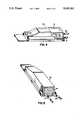
- FIG. 4is a perspective view, partly in phantom, showing the circuit breaker inside a plastic case and FIG. 5 shows the sealed end of the plastic case.
- circuit breaker 20 in accordance with this inventioncomprises a metal base 1 having a raised step 2.
- An elongated compensator bimetal 3, substantially parallel to base 1,is welded to step 2(A).
- Fastened to base 1is a cover 5 which has a step 6(B) at one end.
- An elongated armature bimetal 7, substantially parallel to compensator 3,is welded to step 6.
- Armature 7has a contact 8 which is in contact with contact 4 during normal operation.
- There is an insulated heater wire 9 wrapped around armature 7. End 10, stripped of insulation, of heater wire 9is welded to armature 7.
- End 11stripped of insulation, of heater wire 9 extends outside of base 1 so that when cover 5 is secured to base 1 by, for example, crimping, end 11 is in physical and electrical contact with base 1.
- a sheet insulator 12is disposed between base 1 and cover 5 to insulate them from each other. End 11 extends through opening 19 in insulator 12 to make contact with base 1.
- An advantage to having steps in both cover 5 and base 1is that either compensator 3 or armature 7 may be adjusted to correct opening time or temperature, if necessary, after cover 5 is secured to base 1.
- a purpose of this inventionis to make the opening time and temperature of the circuit breaker substantially insensitive to ambient temperature.
- a predetermined ratio between armature 7 and compensator 3should be met. That is to say, the flexivity times the length squared divided by the thickness of armature 7 should be less than about 21/2 times the flexivity times the length squared divided by the thickness of compensator 3.
- the ambient temperature variationis particularly stringent where the circuit breaker is to be installed under the hood of an automobile, such as the protector for the cooling fan.
- flexivity F, length L and thickness T of armature 7were 14.6, 1.2 inches and 21 mils, respectively.
- Flexivity F, length L and thickness T of compensator 1were 14.0, 0.825 inches and 24 mils, respectively.
- F times L 2 divided by T for armature 7equaled 1001 and, for compensator 3, equaled 397.
- the ratio for the armature to compensatorwas about 21/2 to 1.
- circuit breaker 20For use under the hood of an automobile, the circuit breaker should be sealed. Accordingly, circuit breaker 20 is inserted in a plastic case 13 having an open end which is then sealed with sealing material 14 such as, for example, an epoxy resin which hardens after it fills the open end.
- sealing material 14such as, for example, an epoxy resin which hardens after it fills the open end.
- base 1with a crimp type terminal 15 as an integral part thereof, that is to say, base 1 and terminal 15 are one piece of metal.
- cover 5has crimp type terminal 16 as an integral part thereof.
- Lead-in wires 17 and 18are crimped to terminals 15 and 16, respectively, and extend out of sealing material 14 to provide for external electrical connection.
- circuit breaker 20In operation, if circuit breaker 20 trips open, current will continue to flow through heater wire 9 which will maintain heat on armature 7 and prevent it from closing until the external power source is shut off.
Landscapes
- Breakers (AREA)
- Thermally Actuated Switches (AREA)
Abstract
Description
Claims (5)
Priority Applications (2)
| Application Number | Priority Date | Filing Date | Title |
|---|---|---|---|
| US07/770,002US5103202A (en) | 1991-10-02 | 1991-10-02 | Ambient compensated circuit breaker |
| JP4283428AJPH05234480A (en) | 1991-10-02 | 1992-09-30 | Environmentally Compensated Circuit Breaker |
Applications Claiming Priority (1)
| Application Number | Priority Date | Filing Date | Title |
|---|---|---|---|
| US07/770,002US5103202A (en) | 1991-10-02 | 1991-10-02 | Ambient compensated circuit breaker |
Publications (1)
| Publication Number | Publication Date |
|---|---|
| US5103202Atrue US5103202A (en) | 1992-04-07 |
Family
ID=25087166
Family Applications (1)
| Application Number | Title | Priority Date | Filing Date |
|---|---|---|---|
| US07/770,002Expired - Fee RelatedUS5103202A (en) | 1991-10-02 | 1991-10-02 | Ambient compensated circuit breaker |
Country Status (2)
| Country | Link |
|---|---|
| US (1) | US5103202A (en) |
| JP (1) | JPH05234480A (en) |
Cited By (9)
| Publication number | Priority date | Publication date | Assignee | Title |
|---|---|---|---|---|
| US5936510A (en)* | 1998-05-22 | 1999-08-10 | Portage Electric Products, Inc. | Sealed case hold open thermostat |
| US6498560B2 (en)* | 2001-03-23 | 2002-12-24 | Emerson Electric Co. | Protector assembly and method for electrically insulating a thermally responsive protector from a motor winding of an electric motor |
| US20040021545A1 (en)* | 2001-01-29 | 2004-02-05 | Jurgen Liebe | Thermally tripped circuit breaker |
| US20090102585A1 (en)* | 2006-09-22 | 2009-04-23 | Jeffrey Ramsey Annis | Contactor Assembly With Arc Steering System |
| US20100308954A1 (en)* | 2008-01-28 | 2010-12-09 | Uchiya Thermostat Co., Ltd. | Thermal protector |
| US20110043321A1 (en)* | 2008-04-10 | 2011-02-24 | Uchiya Thermostat Co., Ltd. | External operation thermal protector |
| CN101034643B (en)* | 2006-03-07 | 2011-05-25 | 打矢恒温器株式会社 | Thermostat |
| US10079132B1 (en)* | 2017-03-01 | 2018-09-18 | Siemens Industry, Inc. | Systems, apparatus, and methods for electric circuit breaker tripping |
| US10529514B2 (en)* | 2011-07-05 | 2020-01-07 | Siemens Aktiengesellschaft | Overload release, in particular for a circuit breaker |
Citations (4)
| Publication number | Priority date | Publication date | Assignee | Title |
|---|---|---|---|---|
| US4015229A (en)* | 1975-01-10 | 1977-03-29 | Texas Instruments Incorporated | Thermally responsive switch |
| US4376926A (en)* | 1979-06-27 | 1983-03-15 | Texas Instruments Incorporated | Motor protector calibratable by housing deformation having improved sealing and compactness |
| US4636766A (en)* | 1983-09-19 | 1987-01-13 | Gte Products Corporation | Miniaturized circuit breaker |
| US4924202A (en)* | 1989-02-27 | 1990-05-08 | Gte Products Corporation | Non-cycling electrical circuit breaker |
- 1991
- 1991-10-02USUS07/770,002patent/US5103202A/ennot_activeExpired - Fee Related
- 1992
- 1992-09-30JPJP4283428Apatent/JPH05234480A/ennot_activeWithdrawn
Patent Citations (4)
| Publication number | Priority date | Publication date | Assignee | Title |
|---|---|---|---|---|
| US4015229A (en)* | 1975-01-10 | 1977-03-29 | Texas Instruments Incorporated | Thermally responsive switch |
| US4376926A (en)* | 1979-06-27 | 1983-03-15 | Texas Instruments Incorporated | Motor protector calibratable by housing deformation having improved sealing and compactness |
| US4636766A (en)* | 1983-09-19 | 1987-01-13 | Gte Products Corporation | Miniaturized circuit breaker |
| US4924202A (en)* | 1989-02-27 | 1990-05-08 | Gte Products Corporation | Non-cycling electrical circuit breaker |
Cited By (16)
| Publication number | Priority date | Publication date | Assignee | Title |
|---|---|---|---|---|
| US5936510A (en)* | 1998-05-22 | 1999-08-10 | Portage Electric Products, Inc. | Sealed case hold open thermostat |
| US20040021545A1 (en)* | 2001-01-29 | 2004-02-05 | Jurgen Liebe | Thermally tripped circuit breaker |
| US6498560B2 (en)* | 2001-03-23 | 2002-12-24 | Emerson Electric Co. | Protector assembly and method for electrically insulating a thermally responsive protector from a motor winding of an electric motor |
| CN101034643B (en)* | 2006-03-07 | 2011-05-25 | 打矢恒温器株式会社 | Thermostat |
| US20090102585A1 (en)* | 2006-09-22 | 2009-04-23 | Jeffrey Ramsey Annis | Contactor Assembly With Arc Steering System |
| US7723634B2 (en)* | 2006-09-22 | 2010-05-25 | Rockwell Automation Technologies, Inc. | Contactor assembly with arc steering system |
| US8736416B2 (en)* | 2008-01-28 | 2014-05-27 | Uchiya Thermostat Co., Ltd. | Thermal protector |
| US20130076480A1 (en)* | 2008-01-28 | 2013-03-28 | Uchiya Thermostat Co., Ltd. | Thermal protector |
| US8421580B2 (en)* | 2008-01-28 | 2013-04-16 | Uchiya Thermostat Co., Ltd. | Thermal protector |
| US20100308954A1 (en)* | 2008-01-28 | 2010-12-09 | Uchiya Thermostat Co., Ltd. | Thermal protector |
| US20110043321A1 (en)* | 2008-04-10 | 2011-02-24 | Uchiya Thermostat Co., Ltd. | External operation thermal protector |
| US20130015944A1 (en)* | 2008-04-10 | 2013-01-17 | Uchiya Thermostat Co., Ltd. | External operation thermal protector |
| US8519816B2 (en)* | 2008-04-10 | 2013-08-27 | Uchiya Thermostat Co., Ltd. | External operation thermal protector |
| US8749341B2 (en)* | 2008-04-10 | 2014-06-10 | Uchiya Thermostat Co., Ltd. | External operation thermal protector |
| US10529514B2 (en)* | 2011-07-05 | 2020-01-07 | Siemens Aktiengesellschaft | Overload release, in particular for a circuit breaker |
| US10079132B1 (en)* | 2017-03-01 | 2018-09-18 | Siemens Industry, Inc. | Systems, apparatus, and methods for electric circuit breaker tripping |
Also Published As
| Publication number | Publication date |
|---|---|
| JPH05234480A (en) | 1993-09-10 |
Similar Documents
| Publication | Publication Date | Title |
|---|---|---|
| US3430177A (en) | Miniature thermostatic switch | |
| US5936510A (en) | Sealed case hold open thermostat | |
| US4136323A (en) | Miniature motor protector | |
| US4015229A (en) | Thermally responsive switch | |
| US5103202A (en) | Ambient compensated circuit breaker | |
| US4636766A (en) | Miniaturized circuit breaker | |
| KR101495023B1 (en) | Protective device, in particular for the control electronics of a motor vehicle component | |
| JP2799204B2 (en) | A device that combines a motor protection device and a starter | |
| US4458231A (en) | Protector apparatus for dynamoelectric machines | |
| US5014035A (en) | Bimetallic circuit breaker with insulated terminal assembly | |
| US3489976A (en) | Self-protected time delay relay | |
| US3453577A (en) | Compact thermostatic snap switch with heater for protection of motor windings and the like | |
| US2791660A (en) | Electrical fuse | |
| US3609620A (en) | Thermostatic switch | |
| US4521760A (en) | Miniaturized circuit breaker | |
| CA1133548A (en) | Thermostatic electrical switch | |
| US4114127A (en) | Current interrupting apparatus | |
| US4334209A (en) | Glass enclosed three lead circuit breaker | |
| US3833873A (en) | Thermal protector | |
| EP3910660B1 (en) | Thermal cutoff | |
| US4486732A (en) | Ambient compensated motor protector | |
| JPS645729B2 (en) | ||
| US6276969B1 (en) | Terminal connector for sealed electromotive compressors | |
| US3656079A (en) | Thermostatic switch | |
| MY133443A (en) | Motor protector apparatus |
Legal Events
| Date | Code | Title | Description |
|---|---|---|---|
| AS | Assignment | Owner name:GTE PRODUCTS CORPORATION, A CORP. OF DE Free format text:ASSIGNMENT OF ASSIGNORS INTEREST.;ASSIGNORS:LENNON, JOHN D.;CARBONE, DOUGLAS C.;REEL/FRAME:005860/0789;SIGNING DATES FROM 19910923 TO 19910925 | |
| AS | Assignment | Owner name:GTE CONTROL DEVICES INCORPORATED, MAINE Free format text:ASSIGNS THE ENTIRE INTEREST, SUBJECT TO CONDITIONS RECITED.;ASSIGNOR:GTE PRODUCTS CORPORATION A CORP. OF DELAWARE;REEL/FRAME:006192/0310 Effective date:19920529 | |
| AS | Assignment | Owner name:CONTROL DEVICES, INC., MAINE Free format text:ASSIGNMENT OF ASSIGNORS INTEREST;ASSIGNOR:GTE CONTROL DEVICES INCORPORATED;REEL/FRAME:007077/0677 Effective date:19940726 Owner name:MASSMUTUAL PARTICIPATION INVESTORS A MASSACHUSETTS Free format text:SECURITY INTEREST;ASSIGNOR:CONTROL DEVICES, INC.;REEL/FRAME:007072/0269 Effective date:19940729 Owner name:MASSACHUSETTS MUTUAL LIFE INSURANCE COMPANY A MAS Free format text:SECURITY INTEREST;ASSIGNOR:CONTROL DEVICES, INC.;REEL/FRAME:007072/0269 Effective date:19940729 Owner name:MASSMUTUAL CORPORATE INVESTORS A MASSACHUSETTS BUS Free format text:SECURITY INTEREST;ASSIGNOR:CONTROL DEVICES, INC.;REEL/FRAME:007072/0269 Effective date:19940729 | |
| REMI | Maintenance fee reminder mailed | ||
| LAPS | Lapse for failure to pay maintenance fees | ||
| FP | Lapsed due to failure to pay maintenance fee | Effective date:19960410 | |
| AS | Assignment | Owner name:CONTROL DEVICES, INC., MAINE Free format text:RELEASE OF SECURITY & PLEDGE AGREEMENT;ASSIGNORS:MASSACHUSETTS MUTUAL LIFE INSURANCE CO.;MASSMUTUAL CORPORATE INVESTORS;MASSMUTUAL PARTICIPATION INVESTORS;REEL/FRAME:008194/0795 Effective date:19961008 | |
| STCH | Information on status: patent discontinuation | Free format text:PATENT EXPIRED DUE TO NONPAYMENT OF MAINTENANCE FEES UNDER 37 CFR 1.362 |