US5103068A - Connector twist tie - Google Patents
Connector twist tieDownload PDFInfo
- Publication number
- US5103068A US5103068AUS07/655,988US65598891AUS5103068AUS 5103068 AUS5103068 AUS 5103068AUS 65598891 AUS65598891 AUS 65598891AUS 5103068 AUS5103068 AUS 5103068A
- Authority
- US
- United States
- Prior art keywords
- conductor
- tying device
- connector
- electrical conductors
- receiving recesses
- Prior art date
- Legal status (The legal status is an assumption and is not a legal conclusion. Google has not performed a legal analysis and makes no representation as to the accuracy of the status listed.)
- Expired - Lifetime
Links
- 239000004020conductorSubstances0.000claimsabstractdescription35
- 238000002788crimpingMethods0.000claimsabstractdescription14
- 238000000034methodMethods0.000claimsabstractdescription14
- 230000006835compressionEffects0.000claimsdescription12
- 238000007906compressionMethods0.000claimsdescription12
- RYGMFSIKBFXOCR-UHFFFAOYSA-NCopperChemical compound[Cu]RYGMFSIKBFXOCR-UHFFFAOYSA-N0.000claimsdescription9
- 229910052802copperInorganic materials0.000claimsdescription8
- 239000010949copperSubstances0.000claimsdescription8
- 239000000463materialSubstances0.000claimsdescription5
- 238000003825pressingMethods0.000claims1
- XAGFODPZIPBFFR-UHFFFAOYSA-NaluminiumChemical compound[Al]XAGFODPZIPBFFR-UHFFFAOYSA-N0.000description2
- 229910052782aluminiumInorganic materials0.000description2
- 238000004519manufacturing processMethods0.000description2
- 230000007812deficiencyEffects0.000description1
- 238000009826distributionMethods0.000description1
- 230000000694effectsEffects0.000description1
- 238000001125extrusionMethods0.000description1
Images

Classifications
- H—ELECTRICITY
- H01—ELECTRIC ELEMENTS
- H01R—ELECTRICALLY-CONDUCTIVE CONNECTIONS; STRUCTURAL ASSOCIATIONS OF A PLURALITY OF MUTUALLY-INSULATED ELECTRICAL CONNECTING ELEMENTS; COUPLING DEVICES; CURRENT COLLECTORS
- H01R4/00—Electrically-conductive connections between two or more conductive members in direct contact, i.e. touching one another; Means for effecting or maintaining such contact; Electrically-conductive connections having two or more spaced connecting locations for conductors and using contact members penetrating insulation
- H01R4/10—Electrically-conductive connections between two or more conductive members in direct contact, i.e. touching one another; Means for effecting or maintaining such contact; Electrically-conductive connections having two or more spaced connecting locations for conductors and using contact members penetrating insulation effected solely by twisting, wrapping, bending, crimping, or other permanent deformation
- H01R4/18—Electrically-conductive connections between two or more conductive members in direct contact, i.e. touching one another; Means for effecting or maintaining such contact; Electrically-conductive connections having two or more spaced connecting locations for conductors and using contact members penetrating insulation effected solely by twisting, wrapping, bending, crimping, or other permanent deformation by crimping
- H01R4/183—Electrically-conductive connections between two or more conductive members in direct contact, i.e. touching one another; Means for effecting or maintaining such contact; Electrically-conductive connections having two or more spaced connecting locations for conductors and using contact members penetrating insulation effected solely by twisting, wrapping, bending, crimping, or other permanent deformation by crimping for cylindrical elongated bodies, e.g. cables having circular cross-section
- H01R4/186—Electrically-conductive connections between two or more conductive members in direct contact, i.e. touching one another; Means for effecting or maintaining such contact; Electrically-conductive connections having two or more spaced connecting locations for conductors and using contact members penetrating insulation effected solely by twisting, wrapping, bending, crimping, or other permanent deformation by crimping for cylindrical elongated bodies, e.g. cables having circular cross-section using a body comprising a plurality of cable-accommodating recesses or bores
- Y—GENERAL TAGGING OF NEW TECHNOLOGICAL DEVELOPMENTS; GENERAL TAGGING OF CROSS-SECTIONAL TECHNOLOGIES SPANNING OVER SEVERAL SECTIONS OF THE IPC; TECHNICAL SUBJECTS COVERED BY FORMER USPC CROSS-REFERENCE ART COLLECTIONS [XRACs] AND DIGESTS
- Y10—TECHNICAL SUBJECTS COVERED BY FORMER USPC
- Y10T—TECHNICAL SUBJECTS COVERED BY FORMER US CLASSIFICATION
- Y10T29/00—Metal working
- Y10T29/49—Method of mechanical manufacture
- Y10T29/49002—Electrical device making
- Y10T29/49117—Conductor or circuit manufacturing
- Y10T29/49174—Assembling terminal to elongated conductor
- Y10T29/49181—Assembling terminal to elongated conductor by deforming
- Y10T29/49185—Assembling terminal to elongated conductor by deforming of terminal
- Y—GENERAL TAGGING OF NEW TECHNOLOGICAL DEVELOPMENTS; GENERAL TAGGING OF CROSS-SECTIONAL TECHNOLOGIES SPANNING OVER SEVERAL SECTIONS OF THE IPC; TECHNICAL SUBJECTS COVERED BY FORMER USPC CROSS-REFERENCE ART COLLECTIONS [XRACs] AND DIGESTS
- Y10—TECHNICAL SUBJECTS COVERED BY FORMER USPC
- Y10T—TECHNICAL SUBJECTS COVERED BY FORMER US CLASSIFICATION
- Y10T403/00—Joints and connections
- Y10T403/71—Rod side to plate or side
- Y10T403/7129—Laterally spaced rods
- Y10T403/7141—Plural channels in connector
Definitions
- This inventionbroadly pertains to electrical connectors for wire or cable conductors. More specifically, the invention relates to a compressor-type electrical connector for connecting a plurality of connectors together in an electrical power distribution system. The invention finds particular application in establishing a tap connection to provide a branch current from a continuous run main power cable.
- An electrical connector of the aforesaid typeis typically adapted to receive a tap connector, to engage a continuous run conductor, and to be compressed by means of a crimping tool to achieve the desired connection.
- the Nilsson et al patentdescribes a parallel tap connector adapted to effect inter-engagement between a main line and one or more branch lines to maintain the lines in electrical contact at the point of engagement without external holding devices.
- the connectorcontains various channels 11,12 adapted to receive various cables or conductors therein.
- a pair of springs 17, associated with channel 11,is attached to the connector and bent in such manner to coact with the cable or conductor to prevent it from becoming dislodged from the connector.
- the patent to Whitleyis directed to a connector with a temporary holding device placed into the slot or other opening in the connector device.
- This temporary cable holding devicecomprises a spring clip 16 generally in a U-shaped configuration adapted to conform to various ridges provided in the interior channels of the connector.
- the patent to Lynch, Jr. et alalso describes a connector with a temporary cable holding device.
- This temporary holding deviceconsists of an end plate 20 which is adapted to be provided at one or both ends of the connector.
- Kearnysuch as shown in U.S. Pat. No. 2,707,775, and consists of an H-frame copper compression connector provided with one or more impacted tabs provided adjacent to the channels for receiving the conductors. The purpose of these tabs is to hold the connector in place before and during the crimping operation.
- aluminum compression connectors having these tabscan be manufactured in a single extrusion process, copper compression connectors must use a two-step process for including these tabs in the connector structure.
- the present inventionovercomes the deficiencies of the prior art by producing a connector which is less costly to manufacture than the prior art connectors, due in part to its ease of manufacture.
- a grooveis provided in one or more surfaces of the connector and an elongated tying device is press-fitted into the groove. This tying device extends for a sufficient length on either end of the grooved surface so as to be tied or twisted around both ends of a conductor or conductors preparatory to the crimping process.
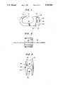
- FIG. 1is an end elevational view of a first embodiment of the present invention
- FIG. 2is a bottom elevational view of the first embodiment of the present invention
- FIG. 3is an end elevational view of a second embodiment of the present invention.
- FIG. 4is a side elevational view of the second embodiment of the present invention.
- FIG. 5is a perspective view of the first embodiment of the present invention illustrating the tying arrangement.
- FIGS. 1 and 2illustrate a first embodiment of the present invention employing a FIG. 6-type compression connector 10.
- This connectorcontains slots or channels 12,14 and 16 to accommodate one or more single strand, multi-strand conductors or cables. Surfaces 18, 20 and 22 are provided in the interior of the respective slots or channels to accommodate the various conductors or cables. Although this connector is provided with differently-sized slots or channels 12, 14 and 16, this need not be the case, and these slots or channels can be of equal dimension.
- the bottom surface 24 of this connectorhas been extruded with a groove 28 extending for the entire width of the bottom surface 24.
- a copper twist tie 26is secured into the groove 28 of the connector 10 and is of sufficient length to be twisted around the conductor or conductors, thus providing a holding and tying device for the conductors within the connector.
- This particular connectorcan be manufactured from tin-plated copper and, therefore, the entire connector can be extruded in a single operation.
- the Kearny connector containing one or more securing tabscan only be manufactured from a copper-based material using an impacted tab which would constitute a two-step process.
- the connector illustrated in FIGS. 1 and 2can be used with various ranges or sizes of conductors or cables.
- FIGS. 3 and 4A second embodiment of the present invention is illustrated with respect to FIGS. 3 and 4. These figures describe a H-frame connector 30 provided with two slots or channels 32,34, each of which contains an inner surface 36 or 38 to allow various conductors or cables to be inserted into the connector 30.
- a side surface 40is provided having an extruded groove 42 extending for the entire width of the surface 40.
- a holding and tying devicesuch as an elongated piece of wax covered twine 42, is secured into the groove 44 and extends for a sufficient length to be tied around the various conductors.
- This particular conductorcan be manufactured from tin-plated copper, aluminum or similar materials. Additionally, the twine 42 could be manufactured from a tin-plated material.
- FIG. 5illustrates the application of the present invention to the embodiment illustrated with respect to FIGS. 1 and 2, after the crimping process has been completed.
- multi-strand conductors 46, 48 and 50are inserted into their respective slots or channels 12, 16 and 14.
- Each end of the copper wireis twisted or tied around the entire group of conductors or cables to secure the cables prior to the crimping process.
- the connectoris then inserted into the proper mechanical, pneumatic or hydraulic crimping tool, and then the crimping process is effectuated. Once this process is completed, the copper twist tie can remain in place or be snipped off.
Landscapes
- Connections Effected By Soldering, Adhesion, Or Permanent Deformation (AREA)
- Manufacturing Of Electrical Connectors (AREA)
- Multi-Conductor Connections (AREA)
- Coupling Device And Connection With Printed Circuit (AREA)
Abstract
Description
Claims (8)
Priority Applications (6)
| Application Number | Priority Date | Filing Date | Title |
|---|---|---|---|
| US07/655,988US5103068A (en) | 1991-02-15 | 1991-02-15 | Connector twist tie |
| EP19920101982EP0499146A3 (en) | 1991-02-15 | 1992-02-06 | Connector twist tie |
| CA002060756ACA2060756C (en) | 1991-02-15 | 1992-02-06 | Connector twist tie |
| AU10787/92AAU641845B2 (en) | 1991-02-15 | 1992-02-06 | Connector twist tie |
| JP04028218AJP3138046B2 (en) | 1991-02-15 | 1992-02-14 | Compression type electrical connector |
| KR1019920002177AKR920017298A (en) | 1991-02-15 | 1992-02-14 | Compression electrical connector |
Applications Claiming Priority (1)
| Application Number | Priority Date | Filing Date | Title |
|---|---|---|---|
| US07/655,988US5103068A (en) | 1991-02-15 | 1991-02-15 | Connector twist tie |
Publications (1)
| Publication Number | Publication Date |
|---|---|
| US5103068Atrue US5103068A (en) | 1992-04-07 |
Family
ID=24631196
Family Applications (1)
| Application Number | Title | Priority Date | Filing Date |
|---|---|---|---|
| US07/655,988Expired - LifetimeUS5103068A (en) | 1991-02-15 | 1991-02-15 | Connector twist tie |
Country Status (6)
| Country | Link |
|---|---|
| US (1) | US5103068A (en) |
| EP (1) | EP0499146A3 (en) |
| JP (1) | JP3138046B2 (en) |
| KR (1) | KR920017298A (en) |
| AU (1) | AU641845B2 (en) |
| CA (1) | CA2060756C (en) |
Cited By (35)
| Publication number | Priority date | Publication date | Assignee | Title |
|---|---|---|---|---|
| US5162615A (en)* | 1991-02-15 | 1992-11-10 | Burndy Corporation | Full closure H-shaped connector |
| US5200576A (en)* | 1991-02-15 | 1993-04-06 | Burndy Corporation | Multi-point contact compression connector |
| US5635676A (en)* | 1992-12-09 | 1997-06-03 | Thomas & Betts Corporation | Compression connectors |
| US6303861B1 (en)* | 1999-10-21 | 2001-10-16 | Fci Usa, Inc. | Connector for connecting a conductor to a structural member |
| US6452103B1 (en)* | 1997-08-19 | 2002-09-17 | Thomas & Betts International, Inc. | Compression connector |
| US6486403B1 (en)* | 2001-07-10 | 2002-11-26 | Fci Usa, Inc. | Electrical compression connector |
| US6525270B1 (en)* | 2000-10-13 | 2003-02-25 | Fci Usa, Inc. | Compression connector |
| US6538204B2 (en)* | 2001-07-10 | 2003-03-25 | Fci Usa, Inc. | Electrical compression connector |
| US6552271B2 (en)* | 2001-07-10 | 2003-04-22 | Fci Usa, Inc. | Electrical compression connector |
| US20040058571A1 (en)* | 2001-01-22 | 2004-03-25 | Thomas & Betts International Inc. | Ground bus bar connector |
| US20040074666A1 (en)* | 2002-09-26 | 2004-04-22 | O'grady Bernard J. | H-tap compression connector |
| US6747211B2 (en)* | 2001-07-10 | 2004-06-08 | Fci Usa, Inc. | Electrical compression connector |
| US6846989B2 (en) | 2002-09-26 | 2005-01-25 | Panduit Corp. | Multi-tap compression connector |
| US20050071957A1 (en)* | 2003-10-07 | 2005-04-07 | Dembicks Tyler J. | Crimp |
| US20050098341A1 (en)* | 2003-09-24 | 2005-05-12 | Kossak Robert W. | Multi-port compression connector |
| US20050235463A1 (en)* | 2003-10-07 | 2005-10-27 | North State Tackle | Crimp |
| US20060019540A1 (en)* | 2004-07-26 | 2006-01-26 | Fci Americas Technology, Inc. | Performance indicating electrical connector |
| US20060040546A1 (en)* | 2004-07-26 | 2006-02-23 | Fci Americas Technology, Inc. | Performance indicating electrical connector |
| US20060201695A1 (en)* | 2003-09-24 | 2006-09-14 | Kossak Robert W | Multi-port compression connector |
| US7511224B1 (en) | 2008-03-11 | 2009-03-31 | Panduit Corp. | Compression connector with tap port configured to engage multiple sized tap wires in a single tap port |
| US20090260875A1 (en)* | 2008-04-16 | 2009-10-22 | Panduit Corp. | Multi-Port Compression Connector with Single Tap Wire Access Port |
| US20100151735A1 (en)* | 2008-12-17 | 2010-06-17 | Fci Americas Technology, Inc. | Data collecting connection |
| US20110306232A1 (en)* | 2008-10-31 | 2011-12-15 | Anthony Freakes | Insulation Displacement Connector |
| US20150152942A1 (en)* | 2013-12-02 | 2015-06-04 | Schlage Lock Company Llc | Multi-pass crimp collar for a looped cable |
| US20150280363A1 (en)* | 2011-11-08 | 2015-10-01 | Ortronics, Inc. | Cable Assemblies and Associated Systems and Methods |
| US9680293B2 (en) | 2014-06-02 | 2017-06-13 | Kurt Vilhelmsen | Surface mounted multiple cable or wire organizer |
| US9697724B2 (en) | 2010-09-22 | 2017-07-04 | Hubbell Incorporated | Transmission line measuring device and method for connectivity and monitoring |
| US10122094B1 (en)* | 2017-08-15 | 2018-11-06 | Eaton Intelligent Power Limited | Wire terminating post and electrical device including same |
| US10228001B2 (en) | 2010-09-22 | 2019-03-12 | Hubbell Incorporated | Transmission line measuring device and method for connectivity |
| US10547124B2 (en) | 2017-08-20 | 2020-01-28 | Hubbell Incorporated | Compression connector |
| US20200044368A1 (en)* | 2018-08-06 | 2020-02-06 | Panduit Corp. | Grounding Connector |
| USD908098S1 (en)* | 2019-10-11 | 2021-01-19 | Electric Solutions Co., Ltd. | Branch connection sleeve for power line and ground wire |
| US10965043B2 (en) | 2017-10-12 | 2021-03-30 | Hubbell Incorporated | Set screw connector |
| US11264736B2 (en) | 2018-08-20 | 2022-03-01 | Hubbell Incorporated | Insulation piercing connector |
| US11605906B2 (en) | 2019-01-18 | 2023-03-14 | Hubbell Incorporated | Compression connectors with insulating cover |
Families Citing this family (2)
| Publication number | Priority date | Publication date | Assignee | Title |
|---|---|---|---|---|
| JP5592512B2 (en)* | 2013-01-25 | 2014-09-17 | 中国電力株式会社 | Compression sleeve for wire branch |
| IT202000012400A1 (en)* | 2020-05-26 | 2021-11-26 | Ferplast Spa | HOOK ELEMENT FOR THE ASSEMBLY OF CAGES USED FOR THE CONTAINMENT OF PETS |
Citations (18)
| Publication number | Priority date | Publication date | Assignee | Title |
|---|---|---|---|---|
| US2707775A (en)* | 1951-01-22 | 1955-05-03 | Kearney James R Corp | Electrical connectors |
| US2938069A (en)* | 1957-03-07 | 1960-05-24 | Jasper Blackburn Corp | Compression type electrical connectors |
| US2956108A (en)* | 1958-03-26 | 1960-10-11 | Penn Union Electric Corp | Connector |
| US2964585A (en)* | 1958-06-05 | 1960-12-13 | Anderson Electric Corp | Parallel tap connector |
| US3032603A (en)* | 1961-02-27 | 1962-05-01 | Effco Inc | Connector with temporary cable holding means |
| US3053930A (en)* | 1960-02-04 | 1962-09-11 | Burndy Corp | Electrical connector |
| US3183025A (en)* | 1963-05-16 | 1965-05-11 | Thomas & Betts Corp | Connector with temporary cable holding means |
| US3235654A (en)* | 1964-03-19 | 1966-02-15 | Thomas & Betts Corp | Compression tap |
| US3236938A (en)* | 1962-03-26 | 1966-02-22 | Jasper Blackburn Corp | Compressible electrical connector |
| US3330903A (en)* | 1965-06-18 | 1967-07-11 | Kearney National Inc | Compression connector with removable tabs for a range of conductor sizes |
| US3340352A (en)* | 1965-09-11 | 1967-09-05 | Amp Inc | Sectional tap connector |
| US3354517A (en)* | 1966-05-17 | 1967-11-28 | Thomas And Betts Co Inc | Compressible connector |
| US3408455A (en)* | 1967-05-25 | 1968-10-29 | Burndy Corp | Electrical connector with conductor retainers |
| US3746777A (en)* | 1972-08-30 | 1973-07-17 | Anderson Electric Corp | Compression connector for electrical conductors with tabs in series |
| US3781459A (en)* | 1972-07-20 | 1973-12-25 | Anderson Electric Corp | Compression connector for electrical conductors |
| US4350843A (en)* | 1978-08-31 | 1982-09-21 | Square D Company | Method and system for crimping a metal connector |
| US4940856A (en)* | 1989-06-26 | 1990-07-10 | Burndy Corporation | Electrical connector |
| US4950838A (en)* | 1989-06-26 | 1990-08-21 | Burndy Corporation | Electrical connector |
Family Cites Families (2)
| Publication number | Priority date | Publication date | Assignee | Title |
|---|---|---|---|---|
| US3322888A (en)* | 1966-05-12 | 1967-05-30 | Kearney National Inc | Compression connector |
| FR2053781A5 (en)* | 1969-07-17 | 1971-04-16 | Zeiss Jena Veb Carl |
- 1991
- 1991-02-15USUS07/655,988patent/US5103068A/ennot_activeExpired - Lifetime
- 1992
- 1992-02-06EPEP19920101982patent/EP0499146A3/ennot_activeCeased
- 1992-02-06CACA002060756Apatent/CA2060756C/ennot_activeExpired - Fee Related
- 1992-02-06AUAU10787/92Apatent/AU641845B2/ennot_activeCeased
- 1992-02-14KRKR1019920002177Apatent/KR920017298A/ennot_activeWithdrawn
- 1992-02-14JPJP04028218Apatent/JP3138046B2/ennot_activeExpired - Fee Related
Patent Citations (18)
| Publication number | Priority date | Publication date | Assignee | Title |
|---|---|---|---|---|
| US2707775A (en)* | 1951-01-22 | 1955-05-03 | Kearney James R Corp | Electrical connectors |
| US2938069A (en)* | 1957-03-07 | 1960-05-24 | Jasper Blackburn Corp | Compression type electrical connectors |
| US2956108A (en)* | 1958-03-26 | 1960-10-11 | Penn Union Electric Corp | Connector |
| US2964585A (en)* | 1958-06-05 | 1960-12-13 | Anderson Electric Corp | Parallel tap connector |
| US3053930A (en)* | 1960-02-04 | 1962-09-11 | Burndy Corp | Electrical connector |
| US3032603A (en)* | 1961-02-27 | 1962-05-01 | Effco Inc | Connector with temporary cable holding means |
| US3236938A (en)* | 1962-03-26 | 1966-02-22 | Jasper Blackburn Corp | Compressible electrical connector |
| US3183025A (en)* | 1963-05-16 | 1965-05-11 | Thomas & Betts Corp | Connector with temporary cable holding means |
| US3235654A (en)* | 1964-03-19 | 1966-02-15 | Thomas & Betts Corp | Compression tap |
| US3330903A (en)* | 1965-06-18 | 1967-07-11 | Kearney National Inc | Compression connector with removable tabs for a range of conductor sizes |
| US3340352A (en)* | 1965-09-11 | 1967-09-05 | Amp Inc | Sectional tap connector |
| US3354517A (en)* | 1966-05-17 | 1967-11-28 | Thomas And Betts Co Inc | Compressible connector |
| US3408455A (en)* | 1967-05-25 | 1968-10-29 | Burndy Corp | Electrical connector with conductor retainers |
| US3781459A (en)* | 1972-07-20 | 1973-12-25 | Anderson Electric Corp | Compression connector for electrical conductors |
| US3746777A (en)* | 1972-08-30 | 1973-07-17 | Anderson Electric Corp | Compression connector for electrical conductors with tabs in series |
| US4350843A (en)* | 1978-08-31 | 1982-09-21 | Square D Company | Method and system for crimping a metal connector |
| US4940856A (en)* | 1989-06-26 | 1990-07-10 | Burndy Corporation | Electrical connector |
| US4950838A (en)* | 1989-06-26 | 1990-08-21 | Burndy Corporation | Electrical connector |
Cited By (62)
| Publication number | Priority date | Publication date | Assignee | Title |
|---|---|---|---|---|
| US5162615A (en)* | 1991-02-15 | 1992-11-10 | Burndy Corporation | Full closure H-shaped connector |
| US5200576A (en)* | 1991-02-15 | 1993-04-06 | Burndy Corporation | Multi-point contact compression connector |
| US5635676A (en)* | 1992-12-09 | 1997-06-03 | Thomas & Betts Corporation | Compression connectors |
| US6452103B1 (en)* | 1997-08-19 | 2002-09-17 | Thomas & Betts International, Inc. | Compression connector |
| US6303861B1 (en)* | 1999-10-21 | 2001-10-16 | Fci Usa, Inc. | Connector for connecting a conductor to a structural member |
| US6525270B1 (en)* | 2000-10-13 | 2003-02-25 | Fci Usa, Inc. | Compression connector |
| US20040058571A1 (en)* | 2001-01-22 | 2004-03-25 | Thomas & Betts International Inc. | Ground bus bar connector |
| US20060021783A1 (en)* | 2001-01-22 | 2006-02-02 | Thomas & Betts International, Inc. | Ground bus bar connector |
| US7173187B2 (en) | 2001-01-22 | 2007-02-06 | Thomas & Betts International, Inc. | Ground bus bar connector |
| US6989491B2 (en)* | 2001-01-22 | 2006-01-24 | Thomas & Betts International, Inc. | Ground bus bar connector |
| US6486403B1 (en)* | 2001-07-10 | 2002-11-26 | Fci Usa, Inc. | Electrical compression connector |
| US6538204B2 (en)* | 2001-07-10 | 2003-03-25 | Fci Usa, Inc. | Electrical compression connector |
| US6552271B2 (en)* | 2001-07-10 | 2003-04-22 | Fci Usa, Inc. | Electrical compression connector |
| US6747211B2 (en)* | 2001-07-10 | 2004-06-08 | Fci Usa, Inc. | Electrical compression connector |
| US20040074666A1 (en)* | 2002-09-26 | 2004-04-22 | O'grady Bernard J. | H-tap compression connector |
| KR100997928B1 (en) | 2002-09-26 | 2010-12-02 | 팬듀트 코포레이션 | Multi-tap Compression Connector |
| CN100369325C (en)* | 2002-09-26 | 2008-02-13 | 潘都依特有限公司 | Multi-tap compression connector |
| US20050139374A1 (en)* | 2002-09-26 | 2005-06-30 | Sokol Robert L. | Multi-tap compression connector |
| US20050039942A1 (en)* | 2002-09-26 | 2005-02-24 | O'grady Bernard J. | H-tap compression connector |
| US6846989B2 (en) | 2002-09-26 | 2005-01-25 | Panduit Corp. | Multi-tap compression connector |
| US6818830B2 (en)* | 2002-09-26 | 2004-11-16 | Panduit Corp. | H-tap compression connector |
| US7026552B2 (en)* | 2002-09-26 | 2006-04-11 | Panduit Corp. | Multi-tap compression connector |
| US7121001B2 (en) | 2002-09-26 | 2006-10-17 | Panduit Corp. | H-tap compression connector |
| US7183489B2 (en)* | 2003-09-24 | 2007-02-27 | Panduit Corp. | Multi-port compression connector |
| US7053307B2 (en) | 2003-09-24 | 2006-05-30 | Panduit Corp. | Multi-port compression connector |
| US20060201695A1 (en)* | 2003-09-24 | 2006-09-14 | Kossak Robert W | Multi-port compression connector |
| US20050098341A1 (en)* | 2003-09-24 | 2005-05-12 | Kossak Robert W. | Multi-port compression connector |
| US20050071957A1 (en)* | 2003-10-07 | 2005-04-07 | Dembicks Tyler J. | Crimp |
| US7032345B2 (en)* | 2003-10-07 | 2006-04-25 | North State Tackle | Crimp |
| US20050235463A1 (en)* | 2003-10-07 | 2005-10-27 | North State Tackle | Crimp |
| US20060040546A1 (en)* | 2004-07-26 | 2006-02-23 | Fci Americas Technology, Inc. | Performance indicating electrical connector |
| US20060019540A1 (en)* | 2004-07-26 | 2006-01-26 | Fci Americas Technology, Inc. | Performance indicating electrical connector |
| US7306489B2 (en) | 2004-07-26 | 2007-12-11 | Fci Americas Technology, Inc. | Performance indicating electrical connector |
| WO2006020193A1 (en)* | 2004-07-26 | 2006-02-23 | Fci Americas Technology, Inc. | Performance indicating electrical connector |
| CN101533967B (en)* | 2008-03-11 | 2013-04-03 | 泛达公司 | Compression connector with tap port configured to engage multiple sized tap wires in a single tap port |
| US7511224B1 (en) | 2008-03-11 | 2009-03-31 | Panduit Corp. | Compression connector with tap port configured to engage multiple sized tap wires in a single tap port |
| CN101533967A (en)* | 2008-03-11 | 2009-09-16 | 泛达公司 | Compression connector with tap port configured to engage multiple sized tap wires in a single tap port |
| US7655863B2 (en) | 2008-04-16 | 2010-02-02 | Panduit Corp. | Multi-port compression connector with single tap wire access port |
| US20090260875A1 (en)* | 2008-04-16 | 2009-10-22 | Panduit Corp. | Multi-Port Compression Connector with Single Tap Wire Access Port |
| US8337263B2 (en)* | 2008-10-31 | 2012-12-25 | Anthony Freakes | Insulation displacement connector |
| US20110306232A1 (en)* | 2008-10-31 | 2011-12-15 | Anthony Freakes | Insulation Displacement Connector |
| US8002592B2 (en) | 2008-12-17 | 2011-08-23 | Hubbell Incorporated | Data collecting connection |
| US8475219B2 (en) | 2008-12-17 | 2013-07-02 | Hubbell Incorporated | Data collecting connection |
| US20100151735A1 (en)* | 2008-12-17 | 2010-06-17 | Fci Americas Technology, Inc. | Data collecting connection |
| US9928730B2 (en) | 2010-09-22 | 2018-03-27 | Hubbell Incorporated | Transmission line measuring device and method for connectivity and monitoring |
| US10228001B2 (en) | 2010-09-22 | 2019-03-12 | Hubbell Incorporated | Transmission line measuring device and method for connectivity |
| US9697724B2 (en) | 2010-09-22 | 2017-07-04 | Hubbell Incorporated | Transmission line measuring device and method for connectivity and monitoring |
| US9767685B2 (en) | 2010-09-22 | 2017-09-19 | Hubbell Incorporated | Transmission line measuring device and method for connectivity and monitoring |
| US20150280363A1 (en)* | 2011-11-08 | 2015-10-01 | Ortronics, Inc. | Cable Assemblies and Associated Systems and Methods |
| US9601880B2 (en)* | 2011-11-08 | 2017-03-21 | Ortronics, Inc. | Cable assemblies and associated systems and methods |
| US10221523B2 (en)* | 2013-12-02 | 2019-03-05 | Schlage Lock Company Llc | Multi-pass crimp collar for a looped cable |
| US9828724B2 (en)* | 2013-12-02 | 2017-11-28 | Schlage Lock Company Llc | Multi-pass crimp collar for a looped cable |
| US20150152942A1 (en)* | 2013-12-02 | 2015-06-04 | Schlage Lock Company Llc | Multi-pass crimp collar for a looped cable |
| US9680293B2 (en) | 2014-06-02 | 2017-06-13 | Kurt Vilhelmsen | Surface mounted multiple cable or wire organizer |
| US10122094B1 (en)* | 2017-08-15 | 2018-11-06 | Eaton Intelligent Power Limited | Wire terminating post and electrical device including same |
| US10547124B2 (en) | 2017-08-20 | 2020-01-28 | Hubbell Incorporated | Compression connector |
| US10965043B2 (en) | 2017-10-12 | 2021-03-30 | Hubbell Incorporated | Set screw connector |
| US20200044368A1 (en)* | 2018-08-06 | 2020-02-06 | Panduit Corp. | Grounding Connector |
| US10985474B2 (en)* | 2018-08-06 | 2021-04-20 | Panduit Corp. | Grounding connector with lock joint |
| US11264736B2 (en) | 2018-08-20 | 2022-03-01 | Hubbell Incorporated | Insulation piercing connector |
| US11605906B2 (en) | 2019-01-18 | 2023-03-14 | Hubbell Incorporated | Compression connectors with insulating cover |
| USD908098S1 (en)* | 2019-10-11 | 2021-01-19 | Electric Solutions Co., Ltd. | Branch connection sleeve for power line and ground wire |
Also Published As
| Publication number | Publication date |
|---|---|
| KR920017298A (en) | 1992-09-26 |
| JP3138046B2 (en) | 2001-02-26 |
| CA2060756A1 (en) | 1992-08-16 |
| EP0499146A2 (en) | 1992-08-19 |
| CA2060756C (en) | 2001-12-11 |
| EP0499146A3 (en) | 1993-08-18 |
| AU641845B2 (en) | 1993-09-30 |
| JPH0562720A (en) | 1993-03-12 |
| AU1078792A (en) | 1992-08-20 |
Similar Documents
| Publication | Publication Date | Title |
|---|---|---|
| US5103068A (en) | Connector twist tie | |
| CA2060691C (en) | Full closure h-shaped connector | |
| US2276571A (en) | Splicing method | |
| US5200576A (en) | Multi-point contact compression connector | |
| US5683273A (en) | Mechanical splice connector for cable | |
| US5396033A (en) | H-tap compression connector | |
| US7201604B1 (en) | Ethernet cable connector and methods of use thereof | |
| US6525270B1 (en) | Compression connector | |
| US3996417A (en) | Cable core grip, electrical cable and connector assembly, and electrical connector kit | |
| EP1503453B1 (en) | H-Tap compression connector | |
| US6004165A (en) | Multiple cable connector and method therefor | |
| US2945206A (en) | Electrical connectors | |
| CA1049111A (en) | Electrical connector having a compression barrel and deformable core grip | |
| US3739470A (en) | Connector | |
| US2747171A (en) | Means for connecting a member to an electrical wire | |
| US4699441A (en) | Electrical connector for stranded wires | |
| US2887524A (en) | Midspan connection | |
| US2814026A (en) | Electrical connectors | |
| CA1300709C (en) | Powdered metal connector | |
| US3898011A (en) | Wire grip | |
| JPH02181375A (en) | Metallic ring of cable having insulation and contact bonding method thereof and contact-bond die | |
| JPH076800A (en) | Crimp-style conductor terminal having mechanical locking | |
| AU640074B2 (en) | Multipoint contact compression connector | |
| US20030207626A1 (en) | Terminal bar and terminals for electric devices, and terminal processing method | |
| JPH0970116A (en) | Transmission line end structure and method for forming the same |
Legal Events
| Date | Code | Title | Description |
|---|---|---|---|
| AS | Assignment | Owner name:BURNDY CORPORATION Free format text:ASSIGNMENT OF ASSIGNORS INTEREST.;ASSIGNOR:SCHRADER, GARY E.;REEL/FRAME:005858/0484 Effective date:19910905 | |
| STCF | Information on status: patent grant | Free format text:PATENTED CASE | |
| FEPP | Fee payment procedure | Free format text:PAYOR NUMBER ASSIGNED (ORIGINAL EVENT CODE: ASPN); ENTITY STATUS OF PATENT OWNER: LARGE ENTITY | |
| FPAY | Fee payment | Year of fee payment:4 | |
| FPAY | Fee payment | Year of fee payment:8 | |
| FPAY | Fee payment | Year of fee payment:12 | |
| AS | Assignment | Owner name:FCI USA, INC., NEVADA Free format text:CHANGE OF NAME;ASSIGNOR:BURNDY CORPORATION;REEL/FRAME:023263/0317 Effective date:19990610 | |
| AS | Assignment | Owner name:BURNDY LLC, NEW HAMPSHIRE Free format text:ASSIGNMENT OF ASSIGNORS INTEREST;ASSIGNOR:FCI USA, INC.;REEL/FRAME:025192/0364 Effective date:20100914 | |
| AS | Assignment | Owner name:HUBBELL INCORPORATED, CONNECTICUT Free format text:ASSIGNMENT OF ASSIGNORS INTEREST;ASSIGNOR:BURNDY LLC;REEL/FRAME:025432/0107 Effective date:20101104 |