US5102286A - Trailer and trailer unloading system - Google Patents
Trailer and trailer unloading systemDownload PDFInfo
- Publication number
- US5102286A US5102286AUS07/685,622US68562291AUS5102286AUS 5102286 AUS5102286 AUS 5102286AUS 68562291 AUS68562291 AUS 68562291AUS 5102286 AUS5102286 AUS 5102286A
- Authority
- US
- United States
- Prior art keywords
- trailer
- rollers
- support members
- carriage
- load
- Prior art date
- Legal status (The legal status is an assumption and is not a legal conclusion. Google has not performed a legal analysis and makes no representation as to the accuracy of the status listed.)
- Expired - Lifetime
Links
Images
Classifications
- B—PERFORMING OPERATIONS; TRANSPORTING
- B60—VEHICLES IN GENERAL
- B60P—VEHICLES ADAPTED FOR LOAD TRANSPORTATION OR TO TRANSPORT, TO CARRY, OR TO COMPRISE SPECIAL LOADS OR OBJECTS
- B60P1/00—Vehicles predominantly for transporting loads and modified to facilitate loading, consolidating the load, or unloading
- B60P1/52—Vehicles predominantly for transporting loads and modified to facilitate loading, consolidating the load, or unloading using rollers in the load-transporting element
Definitions
- This inventionrelates to transport trailers and is especially concerned with a trailer and method of unloading large loads such as bundled building trusses from it onto the ground.
- Tilting trailer bedshave been successfully used with drive-off equipment.
- U.S. Pat. Nos. 4,125,198; 2,717,707; 4,568,235; and 2,717,707are examples of such trailers.
- Such trailersare not well suited for unloading loads which cannot be driven off of the trailer.
- a similar principlehas been used for unloading containers.
- all such tilting-bed trailersrequire extra power units, such as hydraulic rams and often a winch.
- the latter two examplesalso require specialized containers which must be unloaded and picked up later. Thus, these are not suitable for use in unloading a "one-way" item such as a bundle of building trusses.
- Such prior trailersalso require special articulated pivoting sections and special controls to operate the power units so as to articulate the various sections.
- These controls, extra power units, and articulated sectionsincrease the initial cost and complexity of the trailer, require special tractors or power mover units, and are prone to wear and break down, with the consequential increase in maintenance costs and down-time.
- An elongated roller trailer constructed in accordance with the present inventionhas a framework including four longitudinal support members, two main members on either side of the longitudinal center line of the trailer and two secondary members at the sides of the trailer.
- a carriage having ground contacting wheelsis mounted to the main supports and the framework includes means, such as a "fifth wheel" connection, for being attached to a tractor.
- the loadis carried by a plurality of transverse rollers which are arranged in a pattern and are end mounted on the support members such that the rollers' upper surfaces are approximately in a plane for receiving the trailer's load.
- the patterned rollersare relatively short, spanning between adjacent longitudinal supports on which they are mounted.
- the patternconsists of a longitudinally repeated progression of a roller between the main supports spaced from a pair of rollers, one of which extends between the main and secondary supports on one side of the center line and the other of which extends between the main and secondary supports on the other side.
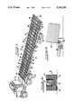
- FIG. 1is a perspective view of a trailer constructed in accordance with the principles of the present invention.
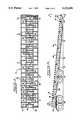
- FIG. 2is a top or plan view of the trailer of FIG. 1.
- FIG. 3is a side or elevational view of the trailer of FIGS. 1 and 2 in its tail-down configuration.
- FIG. 4is an end view of the trailer of FIGS. 1-3 as seen from the line 4--4 in FIG. 3.
- FIG. 5is a sectional view as seen from the line 5--5 of FIG. 4, with a load shown in the process of being unloaded.
- FIGS. 6 through 15are each side views on a reduced scale a conventional tractor and the trailer of FIGS. 1-4 with a load, showing successive steps in the unloading process at a building site. These views are especially useful in illustrating the distinctive manner of unloading of the present invention.
- FIG. 1there is depicted a trailer generally designated by the number 10.
- the trailer 10is shown in FIG. 1 in its over-the-road configuration, coupled to a conventional tractor or prime mover unit 12.
- the trailer 10is of the flatbed type but has a "bed" comprised of a set of rollers 14, 14', all of which are in the same plane as better shown in FIG. 3, and are supported on a frame 16.
- the frame 16includes a pair of main longitudinal members or beams 18, 20 which run parallel to one another at an equal distance from the longitudinal center line (about one-quarter of the trailer width) of the trailer.
- a number of cross members 22are connected between the main members.
- the frame 16also includes a pair of side members 24, 26 which are connected to the main member by a series of short cross members 28.
- the short cross members 28may be formed as unitary extensions of the cross members 22, in which case, the main members 18 and 20 are cut to receive them, and they are then welded in place to those members.
- the frame 16includes a front cross member 30 and has a conventional trailer-tractor connector unit 32 including a conventional kingpin for connecting to the conventional tractor unit 12. This unit 12 is sometimes termed a "fifth wheel" in this art.
- the frame 16is open and the rollers 14, 14' are staggered, with the outside rollers 14 being somewhat shorter than the center rollers 14'. Three sets or rows of rollers are thus provided.
- staggered rollers and shorter than full-width rollersas is commonly done in prior roller bed trailers
- the outside rollers 14overlap the ends of the center rollers 14' to leave no part of the transverse extent of the trailer load surface unsupported.
- the frame 16includes triangular bracing members 29, as is conventional for flatbed trailer frames.
- the tail end of the trailer 10is formed by a single large roller 14T which does extend across the width of the trailer. As will be explained below, this is the last roller which contacts and supports a load during unloading and thus is constructed in a substantial manner so as to support up to half or more of the expected load during the unloading process.
- the main frame members 18, 20are shaped to taper toward the tail and also each support on their bottom a track 34 which is part of the mounting for a tandem-wheeled carriage 36.
- the carriage 36itself, may be entirely conventional and thus need not be described in detail. It may be, for example, the carriage currently commercially available and known as a hitch sliding axle, single leaf spring carriage employing 5" round Rockwell brand #TKN4670-Q axles with Stenco brand grit guard oil sales and 121/2 ⁇ 85/8 non-asbestos brakes.
- Such unitsconventionally include rollers for contacting a flat surface of the track 34 and manually-releasable locking pins that project into holes in the track.
- the height of the carriage 36is less than that of a conventional drive wheel carriage 12C (FIG. 3) of a conventional tractor 12.
- the trailer "bed" of rollers 14, 14', 14Tslants rearward slightly in the over-the-road configuration.
- the track or slide rails 34extends for a considerable portion of the length of the frame 16, and the carriage may be shifted along the truck from the position shown in FIG. 2 to that of FIG. 3.
- the construction of the frame members and the height of the carriage 36 relative to that of the connector unit 32causes the frame 16 to pivot downward about the unit 12 to allow its tail to contact the ground.
- a novel arrangementis provided for contacting and moving the tail on the ground.
- Thisis a pair of rollers 40, one on each side of the tail just forward and below the last roller 14R.
- These ground rollers 40are, as shown in FIG. 4, situated between the main frame members 18, 20 and the outer side members 24, 26 and project below the level of the frame 16.
- these rollers and the main tractor unit 12provide the support for the trailer 10 and its load, and thus it is desirable to place these rollers at the tail end of the trailer 10. (Although they could be placed further toward the front, if desired, just so long as they contact the ground first when the carriage advances and sufficient support is provided to the tail roller 14R and the tail to prevent it from bending down and contacting the ground.)
- the height "h” of the roller 14T off of the ground when the trailer is in its tail-down positionis much less than the over-the-road height. In a 45'-long trailer prototype, this is only 12 inches above a flat unloading surface.
- a long loadsuch as the trusses 50 shown in FIG. 5 and FIGS. 6-15
- the effective dropis less than even this height, since its other end is already on the ground, its center of gravity typically drops only half of this distance.
- thishas been demonstrated to be entirely acceptable (being typically less of a shock than the conventional drop by a typical crane operator) and to not result in any damage to the load.
- FIGS. 6 through 15illustrate the success unloading a load of trusses 50 from the trailer 10 in accordance with the present invention.
- the tractor 12 with a loaded trailer 10has arrived at a building site.
- the equipment 60 and personnel which might be used to unload the trailer 10are not readily available.
- the driverwould have to wait or come back again.
- the drivercould attempt to "jerk" and drop off the load several feet and risk load damage.
- the driverneed only align and point the tail of the trailer toward an area, such as the area 62 where it is desired to leave the load 50. He then unlocks the carriage 36 and, as shown in FIG. 7, applies the brakes to its wheels while backing up the tractor 10. This lowers the tail end to have the tail rollers 40 contact the ground (FIG. 8).
- the drivercan back up or move forward the trailer in this arrangement so as to "place" the load almost exactly where he wants it.
- heremoves the straps (FIG. 9) and then drives the rig 10-12 forward from a standing stop.
- the natural inertia of the loadcauses it to tend to remain in place, and the trailer 10 rolls out from under it.
- some forward momentummay be transferred to the load, but in any case, as soon as the load makes contact with the ground, that contact tends to brake and hold the load from going forward. (FIG. 10)
- the load 50then actually propels or pushes the trailer forward (FIGS. 11 and 12) until the forward end of the load 50 rides over the tail roller 14T and drops to the ground (FIG. 13).
- the drivermay next apply the brakes to the wheels of the carriage 36 while driving forward (FIGS. 13 and 14) to raise the tail and return the trailer to its over-the-road state. He then stops and re-locks the carriage 36 in place and drives off to pick up a new load (FIG. 15).
- This entire unloading processcan be done by one man, the truck driver, in as little as ten minutes.
- a prototype trailerwas constructed substantially in accordance with the drawings. This trailer was tested and shown to perform well.
- the prototypewas about 45 feet long, with side members 24, 26 formed of 13/4-inch by 6-inch steel channels.
- the main members 18, 20were about 45-feet-long specially-fabricated I-beams substantially as shown, with a 6-inch wide top and bottom and being a maximum height of 19 inches.
- the cross members 22, 28were formed of 4-inch Jr. I-beams.
- the rollers 14were 47-inch long rollers, 2 inches in diameter, supported by LPR Westron brand end supports, with longitudinal and transverse bracing.
- the rollers 14'were 24 inches long and 2 inches in diameter and similarly supported. Both rollers 14 and 14' employed section 80 steel machine tubing at their outer surfaces.
- the roller 14Twas 7 inches in diameter.
- the rollers 40were 12 inches in diameter.
- the carriage 36was that previously identified.
- the track 34was formed of conventional track material for such a carriage but was made 26 feet long by adding an extension of 11 feet to the front of the conventional track.
- the brake air hose for the carriagewas run between the members 28, 20, and three 36-inch coil springs used to hold the hose in position and so as to prevent it from tangling or kinking as the carriage moves relative to the frame.
- the conventional trailer connectorstands at about 34 inches off the ground, so with the carriage 36 being about 17 inches high, the over-the-road pitch of the rollers 14, 14', 14T was about three degrees from the horizontal when on flat ground. When in its tail-down configuration (FIG. 3), the pitch is about seven degrees to the horizontal.
Landscapes
- Engineering & Computer Science (AREA)
- Transportation (AREA)
- Mechanical Engineering (AREA)
- Loading Or Unloading Of Vehicles (AREA)
Abstract
Description
Claims (3)
Priority Applications (1)
| Application Number | Priority Date | Filing Date | Title |
|---|---|---|---|
| US07/685,622US5102286A (en) | 1986-09-18 | 1991-04-15 | Trailer and trailer unloading system |
Applications Claiming Priority (3)
| Application Number | Priority Date | Filing Date | Title |
|---|---|---|---|
| US06/908,821US4806061A (en) | 1986-09-18 | 1986-09-18 | Trailer and trailer unloading system |
| US07/305,062US5009567A (en) | 1986-09-18 | 1989-02-02 | Trailer and trailer unloading system |
| US07/685,622US5102286A (en) | 1986-09-18 | 1991-04-15 | Trailer and trailer unloading system |
Related Parent Applications (1)
| Application Number | Title | Priority Date | Filing Date |
|---|---|---|---|
| US07/305,062DivisionUS5009567A (en) | 1986-09-18 | 1989-02-02 | Trailer and trailer unloading system |
Publications (1)
| Publication Number | Publication Date |
|---|---|
| US5102286Atrue US5102286A (en) | 1992-04-07 |
Family
ID=27405071
Family Applications (1)
| Application Number | Title | Priority Date | Filing Date |
|---|---|---|---|
| US07/685,622Expired - LifetimeUS5102286A (en) | 1986-09-18 | 1991-04-15 | Trailer and trailer unloading system |
Country Status (1)
| Country | Link |
|---|---|
| US (1) | US5102286A (en) |
Cited By (34)
| Publication number | Priority date | Publication date | Assignee | Title |
|---|---|---|---|---|
| GB2322620A (en)* | 1997-02-27 | 1998-09-02 | Robert Stuart Evans | A skip trailer |
| US6746199B2 (en) | 2001-10-16 | 2004-06-08 | Paul Jennings Carawan | Adjustable system and method for facilitating handling of cargo |
| US20060285958A1 (en)* | 2005-06-09 | 2006-12-21 | Wilhelm Robert C | Roller bed trailer having width extension rollers |
| US7465143B1 (en) | 2006-06-21 | 2008-12-16 | Adams Bill J | Load control system for a roll off trailer |
| US20090220325A1 (en)* | 2008-03-02 | 2009-09-03 | Jason Eugene Berney | Tilting Flatbed Trailer for Loading, Transporting, Unloading and Placement of Heavy Field Equipment |
| KR101194551B1 (en) | 2007-06-14 | 2012-10-24 | 지우룽 호우 | Integral compartment vehicle body |
| US8690517B1 (en) | 2008-09-11 | 2014-04-08 | Mcelroy Manufacturing, Inc. | Rack type pipe feeder for a pipe fusion machine |
| US20150224905A1 (en)* | 2014-02-07 | 2015-08-13 | Oren Technologies, Llc | Trailer-mounted proppant delivery system |
| US9162603B2 (en) | 2011-12-21 | 2015-10-20 | Oren Technologies, Llc | Methods of storing and moving proppant at location adjacent rail line |
| USRE45914E1 (en) | 2012-11-02 | 2016-03-08 | Oren Technologies, Llc | Proppant vessel |
| US9340353B2 (en) | 2012-09-27 | 2016-05-17 | Oren Technologies, Llc | Methods and systems to transfer proppant for fracking with reduced risk of production and release of silica dust at a well site |
| US9394102B2 (en) | 2012-07-23 | 2016-07-19 | Oren Technologies, Llc | Proppant discharge system and a container for use in such a proppant discharge system |
| US9394106B2 (en) | 2006-09-08 | 2016-07-19 | Mcelroy Manufacturing, Inc. | Rack type pipe feeder for a pipe fusion machine |
| US9403626B2 (en) | 2011-12-21 | 2016-08-02 | Oren Technologies, Llc | Proppant storage vessel and assembly thereof |
| US9446801B1 (en) | 2013-04-01 | 2016-09-20 | Oren Technologies, Llc | Trailer assembly for transport of containers of proppant material |
| US9624030B2 (en) | 2014-06-13 | 2017-04-18 | Oren Technologies, Llc | Cradle for proppant container having tapered box guides |
| USRE46381E1 (en) | 2012-11-02 | 2017-05-02 | Oren Technologies, Llc | Proppant vessel base |
| US9670752B2 (en) | 2014-09-15 | 2017-06-06 | Oren Technologies, Llc | System and method for delivering proppant to a blender |
| US9676554B2 (en) | 2014-09-15 | 2017-06-13 | Oren Technologies, Llc | System and method for delivering proppant to a blender |
| US9718610B2 (en) | 2012-07-23 | 2017-08-01 | Oren Technologies, Llc | Proppant discharge system having a container and the process for providing proppant to a well site |
| USRE46576E1 (en) | 2013-05-17 | 2017-10-24 | Oren Technologies, Llc | Trailer for proppant containers |
| USRE46590E1 (en) | 2013-05-17 | 2017-10-31 | Oren Technologies, Llc | Train car for proppant containers |
| US9809381B2 (en) | 2012-07-23 | 2017-11-07 | Oren Technologies, Llc | Apparatus for the transport and storage of proppant |
| USRE46613E1 (en) | 2012-11-02 | 2017-11-28 | Oren Technologies, Llc | Proppant vessel |
| US9845210B2 (en) | 2016-01-06 | 2017-12-19 | Oren Technologies, Llc | Conveyor with integrated dust collector system |
| USRE46645E1 (en) | 2013-04-05 | 2017-12-26 | Oren Technologies, Llc | Trailer for proppant containers |
| USRE47162E1 (en) | 2012-11-02 | 2018-12-18 | Oren Technologies, Llc | Proppant vessel |
| USD847489S1 (en) | 2012-09-24 | 2019-05-07 | Sandbox Logistics, Llc | Proppant container |
| US10518828B2 (en) | 2016-06-03 | 2019-12-31 | Oren Technologies, Llc | Trailer assembly for transport of containers of proppant material |
| US20210300228A1 (en)* | 2020-03-31 | 2021-09-30 | Brandt Industries Inc. | Trailer with kicker rollers |
| US20210331616A1 (en)* | 2020-04-28 | 2021-10-28 | Marion Body Works, Inc. | Freight transport carrier |
| US11623830B1 (en) | 2022-04-27 | 2023-04-11 | Modology Design Group | Trailer with loading and unloading system |
| US11873160B1 (en) | 2014-07-24 | 2024-01-16 | Sandbox Enterprises, Llc | Systems and methods for remotely controlling proppant discharge system |
| US12203279B2 (en) | 2022-04-27 | 2025-01-21 | Modology Design Group | Trailer with loading and unloading system |
Citations (18)
| Publication number | Priority date | Publication date | Assignee | Title |
|---|---|---|---|---|
| DE215731C (en)* | ||||
| DE248032C (en)* | ||||
| US1509530A (en)* | 1922-10-25 | 1924-09-23 | Shirreff Arthur Forbes | Transport lorry and other vehicle |
| GB516562A (en)* | 1937-03-24 | 1940-01-05 | Ugo Cristofoletti | Improvements relating to the loading of containers on road or like vehicles |
| US2693286A (en)* | 1952-02-06 | 1954-11-02 | Gertrude Eva M Cocks | Cargo handling apparatus for vehicles |
| US2717707A (en)* | 1952-06-27 | 1955-09-13 | William E Martin | Tilting platform trailer |
| US2738103A (en)* | 1955-06-29 | 1956-03-13 | Bisese John Pasqual | Package dispensing apparatus |
| US2753064A (en)* | 1955-04-05 | 1956-07-03 | Harold M Lesser | Trailer tiltable on longitudinally shiftable axle mounting |
| US2859889A (en)* | 1957-05-15 | 1958-11-11 | Richard R Love | Easy loading shifting axle trailer |
| US3209879A (en)* | 1965-10-05 | Best available copy | ||
| US3606059A (en)* | 1969-12-15 | 1971-09-20 | Herbert Haberle Jr | Roll-off trailer |
| US3934740A (en)* | 1973-10-29 | 1976-01-27 | Rumell James A | Transport vehicle with tiltable chassis |
| US4125198A (en)* | 1977-05-10 | 1978-11-14 | Landoll Corporation | Trailer having shiftable undercarriage |
| JPS56120421A (en)* | 1980-02-22 | 1981-09-21 | Suehiro Sharyo Seisakusho:Kk | Trailer |
| US4348150A (en)* | 1980-05-19 | 1982-09-07 | Fmc Corporation | Mobile cargo handling system and method |
| US4542815A (en)* | 1983-11-03 | 1985-09-24 | Lear Siegler, Inc. | Air brake and retarder for gravity conveyors |
| US4568235A (en)* | 1984-12-13 | 1986-02-04 | Dakota Manufacturing Co., Inc. | Low angle tilt trailer |
| US4599040A (en)* | 1983-02-22 | 1986-07-08 | Accurate Industries, Inc. | Method for transporting containers |
- 1991
- 1991-04-15USUS07/685,622patent/US5102286A/ennot_activeExpired - Lifetime
Patent Citations (18)
| Publication number | Priority date | Publication date | Assignee | Title |
|---|---|---|---|---|
| US3209879A (en)* | 1965-10-05 | Best available copy | ||
| DE248032C (en)* | ||||
| DE215731C (en)* | ||||
| US1509530A (en)* | 1922-10-25 | 1924-09-23 | Shirreff Arthur Forbes | Transport lorry and other vehicle |
| GB516562A (en)* | 1937-03-24 | 1940-01-05 | Ugo Cristofoletti | Improvements relating to the loading of containers on road or like vehicles |
| US2693286A (en)* | 1952-02-06 | 1954-11-02 | Gertrude Eva M Cocks | Cargo handling apparatus for vehicles |
| US2717707A (en)* | 1952-06-27 | 1955-09-13 | William E Martin | Tilting platform trailer |
| US2753064A (en)* | 1955-04-05 | 1956-07-03 | Harold M Lesser | Trailer tiltable on longitudinally shiftable axle mounting |
| US2738103A (en)* | 1955-06-29 | 1956-03-13 | Bisese John Pasqual | Package dispensing apparatus |
| US2859889A (en)* | 1957-05-15 | 1958-11-11 | Richard R Love | Easy loading shifting axle trailer |
| US3606059A (en)* | 1969-12-15 | 1971-09-20 | Herbert Haberle Jr | Roll-off trailer |
| US3934740A (en)* | 1973-10-29 | 1976-01-27 | Rumell James A | Transport vehicle with tiltable chassis |
| US4125198A (en)* | 1977-05-10 | 1978-11-14 | Landoll Corporation | Trailer having shiftable undercarriage |
| JPS56120421A (en)* | 1980-02-22 | 1981-09-21 | Suehiro Sharyo Seisakusho:Kk | Trailer |
| US4348150A (en)* | 1980-05-19 | 1982-09-07 | Fmc Corporation | Mobile cargo handling system and method |
| US4599040A (en)* | 1983-02-22 | 1986-07-08 | Accurate Industries, Inc. | Method for transporting containers |
| US4542815A (en)* | 1983-11-03 | 1985-09-24 | Lear Siegler, Inc. | Air brake and retarder for gravity conveyors |
| US4568235A (en)* | 1984-12-13 | 1986-02-04 | Dakota Manufacturing Co., Inc. | Low angle tilt trailer |
Cited By (101)
| Publication number | Priority date | Publication date | Assignee | Title |
|---|---|---|---|---|
| GB2322620A (en)* | 1997-02-27 | 1998-09-02 | Robert Stuart Evans | A skip trailer |
| US6746199B2 (en) | 2001-10-16 | 2004-06-08 | Paul Jennings Carawan | Adjustable system and method for facilitating handling of cargo |
| US20060285958A1 (en)* | 2005-06-09 | 2006-12-21 | Wilhelm Robert C | Roller bed trailer having width extension rollers |
| US7465143B1 (en) | 2006-06-21 | 2008-12-16 | Adams Bill J | Load control system for a roll off trailer |
| US9393739B2 (en) | 2006-09-08 | 2016-07-19 | McElroy Manufacturing , Inc. | Rack type pipe feeder for a pipe fusion machine |
| US9394106B2 (en) | 2006-09-08 | 2016-07-19 | Mcelroy Manufacturing, Inc. | Rack type pipe feeder for a pipe fusion machine |
| KR101194551B1 (en) | 2007-06-14 | 2012-10-24 | 지우룽 호우 | Integral compartment vehicle body |
| US20090220325A1 (en)* | 2008-03-02 | 2009-09-03 | Jason Eugene Berney | Tilting Flatbed Trailer for Loading, Transporting, Unloading and Placement of Heavy Field Equipment |
| US8690517B1 (en) | 2008-09-11 | 2014-04-08 | Mcelroy Manufacturing, Inc. | Rack type pipe feeder for a pipe fusion machine |
| US10538381B2 (en) | 2011-09-23 | 2020-01-21 | Sandbox Logistics, Llc | Systems and methods for bulk material storage and/or transport |
| US10562702B2 (en) | 2011-09-23 | 2020-02-18 | Sandbox Logistics, Llc | Systems and methods for bulk material storage and/or transport |
| US9643774B2 (en) | 2011-12-21 | 2017-05-09 | Oren Technologies, Llc | Proppant storage vessel and assembly thereof |
| US9682815B2 (en) | 2011-12-21 | 2017-06-20 | Oren Technologies, Llc | Methods of storing and moving proppant at location adjacent rail line |
| US9932181B2 (en) | 2011-12-21 | 2018-04-03 | Oren Technologies, Llc | Method of delivering, transporting, and storing proppant for delivery and use at a well site |
| US9162603B2 (en) | 2011-12-21 | 2015-10-20 | Oren Technologies, Llc | Methods of storing and moving proppant at location adjacent rail line |
| US9358916B2 (en) | 2011-12-21 | 2016-06-07 | Oren Technologies, Llc | Methods of storing and moving proppant at location adjacent rail line |
| US9403626B2 (en) | 2011-12-21 | 2016-08-02 | Oren Technologies, Llc | Proppant storage vessel and assembly thereof |
| US9914602B2 (en) | 2011-12-21 | 2018-03-13 | Oren Technologies, Llc | Methods of storing and moving proppant at location adjacent rail line |
| US9248772B2 (en) | 2011-12-21 | 2016-02-02 | Oren Technologies, Llc | Method of delivering, transporting, and storing proppant for delivery and use at a well site |
| US10703587B2 (en) | 2011-12-21 | 2020-07-07 | Oren Technologies, Llc | Method of delivering, transporting, and storing proppant for delivery and use at a well site |
| US9475661B2 (en) | 2011-12-21 | 2016-10-25 | Oren Technologies, Llc | Methods of storing and moving proppant at location adjacent rail line |
| US9511929B2 (en) | 2011-12-21 | 2016-12-06 | Oren Technologies, Llc | Proppant storage vessel and assembly thereof |
| US9527664B2 (en) | 2011-12-21 | 2016-12-27 | Oren Technologies, Llc | Proppant storage vessel and assembly thereof |
| US9617066B2 (en) | 2011-12-21 | 2017-04-11 | Oren Technologies, Llc | Method of delivering, transporting, and storing proppant for delivery and use at a well site |
| US9725234B2 (en) | 2012-07-23 | 2017-08-08 | Oren Technologies, Llc | Proppant discharge system and a container for use in such a proppant discharge system |
| US10814767B2 (en) | 2012-07-23 | 2020-10-27 | Oren Technologies, Llc | Trailer-mounted proppant delivery system |
| US9440785B2 (en) | 2012-07-23 | 2016-09-13 | Oren Technologies, Llc | Method of delivering, storing, unloading, and using proppant at a well site |
| US10745194B2 (en) | 2012-07-23 | 2020-08-18 | Oren Technologies, Llc | Cradle for proppant container having tapered box guides and associated methods |
| US9656799B2 (en) | 2012-07-23 | 2017-05-23 | Oren Technologies, Llc | Method of delivering, storing, unloading, and using proppant at a well site |
| US10661981B2 (en) | 2012-07-23 | 2020-05-26 | Oren Technologies, Llc | Proppant discharge system and a container for use in such a proppant discharge system |
| US9669993B2 (en) | 2012-07-23 | 2017-06-06 | Oren Technologies, Llc | Proppant discharge system and a container for use in such a proppant discharge system |
| US10661980B2 (en) | 2012-07-23 | 2020-05-26 | Oren Technologies, Llc | Method of delivering, storing, unloading, and using proppant at a well site |
| US10787312B2 (en) | 2012-07-23 | 2020-09-29 | Oren Technologies, Llc | Apparatus for the transport and storage of proppant |
| US9694970B2 (en) | 2012-07-23 | 2017-07-04 | Oren Technologies, Llc | Proppant discharge system and a container for use in such a proppant discharge system |
| US9701463B2 (en) | 2012-07-23 | 2017-07-11 | Oren Technologies, Llc | Method of delivering, storing, unloading, and using proppant at a well site |
| US9718609B2 (en) | 2012-07-23 | 2017-08-01 | Oren Technologies, Llc | Proppant discharge system and a container for use in such a proppant discharge system |
| US9718610B2 (en) | 2012-07-23 | 2017-08-01 | Oren Technologies, Llc | Proppant discharge system having a container and the process for providing proppant to a well site |
| US9725233B2 (en) | 2012-07-23 | 2017-08-08 | Oren Technologies, Llc | Proppant discharge system and a container for use in such a proppant discharge system |
| US10662006B2 (en) | 2012-07-23 | 2020-05-26 | Oren Technologies, Llc | Proppant discharge system having a container and the process for providing proppant to a well site |
| USRE46334E1 (en) | 2012-07-23 | 2017-03-07 | Oren Technologies, Llc | Proppant discharge system and a container for use in such a proppant discharge system |
| US9809381B2 (en) | 2012-07-23 | 2017-11-07 | Oren Technologies, Llc | Apparatus for the transport and storage of proppant |
| US9758081B2 (en) | 2012-07-23 | 2017-09-12 | Oren Technologies, Llc | Trailer-mounted proppant delivery system |
| US9771224B2 (en) | 2012-07-23 | 2017-09-26 | Oren Technologies, Llc | Support apparatus for moving proppant from a container in a proppant discharge system |
| US9862551B2 (en) | 2012-07-23 | 2018-01-09 | Oren Technologies, Llc | Methods and systems to transfer proppant for fracking with reduced risk of production and release of silica dust at a well site |
| US9738439B2 (en) | 2012-07-23 | 2017-08-22 | Oren Technologies, Llc | Proppant discharge system and a container for use in such a proppant discharge system |
| US10464741B2 (en) | 2012-07-23 | 2019-11-05 | Oren Technologies, Llc | Proppant discharge system and a container for use in such a proppant discharge system |
| US10569953B2 (en) | 2012-07-23 | 2020-02-25 | Oren Technologies, Llc | Proppant discharge system and a container for use in such a proppant discharge system |
| US9815620B2 (en) | 2012-07-23 | 2017-11-14 | Oren Technologies, Llc | Proppant discharge system and a container for use in such a proppant discharge system |
| US9394102B2 (en) | 2012-07-23 | 2016-07-19 | Oren Technologies, Llc | Proppant discharge system and a container for use in such a proppant discharge system |
| US9834373B2 (en) | 2012-07-23 | 2017-12-05 | Oren Technologies, Llc | Proppant discharge system and a container for use in such a proppant discharge system |
| US10239436B2 (en)* | 2012-07-23 | 2019-03-26 | Oren Technologies, Llc | Trailer-mounted proppant delivery system |
| US9969564B2 (en) | 2012-07-23 | 2018-05-15 | Oren Technologies, Llc | Methods and systems to transfer proppant for fracking with reduced risk of production and release of silica dust at a well site |
| USD847489S1 (en) | 2012-09-24 | 2019-05-07 | Sandbox Logistics, Llc | Proppant container |
| US9340353B2 (en) | 2012-09-27 | 2016-05-17 | Oren Technologies, Llc | Methods and systems to transfer proppant for fracking with reduced risk of production and release of silica dust at a well site |
| USRE46381E1 (en) | 2012-11-02 | 2017-05-02 | Oren Technologies, Llc | Proppant vessel base |
| USRE45914E1 (en) | 2012-11-02 | 2016-03-08 | Oren Technologies, Llc | Proppant vessel |
| USRE46613E1 (en) | 2012-11-02 | 2017-11-28 | Oren Technologies, Llc | Proppant vessel |
| USRE47162E1 (en) | 2012-11-02 | 2018-12-18 | Oren Technologies, Llc | Proppant vessel |
| USRE46531E1 (en) | 2012-11-02 | 2017-09-05 | Oren Technologies, Llc | Proppant vessel base |
| US10059246B1 (en) | 2013-04-01 | 2018-08-28 | Oren Technologies, Llc | Trailer assembly for transport of containers of proppant material |
| US9446801B1 (en) | 2013-04-01 | 2016-09-20 | Oren Technologies, Llc | Trailer assembly for transport of containers of proppant material |
| US9796319B1 (en) | 2013-04-01 | 2017-10-24 | Oren Technologies, Llc | Trailer assembly for transport of containers of proppant material |
| USRE46645E1 (en) | 2013-04-05 | 2017-12-26 | Oren Technologies, Llc | Trailer for proppant containers |
| USRE46590E1 (en) | 2013-05-17 | 2017-10-31 | Oren Technologies, Llc | Train car for proppant containers |
| USRE46576E1 (en) | 2013-05-17 | 2017-10-24 | Oren Technologies, Llc | Trailer for proppant containers |
| US9421899B2 (en)* | 2014-02-07 | 2016-08-23 | Oren Technologies, Llc | Trailer-mounted proppant delivery system |
| US20150224905A1 (en)* | 2014-02-07 | 2015-08-13 | Oren Technologies, Llc | Trailer-mounted proppant delivery system |
| US9624030B2 (en) | 2014-06-13 | 2017-04-18 | Oren Technologies, Llc | Cradle for proppant container having tapered box guides |
| US9840366B2 (en) | 2014-06-13 | 2017-12-12 | Oren Technologies, Llc | Cradle for proppant container having tapered box guides |
| US11873160B1 (en) | 2014-07-24 | 2024-01-16 | Sandbox Enterprises, Llc | Systems and methods for remotely controlling proppant discharge system |
| US9670752B2 (en) | 2014-09-15 | 2017-06-06 | Oren Technologies, Llc | System and method for delivering proppant to a blender |
| US9676554B2 (en) | 2014-09-15 | 2017-06-13 | Oren Technologies, Llc | System and method for delivering proppant to a blender |
| US10399789B2 (en) | 2014-09-15 | 2019-09-03 | Oren Technologies, Llc | System and method for delivering proppant to a blender |
| US10179703B2 (en) | 2014-09-15 | 2019-01-15 | Oren Technologies, Llc | System and method for delivering proppant to a blender |
| US9988215B2 (en) | 2014-09-15 | 2018-06-05 | Oren Technologies, Llc | System and method for delivering proppant to a blender |
| US10676296B2 (en) | 2016-01-06 | 2020-06-09 | Oren Technologies, Llc | Conveyor with integrated dust collector system |
| US10035668B2 (en) | 2016-01-06 | 2018-07-31 | Oren Technologies, Llc | Conveyor with integrated dust collector system |
| US9902576B1 (en) | 2016-01-06 | 2018-02-27 | Oren Technologies, Llc | Conveyor with integrated dust collector system |
| US10065816B2 (en) | 2016-01-06 | 2018-09-04 | Oren Technologies, Llc | Conveyor with integrated dust collector system |
| US11414282B2 (en) | 2016-01-06 | 2022-08-16 | Sandbox Enterprises, Llc | System for conveying proppant to a fracking site hopper |
| US9845210B2 (en) | 2016-01-06 | 2017-12-19 | Oren Technologies, Llc | Conveyor with integrated dust collector system |
| US9963308B2 (en) | 2016-01-06 | 2018-05-08 | Oren Technologies, Llc | Conveyor with integrated dust collector system |
| US9932183B2 (en) | 2016-01-06 | 2018-04-03 | Oren Technologies, Llc | Conveyor with integrated dust collector system |
| US9919882B2 (en) | 2016-01-06 | 2018-03-20 | Oren Technologies, Llc | Conveyor with integrated dust collector system |
| US10926967B2 (en) | 2016-01-06 | 2021-02-23 | Sandbox Enterprises, Llc | Conveyor with integrated dust collector system |
| US9868598B2 (en) | 2016-01-06 | 2018-01-16 | Oren Technologies, Llc | Conveyor with integrated dust collector system |
| US10518828B2 (en) | 2016-06-03 | 2019-12-31 | Oren Technologies, Llc | Trailer assembly for transport of containers of proppant material |
| US20210300228A1 (en)* | 2020-03-31 | 2021-09-30 | Brandt Industries Inc. | Trailer with kicker rollers |
| US11745635B2 (en)* | 2020-03-31 | 2023-09-05 | Brandt Industries Inc. | Trailer with kicker rollers |
| US20210331616A1 (en)* | 2020-04-28 | 2021-10-28 | Marion Body Works, Inc. | Freight transport carrier |
| US11739508B1 (en) | 2022-04-27 | 2023-08-29 | Modology Design Group | Mobile modular home with a bladder tank support assembly |
| US11623830B1 (en) | 2022-04-27 | 2023-04-11 | Modology Design Group | Trailer with loading and unloading system |
| US11731551B1 (en) | 2022-04-27 | 2023-08-22 | Modology Design Group | Systems and methods for an automatic modular housing delivery system |
| US11781310B1 (en) | 2022-04-27 | 2023-10-10 | Modology Design Group | Modular home delivery system |
| US11781312B1 (en) | 2022-04-27 | 2023-10-10 | Modology Design Group | Systems and methods for rotating a modular home on a trailer |
| US11787650B1 (en) | 2022-04-27 | 2023-10-17 | Modology Design Group | Trailer with loading and unloading system |
| US11828058B2 (en) | 2022-04-27 | 2023-11-28 | Modology Design Group | Trailer for modular home delivery and assembly |
| US11732463B1 (en) | 2022-04-27 | 2023-08-22 | Modology Design Group | Systems and methods for rotating modular housing modules on a trailer bed |
| US12203279B2 (en) | 2022-04-27 | 2025-01-21 | Modology Design Group | Trailer with loading and unloading system |
| US12270213B2 (en) | 2022-04-27 | 2025-04-08 | Modology Design Group | Systems and methods for unloading a structure |
| US12352035B2 (en) | 2022-04-27 | 2025-07-08 | Modology Design Group | Systems and methods for rotating a modular home on a trailer |
Similar Documents
| Publication | Publication Date | Title |
|---|---|---|
| US5102286A (en) | Trailer and trailer unloading system | |
| US4806061A (en) | Trailer and trailer unloading system | |
| CA1088123A (en) | Multiple hook-up, movable axle, container cargo trailer | |
| US5186596A (en) | Loading and unloading apparatus | |
| US5593272A (en) | Roll on roll off device with a portable support | |
| US3704798A (en) | Truck cargo transfer assembly | |
| US5088875A (en) | Roll-off hoist for variable positioning of containers | |
| US4599040A (en) | Method for transporting containers | |
| US4060145A (en) | Lift bed trailer suspension subframe | |
| US2996206A (en) | Vehicular loader | |
| US2858950A (en) | Heavy duty bed ramp trailer | |
| US4203697A (en) | Transfer apparatus for palletized loads | |
| AU2004200399B2 (en) | Front loading trailer and method of use | |
| US3993342A (en) | Convertible vehicle carrier | |
| US6386807B1 (en) | Stackable trailers | |
| US4537548A (en) | Combination hay hauler and stock trailer | |
| US4679979A (en) | Method of unloading large containers | |
| US5009567A (en) | Trailer and trailer unloading system | |
| US3618796A (en) | Vehicle loading and transport system | |
| US4122962A (en) | Trailer | |
| US2927704A (en) | Hydraulic device | |
| US4074822A (en) | Method and apparatus for transporting one vehicle by another | |
| US3981408A (en) | Apparatus for transporting one vehicle by another | |
| DE3123791A1 (en) | METHOD AND DEVICE FOR HANDLING AND TRANSPORTING, IN PARTICULAR BETWEEN A RO-RO SHIP AND A TERMINAL - A UNIT LOAD THAT CONSTITUTES ONE OR MORE CONTAINERS OR THE LIKE | |
| CA1301706C (en) | Trailer and trailer unloading system |
Legal Events
| Date | Code | Title | Description |
|---|---|---|---|
| REMI | Maintenance fee reminder mailed | ||
| FEPP | Fee payment procedure | Free format text:PETITION RELATED TO MAINTENANCE FEES FILED (ORIGINAL EVENT CODE: PMFP); ENTITY STATUS OF PATENT OWNER: LARGE ENTITY | |
| FEPP | Fee payment procedure | Free format text:PETITION RELATED TO MAINTENANCE FEES GRANTED (ORIGINAL EVENT CODE: PMFG); ENTITY STATUS OF PATENT OWNER: LARGE ENTITY | |
| REIN | Reinstatement after maintenance fee payment confirmed | ||
| FPAY | Fee payment | Year of fee payment:4 | |
| SULP | Surcharge for late payment | ||
| FP | Lapsed due to failure to pay maintenance fee | Effective date:19960410 | |
| STCF | Information on status: patent grant | Free format text:PATENTED CASE | |
| AS | Assignment | Owner name:AUTOMATION SALES, INC., INDIANA Free format text:ASSIGNMENT OF ASSIGNORS INTEREST;ASSIGNOR:FENTON, E. DALE;REEL/FRAME:008104/0546 Effective date:19860915 | |
| PRDP | Patent reinstated due to the acceptance of a late maintenance fee | Effective date:19960726 | |
| FEPP | Fee payment procedure | Free format text:PAT HLDR NO LONGER CLAIMS SMALL ENT STAT AS SMALL BUSINESS (ORIGINAL EVENT CODE: LSM2); ENTITY STATUS OF PATENT OWNER: LARGE ENTITY | |
| FPAY | Fee payment | Year of fee payment:8 | |
| AS | Assignment | Owner name:WABASH NATIONAL, L.P., INDIANA Free format text:ASSIGNMENT OF ASSIGNORS INTEREST;ASSIGNOR:WABASH NATIONAL CORPORATION;REEL/FRAME:010804/0743 Effective date:19991028 | |
| AS | Assignment | Owner name:WABASH TECHNOLOGY CORP., ILLINOIS Free format text:ASSIGNMENT OF ASSIGNORS INTEREST;ASSIGNOR:WABASH NATIONAL, L.P.;REEL/FRAME:010742/0238 Effective date:19991028 | |
| FPAY | Fee payment | Year of fee payment:12 | |
| AS | Assignment | Owner name:FLEET CAPITAL CORPORATION, AS AGENT, ILLINOIS Free format text:SECURITY AGREEMENT;ASSIGNOR:WABASH TECHNOLOGY CORPORATION;REEL/FRAME:014515/0870 Effective date:20030923 | |
| AS | Assignment | Owner name:WABASH NATIONAL, L.P., INDIANA Free format text:ASSIGNMENT OF ASSIGNORS INTEREST;ASSIGNOR:WABASH TECHNOLOGY CORPORATION;REEL/FRAME:014845/0817 Effective date:20031223 |