US5102079A - Connecting assembly for a tripod - Google Patents
Connecting assembly for a tripodDownload PDFInfo
- Publication number
- US5102079A US5102079AUS07/735,676US73567691AUS5102079AUS 5102079 AUS5102079 AUS 5102079AUS 73567691 AUS73567691 AUS 73567691AUS 5102079 AUS5102079 AUS 5102079A
- Authority
- US
- United States
- Prior art keywords
- connector
- lug
- locking bar
- prongs
- disposed
- Prior art date
- Legal status (The legal status is an assumption and is not a legal conclusion. Google has not performed a legal analysis and makes no representation as to the accuracy of the status listed.)
- Expired - Fee Related
Links
Images


Classifications
- F—MECHANICAL ENGINEERING; LIGHTING; HEATING; WEAPONS; BLASTING
- F16—ENGINEERING ELEMENTS AND UNITS; GENERAL MEASURES FOR PRODUCING AND MAINTAINING EFFECTIVE FUNCTIONING OF MACHINES OR INSTALLATIONS; THERMAL INSULATION IN GENERAL
- F16M—FRAMES, CASINGS OR BEDS OF ENGINES, MACHINES OR APPARATUS, NOT SPECIFIC TO ENGINES, MACHINES OR APPARATUS PROVIDED FOR ELSEWHERE; STANDS; SUPPORTS
- F16M11/00—Stands or trestles as supports for apparatus or articles placed thereon ; Stands for scientific apparatus such as gravitational force meters
- F16M11/20—Undercarriages with or without wheels
- F16M11/24—Undercarriages with or without wheels changeable in height or length of legs, also for transport only, e.g. by means of tubes screwed into each other
- F16M11/242—Undercarriages with or without wheels changeable in height or length of legs, also for transport only, e.g. by means of tubes screwed into each other by spreading of the legs
- F—MECHANICAL ENGINEERING; LIGHTING; HEATING; WEAPONS; BLASTING
- F16—ENGINEERING ELEMENTS AND UNITS; GENERAL MEASURES FOR PRODUCING AND MAINTAINING EFFECTIVE FUNCTIONING OF MACHINES OR INSTALLATIONS; THERMAL INSULATION IN GENERAL
- F16M—FRAMES, CASINGS OR BEDS OF ENGINES, MACHINES OR APPARATUS, NOT SPECIFIC TO ENGINES, MACHINES OR APPARATUS PROVIDED FOR ELSEWHERE; STANDS; SUPPORTS
- F16M11/00—Stands or trestles as supports for apparatus or articles placed thereon ; Stands for scientific apparatus such as gravitational force meters
- F16M11/02—Heads
- F16M11/16—Details concerning attachment of head-supporting legs, with or without actuation of locking members thereof
- Y—GENERAL TAGGING OF NEW TECHNOLOGICAL DEVELOPMENTS; GENERAL TAGGING OF CROSS-SECTIONAL TECHNOLOGIES SPANNING OVER SEVERAL SECTIONS OF THE IPC; TECHNICAL SUBJECTS COVERED BY FORMER USPC CROSS-REFERENCE ART COLLECTIONS [XRACs] AND DIGESTS
- Y10—TECHNICAL SUBJECTS COVERED BY FORMER USPC
- Y10T—TECHNICAL SUBJECTS COVERED BY FORMER US CLASSIFICATION
- Y10T403/00—Joints and connections
- Y10T403/32—Articulated members
- Y10T403/32254—Lockable at fixed position
- Y10T403/32262—At selected angle
- Y10T403/32319—At selected angle including pivot stud
- Y10T403/32327—At selected angle including pivot stud including radially spaced detent or latch component
- Y10T403/32336—Engaging notch or recess in outer periphery of component
Definitions
- the present inventionrelates to a tripod and more particularly to an improved connecting assembly for a tripod which can support a heavy article for a long period of time.
- a conventional tripod 10comprises a base seat 11, and three legs 12a, 12b, and 12c.
- the base seat 11comprises three lugs 112a, 112b, and 112c which are disposed on the outer periphery of a pipe 111.
- the angle between adjacent two lugs 112a and 112b, 112b and 112c, and 112c and 112ais 120 degrees.
- Each lug 112a, 112b, and 112chas three holes 113, 114, and 115, respectively.
- a clevis type connector 13a, 13b, and 13cis disposed at on the upper end of each respective leg 12a, 12b, and 12c.
- the shapes of the three connectors 13a, 13b, and 13care the same, with each clevis type connector 13a, 13b, and 13c having two lobe shaped prongs 131a and 131b.
- Prong 131ahas a hole 133
- prong 131bhas a hole 133 and a recess 135.
- Recess 135has a hole 134 and two screw holes 136a and 136b.
- a positioning assembly 14comprises an axle pin 111, a retaining ring 142, a locking pin 143 with a ring 144 disposed at one end, a spring 145, a plate 146, and two screws 147a and 147b.
- Lug 112ais inserted into space 132, and an axle pin 141 which passes through the pair of holes 133 and hole 113 is secured thereon by retaining ring 142.
- One end of locking pin 143is inserted into hole 134 and one of the two holes 114 or 115.
- locking pin 143passes through spring 145 and positioning plate 146 so that ring 144 is exposed.
- the tripodmay become unstable and collapse.
- the positioning pins 143are the only fulcrum points between base seat 11 and legs 12a, 12b, and 12c, respectively, the legs will tend to be unsteady under a heavy load.
- the principal object of the present inventionis to provide an improved connecting assembly for a tripod which can support a heavy article on the top of a central rod stably.
- the improved connecting assemblyhas improved connecting means which can support the tripod stably.
- the direction of the supporting force of each locking elementis along the radial direction of each respective lug. Since the locking element is disposed along the radial direction of the lug, the connecting and supporting means is strong enough to support a heavy article on the top of a central rod.
- FIG. 1is a perspective exploded view of a conventional tripod structure.
- FIG. 2is a perspective exploded view of a preferred embodiment of the improved connecting assembly for a tripod of the present invention.
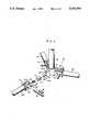
- FIG. 3is a cross-sectional view taken along line 1--1 of FIG. 1 showing an upper end of a leg locked in position with a lug, of a preferred embodiment of the improved connecting assembly for a tripod of the present invention.
- an improved connecting assembly for a tripod 20comprises a coupling pipe 29 secured on one end to a base seat 21 which has a pipe 211 with three lugs 22a, 22b, and 22c, three tubular supporting legs 23a, 23b, and 23c, three positioning elements 27, and three clevis type connectors 24.
- the three lugs 22a, 22b, and 22care disposed on the outer periphery of pipe 111.
- the angle between adjacent lugs 22a and 22b, 22b and 22c, and 22c and 22ais 120 degrees.
- Each lug 22a, 22b, and 22chas a pivot hole 221 and three recesses 222a, 222b, and 222c which are spacedly disposed around the periphery of each respective lug.
- a connector 24is disposed on the upper end of each leg 12a, 12b, and 12c, being secured thereon by the friction fitting of a round pipe coupler 246, formed at the rear of each connector 24, into the open upper end of a respective tubular supporting leg.
- the shape and connection means of the three connectors 24are the same.
- Each clevis type connector 24has two lobe-shaped prongs 241a and 241b.
- a space 242is formed between the prongs 241a and 241b.
- a cavity 245is formed on the base of connector 24 below space 242, extending into the pipe coupling 246 to the rear of connector 24.
- a locking bar 27 and a spring 28are disposed in cavity 245 with the locking bar 27 situated between the lug 22a and the spring 28.
- the forward end of locking bar 27abuts recess 222a, 222b, or 222c.
- the direction of the supporting force of each locking bar 27is along the radial direction of each supporting lug 23a, 23b, or 23c.
- a hole 271is formed on the side of the locking bar 27.
- Two through holes 243are formed in respective lobe-shaped prongs 241a and 241b.
- Two oval-shaped holes 244are formed in prongs, 241a and 241b, respectively.
- the lug 22ais inserted into space 242 with pivot hole 221 aligned with the two substantially equal with that of the two through holes 243 and slightly less than that of pivot hole 221, is forceably inserted through the first through hole 243 and the second through hole 243 to secure the axle pin 25 thereto by friction fit.
- the axle pin 25also passes through the pivot hole 221 to rotatably secure the connector 23a to lug 22a.
- a round bar 26passes through the first oval-shaped hole 244, the hole 271, and the second oval-shaped hole 244.
- a usercan pull rod 26 backwards towards leg 23a to move locking bar 27 away from lug 22a and rotate leg 23a about lug 22a until locking bar 27 is aligned with a selected locking recess 222a, 222b, or 222c.
- locking bar 27moves forward to abut against the selected locking recess and secure leg 23a and lug 22a in relative position.
- Rod 26can subsequently be removed and reinserted through hole 271 when a new position is desired. Pulling back on rod 26 will once again allow rotation of leg 23a about lug 22a.
- the height and tilt of the tripod 20can be adjusted.
- the leg 23ais parallel with support pipe 29.
- the tripod 20can be readily transported or stored.
- Various fixtures for attaching instrumentation or other articlesmay be secured to support pipe 29 as required.
Landscapes
- Engineering & Computer Science (AREA)
- General Engineering & Computer Science (AREA)
- Mechanical Engineering (AREA)
- Accessories Of Cameras (AREA)
Abstract
Description
The present invention relates to a tripod and more particularly to an improved connecting assembly for a tripod which can support a heavy article for a long period of time.
Referring to FIG. 1, aconventional tripod 10 comprises abase seat 11, and threelegs 12a, 12b, and 12c. Thebase seat 11 comprises threelugs pipe 111. The angle between adjacent twolugs lug holes
Aclevis type connector 13a, 13b, and 13c is disposed at on the upper end of eachrespective leg 12a, 12b, and 12c. The shapes of the threeconnectors 13a, 13b, and 13c are the same, with eachclevis type connector 13a, 13b, and 13c having two lobe shapedprongs hole 133, andprong 131b has ahole 133 and arecess 135.Recess 135 has ahole 134 and twoscrew holes
Apositioning assembly 14 comprises anaxle pin 111, aretaining ring 142, alocking pin 143 with aring 144 disposed at one end, aspring 145, aplate 146, and twoscrews
Lug 112a is inserted intospace 132, and anaxle pin 141 which passes through the pair ofholes 133 andhole 113 is secured thereon by retainingring 142. One end oflocking pin 143 is inserted intohole 134 and one of the twoholes
The other end of lockingpin 143 passes throughspring 145 and positioningplate 146 so thatring 144 is exposed.
Two screws, 147a and 147b, pass throughpositioning plate 146 and secure intoscrew holes
If a heavy article is secured to the top ofcentral rod 15, the tripod may become unstable and collapse. As thepositioning pins 143 are the only fulcrum points betweenbase seat 11 andlegs 12a, 12b, and 12c, respectively, the legs will tend to be unsteady under a heavy load.
The principal object of the present invention is to provide an improved connecting assembly for a tripod which can support a heavy article on the top of a central rod stably.
Accordingly, the improved connecting assembly has improved connecting means which can support the tripod stably. The direction of the supporting force of each locking element is along the radial direction of each respective lug. Since the locking element is disposed along the radial direction of the lug, the connecting and supporting means is strong enough to support a heavy article on the top of a central rod.
FIG. 1 is a perspective exploded view of a conventional tripod structure.
FIG. 2 is a perspective exploded view of a preferred embodiment of the improved connecting assembly for a tripod of the present invention.
FIG. 3 is a cross-sectional view taken along line 1--1 of FIG. 1 showing an upper end of a leg locked in position with a lug, of a preferred embodiment of the improved connecting assembly for a tripod of the present invention.
Referring to FIG. 2, an improved connecting assembly for atripod 20 comprises acoupling pipe 29 secured on one end to abase seat 21 which has apipe 211 with threelugs legs positioning elements 27, and threeclevis type connectors 24. The threelugs pipe 111. The angle betweenadjacent lugs lug pivot hole 221 and threerecesses connector 24 is disposed on the upper end of eachleg 12a, 12b, and 12c, being secured thereon by the friction fitting of a round pipe coupler 246, formed at the rear of eachconnector 24, into the open upper end of a respective tubular supporting leg. The shape and connection means of the threeconnectors 24 are the same. Eachclevis type connector 24 has two lobe-shaped prongs space 242 is formed between theprongs
Referring to FIGS. 2 and 3, acavity 245 is formed on the base ofconnector 24 belowspace 242, extending into the pipe coupling 246 to the rear ofconnector 24. Alocking bar 27 and aspring 28 are disposed incavity 245 with thelocking bar 27 situated between thelug 22a and thespring 28. When thetripod 20 is in use, the forward end oflocking bar 27 abuts recess 222a, 222b, or 222c. Thus the direction of the supporting force of eachlocking bar 27 is along the radial direction of each supportinglug
Ahole 271 is formed on the side of thelocking bar 27. Two throughholes 243 are formed in respective lobe-shaped prongs shaped holes 244 are formed in prongs, 241a and 241b, respectively. Thelug 22a is inserted intospace 242 withpivot hole 221 aligned with the two substantially equal with that of the two throughholes 243 and slightly less than that ofpivot hole 221, is forceably inserted through the first throughhole 243 and the second throughhole 243 to secure theaxle pin 25 thereto by friction fit. Theaxle pin 25 also passes through thepivot hole 221 to rotatably secure theconnector 23a to lug 22a. Around bar 26 passes through the first oval-shaped hole 244, thehole 271, and the second oval-shaped hole 244.
Whereby, a user can pullrod 26 backwards towardsleg 23a to movelocking bar 27 away fromlug 22a and rotateleg 23a aboutlug 22a untillocking bar 27 is aligned with a selectedlocking recess locking bar 27 moves forward to abut against the selected locking recess and secureleg 23a and lug 22a in relative position.
Claims (1)
1. An improved connecting assembly for a tripod comprising:
a base seat with a pipe and a first, second, and third lugs, said lugs being disposed on the outer periphery of said pipe;
a first, second, and third support legs, each said support leg having a clevis type connector secured to the upper end thereof;
each said connector having a first and second prongs with a space formed between said first and second prongs;
a cavity is formed on the base of each said connector, below said space;
a spring and a locking bar are disposed within each said cavity with said spring disposed to the rear of said cavity and said locking bar disposed to the front thereof;
a hole is formed in the side of each said locking bar;
a first and second oval shaped holes are formed on said first and second prongs of each said connector, respectively;
a first and second through holes are formed on said first and second prongs of each said connector, respectively;
a first, second, and third locking recesses are spacedly formed around the outer periphery of each said lug;
a pivot hole is formed on each said lug;
each said lug is disposed within said space between said prongs of respective said connectors;
an axle pin passes through said first and second through holes of respective said first and second prongs of each said connector, and through said pivot hole of each said lug;
a said axle pin is rigidly secured to said first and second through holes of each said connector, rotatably securing each said connector to a respective said lug;
a rod is passed through said first and second oval shaped holes of each said connector, and passes through said hole of a respective said locking bar of each said connector;
whereby, a user can pull a said rod to the rear, separating a respective said locking bar from a respective said lug, and rotate respective said leg and attached said connector about said lug until a selected said locking recess of said lug is aligned with said locking bar, upon release said locking bar moves forward and abuts said locking recess to secure said leg and said lug in relative position, said locking bar can subsequently be removed from said hole of locking bar and reinserted when a change of position of said leg is desired.
Priority Applications (1)
| Application Number | Priority Date | Filing Date | Title |
|---|---|---|---|
| US07/735,676US5102079A (en) | 1990-11-23 | 1991-07-29 | Connecting assembly for a tripod |
Applications Claiming Priority (2)
| Application Number | Priority Date | Filing Date | Title |
|---|---|---|---|
| US61736090A | 1990-11-23 | 1990-11-23 | |
| US07/735,676US5102079A (en) | 1990-11-23 | 1991-07-29 | Connecting assembly for a tripod |
Related Parent Applications (1)
| Application Number | Title | Priority Date | Filing Date |
|---|---|---|---|
| US61736090AContinuation | 1990-11-23 | 1990-11-23 |
Publications (1)
| Publication Number | Publication Date |
|---|---|
| US5102079Atrue US5102079A (en) | 1992-04-07 |
Family
ID=27088012
Family Applications (1)
| Application Number | Title | Priority Date | Filing Date |
|---|---|---|---|
| US07/735,676Expired - Fee RelatedUS5102079A (en) | 1990-11-23 | 1991-07-29 | Connecting assembly for a tripod |
Country Status (1)
| Country | Link |
|---|---|
| US (1) | US5102079A (en) |
Cited By (37)
| Publication number | Priority date | Publication date | Assignee | Title |
|---|---|---|---|---|
| US5213296A (en)* | 1992-02-03 | 1993-05-25 | Lee Jin T | Structure improved connecting assembly for tripod |
| US5310145A (en)* | 1992-10-19 | 1994-05-10 | Jason Chen | Floor lamp tripod stand |
| US5340066A (en)* | 1993-01-12 | 1994-08-23 | American Trading And Production Corporation | Stand for article |
| US5340068A (en)* | 1992-08-05 | 1994-08-23 | Marketing Displays, Inc. | Release mechanism for locking pivotable leg |
| US5611509A (en)* | 1994-11-22 | 1997-03-18 | Traffix Devices, Inc. | Quick release mechanism for a display stand |
| US5645272A (en)* | 1993-12-22 | 1997-07-08 | Kimrick, Incorporated | Lifting and positioning device for cabinets and construction panels |
| US5823491A (en)* | 1995-03-10 | 1998-10-20 | Vitec Group Plc | Spreader unit for multi-legged stands |
| US6131971A (en)* | 1998-08-21 | 2000-10-17 | Chen; Kao-San | Foldable spade |
| US6131749A (en)* | 1999-02-15 | 2000-10-17 | Crockett; Stanley B. | Adjustable clothes rack |
| US6161807A (en)* | 1995-09-27 | 2000-12-19 | Steiner; Michael | Portable optometric support stand |
| US6206387B1 (en)* | 1998-12-30 | 2001-03-27 | Shui-Te Tsai | Collapsible skateboard |
| US6315253B1 (en) | 1999-12-07 | 2001-11-13 | Dicke Tool Company | Foldable supporting device and quick release mechanism therefor |
| US6598840B1 (en)* | 1998-05-13 | 2003-07-29 | Bs-Ausstellungstechnik Gmbh | Presentation device |
| US6619606B2 (en)* | 1999-06-07 | 2003-09-16 | Innovative Office Products, Inc. | Arm apparatus for mounting electronic devices with cable management system |
| US6685156B2 (en)* | 2002-05-15 | 2004-02-03 | Dicke Tool Company | Quick release mechanism for use with a supporting device |
| US20040135043A1 (en)* | 2003-01-14 | 2004-07-15 | Ultimate Support Systems, Inc. | Off-axis reducible support structure |
| US6793191B1 (en)* | 2003-07-09 | 2004-09-21 | Dicke Tool Company | Quick release mechanism for use with a supporting device |
| US20040255826A1 (en)* | 2003-04-09 | 2004-12-23 | Kent Ashby | Table |
| US20050056740A1 (en)* | 2003-08-29 | 2005-03-17 | Louis Chuang | Rack for bicycle |
| US7677515B2 (en) | 2004-07-07 | 2010-03-16 | Innovative Office Products, Inc. | Arm apparatus with reinforcement |
| USD692963S1 (en) | 2012-08-30 | 2013-11-05 | Razor Usa Llc | Scooter |
| US20140238747A1 (en)* | 2013-02-25 | 2014-08-28 | Paul J. Fabian | Auger stand for a utility truck and method of using same |
| US8870200B2 (en) | 2012-03-27 | 2014-10-28 | Razor Usa, Llc | Scooter with rear swivel wheel |
| ITBO20130429A1 (en)* | 2013-08-01 | 2015-02-02 | Penta Vi Di Aluigi Lorenzo | DEVICE FOR SUPPORTING A SPORTS EQUIPMENT |
| US9518696B1 (en)* | 2016-04-28 | 2016-12-13 | Shyang Yung Plastics Co., Ltd. | Rack structure for a rack assembly |
| US9770098B1 (en)* | 2016-12-11 | 2017-09-26 | Prospect Furniture LLC | Table leg connection |
| USD815215S1 (en) | 2016-09-08 | 2018-04-10 | Razor Usa Llc | Scooter |
| US20180274716A1 (en)* | 2012-09-26 | 2018-09-27 | Access Products Group LLC | Quick release connector |
| US10119654B2 (en)* | 2015-04-16 | 2018-11-06 | Kevin McDermott | Tripod appliance |
| US10161706B2 (en)* | 2016-12-23 | 2018-12-25 | Magpul Industries Corp. | Firearm bipod |
| US10168119B2 (en)* | 2016-12-23 | 2019-01-01 | Magpul Industries Corp. | Firearm bipod |
| US10436426B2 (en)* | 2017-09-22 | 2019-10-08 | Jacob M Thomas | Foldable portable lamp |
| US10526034B2 (en) | 2016-09-02 | 2020-01-07 | Razor Usa Llc | Anti-rattle folding scooter |
| US11419420B1 (en)* | 2021-07-15 | 2022-08-23 | Wudi Industrial (Shanghai) Co., Ltd. | Highly stable seat chassis |
| US11856347B1 (en) | 2020-01-16 | 2023-12-26 | David M. Roberts | Speaker stand |
| USD1051999S1 (en) | 2019-05-28 | 2024-11-19 | Razor Usa Llc | Scooter |
| EP4201599B1 (en)* | 2021-12-22 | 2024-11-27 | Ronald Bosse | Working aid |
Citations (5)
| Publication number | Priority date | Publication date | Assignee | Title |
|---|---|---|---|---|
| US2634075A (en)* | 1949-10-27 | 1953-04-07 | Alphonso P Citro | Stand |
| US4010922A (en)* | 1976-01-02 | 1977-03-08 | Heller Thomas L | Portable post support |
| US4593879A (en)* | 1982-11-17 | 1986-06-10 | Marketing Displays, Inc. | Compact sign stand |
| US4796843A (en)* | 1987-11-05 | 1989-01-10 | Oconnor Chadwell | Cable tripod spreader |
| US4905946A (en)* | 1989-02-08 | 1990-03-06 | Wang Lai S | Adjustable leg assembly |
- 1991
- 1991-07-29USUS07/735,676patent/US5102079A/ennot_activeExpired - Fee Related
Patent Citations (5)
| Publication number | Priority date | Publication date | Assignee | Title |
|---|---|---|---|---|
| US2634075A (en)* | 1949-10-27 | 1953-04-07 | Alphonso P Citro | Stand |
| US4010922A (en)* | 1976-01-02 | 1977-03-08 | Heller Thomas L | Portable post support |
| US4593879A (en)* | 1982-11-17 | 1986-06-10 | Marketing Displays, Inc. | Compact sign stand |
| US4796843A (en)* | 1987-11-05 | 1989-01-10 | Oconnor Chadwell | Cable tripod spreader |
| US4905946A (en)* | 1989-02-08 | 1990-03-06 | Wang Lai S | Adjustable leg assembly |
Cited By (68)
| Publication number | Priority date | Publication date | Assignee | Title |
|---|---|---|---|---|
| US5213296A (en)* | 1992-02-03 | 1993-05-25 | Lee Jin T | Structure improved connecting assembly for tripod |
| US5340068A (en)* | 1992-08-05 | 1994-08-23 | Marketing Displays, Inc. | Release mechanism for locking pivotable leg |
| US5310145A (en)* | 1992-10-19 | 1994-05-10 | Jason Chen | Floor lamp tripod stand |
| US5340066A (en)* | 1993-01-12 | 1994-08-23 | American Trading And Production Corporation | Stand for article |
| US5645272A (en)* | 1993-12-22 | 1997-07-08 | Kimrick, Incorporated | Lifting and positioning device for cabinets and construction panels |
| US5611509A (en)* | 1994-11-22 | 1997-03-18 | Traffix Devices, Inc. | Quick release mechanism for a display stand |
| US5823491A (en)* | 1995-03-10 | 1998-10-20 | Vitec Group Plc | Spreader unit for multi-legged stands |
| US6161807A (en)* | 1995-09-27 | 2000-12-19 | Steiner; Michael | Portable optometric support stand |
| US6598840B1 (en)* | 1998-05-13 | 2003-07-29 | Bs-Ausstellungstechnik Gmbh | Presentation device |
| US6131971A (en)* | 1998-08-21 | 2000-10-17 | Chen; Kao-San | Foldable spade |
| US9422021B2 (en) | 1998-12-30 | 2016-08-23 | Razor Usa Llc | Collapsible skateboard |
| US7063341B2 (en) | 1998-12-30 | 2006-06-20 | Razor Usa Llc | Collapsible skateboard |
| US6431567B2 (en) | 1998-12-30 | 2002-08-13 | Shui-Te Tsai | Collapsible skateboard |
| US6206387B1 (en)* | 1998-12-30 | 2001-03-27 | Shui-Te Tsai | Collapsible skateboard |
| US20090322049A1 (en)* | 1998-12-30 | 2009-12-31 | Razor Usa, Llc | Collapsible skateboard |
| US7559561B2 (en) | 1998-12-30 | 2009-07-14 | Razor Usa Llc | Collapsible skateboard |
| US20060237934A1 (en)* | 1998-12-30 | 2006-10-26 | Shui-Te Tsai | Collapsible skateboard |
| US9969456B2 (en) | 1998-12-30 | 2018-05-15 | Razor Usa Llc | Collapsible skateboard |
| US8157275B2 (en) | 1998-12-30 | 2012-04-17 | Razor Usa, Llc | Collapsible skateboard |
| US8474840B2 (en) | 1998-12-30 | 2013-07-02 | Razor Usa, Llc | Collapsible skateboard |
| US6131749A (en)* | 1999-02-15 | 2000-10-17 | Crockett; Stanley B. | Adjustable clothes rack |
| US6619606B2 (en)* | 1999-06-07 | 2003-09-16 | Innovative Office Products, Inc. | Arm apparatus for mounting electronic devices with cable management system |
| US6315253B1 (en) | 1999-12-07 | 2001-11-13 | Dicke Tool Company | Foldable supporting device and quick release mechanism therefor |
| US6685156B2 (en)* | 2002-05-15 | 2004-02-03 | Dicke Tool Company | Quick release mechanism for use with a supporting device |
| US20050035247A1 (en)* | 2003-01-14 | 2005-02-17 | Ultimate Support Systems, Inc. | Reducible support structures having off-axis engagement |
| US6789772B2 (en)* | 2003-01-14 | 2004-09-14 | Ultimate Support Systems, Inc. | Off-axis reducible support structure |
| US20040135043A1 (en)* | 2003-01-14 | 2004-07-15 | Ultimate Support Systems, Inc. | Off-axis reducible support structure |
| US20040255826A1 (en)* | 2003-04-09 | 2004-12-23 | Kent Ashby | Table |
| US7063025B2 (en)* | 2003-04-09 | 2006-06-20 | Lifetime Products, Inc. | Table with foldable legs |
| US6793191B1 (en)* | 2003-07-09 | 2004-09-21 | Dicke Tool Company | Quick release mechanism for use with a supporting device |
| US20050056740A1 (en)* | 2003-08-29 | 2005-03-17 | Louis Chuang | Rack for bicycle |
| US7677515B2 (en) | 2004-07-07 | 2010-03-16 | Innovative Office Products, Inc. | Arm apparatus with reinforcement |
| US12084144B2 (en) | 2012-03-27 | 2024-09-10 | Razor Usa Llc | Scooter with rear swivel wheel |
| US11498636B2 (en) | 2012-03-27 | 2022-11-15 | Razor Usa Llc | Scooter with rear swivel wheel |
| US8870200B2 (en) | 2012-03-27 | 2014-10-28 | Razor Usa, Llc | Scooter with rear swivel wheel |
| US10661853B2 (en) | 2012-03-27 | 2020-05-26 | Razor Usa Llc | Scooter with rear swivel wheel |
| US9387900B2 (en) | 2012-03-27 | 2016-07-12 | Razor Usa Llc | Scooter with rear swivel wheel |
| US10099741B2 (en) | 2012-03-27 | 2018-10-16 | Razor Usa Llc | Scooter with rear swivel wheel |
| US9771115B2 (en) | 2012-03-27 | 2017-09-26 | Razor Usa Llc | Scooter with rear swivel wheel |
| USD717881S1 (en) | 2012-08-30 | 2014-11-18 | Razor Usa Llc | Scooter |
| USD692963S1 (en) | 2012-08-30 | 2013-11-05 | Razor Usa Llc | Scooter |
| US20180274716A1 (en)* | 2012-09-26 | 2018-09-27 | Access Products Group LLC | Quick release connector |
| US20140238747A1 (en)* | 2013-02-25 | 2014-08-28 | Paul J. Fabian | Auger stand for a utility truck and method of using same |
| ITBO20130429A1 (en)* | 2013-08-01 | 2015-02-02 | Penta Vi Di Aluigi Lorenzo | DEVICE FOR SUPPORTING A SPORTS EQUIPMENT |
| US10119654B2 (en)* | 2015-04-16 | 2018-11-06 | Kevin McDermott | Tripod appliance |
| US9518696B1 (en)* | 2016-04-28 | 2016-12-13 | Shyang Yung Plastics Co., Ltd. | Rack structure for a rack assembly |
| US11530012B2 (en) | 2016-09-02 | 2022-12-20 | Razor Usa Llc | Anti-rattle folding scooter |
| US10526034B2 (en) | 2016-09-02 | 2020-01-07 | Razor Usa Llc | Anti-rattle folding scooter |
| USD837303S1 (en) | 2016-09-08 | 2019-01-01 | Razor Usa Llc | Scooter |
| USD978255S1 (en) | 2016-09-08 | 2023-02-14 | Razor Usa Llc | Scooter kickstand |
| USD900241S1 (en) | 2016-09-08 | 2020-10-27 | Razor Usa Llc | Scooter |
| USD866675S1 (en) | 2016-09-08 | 2019-11-12 | Razor Usa Llc | Scooter |
| USD941396S1 (en) | 2016-09-08 | 2022-01-18 | Razor Usa Llc | Scooter |
| USD815215S1 (en) | 2016-09-08 | 2018-04-10 | Razor Usa Llc | Scooter |
| US9770098B1 (en)* | 2016-12-11 | 2017-09-26 | Prospect Furniture LLC | Table leg connection |
| US10739100B2 (en)* | 2016-12-23 | 2020-08-11 | Magpul Industries Corp. | Firearm bipod |
| US10627181B2 (en) | 2016-12-23 | 2020-04-21 | Magpul Industries Corp. | Firearm bipod |
| US20190086177A1 (en)* | 2016-12-23 | 2019-03-21 | Magpul Industries Corp. | Firearm bipod |
| US10168119B2 (en)* | 2016-12-23 | 2019-01-01 | Magpul Industries Corp. | Firearm bipod |
| US11732991B2 (en) | 2016-12-23 | 2023-08-22 | Magpul Industries Corp. | Firearm bipod |
| US11867473B2 (en) | 2016-12-23 | 2024-01-09 | Magpul Industries Corp. | Firearm bipod |
| US10161706B2 (en)* | 2016-12-23 | 2018-12-25 | Magpul Industries Corp. | Firearm bipod |
| US12422209B2 (en) | 2016-12-23 | 2025-09-23 | Magpul Industries Corp. | Firearm bipod |
| US10436426B2 (en)* | 2017-09-22 | 2019-10-08 | Jacob M Thomas | Foldable portable lamp |
| USD1051999S1 (en) | 2019-05-28 | 2024-11-19 | Razor Usa Llc | Scooter |
| US11856347B1 (en) | 2020-01-16 | 2023-12-26 | David M. Roberts | Speaker stand |
| US11419420B1 (en)* | 2021-07-15 | 2022-08-23 | Wudi Industrial (Shanghai) Co., Ltd. | Highly stable seat chassis |
| EP4201599B1 (en)* | 2021-12-22 | 2024-11-27 | Ronald Bosse | Working aid |
Similar Documents
| Publication | Publication Date | Title |
|---|---|---|
| US5102079A (en) | Connecting assembly for a tripod | |
| US5213296A (en) | Structure improved connecting assembly for tripod | |
| US6824319B1 (en) | Tripod particularly for optical and photographic use | |
| US4905946A (en) | Adjustable leg assembly | |
| US6871920B2 (en) | Quick-mount support system for telescoping slide | |
| EP1055380B1 (en) | A top board for tables, shelves or the like and a connector for board sections forming the top board or the like | |
| US4027987A (en) | Joining device for connecting tubes | |
| US5358204A (en) | Folding keyboard stand | |
| US4711003A (en) | Coupling system | |
| TW201838547A (en) | Front bracket quick release structure of server slide rail capable of swiveling and pivotally rotating a swivel buckle for installation or disassembly without using a tool | |
| US6293575B1 (en) | Foldable frame assembly for a bicycle | |
| EP0598718B1 (en) | Tripod | |
| EP0290784A1 (en) | Portable table | |
| KR100662454B1 (en) | Stand structure for flat panel display | |
| US7093809B2 (en) | Tool used for removing and fitting a transmission gear box | |
| GB2188691A (en) | Quick release plug | |
| US6193307B1 (en) | Folding chair | |
| JPH08506645A (en) | Angle head tripod mount | |
| US1120702A (en) | Table-leg socket. | |
| US20060049681A1 (en) | Releasable chair section securing assembly | |
| EP1228721B1 (en) | Ouick-on shelf support for furniture and the like | |
| US6254177B1 (en) | Foldable chair frame | |
| JP2009034383A (en) | buckle | |
| US11988322B2 (en) | Tripod design and manufacture | |
| US3061870A (en) | Releasable hinge latch for bed frames |
Legal Events
| Date | Code | Title | Description |
|---|---|---|---|
| REMI | Maintenance fee reminder mailed | ||
| LAPS | Lapse for failure to pay maintenance fees | ||
| FP | Lapsed due to failure to pay maintenance fee | Effective date:19960410 | |
| STCH | Information on status: patent discontinuation | Free format text:PATENT EXPIRED DUE TO NONPAYMENT OF MAINTENANCE FEES UNDER 37 CFR 1.362 |