US5099702A - Perimeter mounted polymeric piezoelectric transducer pad - Google Patents
Perimeter mounted polymeric piezoelectric transducer padDownload PDFInfo
- Publication number
- US5099702A US5099702AUS07/380,157US38015789AUS5099702AUS 5099702 AUS5099702 AUS 5099702AUS 38015789 AUS38015789 AUS 38015789AUS 5099702 AUS5099702 AUS 5099702A
- Authority
- US
- United States
- Prior art keywords
- side wall
- force
- transducer
- measuring device
- recited
- Prior art date
- Legal status (The legal status is an assumption and is not a legal conclusion. Google has not performed a legal analysis and makes no representation as to the accuracy of the status listed.)
- Expired - Lifetime
Links
- 230000008859changeEffects0.000claimsabstractdescription4
- 239000000463materialSubstances0.000claimsdescription36
- 238000011068loading methodMethods0.000claimsdescription21
- 230000033001locomotionEffects0.000claimsdescription18
- 239000006260foamSubstances0.000claimsdescription15
- 230000008878couplingEffects0.000claimsdescription12
- 238000010168coupling processMethods0.000claimsdescription12
- 238000005859coupling reactionMethods0.000claimsdescription12
- 239000004033plasticSubstances0.000claimsdescription6
- 229920003023plasticPolymers0.000claimsdescription6
- 230000002093peripheral effectEffects0.000claimsdescription5
- 239000012858resilient materialSubstances0.000claimsdescription3
- 229920003051synthetic elastomerPolymers0.000claimsdescription3
- 239000005061synthetic rubberSubstances0.000claimsdescription3
- 239000004820Pressure-sensitive adhesiveSubstances0.000claimsdescription2
- 229920003052natural elastomerPolymers0.000claimsdescription2
- 229920001194natural rubberPolymers0.000claimsdescription2
- 244000043261Hevea brasiliensisSpecies0.000claims1
- 239000013536elastomeric materialSubstances0.000claims1
- 239000010410layerSubstances0.000description14
- 238000012544monitoring processMethods0.000description11
- 230000009191jumpingEffects0.000description6
- 229920001971elastomerPolymers0.000description5
- 230000029058respiratory gaseous exchangeEffects0.000description5
- 239000005060rubberSubstances0.000description5
- 230000035945sensitivityEffects0.000description5
- 239000000853adhesiveSubstances0.000description4
- 230000001070adhesive effectEffects0.000description4
- 230000006870functionEffects0.000description4
- 238000005259measurementMethods0.000description4
- 229910052751metalInorganic materials0.000description4
- 239000002184metalSubstances0.000description4
- 230000035882stressEffects0.000description4
- 229920002799BoPETPolymers0.000description3
- 239000005041Mylar™Substances0.000description3
- 238000006243chemical reactionMethods0.000description3
- 230000000694effectsEffects0.000description3
- 239000005038ethylene vinyl acetateSubstances0.000description3
- 239000002985plastic filmSubstances0.000description3
- 229920000642polymerPolymers0.000description3
- 239000002023woodSubstances0.000description3
- 238000004458analytical methodMethods0.000description2
- 238000013459approachMethods0.000description2
- 230000037396body weightEffects0.000description2
- DQXBYHZEEUGOBF-UHFFFAOYSA-Nbut-3-enoic acid;etheneChemical compoundC=C.OC(=O)CC=CDQXBYHZEEUGOBF-UHFFFAOYSA-N0.000description2
- 239000000919ceramicSubstances0.000description2
- 238000000576coating methodMethods0.000description2
- 238000011156evaluationMethods0.000description2
- 230000003116impacting effectEffects0.000description2
- 230000001788irregularEffects0.000description2
- 150000002739metalsChemical class0.000description2
- 238000012806monitoring deviceMethods0.000description2
- 229920001200poly(ethylene-vinyl acetate)Polymers0.000description2
- 230000009467reductionEffects0.000description2
- 230000000241respiratory effectEffects0.000description2
- 239000007787solidSubstances0.000description2
- -1vinyl nitrileChemical class0.000description2
- 229920002554vinyl polymerPolymers0.000description2
- BQCIDUSAKPWEOX-UHFFFAOYSA-N1,1-DifluoroetheneChemical compoundFC(F)=CBQCIDUSAKPWEOX-UHFFFAOYSA-N0.000description1
- 229920001875EbonitePolymers0.000description1
- 229920006370KynarPolymers0.000description1
- 239000004743PolypropyleneSubstances0.000description1
- 229920009405Polyvinylidenefluoride (PVDF) FilmPolymers0.000description1
- 238000005299abrasionMethods0.000description1
- 239000012790adhesive layerSubstances0.000description1
- 230000032683agingEffects0.000description1
- 238000003491arrayMethods0.000description1
- 238000000418atomic force spectrumMethods0.000description1
- 229910002113barium titanateInorganic materials0.000description1
- 230000008827biological functionEffects0.000description1
- 230000005540biological transmissionEffects0.000description1
- 230000000903blocking effectEffects0.000description1
- 238000007664blowingMethods0.000description1
- 230000005792cardiovascular activityEffects0.000description1
- 230000009084cardiovascular functionEffects0.000description1
- 239000011248coating agentSubstances0.000description1
- 230000000052comparative effectEffects0.000description1
- 150000001875compoundsChemical class0.000description1
- 238000010276constructionMethods0.000description1
- 238000013016dampingMethods0.000description1
- 230000003247decreasing effectEffects0.000description1
- 238000001514detection methodMethods0.000description1
- 239000003989dielectric materialSubstances0.000description1
- 238000003618dip coatingMethods0.000description1
- 230000002526effect on cardiovascular systemEffects0.000description1
- 238000001914filtrationMethods0.000description1
- 230000005021gaitEffects0.000description1
- 239000003292glueSubstances0.000description1
- 230000005484gravityEffects0.000description1
- 238000009434installationMethods0.000description1
- 239000004579marbleSubstances0.000description1
- 239000012528membraneSubstances0.000description1
- 238000000034methodMethods0.000description1
- 238000012986modificationMethods0.000description1
- 230000004048modificationEffects0.000description1
- 230000000737periodic effectEffects0.000description1
- 229920006255plastic filmPolymers0.000description1
- 229920001155polypropylenePolymers0.000description1
- LJCNRYVRMXRIQR-OLXYHTOASA-Lpotassium sodium L-tartrateChemical compound[Na+].[K+].[O-]C(=O)[C@H](O)[C@@H](O)C([O-])=OLJCNRYVRMXRIQR-OLXYHTOASA-L0.000description1
- 239000010453quartzSubstances0.000description1
- 230000004202respiratory functionEffects0.000description1
- 230000035939shockEffects0.000description1
- VYPSYNLAJGMNEJ-UHFFFAOYSA-Nsilicon dioxideInorganic materialsO=[Si]=OVYPSYNLAJGMNEJ-UHFFFAOYSA-N0.000description1
- 229910052709silverInorganic materials0.000description1
- 239000004332silverSubstances0.000description1
- 235000011006sodium potassium tartrateNutrition0.000description1
- 230000037078sports performanceEffects0.000description1
- 238000012360testing methodMethods0.000description1
- 238000012549trainingMethods0.000description1
- 238000012546transferMethods0.000description1
- 125000000391vinyl groupChemical group[H]C([*])=C([H])[H]0.000description1
- 230000001755vocal effectEffects0.000description1
Images


Classifications
- A—HUMAN NECESSITIES
- A63—SPORTS; GAMES; AMUSEMENTS
- A63B—APPARATUS FOR PHYSICAL TRAINING, GYMNASTICS, SWIMMING, CLIMBING, OR FENCING; BALL GAMES; TRAINING EQUIPMENT
- A63B24/00—Electric or electronic controls for exercising apparatus of preceding groups; Controlling or monitoring of exercises, sportive games, training or athletic performances
- A63B24/0021—Tracking a path or terminating locations
- A—HUMAN NECESSITIES
- A61—MEDICAL OR VETERINARY SCIENCE; HYGIENE
- A61B—DIAGNOSIS; SURGERY; IDENTIFICATION
- A61B5/00—Measuring for diagnostic purposes; Identification of persons
- A61B5/103—Measuring devices for testing the shape, pattern, colour, size or movement of the body or parts thereof, for diagnostic purposes
- A61B5/1036—Measuring load distribution, e.g. podologic studies
- A—HUMAN NECESSITIES
- A61—MEDICAL OR VETERINARY SCIENCE; HYGIENE
- A61B—DIAGNOSIS; SURGERY; IDENTIFICATION
- A61B5/00—Measuring for diagnostic purposes; Identification of persons
- A61B5/103—Measuring devices for testing the shape, pattern, colour, size or movement of the body or parts thereof, for diagnostic purposes
- A61B5/11—Measuring movement of the entire body or parts thereof, e.g. head or hand tremor or mobility of a limb
- A61B5/1102—Ballistocardiography
- A—HUMAN NECESSITIES
- A61—MEDICAL OR VETERINARY SCIENCE; HYGIENE
- A61B—DIAGNOSIS; SURGERY; IDENTIFICATION
- A61B5/00—Measuring for diagnostic purposes; Identification of persons
- A61B5/103—Measuring devices for testing the shape, pattern, colour, size or movement of the body or parts thereof, for diagnostic purposes
- A61B5/11—Measuring movement of the entire body or parts thereof, e.g. head or hand tremor or mobility of a limb
- A61B5/113—Measuring movement of the entire body or parts thereof, e.g. head or hand tremor or mobility of a limb occurring during breathing
- A—HUMAN NECESSITIES
- A63—SPORTS; GAMES; AMUSEMENTS
- A63B—APPARATUS FOR PHYSICAL TRAINING, GYMNASTICS, SWIMMING, CLIMBING, OR FENCING; BALL GAMES; TRAINING EQUIPMENT
- A63B63/00—Targets or goals for ball games
- A—HUMAN NECESSITIES
- A63—SPORTS; GAMES; AMUSEMENTS
- A63B—APPARATUS FOR PHYSICAL TRAINING, GYMNASTICS, SWIMMING, CLIMBING, OR FENCING; BALL GAMES; TRAINING EQUIPMENT
- A63B69/00—Training appliances or apparatus for special sports
- A—HUMAN NECESSITIES
- A63—SPORTS; GAMES; AMUSEMENTS
- A63B—APPARATUS FOR PHYSICAL TRAINING, GYMNASTICS, SWIMMING, CLIMBING, OR FENCING; BALL GAMES; TRAINING EQUIPMENT
- A63B71/00—Games or sports accessories not covered in groups A63B1/00 - A63B69/00
- A63B71/06—Indicating or scoring devices for games or players, or for other sports activities
- A—HUMAN NECESSITIES
- A63—SPORTS; GAMES; AMUSEMENTS
- A63B—APPARATUS FOR PHYSICAL TRAINING, GYMNASTICS, SWIMMING, CLIMBING, OR FENCING; BALL GAMES; TRAINING EQUIPMENT
- A63B71/00—Games or sports accessories not covered in groups A63B1/00 - A63B69/00
- A63B71/08—Body-protectors for players or sportsmen, i.e. body-protecting accessories affording protection of body parts against blows or collisions
- A63B71/14—Body-protectors for players or sportsmen, i.e. body-protecting accessories affording protection of body parts against blows or collisions for the hands, e.g. baseball, boxing or golfing gloves
- G—PHYSICS
- G01—MEASURING; TESTING
- G01L—MEASURING FORCE, STRESS, TORQUE, WORK, MECHANICAL POWER, MECHANICAL EFFICIENCY, OR FLUID PRESSURE
- G01L1/00—Measuring force or stress, in general
- G01L1/16—Measuring force or stress, in general using properties of piezoelectric devices
- G—PHYSICS
- G01—MEASURING; TESTING
- G01L—MEASURING FORCE, STRESS, TORQUE, WORK, MECHANICAL POWER, MECHANICAL EFFICIENCY, OR FLUID PRESSURE
- G01L5/00—Apparatus for, or methods of, measuring force, work, mechanical power, or torque, specially adapted for specific purposes
- G01L5/14—Apparatus for, or methods of, measuring force, work, mechanical power, or torque, specially adapted for specific purposes for measuring the force of explosions; for measuring the energy of projectiles
- A—HUMAN NECESSITIES
- A61—MEDICAL OR VETERINARY SCIENCE; HYGIENE
- A61B—DIAGNOSIS; SURGERY; IDENTIFICATION
- A61B2503/00—Evaluating a particular growth phase or type of persons or animals
- A61B2503/10—Athletes
- A—HUMAN NECESSITIES
- A61—MEDICAL OR VETERINARY SCIENCE; HYGIENE
- A61B—DIAGNOSIS; SURGERY; IDENTIFICATION
- A61B2562/00—Details of sensors; Constructional details of sensor housings or probes; Accessories for sensors
- A61B2562/02—Details of sensors specially adapted for in-vivo measurements
- A61B2562/0219—Inertial sensors, e.g. accelerometers, gyroscopes, tilt switches
- A—HUMAN NECESSITIES
- A61—MEDICAL OR VETERINARY SCIENCE; HYGIENE
- A61B—DIAGNOSIS; SURGERY; IDENTIFICATION
- A61B2562/00—Details of sensors; Constructional details of sensor housings or probes; Accessories for sensors
- A61B2562/02—Details of sensors specially adapted for in-vivo measurements
- A61B2562/0247—Pressure sensors
- A—HUMAN NECESSITIES
- A63—SPORTS; GAMES; AMUSEMENTS
- A63B—APPARATUS FOR PHYSICAL TRAINING, GYMNASTICS, SWIMMING, CLIMBING, OR FENCING; BALL GAMES; TRAINING EQUIPMENT
- A63B24/00—Electric or electronic controls for exercising apparatus of preceding groups; Controlling or monitoring of exercises, sportive games, training or athletic performances
- A63B24/0021—Tracking a path or terminating locations
- A63B2024/0037—Tracking a path or terminating locations on a target surface or at impact on the ground
- A—HUMAN NECESSITIES
- A63—SPORTS; GAMES; AMUSEMENTS
- A63B—APPARATUS FOR PHYSICAL TRAINING, GYMNASTICS, SWIMMING, CLIMBING, OR FENCING; BALL GAMES; TRAINING EQUIPMENT
- A63B2220/00—Measuring of physical parameters relating to sporting activity
- A63B2220/50—Force related parameters
- A63B2220/51—Force
- A63B2220/53—Force of an impact, e.g. blow or punch
Definitions
- This inventionrelates to electromechanical transducers for measuring the magnitude of forces and for detecting changes in force, and, in particular, to polymeric piezoelectric transducer devices providing output information with regard to force, frequency, velocity, energy, work and power of objects in contact with or impinging upon the transducer device.
- the inventionfinds use in sports, medical and industrial applications.
- Various devicesare employed for detecting force or change in force and other characteristics related thereto. Exemplary of the range of such devices are force platforms in the biomedical, sports and industrial fields measuring large scale ground reaction forces, and seismographic mattresses in the medical fields detecting small scale cardiovascular and respiratory forces.
- Force platformsin particular, measure ground reaction forces in biomedical applications such as gait analysis, analysis of sway patterns in neurology, evaluation of sports performance, assessment of the degree of rehabilitation and numerous other medical, sports and industrial applications.
- These platformstypically use multiple strain gauges, capacitive sensors or load cells for sensing force and changes in force. Due in part to the inherent size limitations of the sensors, they cannot directly act as the load receiving surface and must be used in arrays and coupled to a platform surface, generally a rigid, light and very stiff planar member.
- One sensor for such force platformsis disclosed in U.S. Pat. No. 3,210,993 wherein a ceramic piezoelectric transducer encircles a solid metal cylindrical support column. The transducer is stressed in accordance with the radial expansion of the column caused by applied loading to the platform to generate a signal in accordance therewith. To achieve uniformity across the platform surface, complex circuitry is required to interpret the multiple sensor signals generated at each column.
- Seismographic mattressesare useful for monitoring patients' heart and respiration rates. These mattresses are non-invasive transducers for measuring these biological signals, thereby eliminating the need for restricting and psychologically intimidating sensor attachment to the patient.
- a sheet of transducer materialis placed under the mattress to measure these minute biological forces.
- the sensor materialmay be piezoelectric or capacitive film or the like.
- a medical apparatus for the monitoring of patient activity on a bedcomprises a flexible capacitive motion sensor placed under the patient mattress.
- the sensoruses an active layer, underlying the entire bottom surface of the mattress.
- the sensorconsists of two courses of dielectric material placed in contact with one another. Movements of the patient on top of the mattress cause the courses to move relative to one another, thereby generating an electric charge in the active layer.
- the electrical chargeis detected by a pair of metallized plastic sheets which form a capacitive antenna.
- the resultant systemis a sandwich of five discrete, mattress size layers all of which are shielded in a metallized plastic film bag.
- a detecting devicewhich is durable, inexpensive, and mechanically simple for measuring, with sensitivity and uniformity over a broad dynamic range, and displaying parameters relating to movement on a loading surface.
- the inventionprovides a detecting device which may be subjected to randomly located loadings and will uniformly supply an output related to various parameters thereof.
- a detecting device for detecting changes in loading in accordance with the inventioncomprises a load receiving member of a homogeneous material having a first or front face for experiencing the loading, a second face in opposed relation to said first face, and side wall means interconnecting said first face and said second face.
- a flexible polymeric piezoelectric transducer stripis disposed in stress receiving relationship with substantially the entire periphery of the side wall.
- the piezoelectric transducer stripis stressed in accordance with changes in said loading and yields an electrical output signal in accordance with said changes and characteristics of changes in the loading of the load receiving member.
- the load receiving membermay be a polymeric pad of circular, rectangular, oval or like rounded configuration.
- suitable materialsare natural and synthetic rubber, plastics, polymeric foams, and in general resilient materials which are locally deformable and substantially uniform in elastic constant.
- a matching of the material and the applicationis important.
- materials with higher elastic constantsyield lower voltages and higher frequency waveforms.
- Such materials when coupled with a perimeter mounted polymer piezoelectric transducer stripare useful in detecting and measuring higher loading changes, such as randomly located, high mass impacts.
- the lower elastic constant materialsyield higher voltage signals and lower frequency waveforms. These materials are useful in detecting and measuring lower level loading changes, such as seismographic mattresses and patient monitors.
- the elastic compliance of the polymeric piezoelectric film that engages the periphery of the padis many times that of piezoceramic materials. This enables good coupling of the sensor to the resilient support pad without disturbing the mechanical motion of the pad.
- the low mechanical and acoustic impedance of the polymeric piezoelectric film compared to piezoceramicsprovides efficient energy transfer to the sensor. The efficiency can be further improved by using a polymer adhesive to mount the sensor that has similar impedance values as the polymeric piezoelectric film.
- orientation of the sensor in relationship to the machine or stretch directioncan contribute to maximum generation of charge for a given applied force.
- the inventionorients the film so that forces acting on the load-receiving face cause an applied tensile stress in the direction of stretch, thereby accentuating the resulting charge produced for a given force.
- sheet devicesfor a given force acting on the face, cause a compressive stress that results in significantly lower charge generation.
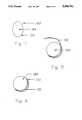
- FIG. 1is a top view of the force pad of circular construction according to the invention
- FIG. 2is a front view of a rectangular force pad according to the invention.
- FIG. 3is a front view of a square force pad with rounded corners according to the invention.
- FIG. 4is an irregular shaped force pad with piezoelectric sensor means applied to the perimeter thereof;
- FIG. 5is a perspective view of a piezoelectric means incorporated in a strap being applied to a round force pad;
- FIG. 6is a perspective view of a round force pad with a strap applied to the perimeter thereof;
- FIG. 7is a rectangular force pad with a piezoelectric means being applied to the perimeter thereof;
- FIG. 8is a rectangular force pad with rounded corners, and a piezoelectric sensor applied to the perimeter thereof;
- FIG. 9is a plan view of a circular force pad having a polymeric piezoelectric transducer strip applied to the perimeter thereof;
- FIG. 10is an enlarged fragmentary cross sectional view taken along line 10--10 in FIG. 9;
- FIG. 11is a perspective view of a flexible polymeric piezoelectric transducer strip in accordance with the present invention.
- FIG. 12is an enlarged cross sectional view taken along line 12--12 of FIG. 11;
- FIG. 13is a typical biological function wave form for a person lying on a force pad in accordance with the present invention.
- FIG. 14is a plan view of a seismographic mattress in accordance with the present invention.
- FIG. 15is a plan view of a force pad coupled to an output device.
- FIG. 16is a typical wave form for a person jumping on the force pad of FIG. 15.
- FIGS. 9 and 10show a perimeter mounted polymeric piezoelectric film transducer pad 10 comprising a circular cylindrical force pad 12 having a flexible polymeric piezoelectric transducer strip 14 mechanically coupled to the side wall 15 of the pad 12.
- the striphas output leads 16a and 16b operatively connected to an output device 18.
- the force pad 10measures, accurately and uniformly, loading changes caused by movement of an object 20, illustrated in dashed lines, randomly impacting or moving on a portion of the front surface 22 of the force pad 12 as detected by the strip 14 and output by the device 18.
- the rear or bottom surface 24 of the force pad 10is carried by a support member 26.
- Padsi.e. support structures generally defined by parallel top and bottom surfaces circumscribed by a peripheral side wall, are particularly good means for measuring the characteristics of impacts when the piezoelectric sensor means are used. It has been found that the piezoelectric means, preferably of the flexible polymeric piezoelectric film strip, can be used very advantageously with many different types of force pads. It is believed that impacts rendered on a force pad generate force waves which emanate substantially regularly throughout the pad, and that their measurement can yield the characteristics of the impact.
- the piezoelectric meanscan be permanently or removably affixed to the perimeter of the force pad.
- a foam or rubber force padcould be oriented vertically.
- a horizontal force pad made out of a hard rubber or resilient foam on which the person could jump or the likewould be appropriate.
- a foam padcould be mounted vertically to receive the person's fist, foot or body impacts.
- the leads and indicator devicesare not shown in FIGS. 1-4 for sake of clarity, but may be of the type discussed previously.
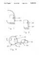
- FIG. 1shows a vertical force pad assembly 100 having a pad 102 and a piezoelectric assembly 104 as described above attached thereto.
- assembly 100When assembly 100 is made out of foam, rubber, or the like and suspended vertically, it could be used to measure baseballs pitched at it.
- the piezoelectric device 104could be an integral part of force pad 102, and the circumference could be 35 inches or larger.
- FIG. 4shows another force pad assembly 122 having a force pad 124 having an irregular shape, around which is attached a flexible piezoelectric transducer 126. If device 122 were made out of plastic or other foam and if large enough, it could be used for a blocking dummy for football players or a target for martial arts fighters. Soft force pads, yielding low frequencies but high voltages for impacts which they receive, are less resilient and more comfortable to engage.
- the piezoelectric filmmay be incorporated in a strap rather than being an inherent part of the force pad.
- a force pad 128has a piezoelectric film strip 130 being applied to it.
- the film strip 130is as described above but with perhaps a thicker Mylar coating, and its end has a Velcro patch or glue type adhesive for slightly overlapping the other end of the strap to yield a lapped or overlapped strap when connected.
- FIG. 6shows a force pad 128 with the strap firmly in place.
- FIG. 7shows a rectangular force pad 134 with a piezoelectric film strip 136 about to be adhered to its perimeter
- FIG. 8shows a rectangular force pad 138 having rounded corners with its strip 140 in place.
- the piezoelectric material referred to with respect to the various embodiments described hereinis preferably a polarized polyvinylidene fluoride (PVDF) film sandwiched between metallized layers of electrically conductive metal.
- PVDFpolyvinylidene fluoride
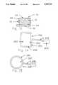
- the piezoelectric assembly 200comprises an elongate transducer strip 202 electrically coupled to a cable 204 at a connector housing 206.
- the cable 204terminates with a molded connector plug 208 adapted to be connected to the output device 18, referenced above.
- the transducer strip 202is a multilayer laminate comprising an outer Mylar layer 204, a middle polymeric piezoelectric sheet 206 having metallized coatings 208 and 210 on either side thereof, and an inner Mylar layer 212.
- the layers 212 and 204are adhesively attached to the sheet 206.
- the inner layermay be provided with an adhesive layer for coupling attachment to the pad, with the adhesive protected prior to installation by peel back release paper 214.
- the piezoelectric filmis approximately 28 microns in thickness, and the oppose metallized layers are silver of about 0.1 microns in thickness.
- the force pad 12 in FIG. 9is formed of a homogeneous material of substantially uniform elastic constant. While the force pad may be formed of high elastic constant materials such as metals, woods, and hard plastics, it is generally preferred to use polymeric materials, such as rubber, softer plastics, polymer foams and like materials having an elastic constant similar to the film strip and that are resilient and locally deformable to aid in wave energy propagation to the transducer strip 14.
- high elastic constant materialssuch as metals, woods, and hard plastics
- polymeric materialssuch as rubber, softer plastics, polymer foams and like materials having an elastic constant similar to the film strip and that are resilient and locally deformable to aid in wave energy propagation to the transducer strip 14.
- the force pad 10may be mounted, horizontally, vertically or inclined on a base member 26.
- the pad 12is cylindrically shaped defined by the front load receiving surface 22, a parallel spaced rear support surface 26, and bounded by a continuous side wall 28. While illustrated as circular, other cylindrical shapes (rectangular, rectangular with rounded corners, oval and the like) can be used for accurately and uniformly measuring changes in loading on any portion of the front surface 22.
- the side wallmay be truncated, although such shape increases the difficulty of achieving continuous mechanical coupling of the strip 14 to the side wall.
- the transducer strip 14is coupled to the side wall 28, mechanically, compressively or adhesively. Excellent coupling has been obtained through adhesive attachment using pressure sensitive adhesive supplied by 3M, such as Product No. Y-9485 for the polymeric foam pad, and Product No 950 for solid rubber pads.
- the strip 14 so coupledhas material properties well matched to the pad 14 and provides high piezoelectric sensitivity, low mechanical and acoustic impedance to produce accurate, ascertainable outputs to the device 18 throughout a broad range of loadings.
- the flexible polymeric piezoelectric strip 14provides many times the voltage output for a given force, enabling the sensing of movements as low as respiration and pulse. Moreover, because of the toughness and flexibility of the materials, the strip 14 is not subject to breakage or loss of dipolar properties when subjected to mechanical impact in velocity measuring embodiments described below.
- the strip 14may be located at various positions on the side wall. For the monitoring of respiration and pulse requiring sensing of low force changes, a location adjacent the top surface has been found most satisfactory. For large, heavy objects impacting the load receiving surface, location of the transducer strip 14 adjacent to the rear surface is preferred. Notwithstanding the foregoing, generally accurate output may be obtained without location dependency with the strip 14 located in intermediate positions along the side wall.
- the uniformity provided by continuous perimeter mounting of the transducer strip as provided by Pad 1is particularly important where uniformity and repeatability of information is desired, such as velocity targets and force platforms described below. Where detection of signal characteristics is desired, such as seismographic mattresses and patient monitors described below, the transducer strip should be mechanically coupled to the side wall along sufficient perimeter to output the selected characteristic with accuracy and distinction.
- the material selection for the pad to provide the mechanical coupling with the transduceris also important.
- Metals, ceramics, rigid plastics and like materialsunder tests similar to the above, show high location dependency, random peak amplitudes in the wave form, and polarity reversal. Such irregularities are experienced on both hard and resilient base surfaces. Typical results for such rigid materials are set forth in Example 2 below.
- a 1/2 inch by 12 inch circular polypropylene diskwas equipped with a continuous flexible piezoelectric transducer strip and tested in accordance with the conditions of Example 1. In one condition, the disk was supported on a wood surface and in another condition the disk was supported on a 1 inch thick polymeric foam pad.
- the pads of the present inventionwherein there is uniformity in the first peak signal, and substantially less significant second peak signals, the above were replete with numerous peak signals with very little damping of the signal until at least four peaks were determined on the wood surface, and two or more were determined on the foam support. It is thought that the wave propagation frequencies were so high and undampened that reverberations sensed throughout the sensor length interfered with a sensing of the prime impact signal.
- the support membershould not restrain the propagation of wave energy to the transducer strip. Mechanically or adhesively attaching the pad to the support member can create significant location dependencies, particularly in devices where the transducer strip is located adjacent to the support member such as in projectile measurement plates and ground reaction force plates. On the other hand, for measuring minute biological signals where it is preferred to locate the sensor adjacent to the supporting surface, only limited reduction in the quality of the output signal is observed.
- the force pad of the present inventionprovides extreme sensitivity to random loading on the top surface.
- EVAethylene vinyl acetate
- a common marble dropped from 12 inchesgenerated a peak output signal of 320 mv., merely blowing on the pad from 6 inches produced readily detectable 50 mv. peak output signals.
- a ballistic cardiograph signal of 40-100 mv.was regularly periodically outputted with a rise and fall of the peak in accordance with respiration.
- a typical signal of a person at restis shown in FIG. 13.
- a patient monitoring mattress 250comprises a deformable, locally compressible pad 252 which has a flexible polymeric piezoelectric transducer strip 254 mechanically coupled to the side wall 256.
- the top surface 258 of the padmay directly support the patient without the need for a conventional mattress.
- the bottom surface 260may be carried by conventional bedding support structure, or alternatively the pad 252 may be supported on a rigid base which in turn is carried by the bedding support structure.
- Electrodes 262 attached as described above to the transducer strip 254are connected to a suitable output device 264 which may comprise an oscilloscope, strip chart recorder, alarm device or the like. Additionally the output signals may be processed by filtering or comparative techniques as described in U.S. Pat. Nos. 4,686,999 and 4,320,766 to enhance evaluation of the output signal. Furthermore, it has been demonstrated that the transducer pad as described above has such extreme sensitivity as to enable vocal sounds to be transmitted through the pad and received by the transducer strip, such that if the output device 264 additionally includes a speaker system of the proper type, patient speech is also provided as output. Because of the sensitivity of the present invention to changes in loading, the device described above is useful in many patient monitoring situations, in addition to those referenced above. The device can be used for remote monitoring of gross body movement of the patient, patient presence on the device so as to accommodate continuous information as to the patient's status.
- the seismographic mattresses described aboveprovide clear output signal with low background noise when the transducer strip is mechanically coupled about substantially the entire perimeter of the mattress.
- the perimeter mounttypically employs a 1/4" wide band approximately 18 feet long so that only 54 square inches or approximately 0.38 square feet is needed.
- the present inventionrequires only approximately 2% of the film, or a savings of 98%. It has been determined that the transducer strip length can be reduced to provide further cost advantages. Moreover, a reduction in length does not diminish the signal to noise ratio.
- an 81 inch by 33 inch EVA foam mattress 3 inches thickas supplied by Rubatex Corporation as Product No. EVA R-5010, was equipped with a transducer strip adhesively mechanically coupled about the entire side wall perimeter.
- heart pulsepeaks with amplitudes of 130 mv were clearly noted with background noise of around 20 mv were noted.
- the transducer stripwas progressively removed from the side wall of the mattress.
- At 80% coupling the peak heart pulsewas similar.
- At 60% coupling the peak heart pulsewas around 100 mv and the background noise was approximately 20 mv.
- the present inventionis also well suited as an accurate, sensitive device for measuring activities related to a standing body movement onto and from the platform.
- the vertical height of a jump(elevation of the center of gravity), the velocity at take off, the coupling time, i.e. the time between initial preparatory jumping movement and lift off, as well as peak or average power expended in jumping can be determined in accordance with conventional means associated with jump platforms.
- FIG. 15there is shown a force platform 280 comprising a resilient polymeric pad 282 encircled by a polymeric flexible piezoelectric strip 284.
- the output leads 286 of the platform 280are electrically connected to an analog/digital device for displaying the values for the various parameters.
- FIG. 16shows a typical force curve generated by person on the platform during the course of a jump from and onto the pad.
- point 290represents the time or start of the jumping activity
- point 292the time of take off
- point 294the time of landing.
- the time interval between points 290 and 292represents the coupling time of the jump. It will be noted that the coupling time is represented by two distinct phases.
- the time interval between take off and landingis the jump or air time and is one parameter for indicating vertical rise of the center of mass, or jump height.
- the slope of the curve between pointsis a function of take off velocity from which vertical rise may also be determined.
- the power expended in the jumpmay also be derived as a function of body weight.
- the force over the concentric phase or the force over the landing phasemay be used as a function of body weight in power determination.
- a device of the type discussed abovemay also be used for determining the force of a single impact by an object on a portion of the front surface, for example the force and the speed of a sport object such as a baseball, soccer ball, volleyball or the like, as well as impacts or blows by sports participants.
- forcemay be obtained by detecting peak charge or by integrating the charge curve over the time interval between initial impact and start of rebound.
Landscapes
- Health & Medical Sciences (AREA)
- Life Sciences & Earth Sciences (AREA)
- General Health & Medical Sciences (AREA)
- Physical Education & Sports Medicine (AREA)
- Physics & Mathematics (AREA)
- Engineering & Computer Science (AREA)
- Public Health (AREA)
- Dentistry (AREA)
- Biophysics (AREA)
- Pathology (AREA)
- Veterinary Medicine (AREA)
- Biomedical Technology (AREA)
- Heart & Thoracic Surgery (AREA)
- Medical Informatics (AREA)
- Molecular Biology (AREA)
- Surgery (AREA)
- Animal Behavior & Ethology (AREA)
- Oral & Maxillofacial Surgery (AREA)
- Physiology (AREA)
- General Physics & Mathematics (AREA)
- Cardiology (AREA)
- Measurement Of The Respiration, Hearing Ability, Form, And Blood Characteristics Of Living Organisms (AREA)
- Force Measurement Appropriate To Specific Purposes (AREA)
Abstract
Description
______________________________________ Location Pad 1 Pad 2 ______________________________________ Center 8.5 volts 6.5 volts East 8.5 volts 9.9 volts South 8.2 volts 11.5 volts West 8.7 volts 1.0 volts North 8.6 volts 2.0 volts ______________________________________
______________________________________ Location Wood Support Foam Support ______________________________________ Center 1.8 v first peak .1 v first peak -.7 v second peak East .3 v first peak .1 v first peak South .4 v first peak .3 v first peak West .1 v first peak -.2 v first peak North .2 v first peak .3 v first peak .9 v second peak ______________________________________
Claims (16)
Priority Applications (6)
| Application Number | Priority Date | Filing Date | Title |
|---|---|---|---|
| US07/380,157US5099702A (en) | 1988-12-30 | 1989-07-14 | Perimeter mounted polymeric piezoelectric transducer pad |
| CA002020761ACA2020761A1 (en) | 1989-07-14 | 1990-07-09 | Perimeter mounted polymeric piezoelectric transducer pad |
| PCT/US1990/003859WO1991001111A1 (en) | 1989-07-14 | 1990-07-10 | Perimeter mounted polymeric piezoelectric transducer pad |
| AU60452/90AAU6045290A (en) | 1989-07-14 | 1990-07-10 | Perimeter mounted polymeric piezoelectric transducer pad |
| EP90911397AEP0438558A1 (en) | 1989-07-14 | 1990-07-10 | Perimeter mounted polymeric piezoelectric transducer pad |
| US07/984,337US5469740A (en) | 1989-07-14 | 1992-12-02 | Interactive video testing and training system |
Applications Claiming Priority (2)
| Application Number | Priority Date | Filing Date | Title |
|---|---|---|---|
| US29231788A | 1988-12-30 | 1988-12-30 | |
| US07/380,157US5099702A (en) | 1988-12-30 | 1989-07-14 | Perimeter mounted polymeric piezoelectric transducer pad |
Related Parent Applications (3)
| Application Number | Title | Priority Date | Filing Date |
|---|---|---|---|
| US06/785,969Continuation-In-PartUS4761005A (en) | 1985-10-10 | 1985-10-10 | Sports scoring device including a flexible prezoelectric layer resilient layer |
| US06/904,356Continuation-In-PartUS4824107A (en) | 1985-10-10 | 1986-09-08 | Sports scoring device including a piezoelectric transducer |
| US29231788AContinuation-In-Part | 1988-04-18 | 1988-12-30 |
Related Child Applications (1)
| Application Number | Title | Priority Date | Filing Date |
|---|---|---|---|
| US07/984,337Continuation-In-PartUS5469740A (en) | 1989-07-14 | 1992-12-02 | Interactive video testing and training system |
Publications (1)
| Publication Number | Publication Date |
|---|---|
| US5099702Atrue US5099702A (en) | 1992-03-31 |
Family
ID=23500109
Family Applications (1)
| Application Number | Title | Priority Date | Filing Date |
|---|---|---|---|
| US07/380,157Expired - LifetimeUS5099702A (en) | 1988-12-30 | 1989-07-14 | Perimeter mounted polymeric piezoelectric transducer pad |
Country Status (5)
| Country | Link |
|---|---|
| US (1) | US5099702A (en) |
| EP (1) | EP0438558A1 (en) |
| AU (1) | AU6045290A (en) |
| CA (1) | CA2020761A1 (en) |
| WO (1) | WO1991001111A1 (en) |
Cited By (53)
| Publication number | Priority date | Publication date | Assignee | Title |
|---|---|---|---|---|
| US5226417A (en)* | 1991-03-11 | 1993-07-13 | Nellcor, Inc. | Apparatus for the detection of motion transients |
| US5311875A (en)* | 1992-11-17 | 1994-05-17 | Peter Stasz | Breath sensing apparatus |
| US5479932A (en)* | 1993-08-16 | 1996-01-02 | Higgins; Joseph | Infant health monitoring system |
| US5505199A (en)* | 1994-12-01 | 1996-04-09 | Kim; Bill H. | Sudden infant death syndrome monitor |
| US5581013A (en)* | 1993-06-16 | 1996-12-03 | Frederick Engineering Company | Method and system for obtaining useful foundation information |
| US5624383A (en)* | 1992-05-26 | 1997-04-29 | Ergomedics, Inc. | Method of and means for providing force feedback in continuous passive motion systems |
| US5637076A (en)* | 1992-05-26 | 1997-06-10 | Ergomedics, Inc. | Apparatus and method for continuous passive motion of the lumbar region |
| US5745028A (en)* | 1994-04-29 | 1998-04-28 | Sound Motion, Inc. | Directional motion instrumentation system |
| US5811680A (en)* | 1993-06-13 | 1998-09-22 | Technion Research & Development Foundation Ltd. | Method and apparatus for testing the quality of fruit |
| US5823278A (en)* | 1994-10-13 | 1998-10-20 | Future Systems, Inc. | Caster mounted weighing system |
| US5831221A (en)* | 1994-10-13 | 1998-11-03 | Future Sysems, Inc. | Caster mounted weighing system |
| US5989193A (en)* | 1995-05-19 | 1999-11-23 | Somed Pty Limited | Device and method for detecting and recording snoring |
| US6032530A (en)* | 1994-04-29 | 2000-03-07 | Advantedge Systems Inc. | Biofeedback system for sensing body motion and flexure |
| US6138516A (en)* | 1997-12-17 | 2000-10-31 | Weld Star Technology, Inc. | Low-power shock detector and detection method |
| US6267730B1 (en) | 1998-08-25 | 2001-07-31 | Kenneth M. Pacunas | Apnea detecting system |
| US20020145091A1 (en)* | 2000-10-25 | 2002-10-10 | Talish Roger J. | Transducer mounting assembly |
| US6485432B1 (en)* | 2000-11-14 | 2002-11-26 | Dymedix, Corp. | Pyro/piezo sensor with enhanced sound response |
| US6585647B1 (en) | 1998-07-21 | 2003-07-01 | Alan A. Winder | Method and means for synthetic structural imaging and volume estimation of biological tissue organs |
| US20030153848A1 (en)* | 1997-02-06 | 2003-08-14 | Talish Roger J. | Method and apparatus for cartilage growth stimulation |
| US20030153849A1 (en)* | 1997-02-06 | 2003-08-14 | Huckle James William | Method and apparatus for connective tissue treatment |
| US20030236467A1 (en)* | 2002-06-24 | 2003-12-25 | Dymedix Corporation | Nasal vibration transducer |
| US6669655B1 (en)* | 1999-10-20 | 2003-12-30 | Transurgical, Inc. | Sonic element and catheter incorporating same |
| US6684165B2 (en)* | 2001-01-25 | 2004-01-27 | David B. Peisner | Apparatus and method for monitoring force, especially force in labor and delivery |
| WO2003090882A3 (en)* | 2002-04-24 | 2004-03-04 | Jan Buchenau | Training device for training throws and catches of disks or a disk |
| US20050288159A1 (en)* | 2004-06-29 | 2005-12-29 | Tackett Joseph A | Exercise unit and system utilizing MIDI signals |
| US20060035734A1 (en)* | 2004-08-16 | 2006-02-16 | Borunda William C | Football sled |
| US7011087B1 (en)* | 1999-04-23 | 2006-03-14 | Australian Centre For Advanced Medical Technology Ltd. | Apparatus and method for the treatment of an upper airway flow limitation |
| US20060106424A1 (en)* | 2004-09-04 | 2006-05-18 | Max Bachem | Ultrasound device and method of use |
| US7211060B1 (en) | 1998-05-06 | 2007-05-01 | Exogen, Inc. | Ultrasound bandages |
| US20080188310A1 (en)* | 2000-05-12 | 2008-08-07 | Murdock Wilbert Q | Internet sports computer cellular device aka mega machine |
| US7410469B1 (en) | 1999-05-21 | 2008-08-12 | Exogen, Inc. | Apparatus and method for ultrasonically and electromagnetically treating tissue |
| US7429248B1 (en) | 2001-08-09 | 2008-09-30 | Exogen, Inc. | Method and apparatus for controlling acoustic modes in tissue healing applications |
| US7429249B1 (en) | 1999-06-14 | 2008-09-30 | Exogen, Inc. | Method for cavitation-induced tissue healing with low intensity ultrasound |
| EP2025372A2 (en) | 2007-08-15 | 2009-02-18 | Catapult Innovations Pty Ltd | Tracking balls in sports |
| US20090287265A1 (en)* | 2008-05-02 | 2009-11-19 | Dymedix Corporation | Agitator to stimulate the central nervous system |
| US7628764B2 (en) | 1997-02-14 | 2009-12-08 | Exogen, Inc. | Ultrasonic treatment for wounds |
| US20100048986A1 (en)* | 2008-08-22 | 2010-02-25 | Dymedix Corporation | Dosage optimization for a closed loop neuromodulator |
| US20100069769A1 (en)* | 2008-09-12 | 2010-03-18 | Dymedix Corporation | Wireless pyro/piezo sensor base station |
| US20100198084A1 (en)* | 2007-09-12 | 2010-08-05 | Kap Jin Kim | Sensor comprising a material which generates an electrical signal in response to elongation |
| US20100234769A1 (en)* | 2009-03-11 | 2010-09-16 | GFXCoach LLC | Sports training system |
| US20110112771A1 (en)* | 2009-11-09 | 2011-05-12 | Barry French | Wearable sensor system with gesture recognition for measuring physical performance |
| US8597306B1 (en) | 2013-03-14 | 2013-12-03 | Plexus Biomedical, Inc. | Labor management methods for decreasing the incidence of cesarean childbirth |
| CN103479368A (en)* | 2013-09-24 | 2014-01-01 | 叶强 | Detection method for accuracy level of lower limb strength |
| US9078598B2 (en) | 2012-04-19 | 2015-07-14 | Barry J. French | Cognitive function evaluation and rehabilitation methods and systems |
| WO2016119699A1 (en)* | 2015-01-28 | 2016-08-04 | 杨松 | Bearing member and mattress |
| CN107661619A (en)* | 2017-10-25 | 2018-02-06 | 上海长海医院 | A kind of naval officers and men for adapting to unstable ship environment moves integrated system apparatus |
| US10080520B2 (en) | 2015-02-27 | 2018-09-25 | Stetrix, Inc. | Labor monitoring of pelvic floor |
| CN111082701A (en)* | 2019-12-18 | 2020-04-28 | 太原理工大学 | A design method of flexible nanogenerator based on interlayer electric field effect |
| CN112337070A (en)* | 2020-11-04 | 2021-02-09 | 华侨大学 | Body reaction sensitivity testing device and testing method |
| US11117033B2 (en) | 2010-04-26 | 2021-09-14 | Wilbert Quinc Murdock | Smart system for display of dynamic movement parameters in sports and training |
| JP2023072610A (en)* | 2021-11-12 | 2023-05-24 | マクセルクレハ株式会社 | Pressure sensor and pressure sensor unit |
| US11698293B2 (en)* | 2016-05-31 | 2023-07-11 | Velvetwire, Llc | System and method for sensing high-frequency vibrations |
| US11711892B2 (en) | 2019-07-15 | 2023-07-25 | Velvetwire Llc | Method of manufacture and use of a flexible computerized sensing device |
Families Citing this family (4)
| Publication number | Priority date | Publication date | Assignee | Title |
|---|---|---|---|---|
| US20040260156A1 (en) | 2001-05-18 | 2004-12-23 | Commwell, Inc. | Chair and ancillary apparatus with medical diagnostic features in a remote health monitoring system |
| DE60117793T2 (en) | 2000-05-18 | 2006-10-12 | Commwell, Inc., Evanston | CHAIR AND ACCESSORY WITH MEDICAL DIAGNOSTIC MEANS IN A REMOTE HEALTH MONITORING SYSTEM |
| US6672168B2 (en) | 2001-09-24 | 2004-01-06 | Andrew Braugh | Multi-level machine vibration tester marker pen |
| EP3231356B1 (en) | 2016-04-11 | 2024-09-25 | Hill-Rom Services, Inc. | Capacitive sensor for respiratory monitoring |
Citations (13)
| Publication number | Priority date | Publication date | Assignee | Title |
|---|---|---|---|---|
| US3124132A (en)* | 1964-03-10 | Dynamic fluid pressure transducer | ||
| US3210993A (en)* | 1961-10-27 | 1965-10-12 | Endevco Corp | Electromechanical transducer utilizing poisson ratio effects |
| GB1273135A (en)* | 1968-08-01 | 1972-05-03 | Plessey Co Ltd | Improvements in or relating to transducers |
| US3836900A (en)* | 1973-01-26 | 1974-09-17 | Fleet Electronics Ltd | Recording or alarm devices |
| US4023054A (en)* | 1974-05-06 | 1977-05-10 | Minnesota Mining And Manufacturing Company | Strain sensor employing piezoelectric material |
| US4216403A (en)* | 1977-07-27 | 1980-08-05 | Hans List | Monoaxially oriented piezoelectric polymer transducer for measurement of mechanical values on bodies |
| US4304126A (en)* | 1978-10-06 | 1981-12-08 | Edward Yelke | Transducer for fuel injection engine with flexible piezoelectric element |
| US4509527A (en)* | 1983-04-08 | 1985-04-09 | Timex Medical Products Corporation | Cardio-respiration transducer |
| US4534557A (en)* | 1981-03-23 | 1985-08-13 | Bigelow Stephen L | Reaction time and applied force feedback |
| USRE32180E (en)* | 1980-02-12 | 1986-06-10 | Composite sheets constituting electromechanical transducers and transducers equipped with such sheets | |
| US4691556A (en)* | 1986-01-31 | 1987-09-08 | Ab Volvo | Load-sensing faceform for crash dummy instrumentation |
| US4757453A (en)* | 1986-03-25 | 1988-07-12 | Nasiff Roger E | Body activity monitor using piezoelectric transducers on arms and legs |
| US4883271A (en)* | 1985-10-10 | 1989-11-28 | French Sportech Corporation | Sports impact measuring apparatus |
- 1989
- 1989-07-14USUS07/380,157patent/US5099702A/ennot_activeExpired - Lifetime
- 1990
- 1990-07-09CACA002020761Apatent/CA2020761A1/ennot_activeAbandoned
- 1990-07-10AUAU60452/90Apatent/AU6045290A/ennot_activeAbandoned
- 1990-07-10EPEP90911397Apatent/EP0438558A1/ennot_activeWithdrawn
- 1990-07-10WOPCT/US1990/003859patent/WO1991001111A1/ennot_activeApplication Discontinuation
Patent Citations (13)
| Publication number | Priority date | Publication date | Assignee | Title |
|---|---|---|---|---|
| US3124132A (en)* | 1964-03-10 | Dynamic fluid pressure transducer | ||
| US3210993A (en)* | 1961-10-27 | 1965-10-12 | Endevco Corp | Electromechanical transducer utilizing poisson ratio effects |
| GB1273135A (en)* | 1968-08-01 | 1972-05-03 | Plessey Co Ltd | Improvements in or relating to transducers |
| US3836900A (en)* | 1973-01-26 | 1974-09-17 | Fleet Electronics Ltd | Recording or alarm devices |
| US4023054A (en)* | 1974-05-06 | 1977-05-10 | Minnesota Mining And Manufacturing Company | Strain sensor employing piezoelectric material |
| US4216403A (en)* | 1977-07-27 | 1980-08-05 | Hans List | Monoaxially oriented piezoelectric polymer transducer for measurement of mechanical values on bodies |
| US4304126A (en)* | 1978-10-06 | 1981-12-08 | Edward Yelke | Transducer for fuel injection engine with flexible piezoelectric element |
| USRE32180E (en)* | 1980-02-12 | 1986-06-10 | Composite sheets constituting electromechanical transducers and transducers equipped with such sheets | |
| US4534557A (en)* | 1981-03-23 | 1985-08-13 | Bigelow Stephen L | Reaction time and applied force feedback |
| US4509527A (en)* | 1983-04-08 | 1985-04-09 | Timex Medical Products Corporation | Cardio-respiration transducer |
| US4883271A (en)* | 1985-10-10 | 1989-11-28 | French Sportech Corporation | Sports impact measuring apparatus |
| US4691556A (en)* | 1986-01-31 | 1987-09-08 | Ab Volvo | Load-sensing faceform for crash dummy instrumentation |
| US4757453A (en)* | 1986-03-25 | 1988-07-12 | Nasiff Roger E | Body activity monitor using piezoelectric transducers on arms and legs |
Cited By (84)
| Publication number | Priority date | Publication date | Assignee | Title |
|---|---|---|---|---|
| US5226417A (en)* | 1991-03-11 | 1993-07-13 | Nellcor, Inc. | Apparatus for the detection of motion transients |
| US5624383A (en)* | 1992-05-26 | 1997-04-29 | Ergomedics, Inc. | Method of and means for providing force feedback in continuous passive motion systems |
| US5637076A (en)* | 1992-05-26 | 1997-06-10 | Ergomedics, Inc. | Apparatus and method for continuous passive motion of the lumbar region |
| US5311875A (en)* | 1992-11-17 | 1994-05-17 | Peter Stasz | Breath sensing apparatus |
| US5811680A (en)* | 1993-06-13 | 1998-09-22 | Technion Research & Development Foundation Ltd. | Method and apparatus for testing the quality of fruit |
| US5581013A (en)* | 1993-06-16 | 1996-12-03 | Frederick Engineering Company | Method and system for obtaining useful foundation information |
| US5479932A (en)* | 1993-08-16 | 1996-01-02 | Higgins; Joseph | Infant health monitoring system |
| US6032530A (en)* | 1994-04-29 | 2000-03-07 | Advantedge Systems Inc. | Biofeedback system for sensing body motion and flexure |
| US5745028A (en)* | 1994-04-29 | 1998-04-28 | Sound Motion, Inc. | Directional motion instrumentation system |
| US5831221A (en)* | 1994-10-13 | 1998-11-03 | Future Sysems, Inc. | Caster mounted weighing system |
| US5823278A (en)* | 1994-10-13 | 1998-10-20 | Future Systems, Inc. | Caster mounted weighing system |
| US5505199A (en)* | 1994-12-01 | 1996-04-09 | Kim; Bill H. | Sudden infant death syndrome monitor |
| US5989193A (en)* | 1995-05-19 | 1999-11-23 | Somed Pty Limited | Device and method for detecting and recording snoring |
| US20030153849A1 (en)* | 1997-02-06 | 2003-08-14 | Huckle James William | Method and apparatus for connective tissue treatment |
| US7108663B2 (en) | 1997-02-06 | 2006-09-19 | Exogen, Inc. | Method and apparatus for cartilage growth stimulation |
| US7789841B2 (en) | 1997-02-06 | 2010-09-07 | Exogen, Inc. | Method and apparatus for connective tissue treatment |
| US8123707B2 (en) | 1997-02-06 | 2012-02-28 | Exogen, Inc. | Method and apparatus for connective tissue treatment |
| US20030153848A1 (en)* | 1997-02-06 | 2003-08-14 | Talish Roger J. | Method and apparatus for cartilage growth stimulation |
| US7628764B2 (en) | 1997-02-14 | 2009-12-08 | Exogen, Inc. | Ultrasonic treatment for wounds |
| US6138516A (en)* | 1997-12-17 | 2000-10-31 | Weld Star Technology, Inc. | Low-power shock detector and detection method |
| US7211060B1 (en) | 1998-05-06 | 2007-05-01 | Exogen, Inc. | Ultrasound bandages |
| US20070208280A1 (en)* | 1998-05-06 | 2007-09-06 | Talish Roger J | Ultrasound bandage |
| US6585647B1 (en) | 1998-07-21 | 2003-07-01 | Alan A. Winder | Method and means for synthetic structural imaging and volume estimation of biological tissue organs |
| US6267730B1 (en) | 1998-08-25 | 2001-07-31 | Kenneth M. Pacunas | Apnea detecting system |
| US7607432B2 (en) | 1999-04-23 | 2009-10-27 | Australian Centre For Advanced Medical Technology Ltd | Apparatus and method for the treatment of an upper airway flow limitation |
| US7011087B1 (en)* | 1999-04-23 | 2006-03-14 | Australian Centre For Advanced Medical Technology Ltd. | Apparatus and method for the treatment of an upper airway flow limitation |
| US7410469B1 (en) | 1999-05-21 | 2008-08-12 | Exogen, Inc. | Apparatus and method for ultrasonically and electromagnetically treating tissue |
| US7429249B1 (en) | 1999-06-14 | 2008-09-30 | Exogen, Inc. | Method for cavitation-induced tissue healing with low intensity ultrasound |
| US6669655B1 (en)* | 1999-10-20 | 2003-12-30 | Transurgical, Inc. | Sonic element and catheter incorporating same |
| US20080188310A1 (en)* | 2000-05-12 | 2008-08-07 | Murdock Wilbert Q | Internet sports computer cellular device aka mega machine |
| US9802129B2 (en)* | 2000-05-12 | 2017-10-31 | Wilbert Q. Murdock | Internet sports computer cellular device |
| US20050096548A1 (en)* | 2000-10-25 | 2005-05-05 | Talish Roger J. | Transducer mounting assembly |
| US6932308B2 (en) | 2000-10-25 | 2005-08-23 | Exogen, Inc. | Transducer mounting assembly |
| US20020145091A1 (en)* | 2000-10-25 | 2002-10-10 | Talish Roger J. | Transducer mounting assembly |
| US6485432B1 (en)* | 2000-11-14 | 2002-11-26 | Dymedix, Corp. | Pyro/piezo sensor with enhanced sound response |
| US6684165B2 (en)* | 2001-01-25 | 2004-01-27 | David B. Peisner | Apparatus and method for monitoring force, especially force in labor and delivery |
| US7429248B1 (en) | 2001-08-09 | 2008-09-30 | Exogen, Inc. | Method and apparatus for controlling acoustic modes in tissue healing applications |
| WO2003090882A3 (en)* | 2002-04-24 | 2004-03-04 | Jan Buchenau | Training device for training throws and catches of disks or a disk |
| US6894427B2 (en)* | 2002-06-24 | 2005-05-17 | Dymedix Corp. | Nasal vibration transducer |
| US20030236467A1 (en)* | 2002-06-24 | 2003-12-25 | Dymedix Corporation | Nasal vibration transducer |
| US20050288159A1 (en)* | 2004-06-29 | 2005-12-29 | Tackett Joseph A | Exercise unit and system utilizing MIDI signals |
| US7794370B2 (en) | 2004-06-29 | 2010-09-14 | Joseph A Tackett | Exercise unit and system utilizing MIDI signals |
| US20060035734A1 (en)* | 2004-08-16 | 2006-02-16 | Borunda William C | Football sled |
| US20060106424A1 (en)* | 2004-09-04 | 2006-05-18 | Max Bachem | Ultrasound device and method of use |
| US8353791B2 (en) | 2007-08-15 | 2013-01-15 | Catapult Innovations Pty Ltd | Tracking balls in sports |
| US20090048039A1 (en)* | 2007-08-15 | 2009-02-19 | Catapult Innovations Pty Ltd | Tracking balls in sports |
| EP2025372A2 (en) | 2007-08-15 | 2009-02-18 | Catapult Innovations Pty Ltd | Tracking balls in sports |
| US20100198084A1 (en)* | 2007-09-12 | 2010-08-05 | Kap Jin Kim | Sensor comprising a material which generates an electrical signal in response to elongation |
| US20090287265A1 (en)* | 2008-05-02 | 2009-11-19 | Dymedix Corporation | Agitator to stimulate the central nervous system |
| US8579794B2 (en) | 2008-05-02 | 2013-11-12 | Dymedix Corporation | Agitator to stimulate the central nervous system |
| US20100048986A1 (en)* | 2008-08-22 | 2010-02-25 | Dymedix Corporation | Dosage optimization for a closed loop neuromodulator |
| US20100057148A1 (en)* | 2008-08-22 | 2010-03-04 | Dymedix Corporation | Stimulus timer for a closed loop neuromodulator |
| US20100056941A1 (en)* | 2008-08-22 | 2010-03-04 | Dymedix Corporation | Device controller and datalogger for a closed loop neuromodulator |
| US20100056852A1 (en)* | 2008-08-22 | 2010-03-04 | Dymedix Corporation | Stimulus escalator for a closed loop neuromodulator |
| US20100049264A1 (en)* | 2008-08-22 | 2010-02-25 | Dymedix Corporation | Diagnostic indicator and PSG interface for a closed loop neuromodulator |
| US20100056942A1 (en)* | 2008-08-22 | 2010-03-04 | Dymedix Corporation | Activity detector for a closed loop neuromodulator |
| US8834346B2 (en) | 2008-08-22 | 2014-09-16 | Dymedix Corporation | Stimulus sequencer for a closed loop neuromodulator |
| US20100049265A1 (en)* | 2008-08-22 | 2010-02-25 | Dymedix Corporation | EMI/ESD hardened sensor interface for a closed loop neuromodulator |
| US20100048985A1 (en)* | 2008-08-22 | 2010-02-25 | Dymedix Corporation | EMI/ESD hardened transducer driver driver for a closed loop neuromodulator |
| US20100056855A1 (en)* | 2008-08-22 | 2010-03-04 | Dymedix Corporation | Closed loop neuromodulator |
| US8834347B2 (en) | 2008-08-22 | 2014-09-16 | Dymedix Corporation | Anti-habituating sleep therapy for a closed loop neuromodulator |
| US20100069769A1 (en)* | 2008-09-12 | 2010-03-18 | Dymedix Corporation | Wireless pyro/piezo sensor base station |
| US20100069773A1 (en)* | 2008-09-12 | 2010-03-18 | Dymedix Corporation | Wireless pyro/piezo sensor system |
| US20100234769A1 (en)* | 2009-03-11 | 2010-09-16 | GFXCoach LLC | Sports training system |
| US9008973B2 (en) | 2009-11-09 | 2015-04-14 | Barry French | Wearable sensor system with gesture recognition for measuring physical performance |
| US20110112771A1 (en)* | 2009-11-09 | 2011-05-12 | Barry French | Wearable sensor system with gesture recognition for measuring physical performance |
| US11117033B2 (en) | 2010-04-26 | 2021-09-14 | Wilbert Quinc Murdock | Smart system for display of dynamic movement parameters in sports and training |
| US9078598B2 (en) | 2012-04-19 | 2015-07-14 | Barry J. French | Cognitive function evaluation and rehabilitation methods and systems |
| US8684954B1 (en)* | 2013-03-14 | 2014-04-01 | Plexus Biomedical, Inc. | Labor management devices for decreasing the incidence of Cesarean childbirth |
| US8597306B1 (en) | 2013-03-14 | 2013-12-03 | Plexus Biomedical, Inc. | Labor management methods for decreasing the incidence of cesarean childbirth |
| US9089300B2 (en) | 2013-03-14 | 2015-07-28 | Stretrix Inc. | Labor management devices for decreasing the incidence of cesarean childbirth |
| US9993192B2 (en) | 2013-03-14 | 2018-06-12 | Stetrix, Inc. | Labor management methods for decreasing the duration of second stage labor |
| CN103479368A (en)* | 2013-09-24 | 2014-01-01 | 叶强 | Detection method for accuracy level of lower limb strength |
| WO2016119699A1 (en)* | 2015-01-28 | 2016-08-04 | 杨松 | Bearing member and mattress |
| US10080520B2 (en) | 2015-02-27 | 2018-09-25 | Stetrix, Inc. | Labor monitoring of pelvic floor |
| US11698293B2 (en)* | 2016-05-31 | 2023-07-11 | Velvetwire, Llc | System and method for sensing high-frequency vibrations |
| US20240011826A1 (en)* | 2016-05-31 | 2024-01-11 | Velvetwire Llc | System and method for sensing high-frequency vibrations |
| US12228447B2 (en)* | 2016-05-31 | 2025-02-18 | Velvetwire, Llc | System and method for sensing high-frequency vibrations |
| CN107661619A (en)* | 2017-10-25 | 2018-02-06 | 上海长海医院 | A kind of naval officers and men for adapting to unstable ship environment moves integrated system apparatus |
| US11711892B2 (en) | 2019-07-15 | 2023-07-25 | Velvetwire Llc | Method of manufacture and use of a flexible computerized sensing device |
| CN111082701A (en)* | 2019-12-18 | 2020-04-28 | 太原理工大学 | A design method of flexible nanogenerator based on interlayer electric field effect |
| CN111082701B (en)* | 2019-12-18 | 2023-02-28 | 太原理工大学 | A Design Method of Flexible Nanogenerator Based on Interlayer Electric Field Effect |
| CN112337070A (en)* | 2020-11-04 | 2021-02-09 | 华侨大学 | Body reaction sensitivity testing device and testing method |
| JP2023072610A (en)* | 2021-11-12 | 2023-05-24 | マクセルクレハ株式会社 | Pressure sensor and pressure sensor unit |
Also Published As
| Publication number | Publication date |
|---|---|
| WO1991001111A1 (en) | 1991-02-07 |
| EP0438558A1 (en) | 1991-07-31 |
| CA2020761A1 (en) | 1991-01-15 |
| AU6045290A (en) | 1991-02-22 |
Similar Documents
| Publication | Publication Date | Title |
|---|---|---|
| US5099702A (en) | Perimeter mounted polymeric piezoelectric transducer pad | |
| US5604314A (en) | Triaxial normal and shear force sensor | |
| EP1563268B1 (en) | Force or pressure sensor and use of the same | |
| US5553500A (en) | Triaxial normal and shear force sensor | |
| US5419565A (en) | Electrical device for detecting the location and speed or force of impact with a target | |
| CN1212806C (en) | Biological information collecting device comprising closed pneumatic sound sensor | |
| US20100191154A1 (en) | Fetal wellbeing monitoring apparatus and pad therefor | |
| WO2012155157A1 (en) | Multiple media capacitive sensor | |
| US20070049837A1 (en) | Acoustic sensor | |
| US7716988B2 (en) | Apparatus for use in controlling snoring and sensor unit particularly useful therein | |
| WO2005066756A3 (en) | Touch sensitive device employing bending wave vibration sensing and excitation transducers | |
| JPWO2009069698A1 (en) | Hitting position detecting device, hitting position detecting method, and manufacturing method of hitting position detecting device | |
| US5336959A (en) | Impact zone detection device | |
| EP1929946A1 (en) | Device for detecting heartbeat, respiration and behavior level of small animal | |
| JPH0192632A (en) | Capacitive pressure detection method and apparatus | |
| TWM584137U (en) | Signal collecting sensor array, electronic device and mattress having the signal collecting sensor array | |
| US5745028A (en) | Directional motion instrumentation system | |
| EP0377007A1 (en) | Sports impact measuring apparatus | |
| CN217488113U (en) | Bed plate assembly and intelligent bed | |
| CA2004148A1 (en) | Impact zone detection device | |
| JPH0310162A (en) | Piezoelectric acceleration sensor device | |
| US7850624B2 (en) | Muscle thickness sensor | |
| JP5495952B2 (en) | Biological monitoring device | |
| CN116712043A (en) | Pulsation detection device | |
| WO2022068150A1 (en) | Physiological signal detection sensor with environmental vibration compensation |
Legal Events
| Date | Code | Title | Description |
|---|---|---|---|
| AS | Assignment | Owner name:FRENCH SPORTECH CORPORATION, 30612 SALEM DRIVE, BA Free format text:ASSIGNMENT OF ASSIGNORS INTEREST.;ASSIGNOR:FRENCH, BARRY J.;REEL/FRAME:005101/0758 Effective date:19890713 | |
| STCF | Information on status: patent grant | Free format text:PATENTED CASE | |
| AS | Assignment | Owner name:IMPULSE TECHNOLOGY, INC., OHIO Free format text:ASSIGNMENT OF ASSIGNORS INTEREST;ASSIGNOR:FRENCH SPORTECH CORPORATION;REEL/FRAME:006903/0624 Effective date:19940225 | |
| REMI | Maintenance fee reminder mailed | ||
| FPAY | Fee payment | Year of fee payment:4 | |
| SULP | Surcharge for late payment | ||
| FEPP | Fee payment procedure | Free format text:PAT HLDR NO LONGER CLAIMS SMALL ENT STAT AS SMALL BUSINESS (ORIGINAL EVENT CODE: LSM2); ENTITY STATUS OF PATENT OWNER: SMALL ENTITY | |
| REFU | Refund | Free format text:REFUND - PAYMENT OF MAINTENANCE FEE, 8TH YR, SMALL ENTITY (ORIGINAL EVENT CODE: R284); ENTITY STATUS OF PATENT OWNER: SMALL ENTITY | |
| FPAY | Fee payment | Year of fee payment:8 | |
| FEPP | Fee payment procedure | Free format text:PAT HOLDER CLAIMS SMALL ENTITY STATUS, ENTITY STATUS SET TO SMALL (ORIGINAL EVENT CODE: LTOS); ENTITY STATUS OF PATENT OWNER: SMALL ENTITY | |
| REFU | Refund | Free format text:REFUND - PAYMENT OF MAINTENANCE FEE, 12TH YEAR, LARGE ENTITY (ORIGINAL EVENT CODE: R1553); ENTITY STATUS OF PATENT OWNER: SMALL ENTITY | |
| FPAY | Fee payment | Year of fee payment:12 | |
| AS | Assignment | Owner name:CYBEX INTERNATIONAL, INC., MASSACHUSETTS Free format text:ASSIGNMENT OF ASSIGNORS INTEREST;ASSIGNOR:IMPULSE TECHNOLOGY, INC.;REEL/FRAME:020317/0339 Effective date:20071231 |