US5098657A - Apparatus for measuring impurity concentrations in a liquid - Google Patents
Apparatus for measuring impurity concentrations in a liquidDownload PDFInfo
- Publication number
- US5098657A US5098657AUS07/390,282US39028289AUS5098657AUS 5098657 AUS5098657 AUS 5098657AUS 39028289 AUS39028289 AUS 39028289AUS 5098657 AUS5098657 AUS 5098657A
- Authority
- US
- United States
- Prior art keywords
- fluid
- atomizer
- pressure
- restrictive
- liquid
- Prior art date
- Legal status (The legal status is an assumption and is not a legal conclusion. Google has not performed a legal analysis and makes no representation as to the accuracy of the status listed.)
- Expired - Lifetime
Links
- 239000007788liquidSubstances0.000titleclaimsabstractdescription94
- 239000012535impuritySubstances0.000titledescription20
- 239000002245particleSubstances0.000claimsabstractdescription121
- 239000012530fluidSubstances0.000claimsabstractdescription110
- 239000012716precipitatorSubstances0.000claimsabstractdescription14
- 238000004891communicationMethods0.000claimsdescription29
- 238000009792diffusion processMethods0.000claimsdescription23
- 239000000463materialSubstances0.000claimsdescription17
- 238000001035dryingMethods0.000claimsdescription16
- IJGRMHOSHXDMSA-UHFFFAOYSA-NAtomic nitrogenChemical compoundN#NIJGRMHOSHXDMSA-UHFFFAOYSA-N0.000claimsdescription12
- 238000009826distributionMethods0.000claimsdescription11
- 238000012545processingMethods0.000claimsdescription11
- 229910052594sapphireInorganic materials0.000claimsdescription7
- 239000010980sapphireSubstances0.000claimsdescription7
- 238000009833condensationMethods0.000claimsdescription6
- 230000005494condensationEffects0.000claimsdescription6
- 229910052757nitrogenInorganic materials0.000claimsdescription6
- 238000001704evaporationMethods0.000claimsdescription4
- 238000002156mixingMethods0.000claimsdescription2
- 238000009530blood pressure measurementMethods0.000claims1
- 239000000443aerosolSubstances0.000abstractdescription50
- 238000005259measurementMethods0.000abstractdescription20
- 238000004458analytical methodMethods0.000abstractdescription6
- 238000001514detection methodMethods0.000abstractdescription6
- 229910021642ultra pure waterInorganic materials0.000description21
- 239000012498ultrapure waterSubstances0.000description21
- XLYOFNOQVPJJNP-UHFFFAOYSA-NwaterSubstancesOXLYOFNOQVPJJNP-UHFFFAOYSA-N0.000description17
- 238000000034methodMethods0.000description14
- 239000007789gasSubstances0.000description11
- 238000004519manufacturing processMethods0.000description11
- 150000002500ionsChemical class0.000description10
- 238000012360testing methodMethods0.000description10
- 235000012431wafersNutrition0.000description9
- 230000000694effectsEffects0.000description8
- 239000004065semiconductorSubstances0.000description8
- 239000010419fine particleSubstances0.000description6
- 238000007600chargingMethods0.000description5
- 239000000356contaminantSubstances0.000description5
- 238000011109contaminationMethods0.000description5
- 238000013461designMethods0.000description5
- 238000010586diagramMethods0.000description5
- 230000006870functionEffects0.000description5
- 230000035945sensitivityEffects0.000description5
- 239000000758substrateSubstances0.000description5
- 238000011144upstream manufacturingMethods0.000description5
- 229920006362Teflon®Polymers0.000description4
- 238000000889atomisationMethods0.000description4
- 230000008901benefitEffects0.000description4
- 230000005684electric fieldEffects0.000description4
- 230000001105regulatory effectEffects0.000description4
- 230000005653Brownian motion processEffects0.000description3
- 238000005537brownian motionMethods0.000description3
- 230000001276controlling effectEffects0.000description3
- 239000003595mistSubstances0.000description3
- 238000001556precipitationMethods0.000description3
- 230000008569processEffects0.000description3
- 239000011882ultra-fine particleSubstances0.000description3
- 239000002699waste materialSubstances0.000description3
- 239000002351wastewaterSubstances0.000description3
- LRHPLDYGYMQRHN-UHFFFAOYSA-NN-ButanolChemical compoundCCCCOLRHPLDYGYMQRHN-UHFFFAOYSA-N0.000description2
- 230000007547defectEffects0.000description2
- 230000008020evaporationEffects0.000description2
- 239000003365glass fiberSubstances0.000description2
- 239000000203mixtureSubstances0.000description2
- 239000000615nonconductorSubstances0.000description2
- 230000003287optical effectEffects0.000description2
- 230000004044responseEffects0.000description2
- 239000000126substanceSubstances0.000description2
- 238000005406washingMethods0.000description2
- 229910000619316 stainless steelInorganic materials0.000description1
- 239000000853adhesiveSubstances0.000description1
- 230000001070adhesive effectEffects0.000description1
- 230000004075alterationEffects0.000description1
- 238000000149argon plasma sinteringMethods0.000description1
- 230000008859changeEffects0.000description1
- 230000015271coagulationEffects0.000description1
- 238000005345coagulationMethods0.000description1
- 239000004020conductorSubstances0.000description1
- 238000010276constructionMethods0.000description1
- 230000009133cooperative interactionEffects0.000description1
- 230000003247decreasing effectEffects0.000description1
- 230000008021depositionEffects0.000description1
- 238000010894electron beam technologyMethods0.000description1
- 238000007786electrostatic chargingMethods0.000description1
- 238000000921elemental analysisMethods0.000description1
- 238000002149energy-dispersive X-ray emission spectroscopyMethods0.000description1
- 238000010438heat treatmentMethods0.000description1
- 230000003993interactionEffects0.000description1
- 229910052751metalInorganic materials0.000description1
- 239000002184metalSubstances0.000description1
- 244000005700microbiomeSpecies0.000description1
- 238000012986modificationMethods0.000description1
- 230000004048modificationEffects0.000description1
- 238000012544monitoring processMethods0.000description1
- 230000002093peripheral effectEffects0.000description1
- 230000002572peristaltic effectEffects0.000description1
- 239000002244precipitateSubstances0.000description1
- 230000001376precipitating effectEffects0.000description1
- 239000000047productSubstances0.000description1
- 229910001220stainless steelInorganic materials0.000description1
- 239000010935stainless steelSubstances0.000description1
- 239000010421standard materialSubstances0.000description1
- 238000010561standard procedureMethods0.000description1
- 230000003068static effectEffects0.000description1
- 230000002459sustained effectEffects0.000description1
- WFKWXMTUELFFGS-UHFFFAOYSA-NtungstenChemical compound[W]WFKWXMTUELFFGS-UHFFFAOYSA-N0.000description1
- 238000004846x-ray emissionMethods0.000description1
Images


Classifications
- G—PHYSICS
- G01—MEASURING; TESTING
- G01N—INVESTIGATING OR ANALYSING MATERIALS BY DETERMINING THEIR CHEMICAL OR PHYSICAL PROPERTIES
- G01N15/00—Investigating characteristics of particles; Investigating permeability, pore-volume or surface-area of porous materials
- G01N15/06—Investigating concentration of particle suspensions
- G01N15/0656—Investigating concentration of particle suspensions using electric, e.g. electrostatic methods or magnetic methods
- B—PERFORMING OPERATIONS; TRANSPORTING
- B03—SEPARATION OF SOLID MATERIALS USING LIQUIDS OR USING PNEUMATIC TABLES OR JIGS; MAGNETIC OR ELECTROSTATIC SEPARATION OF SOLID MATERIALS FROM SOLID MATERIALS OR FLUIDS; SEPARATION BY HIGH-VOLTAGE ELECTRIC FIELDS
- B03C—MAGNETIC OR ELECTROSTATIC SEPARATION OF SOLID MATERIALS FROM SOLID MATERIALS OR FLUIDS; SEPARATION BY HIGH-VOLTAGE ELECTRIC FIELDS
- B03C3/00—Separating dispersed particles from gases or vapour, e.g. air, by electrostatic effect
- B03C3/017—Combinations of electrostatic separation with other processes, not otherwise provided for
- B—PERFORMING OPERATIONS; TRANSPORTING
- B03—SEPARATION OF SOLID MATERIALS USING LIQUIDS OR USING PNEUMATIC TABLES OR JIGS; MAGNETIC OR ELECTROSTATIC SEPARATION OF SOLID MATERIALS FROM SOLID MATERIALS OR FLUIDS; SEPARATION BY HIGH-VOLTAGE ELECTRIC FIELDS
- B03C—MAGNETIC OR ELECTROSTATIC SEPARATION OF SOLID MATERIALS FROM SOLID MATERIALS OR FLUIDS; SEPARATION BY HIGH-VOLTAGE ELECTRIC FIELDS
- B03C3/00—Separating dispersed particles from gases or vapour, e.g. air, by electrostatic effect
- B03C3/02—Plant or installations having external electricity supply
- B03C3/04—Plant or installations having external electricity supply dry type
- B03C3/09—Plant or installations having external electricity supply dry type characterised by presence of stationary flat electrodes arranged with their flat surfaces at right angles to the gas stream
- B—PERFORMING OPERATIONS; TRANSPORTING
- B03—SEPARATION OF SOLID MATERIALS USING LIQUIDS OR USING PNEUMATIC TABLES OR JIGS; MAGNETIC OR ELECTROSTATIC SEPARATION OF SOLID MATERIALS FROM SOLID MATERIALS OR FLUIDS; SEPARATION BY HIGH-VOLTAGE ELECTRIC FIELDS
- B03C—MAGNETIC OR ELECTROSTATIC SEPARATION OF SOLID MATERIALS FROM SOLID MATERIALS OR FLUIDS; SEPARATION BY HIGH-VOLTAGE ELECTRIC FIELDS
- B03C3/00—Separating dispersed particles from gases or vapour, e.g. air, by electrostatic effect
- B03C3/02—Plant or installations having external electricity supply
- B03C3/04—Plant or installations having external electricity supply dry type
- B03C3/12—Plant or installations having external electricity supply dry type characterised by separation of ionising and collecting stations
- B—PERFORMING OPERATIONS; TRANSPORTING
- B03—SEPARATION OF SOLID MATERIALS USING LIQUIDS OR USING PNEUMATIC TABLES OR JIGS; MAGNETIC OR ELECTROSTATIC SEPARATION OF SOLID MATERIALS FROM SOLID MATERIALS OR FLUIDS; SEPARATION BY HIGH-VOLTAGE ELECTRIC FIELDS
- B03C—MAGNETIC OR ELECTROSTATIC SEPARATION OF SOLID MATERIALS FROM SOLID MATERIALS OR FLUIDS; SEPARATION BY HIGH-VOLTAGE ELECTRIC FIELDS
- B03C3/00—Separating dispersed particles from gases or vapour, e.g. air, by electrostatic effect
- B03C3/34—Constructional details or accessories or operation thereof
- B03C3/38—Particle charging or ionising stations, e.g. using electric discharge, radioactive radiation or flames
- B—PERFORMING OPERATIONS; TRANSPORTING
- B03—SEPARATION OF SOLID MATERIALS USING LIQUIDS OR USING PNEUMATIC TABLES OR JIGS; MAGNETIC OR ELECTROSTATIC SEPARATION OF SOLID MATERIALS FROM SOLID MATERIALS OR FLUIDS; SEPARATION BY HIGH-VOLTAGE ELECTRIC FIELDS
- B03C—MAGNETIC OR ELECTROSTATIC SEPARATION OF SOLID MATERIALS FROM SOLID MATERIALS OR FLUIDS; SEPARATION BY HIGH-VOLTAGE ELECTRIC FIELDS
- B03C3/00—Separating dispersed particles from gases or vapour, e.g. air, by electrostatic effect
- B03C3/34—Constructional details or accessories or operation thereof
- B03C3/40—Electrode constructions
- B03C3/45—Collecting-electrodes
- B03C3/47—Collecting-electrodes flat, e.g. plates, discs, gratings
- G—PHYSICS
- G01—MEASURING; TESTING
- G01N—INVESTIGATING OR ANALYSING MATERIALS BY DETERMINING THEIR CHEMICAL OR PHYSICAL PROPERTIES
- G01N15/00—Investigating characteristics of particles; Investigating permeability, pore-volume or surface-area of porous materials
- G01N15/06—Investigating concentration of particle suspensions
- G01N15/065—Investigating concentration of particle suspensions using condensation nuclei counters
- B—PERFORMING OPERATIONS; TRANSPORTING
- B03—SEPARATION OF SOLID MATERIALS USING LIQUIDS OR USING PNEUMATIC TABLES OR JIGS; MAGNETIC OR ELECTROSTATIC SEPARATION OF SOLID MATERIALS FROM SOLID MATERIALS OR FLUIDS; SEPARATION BY HIGH-VOLTAGE ELECTRIC FIELDS
- B03C—MAGNETIC OR ELECTROSTATIC SEPARATION OF SOLID MATERIALS FROM SOLID MATERIALS OR FLUIDS; SEPARATION BY HIGH-VOLTAGE ELECTRIC FIELDS
- B03C2201/00—Details of magnetic or electrostatic separation
- B03C2201/04—Ionising electrode being a wire
Definitions
- This inventionrelates to the measurement of nonvolatile residue in liquids, and more particularly to an improved constant pressure apparatus for delivering test liquid to an apparatus which measures nonvolatile residue in ultrapure liquids, for example, in the range of ten parts per million to less than one part per billion.
- the inventionfurther relates to the collection of a sample of nonvolatile residue for further analysis and identification of the same.
- VLSI circuitsThe current semiconductor manufacturing process for Very Large Scale Integrated circuits (“VLSI circuits") uses a single wafer of semiconductor material. In a VLSI circuit, many duplicate devices are simultaneously fabricated on the surface of the wafer. The fabrication process typically involves as many as sixty stages of chemically processing the wafer's surface. Between each stage of the processing, the chemical used in the previous stage must be thoroughly washed or cleansed from the wafer surface in a washing step. Ultrapure water is used in the washing step.
- the volume of ultrapure water required to wash the chemicals from a single wafer for all stages of processingmay total as much as 1000 liters. Any nonvolatile residue such as fine particles, microorganisms, and dissolved impurities have the potential to remain on the wafer surface after the water has evaporated. Since minute traces of residue material on a wafer surface can cause defects in the resulting semiconductor device, it is imperative to use ultrapure water of the highest quality/purity to limit possible defects. Therefore, instrumentation is required to monitor ultrapure water quality at nonvolatile residue quantities of a few parts per billion (hereafter referred to for convenience as "PPB").
- PPBpart per billion
- Kohsaka et aldiscloses a method and apparatus for measuring impurity concentrations in a liquid.
- the apparatusincludes an atomizer for atomizing the liquid by mixing it with clean air and generating droplets of a predetermined size distribution.
- An evaporatorevaporates the fine droplets, thereby generating nonvolatile residue particles.
- a condensation nucleus counter(hereinafter referred to for convenience as "CNC") then counts the number of fine nonvolatile residue particles.
- a single processing unitmeasures the nonvolatile residue concentration of the liquid based on the sensitivity characteristic of the CNC, the distribution of the droplet size generated by the atomizer, and the number of particles counted by the CNC.
- test liquidi.e., the liquid to be measured for nonvolatile residue
- the methodincludes dispersing the test liquid (i.e., the liquid to be measured for nonvolatile residue) into uniform droplets of a precisely known diameter in a gas stream using a vibrating orifice generator to disperse the liquid.
- the dropletsare then evaporated leaving a nonvolatile residue particle having a known diameter.
- the static charge on the droplets and/or residue particlesis then neutralized and the diameter of the residue particles is then measured.
- the residue concentration by volume within the liquidcan then be calculated.
- the residue particlesare sized by an optical particle counter, or alternatively a differential mobility size analyzer, in order to determine the impurity level.
- a peristaltic pump with collapsible tubinghas been used to feed the ultrapure water to a nozzle for atomization.
- a cylindrical ball bearingis used in conjunction with the pump and collapsible tubing to rotate and collapse the tubing to obtain the proper flowrate.
- Use of this type of pump systemdoes not allow utilization of the industry standard materials for use with ultrapure water. Therefore, using this type of system introduces impurities into the ultrapure water through the pump system.
- Use of a syringe pumpintroduces the same type of contaminants as the use of the pump and collapsible tubing described above. Additionally, the above described systems do not provide a means for altering the operating range of the nonvolatile residue monitor.
- the present inventionaddresses the above described problems associated with the apparatus and method of measuring nonvolatile residue in liquids.
- the apparatusoperates in a more accurate, more controlled manner with an increased response time.
- the systempreferably utilizes noncontaminating materials in its construction and includes means for controlling the liquid flow at a very low flowrate thereby eliminating the introduction of impurities into the ultrapure water.
- the systemthen utilizes means for accurately measuring the nonvolatile residue in the liquid.
- the systemalso uses a variable number of diffusion screens to alter the operating range of the nonvolatile residue monitor and allows collection of the residue for identification.
- the present inventionprovides an improved method and apparatus for measuring low (i.e., PPB) concentrations in ultrapure water.
- a preferred embodiment constructed according to the principles of the present inventionis especially suited for such measurements in a semiconductor fabrication wash water environment.
- the present inventionutilizes feedback control to provide a steady controlled flow of test water to the atomizer portion of the test apparatus.
- a plurality of flow restrictive elementsare arranged in-line from a fluid supply source to an atomizer.
- An adjustable flow restriction elementis connected in fluid communication with the fluid supply source.
- the adjustable flow restrictive elementis located downstream of a first flow restrictive element, such adjustable element also being in fluid communication with a drain.
- the adjustable flow restrictive elementis provided with information from pressure sensing means regarding the fluid pressure at a point between the first flow restrictive element and a second flow restrictive element.
- a drain systemis utilized which allows proper drainage of test water but does not allow contaminants to enter the test system.
- a means for collecting residueis also disclosed which allows for analysis and identification of the contaminant, thereby providing information as to the contaminant's source.
- a measuring apparatus for measuring nonvolatile residue in a liquidincluding an atomizer for atomizing the liquid, means connected to the atomizer for drying the atomized liquid to nonvolatile residue particles, liquid delivery means for placing the liquid in fluid communication with the atomizer at a constant flowrate and means for measuring the nonvolatile residue.
- the measuring meansincludes a means for charging the particles and a means for measuring the charge.
- the measuring apparatusincludes liquid delivery means including a first fluid restrictive means, a pressure sensor, and a control valve wherein the sensor measures the pressure of the liquid at a point between the first fluid restrictive means and a second fluid restrictive means.
- the pressure sensorincludes a pressure transducer to measure the pressure at a point between the first fluid restrictive means and the control valve and includes means for producing a first signal responsive to said measured pressure, an analog to digital converter connected to the transducer for producing a second signal responsive to the first signal, a microprocessor operatively connected to the analog to digital converter for comparing the second signal with a predetermined signal and providing an error signal, and means for adjusting the control valve, connected to the microprocessor and the control valve and responsive to the error signal, whereby the control valve maintains the pressure of the liquid supplied to the second fluid restrictive means at a predetermined value.
- Yet another aspect of the present inventionis a measuring apparatus for measuring nonvolatile residue in a liquid supply, of the type wherein an atomizer atomizes the liquid into droplets which are substantially dried to nonvolatile residue particles, the particles being counted utilizing condensation nucleus counting techniques, where the apparatus includes first fluid restrictive means in fluid communication with the liquid supply, for producing a flowrate, whereby a pressure variation is created, second fluid restrictive means, located downstream from said first fluid restrictive means, for restricting fluid flow to the atomizer, and variable fluid restriction control means, located between said first and second means and responsive to fluid pressure variations at a point between the first fluid restrictive means and the variable fluid restrictive control means, whereby variations of the pressure are automatically compensated for so as to provide constant fluid delivery to the atomizer.
- first fluid restrictive meansin fluid communication with the liquid supply, for producing a flowrate, whereby a pressure variation is created
- second fluid restrictive meanslocated downstream from said first fluid restrictive means, for restricting fluid flow to the atomizer
- variable fluid restriction control meanslocated between said first
- One feature of the present inventionis the recognition of the need to use noncontaminating materials. It is essential that particular care be taken in choosing the material for the wetable parts of the instrument.
- a wetable partis any surface that comes into contact with the ultrapure water prior to the point where measurement of nonvolatile residue is made. If a contaminating or other inappropriate wetable material is chosen, additional nonvolatile impurities are added to the ultrapure water and the impurity measurement is distorted. Therefore, preferably, materials chosen must not react with the water or other liquid used in the manufacturing process.
- Another advantage of the present inventionis that it provides an apparatus for controlling liquid flow at a very low flowrate which increases the accuracy to which the particles are atomized and therefore, measurement of impurities is done more accurately.
- a series of sapphire orifices, a pressure sensor, and a motorized control valve responding to a control apparatusis utilized.
- Yet another advantage of the present inventionis the capability to measure impurities on-line or in a real-time manner.
- the present inventionrecognizes that it is highly desirable to make the impurity measurement on-line. That is, it is desirable to monitor impurities as the ultrapure water is supplied to the wafer manufacturing process. A continuous stream of ultrapure water is rapidly transported to the measurement device providing a rapid response time.
- This on-line measurementallows the semiconductor process engineer or monitor to be informed, typically in a matter of seconds, when water quality decays. This is a requirement for defect-free manufacture of wafers.
- Still another feature of the deviceis the extension of the device's operating range.
- the operating range over which nonvolatile residue levels can be detectedmay be extended by the use of a variable number of diffusion screens. Diffusion screens block out particles of less than a predetermined diameter by capturing fine particles and allowing larger particles to penetrate the screen. Fine particles diffuse to the mesh of the screen by the forces of Brownian motion. Multiple screens capture particles with larger predetermined diameters and when placed upstream of a measuring device can thus be used to modify the efficiency of the device. By this means, the operating range of the nonvolatile residue monitor can be extended.
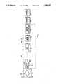
- FIG. 1is an unscaled diagrammatic illustration of the flow path of a test liquid containing residue through an apparatus for measuring impurity concentrations in a liquid according to the principles of the present invention
- FIG. 2is a block diagram illustrating functional elements of the pressure sensitive flow controller of the present invention
- FIG. 3is a graph illustrating the impurity detection efficiency of the present invention utilizing a condensation nucleus counter with a variable number of diffusion screens;
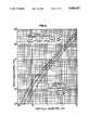
- FIG. 4is a graph illustrating the effect of using a variable number of diffusion screens in conjunction with a condensation nucleus counter in order to achieve varying calibration ranges;
- FIG. 5is a schematic diagram of an optional electrostatic aerosol detector labeled block 80 in FIG. 1;
- FIG. 6is a graph illustrating the charge levels of particles as a function of particle diameter
- FIG. 7is a graph illustrating the sensitivity of an electrical aerosol detector as a function of particle size
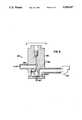
- FIG. 8is a schematic diagram of an optional corona precipitator labeled block 180 in FIG. 1;
- FIG. 9is a preferred embodiment atomizer labeled block 32 in FIG. 1.
- This inventionprovides a test fluid delivery system for automatically insuring that a controlled flowrate is delivered to the atomizer.
- the systemis also preferably arranged and configured so as to provide the test fluid to the measurement device to allow for real time measurements.
- the inventionis described in semiconductor fabrication applications, such application is typical of only one of innumerable types of applications in which the principles of the present invention can be employed. Further, although described with respect to ultrapure water, the present invention is similarly not limited.
- nonvolatile residue in ultrapure liquidscan be measured by use of atomization, evaporation, and measurement and/or counting of the residue particles.
- An apparatus and method for measuring nonvolatile residueis disclosed in U.S. Pat. No. 4,794,086 to Kasper et al.
- Kasper et alliquid is led to a chamber where a vibrating orifice aerosol generator produces uniform droplets. The droplets are generated by controlling the break-up of the liquid. As the droplets are formed, they are introduced into an air jet which enters a chamber. The air jet acts to disperse the droplets and prevent coagulation. At this point, a larger volume of clean, dry air is added to the chamber to aid in the evaporation of liquid.
- the liquidAs the droplets pass through the chamber, the liquid is evaporated to produce residue particles which are drawn into a tube and directed to a particle size analyzer.
- a particle size analyzerused is a light scattering particle spectrometer where the particles pass through incident light causing the light to scatter. The scattered light is detected by a collection optics system. The information from the optic system is then passed to a read out device.
- a CNC devicecan be used as a measuring means to detect the number of fine particles in the aerosol produced.
- Fine particlesenter the CNC and pass through a cloud of vapor produced by heating a liquid such as butyl alcohol.
- Fine particlesin this case nonvolatile residue particles, act as sites upon which vapor can condense.
- Each individual residue particleeffectively increases in size by virtue of the condensing vapor, until they are large enough to be counted by a conventional optical particle counter.
- This counterconsists of a laser light source and focusing lenses.
- the aerosolflowing perpendicularly, confronts the laser light and the particles of the aerosol scatter the laser light. Collecting lenses collect the scattered light at a photoelectric transducer which converts the light intensity to an electric signal.
- the signal of the photoelectric transduceris applied to a counter of the CNC.
- the countercounts the number of pulses from the photoelectric transducer and the counted data is transferred to a signal processing unit where the nonvolatile residue of the ultrapure water is measured based on the original size distribution of the droplet size of the atomizer, a limit of measurement of the particle size at the CNC, and the counted value of the counter unit.
- a CNC devicemay be used to determine the concentration of nonvolatile residue particles in a liquid.
- an electrostatic aerosol detectormay be used to detect the concentration of nonvolatile residue.
- an electrical aerosol detectoris used as a measuring means to detect the concentration of nonvolatile residue particles in the aerosol produced.
- the electrical aerosol detectorincludes an electrostatic charger of aerosol particles and a charged particle detector. The concentration of the nonvolatile residue particles is determined based on the charge measured. A charge is placed on the particles and the current on the charged particles is detected. The number of unipolar elementary charges applied to any particle is determined by the size of the particle.
- discussion of the electrical aerosol detectorwill be deferred pending a more thorough discussion of the flow rate control means, atomizing and drying of the particles, drainage and diffusion filters.
- FIG. 1a possible configuration of an apparatus 10 for measuring residue in a test liquid is shown in the block flow diagram of FIG. 1.
- Ultrapure liquidis fed to the above described measuring devices. The flowrate must be accurate and constant to produce accurate results.
- a fitting 14is cooperatively connected to a liquid supply line 12 in the preferred embodiment.
- a control valve 15is connected to supply line 12 to better control the pressure at which the fluid enters the system.
- the supply line 12is constructed of Teflon® persfluoroalkoxy or "PFA" in the preferred embodiment. It should be understood that other materials which do not introduce contaminants at a permissible level may be used.
- the fitting 14allows transport of the ultrapure liquid via flowrate control means 11, shown in dotted line in FIG. 1, to the measuring apparatus which detects impurities in the liquid. It should be understood that any other suitable means of transport or placement of flow rate control means in fluid communication with the ultrapure liquid (sample liquid) may be used.
- Flow rate control means 11is comprised of several flow restrictive elements, or orifices, and means for placing the sample liquid in fluid communication with the various elements 11a and a control system 11b.
- a first orifice or flow restrictive means 18is located within tubing 16 downstream of fitting 14.
- the first orifice 18is constructed of sapphire and has a diameter of 0.0142 inches.
- the sapphire orifice 18is mounted in a molded PFA housing (not shown) that is secured within a Teflon® PFA fitting 20.
- the first orifice 18is sized and configured to produce a flowrate of approximately 50 milliliters per minute to a second orifice or flow restrictive means 28 in the preferred embodiment.
- PFAis used to provide a noncontaminating wetable surface.
- a second fitting 22is cooperatively connected to tubing 16.
- the second fitting 22includes an inlet, a first outlet 24 and a second outlet 26.
- the second outlet 26allows the ultrapure liquid to flow to the second orifice 28.
- the second orifice 28is sized and configured to allow a flowrate of approximately 0.5 milliliters per minute of the ultrapure liquid in the preferred embodiment.
- the second orifice 28is cooperatively connected to tubing 30 and, in the preferred embodiment, the orifice 28 is constructed of sapphire with a diameter of 0.0028 inches.
- the sapphire orifice 28is mounted in a molded PFA housing (not shown) that is secured with a Teflon® PFA fitting 29.
- the fitting 29may be constructed so as to directly connect as an inlet port of atomizer 32 as next described.
- an atomizer 32is connected to the second orifice 28 such that the outer body of the orifice 28 is a fitting 29 which is operatively connected to the inside of the liquid entry port 34 of the atomizer 32.
- the fitting 29 of the orifice 28screws into the atomizer 32. This arrangement places the liquid supply in fluid communication with atomizer 32.
- the rate of the liquid to the atomizer 32must be accurately controlled to control the size of the droplets formed by the atomizer 32. It is known in the art that by inherent design, an atomizer 32 demands a very low flowrate in order to perform correctly. The liquid flowrate required is approximately 0.5 milliliters per minute in the preferred embodiment. Fluctuations in the rate of liquid feed to the atomizer 32 result in fluctuations in the size range of the droplets produced. Both the variation of droplet size and droplet concentration have a catastrophic effect on the measurement of nonvolatile residue. Those skilled in the art will recognize that although various diameters and flow rates are described herein, such diameters and flow rates are illustrative only and will vary in accordance with the downstream requirements of the atomizer 32 among other design considerations.
- the atomizer 32is made from 316 stainless steel and all wetable parts are electropolished.
- the second orifice 28provides a constant flowrate of approximately 0.5 milliliters per minute (given a fixed appropriate fluid pressure upstream of the second orifice), that required for correct atomization in the preferred embodiment.
- the atomizer 32 in the preferred embodimentis manufactured by TSI, Inc., of St. Paul, Minn., having a model designation Model 3076.
- the flowrate to the atomizer 32is controlled by a feedback system which will next be briefly described. The cooperative interaction between atomizer 32 and the flowrate control system 11b will then follow.
- the flowrate control system 11bbegins at outlet 24 of the second fitting 22. Ultrapure liquid is transported through first orifice 18 to second fitting 22 and through outlet 24 when the liquid passes through tubing 50.
- a pressure transducer or sensor 52is cooperatively connected to tubing 50 and controls the position of a variable restrictive flow element 54 via control circuit 301 and motor 70.
- Variable restrictive flow element 54is preferably a motorized control valve.
- the control system 11bis in communication with a drain at point 56. The ultrapure liquid passing through the pressure sensor 52 and restrictive flow element 54 is discharged to the drain at point 56.
- the atomizer 32is supplied with compressed air or nitrogen to atomize the fluid.
- the gasis supplied by gas supply 37 connected to atomizer 32 and will be described in further detail below.
- the gasis introduced into atomizer 32 at venturi 111 (best seen in FIG. 9). Therefore, atomizer 32 utilizes a venturi effect whereby a negative pressure is created at the liquid entry port 34 to the atomizer 32. In the preferred embodiment, the pressure approximates -1.5 psi at the entry port 34. This considerable negative pressure at the entry port 34 aids in proper fluid flow to the atomizer 32 because the fluid is drawn into the atomizer 32.
- the range of pressures measured by the pressure transducer 52 relative to atmospheric pressureare low and in the preferred embodiment, are in the range of 0.1-0.2 psi. Therefore, if the greater negative pressure created by the venturi effect in the atomizer 32 was not present, day to day variations in atmospheric pressure would affect the fluid flow to the atomizer 32 because the atmospheric pressure would affect the low pressures at the pressure sensor 52. The adjustments made by the flow control system 11 would therefore be affected by atmospheric pressure change so as to reduce the accuracy of the device.
- a positive pressureis provided to the flow system 11 by a second orifice 28.
- This positive pressureallows fluid flow to the control system and drainage of excess water to the drainage system (to be described in further detail below).
- the interaction of these pressures and elementsallows for a constant pressure drop across the second orifice 28 and therefore, the rate of liquid flow to the atomizer 32 remains constant.
- the pressure sensor 52acts as a pressure transducer, the output of which controls the positions of the motorized control valve 54.
- the block diagram of the functional elements of pressure sensor 52is shown in FIG. 2.
- the pressure sensor 52is a flow-through pressure sensing device including a four active element piezoresistive bridge 60. When ultrapure liquid under pressure flows through sensor 52, an output voltage proportional to the pressure is produced.
- pressure sensor 52is manufactured by Honeywell Inc., Microswitch Division of Freeport, Ill. having a model designation of 156PC05 GW.
- An analog to digital (hereinafter referred to as "A/D") converter 62is connected to the piezoresistive bridge 60 via a differential amplifier 64.
- a microprocessor 66is connected to the A/D converter 62.
- a stepper motor controller 68is connected to the microprocessor 66.
- the microprocessoris manufactured by Intel of Santa Clara, Calif. having a model designation 80C31.
- the stepper motor controlleris manufactured by Hurst Manufacturing of Princeton, Ind. having a model designation 3206-001.
- a stepper motor 70is operatively connected to the stepper motor controller 68.
- the control valve 54is cooperatively connected to the shaft of the stepper motor 70.
- Microprocessor 66compares the converted digital signal provided by A/D converter 62 to a predetermined value stored in memory (not shown). Depending on whether the flowrate of the ultra pure water needs to be increased or decreased, a signal is generated by microprocessor 66 and transmitted to the stepper motor controller 68. When the stepper motor 70 receives a signal from the stepper motor controller 68, the stepper motor 70 opens or closes the valve 54 as required to maintain the accurate flowrate. Since the operation of stepper motors and their controllers are well known, they will not be described further herein.
- FIGS. 2, 5 and 8While not specifically detailed in FIGS. 2, 5 and 8 it will be understood that the functional blocks, amplifiers and transducer portions are properly connected to appropriate bias and reference supplies so as to operate in their intended manner. Further, it will be understood that microprocessor 66, A/D convertor 62, and other appropriate functional blocks are connected to appropriate memory, buffer, and other peripheral devices and components so as to operate in their intended manner.
- the pressure sensor 52acts as a pressure tranducer, the output of which controls the position of the motorized control valve 54.
- the ultrapure liquid supply line pressureis dropped across the first orifice 18 and the valve 54.
- the pressure sensor 52measures the ultrapure liquid pressure at fitting 22.
- the pressure sensor 52will detect a fluctuating pressure, and open or close the motorized valve 54 accordingly.
- the pressure of the liquid presented to the second orifice 28will always remain constant and therefore, the flow of the ultrapure liquid through the orifice 28 will also remain constant.
- the physical distance between the second fitting 22 and the atomizer 32is kept as short as possible.
- nonvolatile impurities flowing in the liquid supply line 30are transported within 30 seconds to the atomizer 32 and are subsequently detected by the particle sensor within a fraction of a second.
- the nonvolatile residue monitor 10can then be called a truly on-line system.
- a gas supply 37is connected in fluid communication with atomizer 32.
- the atomizer 32receives the ultrapure liquid and with the compressed air or nitrogen from gas supply 37, atomizes the pure water, and generates a mist.
- the gas supply 37is regulated by pressure regulator 31.
- the gasflows through filter 41 which is connected upstream from atomizer 32 to screen out impurities.
- the filter 41is a pleated glass fiber high efficiency filter in the preferred embodiment.
- the mist created by atomizer 32includes a large number of fine droplets having a predetermined size distribution. Large droplets, that is particles of several microns, impact the walls of the atomizer 32 and drain to the bottom of the atomizer device 32.
- the large droplets, which drain to the bottom of the atomizer 32must be removed from the atomizer 32. Because the system is a real time system with a large volume of water passing through the atomizer 32, adequate drainage is critical. The waste water must be removed continuously in a manner which allows water to drain but does not allow air to enter the atomizer 32 and contaminate the system.
- An outlet 150is formed within the atomizer 32 to allow the water to drain.
- a material 152is sized and configured to fit within the outlet 150 of the atomizer 32. In the preferred embodiment, the material 152 is natural sponge. However, it is to be understood that any other material may be used which meets the necessary specifications of the present invention. The material 152 must be configured to provide an air tight seal, but which allows water to drain out.
- Natural spongeprovides these qualities. Natural sponge swells so that it fills the necessary portion of the atomizer 32 and provides an air tight seal while allowing the water to drip from the outlet 150. The present invention will not tolerate a pressure drop such as a drainage tube at this drainage point and the use of the natural sponge satisfies this requirement.
- a collection means or funnel 154is positioned in cooperation with the atomizer 32 to collect liquid draining from material 152 by means of outlet 150.
- a drain tube 156is connected to collection means or funnel 154.
- a waste outlet 170is connected to tube 156 to dispose of the liquid.
- Drain tube 156is connected to a venturi 158.
- the venturi 158includes an aperture 160 in the interior of the venturi throat, an entrance 162 and an exit 164.
- the waste waterdrains from the material 152 and exits at outlet 150 into a funnel 154 where the water is then guided through drain tube 156.
- Compressed air or nitrogen from gas supply 37is allowed to enter the venturi 158 at entrance 162 through pipe 166 which is regulated by pressure regulator 168.
- the compressed air or nitrogenflows through pipe 166 while being regulated by pressure regulator 168 to a predetermined flow.
- the gasenters the venturi 158 at entrance 162, passes through the venturi 158 and at the venturi throat carries the waste water, which enters at aperture 160, through the exit 164 of the venturi 158.
- the wastethen drains to waste outlet 170 which is connected to a drain system.
- drying airheated filtered compressed air or nitrogen (hereafter referred to as "drying air") from gas supply 37 is forced by means of tubing 141 into the drying column 36 at 40a which evaporates the ultrapure water and leaves the nonvolatile residue particles in drying column 36.
- Pressure regulator 31connected to tubing 141, shown in FIG. 1, regulates the flow of drying air to the drying column 36.
- Fixed orifice 33connected to tubing 141 downstream of pressure regulator 31 further controls the flow of drying air.
- orifice 33is a critical-type orifice. Use of a critical-type orifice allows for flow control without the use of other regulating means.
- Filter 35downstream of orifice 33, filters the drying air so that impurities are not introduced into the system.
- a pleated glass fiber, high efficiency filteris utilized.
- Heater 137is connected to tubing 141 downstream of filter 35. Heater 137 heats the compressed drying air before it flows into drying column 36.
- a sample of nonvolatile residue particlesis drawn into tube 38 at the bottom 40b of the drying column 36.
- the particlesare drawn into tube 38 by an internal pump of a CNC device 47 or a pump of an electrostatic aerosol detector 80 to be described later.
- Outlets 42, at the bottom of column 36,provide a means for exhaust of the particles not taken into the system at 38.
- a diffusion filter 44is cooperatively connected to the tubing 38.
- Tubing 46cooperatively connects a CNC device 47 or electrostatic aerosol detector 80 for calculating the impurity level of the liquid to diffusion filter 44 in two embodiments of the invention.
- the detection sensitivity of a CNC 47can be changed by adding the diffusion filter 44 immediately upstream of the CNC 47, as shown in the preferred embodiment in FIG. 1.
- the diffusion filter 44removes ultrafine particles having sizes below a specified size. Ultrafine particles are impacted onto a fine mesh screen by forces of Brownian motion. Particles larger than the specified size are sufficiently uneffected by Brownian motion and are therefore passed through the diffusion filter 44 to the CNC device 47, while smaller particles are captured by the screen. Multiple screens capture particles with larger predetermined diameters and when placed upstream of a counting device can thus be used to modify the counting efficiency of the device. By this means, the operating range of the nonvolatile residue monitor can be extended.
- a diffusion filter housing 48is utilized and cooperatively connected to tube 38.
- the housing 48can contain several diffusion screens 44.
- the filters or screens 44are made of stainless steel in the preferred embodiment and are of a fine mesh design. By varying the number of screens 44, it is possible to selectively remove particles less than a prescribed size. Only one or two screens 44 are required to provide the nonvolatile residue monitor with a wide operating range.
- the detection efficiencyvaries for a CNC device without a diffusion screen, a CNC with one diffusion screen and a CNC with two diffusion screens.
- the effect which the screen combinations have on the operating range of the nonvolatile residue monitor 10 utilizing a CNC device 47is shown in FIG. 4.
- FIG. 4illustrates the direct relationship between the CNC count and the ultrapure liquid nonvolatile residue in parts per billion. Qualitatively measuring the nonvolatile residue count with the CNC and simultaneously measuring the quantitative nonvolatile residue count by the residue is described in U.S. Pat. No. 4,794,086 to Kasper et al. In effect, the Kasper technique has been used to quantify the nonvolatile residue monitor 10 without the need for the mathematical analysis together with its inherent assumptions.
- the preferred embodiment of the inventionutilizes an aerosol detector 80 to measure the nonvolatile residue in the ultrapure water in place of a CNC device.
- Tubing 46cooperatively connects an aerosol detector 80 to the diffusion housing filter 48.
- the diffusion housing 48 and screens 44may be utilized with the detector 80 to vary the operating range of this system 10 in a manner analogous to the effect of the screens 44 on a CNC device 47 as described above.
- One possible aerosol detector 80is an Electrical Aerosol Detector (referred to hereinafter as "EAD") comprised of two primary components: (1) an electrostatic charger of aerosol particles 82 and (2) a charged-particle detector 84. The particles are charged and then the charge is measured. The concentration of nonvolatile residue is then determined based on the charge measured.
- EADElectrical Aerosol Detector
- Diffusion chargingtakes place when airborne particles are exposed to airborne unipolar ions.
- discussion of the samewill be deferred pending a more thorough discussion of corona discharge, charger portion 82 and electrometer 84.
- FIG. 5illustrates one possible design for an aerosol particle charger 82.
- the charger 82sometimes called a diffusion charger, is in the form of two concentric metal cylinders 86, 88 with a fine (25-mm diameter in the preferred embodiment) tungsten wire 90 connected to cylinder 86 and located along the axis of the cylinders 86, 88.
- Inner cylinder 86includes a corona discharge region 108.
- An annular space 94separates the two cylinders 86, 88.
- the inner cylinder 86has a screen opening 92 for current flow and a screen 106 to prevent particles from being drawn into the cylinder 86.
- the EAD 80includes a top inlet 100 to annular space 94 and an exit 104.
- An upper cone 102is also included and connected to inner cylinder 86 to aid in fluid flow.
- the EADalso includes inlets 103 and 105 for sheath air which may be introduced into the apparatus.
- a positive high voltage on the wire 90produces a corona discharge. It is known in the art that charge density tends to be relatively high on sharp points. The electric field at points above a charged surface is proportional to the charge density so that the electric field may reach high values near sharp points. A corona discharge is produced if the conducting object has a high potential and is surrounded by air. The positively charged conductor attracts negative ions from the surrounding air. If the electric field at a sharp point is great enough, the ions will be accelerated and will collide with air molecules. This produces a great number of additional ions and, therefore, the air is made more conducting.
- the positive ions produced by the corona dischargemigrate toward the inner cylinder 86 where they either deposit on the inner surface of the cylinder 86 or flow radially through the screen opening 92 on the inner cylinder 86.
- the ionsmigrate radially through an annular space 94 toward the outer cylinder wall 96.
- the inner cylinder 86carries a positive voltage relative to the electrically-grounded outer cylinder 88. The level of the voltage on the inner cylinder 86 regulates the current flow through the screen opening 92.
- the ionscollide with the axially-flowing aerosol particles, resulting in the electrostatic charging of the particles.
- a downstream pump 98draws aerosol into the charger portion of the EAD 80.
- the top inlet 100introduces aerosol particles into the charger 82.
- An upper cone 102uniformly distributes the aerosol into the annular space 94 surrounding the inner cylinder 86 of the charger 82 as shown by the arrows in FIG. 5.
- the inlet 100has negligible impaction loss of particles up to 5 ⁇ m.
- the aerosolflows through the annular space 94 between the inner cylinder 86 and the outer cylinder 88 in a laminar fashion due to the design of the EAD 80. While the aerosol moves through the annular space 94, the radially-moving ions charge the particles.
- the charged aerosolcontinues to flow in space 94, finally exiting the charger portion of the EAD 80 at exit 104.
- the aerosolmay be surrounded by two streams of particle-free sheath air.
- the inner sheath airwhich is introduced at sheath air inlet 103 by standard industry equipment (not shown), flows adjacent to the inner-cylinder screen 106. This air flow prevents the aerosol particles from being drawn into the corona discharge region 108 inside the inner cylinder 86. If particles enter the corona discharge region 108, they acquire a higher electrical charge, resulting in a broad charge distribution on the particles and unacceptably high deposition of particles on the cylinder walls.
- outer sheath airintroduced at outer sheath inlet 105 by standard methods and equipment (not shown), displaces the aerosol stream away from the outer cylinder 88.
- the introduction of outer sheath airprevents charged particles from precipitating onto the walls of the outer cylinder 88.
- Both the introduction of the inner and outer sheath air streamsalso provide a more uniform velocity profile for the aerosol flow in the charging region, resulting in more uniform charge on particles of a given size.
- the number of unipolar elementary charges applied to any particleis determined by the size of the particle (d p ), its exposure time to the airborne unipolar ions (t), and the unipolar ion concentration (n). For any given particle size, the number of unipolar elementary charges it will acquire is a function of the mathematical product of (n) and (t).
- FIG. 6shows the charge levels as a function of particle diameter for three values of (nt).
- FIG. 6illustrates that larger particles carry a larger charge than small particles for a given (nt) value.
- the charged nonvolatile fine residue aerosol particlescarry about 10 times more current than when the mean diameter is 0.01 ⁇ m. This is true because the concentration of nonvolatile fine residue aerosol particles is constant regardless of the nonvolatile residue concentration in the ultrapure liquid. For size distributions with constant shape and constant concentration, the fraction of ultrafine particles detected by an electrostatic aerosol detector depends on the mean diameter of the distribution.
- the second portion of the EAD 80is an electrostatic charge detector 84, also called an aerosol electrometer.
- the aerosol electrometerdetects the current on the charged particles.
- the electrical current, I icarried by particles within a narrow size range with particle concentration, N i , and carrying n i elementary charges each, is expressed by the equation:
- the aerosol electrometer 84includes a high-efficiency particle filter 110 having an inlet 116 within an electrically conductive housing 112 that connects to the input of a high-sensitivity operational amplifier (not shown).
- a high-sensitivity operational amplifiernot shown.
- the EAD 80operates by charging the particles in the aerosol in charger section 82 and detecting the particles in electrometer 84.
- the aerosol containing the charged particlesexits the charger 80 and enters the filter 110 at inlet 116, particles deposit on the filter 110 surfaces.
- the electrostatic charges on the particles"drain off" the particles and the filter 110, passing into the inlet of the operational amplifier.
- the filter 110may be made of an electrical insulator in the preferred embodiment. Because like-polarity charges repel each other, a current is created on an electrically conductive path to the operational amplifier. The amplifier then converts the low current levels into a voltage that is detectable by ordinary means.
- the lower detection limit of the nonvolatile residue measuring instrumentis directly proportional to the minimum electrical current detectable by the aerosol electrometer 84.
- Existing aerosol electrometersare capable of detecting charged aerosol currents of 2 ⁇ 10 -16 amperes. As calculated from experimental data shown in FIG. 7, as disclosed by B. Y. H. Liu and K. W. Lee in "An Aerosol Generator of High Stability," American Industrial Hygiene Association Journal, 36(12): 861-865 (1975), this corresponds to a particle concentration of 200 particles per cubic centimeter for 0.01- ⁇ m particles or 10 particles per cubic centimeter for 0.1- ⁇ m particles.
- FIG. 7illustrates the sensitivity of the EAD as a function of residue particle size.
- the dried nonvolatile residue aerosol mean diameterwill be 10 nanometers.
- Much of the particle distributionis detectable by an EAD. For example, if ultrapure liquids have a nonvolatile residue concentration of ppbv (parts per billion by volume) and the atomizer 32 produces droplets with mean diameters of about 1 ⁇ m, the dried nonvolatile residue aerosol mean diameter will be 1 nanometer. Only a small portion of the large-particle tail of the distribution will be detectable by the EAD 80. Reduced sensitivity to smaller particles makes it possible for the EAD 80 to be used to measure the concentration of nonvolatile residue in ultrapure liquids.
- a corona precipitatormay be optionally utilized to collect the residue.
- the corona precipitator 180(best seen in FIGS. 1 and 8) is cooperatively connected to the drying column 36 at exhaust outlets 42 described above.
- the corona precipitator 180comprises a block 182 having a chamber 184 and a microscope stub or substrate 187 including surface 190 connected to the block 182.
- the corona precipitatorfurther includes means to create a corona precipitation region 185 and a precipitator needle 191 connected to and positioned within the precipitation region 185.
- a vacuum pump 193is connected to the corona precipitator 180.
- the block 182is constructed of TEFLON® in the preferred embodiment, an excellent electrical insulator.
- the chamber 184 of the corona precipitator 180is configured as small as possible.
- the depth of the chamber 184is configured to allow time for the particles to become charged and precipitate onto an electron microscope stub or substrate 187, but small enough to maintain a stable corona current with reasonable voltages. It is known in the art that creation of a corona precipitation region 185 at a high voltage power allows operation at a constant corona current. It is important to carefully control power to the precipitator needle 191, thus ensuring a constant corona current. A constant corona current ensures a constant particle collection efficiency.
- the vacuum pump 193draws the residue through the corona precipitator 180.
- the combination of flowing air provided to the system by vacuum pump 193 and the electric field generated by the precipitator needle 191carries the nonvolatile residue particles to the surface 190 of the electron microscope substrate 187.
- the high adhesive forces created between the particles and the surface 190causes the particles to stick firmly to the surface.
- the electron microscope substrate 187may be removed and placed within an electron microscope. By this means, the particles may be identified by elemental comparison and the cause of the contamination in the ultrapure water may be analyzed.
- the electron microscopeIn order to identify the elemental composition of the nonvolatile residue deposited on the surface of the substrate 187, the electron microscope must be equipped with an energy dispersible analysis system. When the electron beam strikes the nonvolatile residue particles, characteristic x-rays are emitted. The energy dispersive x-ray analysis system can characterize this x-ray emission and report elemental composition. Through this elemental analysis, the potential cause of the nonvolatile residue contamination in the ultrapure water may be identified. An analysis of this nature is useful in locating the contamination source within the ultrapure water production system, such that corrective measures can be quickly taken to eliminate the source of the contamination.
Landscapes
- Chemical & Material Sciences (AREA)
- Dispersion Chemistry (AREA)
- Physics & Mathematics (AREA)
- Health & Medical Sciences (AREA)
- Life Sciences & Earth Sciences (AREA)
- Analytical Chemistry (AREA)
- Biochemistry (AREA)
- General Health & Medical Sciences (AREA)
- General Physics & Mathematics (AREA)
- Immunology (AREA)
- Pathology (AREA)
- Sampling And Sample Adjustment (AREA)
Abstract
Description
I.sub.i =qeN.sub.i n.sub.i
Claims (19)
Priority Applications (1)
| Application Number | Priority Date | Filing Date | Title |
|---|---|---|---|
| US07/390,282US5098657A (en) | 1989-08-07 | 1989-08-07 | Apparatus for measuring impurity concentrations in a liquid |
Applications Claiming Priority (1)
| Application Number | Priority Date | Filing Date | Title |
|---|---|---|---|
| US07/390,282US5098657A (en) | 1989-08-07 | 1989-08-07 | Apparatus for measuring impurity concentrations in a liquid |
Publications (1)
| Publication Number | Publication Date |
|---|---|
| US5098657Atrue US5098657A (en) | 1992-03-24 |
Family
ID=23541845
Family Applications (1)
| Application Number | Title | Priority Date | Filing Date |
|---|---|---|---|
| US07/390,282Expired - LifetimeUS5098657A (en) | 1989-08-07 | 1989-08-07 | Apparatus for measuring impurity concentrations in a liquid |
Country Status (1)
| Country | Link |
|---|---|
| US (1) | US5098657A (en) |
Cited By (64)
| Publication number | Priority date | Publication date | Assignee | Title |
|---|---|---|---|---|
| US5156814A (en)* | 1988-07-22 | 1992-10-20 | University Of Manchester Institute Of Science & Technology | Flow injection analysis |
| WO1993005379A1 (en)* | 1991-09-05 | 1993-03-18 | Amherst Process Instruments, Inc. | Non-volatile residue system for monitoring impurities in a liquid |
| US5298967A (en)* | 1992-06-02 | 1994-03-29 | Pacific Scientific Company | Measurement of concentrations of dissolved solvent |
| US5351523A (en)* | 1993-01-21 | 1994-10-04 | Tsi Incorporated | Apparatus and process for determining filter efficiency in removing colloidal suspensions |
| US5374396A (en)* | 1992-05-05 | 1994-12-20 | Tsi Incorporated | Syringe injection system for measuring non-volatile residue in solvents |
| US5969236A (en)* | 1996-08-20 | 1999-10-19 | Ngk Insulators, Ltd. | Particle sensor |
| WO1999062607A1 (en)* | 1998-06-04 | 1999-12-09 | Advanced Cardiovascular Systems, Inc. | Method and apparatus for concentrating a solute in solution with a solvent |
| US6023138A (en)* | 1997-09-11 | 2000-02-08 | International Business Machines Corporation | Fan venturi blockage detection |
| WO2000078447A1 (en)* | 1999-06-18 | 2000-12-28 | Tsi Incorporated | Aerosol charge adjusting apparatus employing a corona discharge |
| US6230572B1 (en) | 1998-02-13 | 2001-05-15 | Tsi Incorporated | Instrument for measuring and classifying nanometer aerosols |
| US6248590B1 (en) | 1998-02-27 | 2001-06-19 | Cytomation, Inc. | Method and apparatus for flow cytometry |
| US6290820B1 (en)* | 1997-12-17 | 2001-09-18 | Iowa State University Research Foundation, Inc. | Apparatus and method for concentrating a dilute solution |
| US6330060B1 (en)* | 1997-10-10 | 2001-12-11 | California Institute Of Technology | Cloud condensation nucleus spectrometer |
| US20020096123A1 (en)* | 1997-12-31 | 2002-07-25 | Colorado State University, Colorado State University Research Foundation | Integrated herd management system utilizing isolated populations of X-chromosome bearing and Y-chromosome bearing spermatozoa |
| US20020119558A1 (en)* | 1997-12-31 | 2002-08-29 | Xy, Inc. | Multiple sexed embryo production system for mammals using low numbers of spermatozoa |
| WO2002075279A1 (en) | 2001-03-15 | 2002-09-26 | Tsi Incorporated | Evaporative electrical detector |
| US20030129091A1 (en)* | 1997-12-31 | 2003-07-10 | Colorado State University Through Its Agent, Colorado State University Research Foundation | Collection systems for cytometer sorting of sperm |
| US6620620B1 (en) | 1998-04-27 | 2003-09-16 | Era Systems, Inc. | Micro liquid evaporator |
| US20030211009A1 (en)* | 2001-05-18 | 2003-11-13 | Buchanan Kris S. | Rapid multi-material sample input system |
| US20040031071A1 (en)* | 2000-10-05 | 2004-02-12 | Xy, Inc. | System of hysteroscopic insemination of mares |
| US20040055030A1 (en)* | 2002-09-13 | 2004-03-18 | Xy, Inc. | Sperm cell processing and preservation systems |
| US20040053243A1 (en)* | 2000-05-09 | 2004-03-18 | Evans Kenneth M. | High purity x-chromosome bearing and y-chromosome bearing populations of spermatozoa |
| US6819411B1 (en) | 1997-01-31 | 2004-11-16 | Xy, Inc. | Optical apparatus |
| US20050112541A1 (en)* | 2003-03-28 | 2005-05-26 | Monsanto Technology Llc | Apparatus, methods and processes for sorting particles and for providing sex-sorted animal sperm |
| US7012689B2 (en) | 2001-05-17 | 2006-03-14 | Dako Colorado, Inc. | Flow cytometer with active automated optical alignment system |
| US7024316B1 (en) | 1999-10-21 | 2006-04-04 | Dakocytomation Colorado, Inc. | Transiently dynamic flow cytometer analysis system |
| US20060141628A1 (en)* | 2002-08-15 | 2006-06-29 | Xy, Inc. | High resolution flow cytometer |
| US7094527B2 (en) | 2000-11-29 | 2006-08-22 | Xy, Inc. | System for in-vitro fertilization with spermatozoa separated into X-chromosome and Y-chromosome bearing populations |
| US20060238744A1 (en)* | 2003-02-25 | 2006-10-26 | O'donohue Stephen J | Apparatus |
| US20070026378A1 (en)* | 2005-07-29 | 2007-02-01 | Xy, Inc. | Methods and apparatus for reducing protein content in sperm cell extenders |
| US7208265B1 (en) | 1999-11-24 | 2007-04-24 | Xy, Inc. | Method of cryopreserving selected sperm cells |
| WO2008058179A3 (en)* | 2006-11-07 | 2008-06-19 | Fluid Measurement Technologies | System for measuring non-volatile residue in ultra pure water |
| US20080212094A1 (en)* | 2003-09-25 | 2008-09-04 | Deka Products Limited Partnership | Detection system and method for aerosol delivery |
| WO2009074910A1 (en)* | 2007-12-12 | 2009-06-18 | Koninklijke Philips Electronics N.V. | Device for characterizing a size distribution of electrically-charged airborne particles in an air flow |
| US20090183554A1 (en)* | 2008-01-22 | 2009-07-23 | Grant Donald C | Particle concentration measurement technology |
| US7573573B1 (en)* | 2005-05-13 | 2009-08-11 | Yufa Aleksandr L | Method and particle measuring and counting apparatus with selectable channels of a specimen flow |
| US20090287421A1 (en)* | 2004-07-27 | 2009-11-19 | George C Malachowski | Enhancing Flow Cytometry Discrimination with Geometric Transformation |
| WO2009099243A3 (en)* | 2008-02-05 | 2010-04-29 | Panasonic Corporation | Method for collecting gaseous sample |
| US7713687B2 (en) | 2000-11-29 | 2010-05-11 | Xy, Inc. | System to separate frozen-thawed spermatozoa into x-chromosome bearing and y-chromosome bearing populations |
| US7723116B2 (en) | 2003-05-15 | 2010-05-25 | Xy, Inc. | Apparatus, methods and processes for sorting particles and for providing sex-sorted animal sperm |
| US7772005B1 (en) | 1998-07-30 | 2010-08-10 | Xy, Llc | Method of establishing an equine artificial insemination sample |
| WO2010096425A1 (en)* | 2009-02-18 | 2010-08-26 | Battelle Memorial Institute | Small area electrostatic aerosol collector |
| US20100271053A1 (en)* | 2009-04-24 | 2010-10-28 | Beckman Coulter, Inc. | Method of Characterizing Particles |
| US7833147B2 (en) | 2004-07-22 | 2010-11-16 | Inguran, LLC. | Process for enriching a population of sperm cells |
| US7838210B2 (en) | 2004-03-29 | 2010-11-23 | Inguran, LLC. | Sperm suspensions for sorting into X or Y chromosome-bearing enriched populations |
| US20110078803A1 (en)* | 2002-08-01 | 2011-03-31 | Xy, Llc | Sex selected equine embryo production system |
| US20110145777A1 (en)* | 2009-12-15 | 2011-06-16 | Sundar Iyer | Intelligent memory system compiler |
| US20110214489A1 (en)* | 2008-01-22 | 2011-09-08 | Grant Donald C | Residue concentration measurement technology |
| WO2011133516A1 (en)* | 2010-04-19 | 2011-10-27 | Battelle Memorial Institute | Electrohydrodynamic spraying |
| US8486618B2 (en) | 2002-08-01 | 2013-07-16 | Xy, Llc | Heterogeneous inseminate system |
| EP1980837A4 (en)* | 2006-02-01 | 2014-11-26 | Rion Co | particle measuring device |
| US20150108244A1 (en)* | 2013-10-18 | 2015-04-23 | Bissell Homecare, Inc. | Apparatus for cleaning a surface |
| US20150316470A1 (en)* | 2012-12-27 | 2015-11-05 | Centre National De La Recherche Scientifique | Method and device for characterising a fluid medium using a photoelectric transducer |
| US20150330886A1 (en)* | 2014-05-16 | 2015-11-19 | Industrial Technology Research Institute | Apparatus and method for mixing solution and system and method for monitoring particles in solution |
| WO2017017183A1 (en)* | 2015-07-28 | 2017-02-02 | Commissariat A L'energie Atomique Et Aux Energies Alternatives | Device for collecting particles contained in an aerosol, comprising electrometres to determine nanoparticle concentration and particle size |
| US9579662B2 (en) | 2010-08-27 | 2017-02-28 | Aerosol Dynamics Inc. | Condensation-evaporator nanoparticle charger |
| US9610531B2 (en) | 2010-08-27 | 2017-04-04 | Aerosol Dynamics Inc. | Wick wetting for water condensation systems |
| US9851333B2 (en) | 2013-05-29 | 2017-12-26 | Dionex Corporation | Nebulizer for charged aerosol detection (CAD) system |
| US10429366B2 (en) | 2014-05-28 | 2019-10-01 | Dionex Corporation | Methods and systems for detection of non-volatile solutes |
| US11029240B2 (en) | 2018-10-12 | 2021-06-08 | Aerosol Dynamics Inc. | Wick moisture sensor for airborne particle condensational growth systems |
| US11237091B2 (en) | 2018-11-01 | 2022-02-01 | Aerosol Dynamics Inc. | Humidity conditioning for water-based condensational growth of ultrafine particles |
| WO2022235318A1 (en)* | 2021-05-07 | 2022-11-10 | Tsi Incorporated | Aerosol-based liquid particle detection measurement |
| US11686660B2 (en) | 2018-06-07 | 2023-06-27 | Sensors, Inc. | Particle concentration analyzing system and method |
| CN116337816A (en)* | 2023-03-22 | 2023-06-27 | 华电电力科学研究院有限公司 | An online monitoring device and monitoring method for sulfur trioxide in flue gas |
Citations (13)
| Publication number | Priority date | Publication date | Assignee | Title |
|---|---|---|---|---|
| US3476729A (en)* | 1964-02-17 | 1969-11-04 | Phillips Petroleum Co | Polymerization process control and apparatus therefor |
| US3765771A (en)* | 1971-10-27 | 1973-10-16 | Coulter Electronics | Liquid borne particle sensing method using aerosolizing techniques |
| US3854321A (en)* | 1973-04-27 | 1974-12-17 | B Dahneke | Aerosol beam device and method |
| US3984296A (en)* | 1974-09-13 | 1976-10-05 | Richards John R | System and process for controlling air pollution |
| US4173415A (en)* | 1976-08-20 | 1979-11-06 | Science Spectrum, Inc. | Apparatus and process for rapidly characterizing and differentiating large organic cells |
| US4284496A (en)* | 1979-12-10 | 1981-08-18 | Newton William A | Particle guiding apparatus and method |
| US4361400A (en)* | 1980-11-26 | 1982-11-30 | The United States Of America As Represented By The United States Department Of Energy | Fluidic assembly for an ultra-high-speed chromosome flow sorter |
| US4449816A (en)* | 1981-05-11 | 1984-05-22 | Nitta Gelatin Kabushiki Kaisha | Method for measuring the number of hyperfine particles and a measuring system therefor |
| US4519983A (en)* | 1979-12-28 | 1985-05-28 | Institut Francais Du Petrole | Method and device for determining the organic carbon content of a sample |
| US4585169A (en)* | 1982-06-02 | 1986-04-29 | Dunham-Bush, Inc. | Constant volume flow burner fuel control system |
| US4761074A (en)* | 1986-03-24 | 1988-08-02 | Nihon Kagaku Kogyo Co., Ltd. | Method for measuring impurity concentrations in a liquid and an apparatus therefor |
| US4794086A (en)* | 1985-11-25 | 1988-12-27 | Liquid Air Corporation | Method for measurement of impurities in liquids |
| US4853618A (en)* | 1986-03-14 | 1989-08-01 | Holley John E F | Particle counter with variable sized aperture |
- 1989
- 1989-08-07USUS07/390,282patent/US5098657A/ennot_activeExpired - Lifetime
Patent Citations (13)
| Publication number | Priority date | Publication date | Assignee | Title |
|---|---|---|---|---|
| US3476729A (en)* | 1964-02-17 | 1969-11-04 | Phillips Petroleum Co | Polymerization process control and apparatus therefor |
| US3765771A (en)* | 1971-10-27 | 1973-10-16 | Coulter Electronics | Liquid borne particle sensing method using aerosolizing techniques |
| US3854321A (en)* | 1973-04-27 | 1974-12-17 | B Dahneke | Aerosol beam device and method |
| US3984296A (en)* | 1974-09-13 | 1976-10-05 | Richards John R | System and process for controlling air pollution |
| US4173415A (en)* | 1976-08-20 | 1979-11-06 | Science Spectrum, Inc. | Apparatus and process for rapidly characterizing and differentiating large organic cells |
| US4284496A (en)* | 1979-12-10 | 1981-08-18 | Newton William A | Particle guiding apparatus and method |
| US4519983A (en)* | 1979-12-28 | 1985-05-28 | Institut Francais Du Petrole | Method and device for determining the organic carbon content of a sample |
| US4361400A (en)* | 1980-11-26 | 1982-11-30 | The United States Of America As Represented By The United States Department Of Energy | Fluidic assembly for an ultra-high-speed chromosome flow sorter |
| US4449816A (en)* | 1981-05-11 | 1984-05-22 | Nitta Gelatin Kabushiki Kaisha | Method for measuring the number of hyperfine particles and a measuring system therefor |
| US4585169A (en)* | 1982-06-02 | 1986-04-29 | Dunham-Bush, Inc. | Constant volume flow burner fuel control system |
| US4794086A (en)* | 1985-11-25 | 1988-12-27 | Liquid Air Corporation | Method for measurement of impurities in liquids |
| US4853618A (en)* | 1986-03-14 | 1989-08-01 | Holley John E F | Particle counter with variable sized aperture |
| US4761074A (en)* | 1986-03-24 | 1988-08-02 | Nihon Kagaku Kogyo Co., Ltd. | Method for measuring impurity concentrations in a liquid and an apparatus therefor |
Non-Patent Citations (38)
| Title |
|---|
| "A New Method for Measuring Nonvolatile Residue for Ultrapure Solvents", David B. Blackford et al., The Journal of Environmental Sciences, Jul./Aug. 1987, pp. 43-47. |
| "Aerosol Generation Method for Measuring Particles Suspended in Water-Detection of Particulate Impurities in Ultrapure Water and Sizing of Fine Powders-", Niida et al., dated 11 Jan. 1988. |
| "Aerosol Technology in Hazard Evaluation", Mercer, American Industrial Hygien Association and U.S. Atomic Energy Commission, Production of Test Aerosols 9, pp. 336-367. |
| "Analysis of High Purity Chemicals: Examination and Improvement of the Residue after Evaporation Test for Solvents", Campbell et al., Analytical Chemistry, vol. 50, No. 7, Jun. 1978, pp. 963-964. |
| "Book of SEMI Standards 1985", Semiconductor Equipment and Materials Institute, Incorporated, vol. 1, Chemicals Division, 1985. |
| "Cleanliness Meter and its Application to Solvent Cleaning", Marsh, Fifth Annual Technical Meeting and Exhibit, Houston, Texas, Mar. 29-Apr. 1, 1966. |
| "Development of a Continuous Monitor for Nonvolatile Impurity in Ultrapure Water and Solvents", Sato et al. |
| "Development of a New Continuous Monitor for Nonvolatile Solute in Ultrapure Water by Atomization", The Journal of Environmental Sciences, Kousaka, et al., Jul./Aug., 1987, pp. 39-42. |
| "Development on an On-Line Method for Gauging the Total Weight of Foreign Materials in IC Pure Water", Takahasi et al., Automated Integrated Circuits Manufacturing, Proceeding of the 4th Symposium, Chicago 1988, Proceedings of the Electrochemical Society, pp. 155-162. |
| "Highpure Monitor", Nomura Micro Science, Pamphlet. |
| "Laboratory Generation of Particulates With Emphasis on Submicron Aerosols", Benjamin Y. H. Liu, Journal of the Air Pollution Control Association, vol. 24, No. 12, pp. 1170-1172, Dec. 1974. |
| "Particle Characterization", David B. Blackford and Gary R. Simons, dated 22 Sep. 1986. |
| "Standard Test Method for Nonvolatile Matter in Volatile Solvents for Use in Paint, Varnish, Lacquer, and Related Products", American Society for Testing and Materials, D 1353, pp. 1-2. |
| "Submicron Aerosol Characterization of Water by a Differential Mobility Particle Sizer", Kournikakis et al., J. Aerosol Sci., vol. 19, No. 7, pp. 1425-1428, 1988. |
| "Ultrapure Water Management in Semiconductor Factories Using a Total Evaporation Residue Meter", Tada et al., Journal of Electronics Materials, pp. 107-113, Jun. 1988. |
| A New Method for Measuring Nonvolatile Residue for Ultrapure Solvents , David B. Blackford et al., The Journal of Environmental Sciences, Jul./Aug. 1987, pp. 43 47.* |
| Aerosol Generation Method for Measuring Particles Suspended in Water Detection of Particulate Impurities in Ultrapure Water and Sizing of Fine Powders , Niida et al., dated 11 Jan. 1988.* |
| Aerosol Technology in Hazard Evaluation , Mercer, American Industrial Hygien Association and U.S. Atomic Energy Commission, Production of Test Aerosols 9, pp. 336 367.* |
| Analysis of High Purity Chemicals: Examination and Improvement of the Residue after Evaporation Test for Solvents , Campbell et al., Analytical Chemistry, vol. 50, No. 7, Jun. 1978, pp. 963 964.* |
| Blackford, D. B. et al., "A New Method for Measuring Nonvolatile Residue for Ultrapure solvents", J. of Environ. Sci. 30(4) 43-47, 1987. |
| Blackford, D. B. et al., A New Method for Measuring Nonvolatile Residue for Ultrapure solvents , J. of Environ. Sci. 30(4) 43 47, 1987.* |
| Book of SEMI Standards 1985 , Semiconductor Equipment and Materials Institute, Incorporated, vol. 1, Chemicals Division, 1985.* |
| Cleanliness Meter and its Application to Solvent Cleaning , Marsh, Fifth Annual Technical Meeting and Exhibit, Houston, Texas, Mar. 29 Apr. 1, 1966.* |
| Development of a Continuous Monitor for Nonvolatile Impurity in Ultrapure Water and Solvents , Sato et al.* |
| Development of a New Continuous Monitor for Nonvolatile Solute in Ultrapure Water by Atomization , The Journal of Environmental Sciences, Kousaka, et al., Jul./Aug., 1987, pp. 39 42.* |
| Development on an On Line Method for Gauging the Total Weight of Foreign Materials in IC Pure Water , Takahasi et al., Automated Integrated Circuits Manufacturing, Proceeding of the 4th Symposium, Chicago 1988, Proceedings of the Electrochemical Society, pp. 155 162.* |
| Highpure Monitor , Nomura Micro Science, Pamphlet.* |
| Industrial Test News, TSI Incorporated, vol. 2, Issue 1, p. 4, "Model 8110 Automated Filter Tester". |
| Industrial Test News, TSI Incorporated, vol. 2, Issue 1, p. 4, Model 8110 Automated Filter Tester .* |
| Laboratory Generation of Particulates With Emphasis on Submicron Aerosols , Benjamin Y. H. Liu, Journal of the Air Pollution Control Association, vol. 24, No. 12, pp. 1170 1172, Dec. 1974.* |
| Particle Characterization , David B. Blackford and Gary R. Simons, dated 22 Sep. 1986.* |
| Perry & Green, "Chemical Engineers Handbook", 6 ed. 1984, Chapter 22-26. |
| Perry & Green, Chemical Engineers Handbook , 6 ed. 1984, Chapter 22 26.* |
| Standard Test Method for Nonvolatile Matter in Volatile Solvents for Use in Paint, Varnish, Lacquer, and Related Products , American Society for Testing and Materials, D 1353, pp. 1 2.* |
| Submicron Aerosol Characterization of Water by a Differential Mobility Particle Sizer , Kournikakis et al., J. Aerosol Sci., vol. 19, No. 7, pp. 1425 1428, 1988.* |
| TSI Journal of Particle Instrumentation, vol. 3, No. 1, pp. 3 9, Jan. Jun. 1988, Generation and Maintenance of Process Gases with Extremely Low Particle Levels , Donald C. Grant.* |
| TSI Journal of Particle Instrumentation, vol. 3, No. 1, pp. 3-9, Jan.-Jun. 1988, "Generation and Maintenance of Process Gases with Extremely Low Particle Levels", Donald C. Grant. |
| Ultrapure Water Management in Semiconductor Factories Using a Total Evaporation Residue Meter , Tada et al., Journal of Electronics Materials, pp. 107 113, Jun. 1988.* |
Cited By (151)
| Publication number | Priority date | Publication date | Assignee | Title |
|---|---|---|---|---|
| US5156814A (en)* | 1988-07-22 | 1992-10-20 | University Of Manchester Institute Of Science & Technology | Flow injection analysis |
| WO1993005379A1 (en)* | 1991-09-05 | 1993-03-18 | Amherst Process Instruments, Inc. | Non-volatile residue system for monitoring impurities in a liquid |
| US5278626A (en)* | 1991-09-05 | 1994-01-11 | Amherst Process Instruments, Inc. | Non-volatile residue system for monitoring impurities in a liquid |
| US5374396A (en)* | 1992-05-05 | 1994-12-20 | Tsi Incorporated | Syringe injection system for measuring non-volatile residue in solvents |
| US5298967A (en)* | 1992-06-02 | 1994-03-29 | Pacific Scientific Company | Measurement of concentrations of dissolved solvent |
| US5351523A (en)* | 1993-01-21 | 1994-10-04 | Tsi Incorporated | Apparatus and process for determining filter efficiency in removing colloidal suspensions |
| US5969236A (en)* | 1996-08-20 | 1999-10-19 | Ngk Insulators, Ltd. | Particle sensor |
| US20050110996A1 (en)* | 1997-01-31 | 2005-05-26 | Sharpe Jonathan C. | Optical apparatus |
| US7929137B2 (en) | 1997-01-31 | 2011-04-19 | Xy, Llc | Optical apparatus |
| US7586604B2 (en) | 1997-01-31 | 2009-09-08 | Xy, Inc. | Optical apparatus |
| US6819411B1 (en) | 1997-01-31 | 2004-11-16 | Xy, Inc. | Optical apparatus |
| US7221453B2 (en) | 1997-01-31 | 2007-05-22 | Xy, Inc. | Optical apparatus |
| US6023138A (en)* | 1997-09-11 | 2000-02-08 | International Business Machines Corporation | Fan venturi blockage detection |
| US6330060B1 (en)* | 1997-10-10 | 2001-12-11 | California Institute Of Technology | Cloud condensation nucleus spectrometer |
| US6529272B2 (en)* | 1997-10-10 | 2003-03-04 | California Institute Of Technology | Techniques for characterizing cloud condensation nuclel |
| US6290820B1 (en)* | 1997-12-17 | 2001-09-18 | Iowa State University Research Foundation, Inc. | Apparatus and method for concentrating a dilute solution |
| US20020119558A1 (en)* | 1997-12-31 | 2002-08-29 | Xy, Inc. | Multiple sexed embryo production system for mammals using low numbers of spermatozoa |
| US7195920B2 (en) | 1997-12-31 | 2007-03-27 | Xy, Inc. | Collection systems for cytometer sorting of sperm |
| US20020096123A1 (en)* | 1997-12-31 | 2002-07-25 | Colorado State University, Colorado State University Research Foundation | Integrated herd management system utilizing isolated populations of X-chromosome bearing and Y-chromosome bearing spermatozoa |
| US9422523B2 (en) | 1997-12-31 | 2016-08-23 | Xy, Llc | System and method for sorting cells |
| US20070026379A1 (en)* | 1997-12-31 | 2007-02-01 | Colorado State University Through Its Agent, Colorado State University Research Foundation | Collection Systems for Cytometer Sorting of Sperm |
| US9365822B2 (en) | 1997-12-31 | 2016-06-14 | Xy, Llc | System and method for sorting cells |
| US20070099260A1 (en)* | 1997-12-31 | 2007-05-03 | Xy, Inc. | Use of a Composition which Regulates Oxidation/Reduction Reactions Intracellularly and/or Extracellularly in a Staining or Sorting Process |
| US20030129091A1 (en)* | 1997-12-31 | 2003-07-10 | Colorado State University Through Its Agent, Colorado State University Research Foundation | Collection systems for cytometer sorting of sperm |
| US7629113B2 (en) | 1997-12-31 | 2009-12-08 | Xy, Inc | Multiple sexed embryo production system for bovine mammals |
| US6230572B1 (en) | 1998-02-13 | 2001-05-15 | Tsi Incorporated | Instrument for measuring and classifying nanometer aerosols |
| US6248590B1 (en) | 1998-02-27 | 2001-06-19 | Cytomation, Inc. | Method and apparatus for flow cytometry |
| US6589792B1 (en) | 1998-02-27 | 2003-07-08 | Dakocytomation Denmark A/S | Method and apparatus for flow cytometry |
| US6620620B1 (en) | 1998-04-27 | 2003-09-16 | Era Systems, Inc. | Micro liquid evaporator |
| WO1999062607A1 (en)* | 1998-06-04 | 1999-12-09 | Advanced Cardiovascular Systems, Inc. | Method and apparatus for concentrating a solute in solution with a solvent |
| US6461572B1 (en) | 1998-06-04 | 2002-10-08 | Advanced Cardiovascular Systems, Inc. | Method and apparatus for concentrating a solute in solution with a solvent |
| US6391149B1 (en) | 1998-06-04 | 2002-05-21 | Advanced Cardiovascular Systems, Inc. | Method and apparatus for concentrating a solute in solution with a solvent |
| US7772005B1 (en) | 1998-07-30 | 2010-08-10 | Xy, Llc | Method of establishing an equine artificial insemination sample |
| US6544484B1 (en) | 1999-06-18 | 2003-04-08 | Tsi Incorporated | Aerosol charge adjusting apparatus employing a corona discharge |
| WO2000078447A1 (en)* | 1999-06-18 | 2000-12-28 | Tsi Incorporated | Aerosol charge adjusting apparatus employing a corona discharge |
| US7024316B1 (en) | 1999-10-21 | 2006-04-04 | Dakocytomation Colorado, Inc. | Transiently dynamic flow cytometer analysis system |
| US20060259253A1 (en)* | 1999-10-21 | 2006-11-16 | Dako Colorado, Inc. | Systems for transiently dynamic flow cytometer analysis |
| US20070099171A1 (en)* | 1999-11-24 | 2007-05-03 | Xy, Inc. | Sperm Suspensions for Sorting Into X or Y Chromosome-bearing Enriched Populations |
| US20070092860A1 (en)* | 1999-11-24 | 2007-04-26 | Xy, Inc. | Sperm Suspensions For Use in Insemination |
| US7208265B1 (en) | 1999-11-24 | 2007-04-24 | Xy, Inc. | Method of cryopreserving selected sperm cells |
| US7820425B2 (en) | 1999-11-24 | 2010-10-26 | Xy, Llc | Method of cryopreserving selected sperm cells |
| US10208345B2 (en) | 2000-05-09 | 2019-02-19 | Xy, Llc | Method for producing high purity X-chromosome bearing and Y-chromosome bearing populations of spermatozoa |
| US7371517B2 (en) | 2000-05-09 | 2008-05-13 | Xy, Inc. | High purity X-chromosome bearing and Y-chromosome bearing populations of spermatozoa |
| US9145590B2 (en) | 2000-05-09 | 2015-09-29 | Xy, Llc | Methods and apparatus for high purity X-chromosome bearing and Y-chromosome bearing populations of spermatozoa |
| US20040053243A1 (en)* | 2000-05-09 | 2004-03-18 | Evans Kenneth M. | High purity x-chromosome bearing and y-chromosome bearing populations of spermatozoa |
| US20080233635A1 (en)* | 2000-05-09 | 2008-09-25 | Xy, Inc. | Methods and Apparatus for High Purity X-Chromosome Bearing and Y-Chromosome Bearing Populations Of Spermatozoa |
| US20040031071A1 (en)* | 2000-10-05 | 2004-02-12 | Xy, Inc. | System of hysteroscopic insemination of mares |
| US8137967B2 (en) | 2000-11-29 | 2012-03-20 | Xy, Llc | In-vitro fertilization systems with spermatozoa separated into X-chromosome and Y-chromosome bearing populations |
| US7094527B2 (en) | 2000-11-29 | 2006-08-22 | Xy, Inc. | System for in-vitro fertilization with spermatozoa separated into X-chromosome and Y-chromosome bearing populations |
| US9879221B2 (en) | 2000-11-29 | 2018-01-30 | Xy, Llc | Method of in-vitro fertilization with spermatozoa separated into X-chromosome and Y-chromosome bearing populations |
| US7771921B2 (en) | 2000-11-29 | 2010-08-10 | Xy, Llc | Separation systems of frozen-thawed spermatozoa into X-chromosome bearing and Y-chromosome bearing populations |
| US20060281176A1 (en)* | 2000-11-29 | 2006-12-14 | Xy, Inc. | In-Vitro fertilization systems with spermatozoa separated into X-chromosome and Y-chromosome bearing populations |
| US7713687B2 (en) | 2000-11-29 | 2010-05-11 | Xy, Inc. | System to separate frozen-thawed spermatozoa into x-chromosome bearing and y-chromosome bearing populations |
| US8652769B2 (en) | 2000-11-29 | 2014-02-18 | Xy, Llc | Methods for separating frozen-thawed spermatozoa into X-chromosome bearing and Y-chromosome bearing populations |
| EP1379851A4 (en)* | 2001-03-15 | 2005-08-10 | Tsi Inc | Evaporative electrical detector |
| WO2002075279A1 (en) | 2001-03-15 | 2002-09-26 | Tsi Incorporated | Evaporative electrical detector |
| US6568245B2 (en) | 2001-03-15 | 2003-05-27 | Tsi Incorporated | Evaporative electrical detector |
| US7012689B2 (en) | 2001-05-17 | 2006-03-14 | Dako Colorado, Inc. | Flow cytometer with active automated optical alignment system |
| US20030211009A1 (en)* | 2001-05-18 | 2003-11-13 | Buchanan Kris S. | Rapid multi-material sample input system |
| US8486618B2 (en) | 2002-08-01 | 2013-07-16 | Xy, Llc | Heterogeneous inseminate system |
| US8211629B2 (en) | 2002-08-01 | 2012-07-03 | Xy, Llc | Low pressure sperm cell separation system |
| US8497063B2 (en) | 2002-08-01 | 2013-07-30 | Xy, Llc | Sex selected equine embryo production system |
| US20110078803A1 (en)* | 2002-08-01 | 2011-03-31 | Xy, Llc | Sex selected equine embryo production system |
| US20060141628A1 (en)* | 2002-08-15 | 2006-06-29 | Xy, Inc. | High resolution flow cytometer |
| US7855078B2 (en) | 2002-08-15 | 2010-12-21 | Xy, Llc | High resolution flow cytometer |
| US20040055030A1 (en)* | 2002-09-13 | 2004-03-18 | Xy, Inc. | Sperm cell processing and preservation systems |
| US11230695B2 (en) | 2002-09-13 | 2022-01-25 | Xy, Llc | Sperm cell processing and preservation systems |
| US7169548B2 (en) | 2002-09-13 | 2007-01-30 | Xy, Inc. | Sperm cell processing and preservation systems |
| US11261424B2 (en) | 2002-09-13 | 2022-03-01 | Xy, Llc | Sperm cell processing systems |
| US7561268B2 (en) | 2003-02-25 | 2009-07-14 | Polymer Laboratories Ltd | Evaporative light scattering detector |
| US20060238744A1 (en)* | 2003-02-25 | 2006-10-26 | O'donohue Stephen J | Apparatus |
| US7799569B2 (en) | 2003-03-28 | 2010-09-21 | Inguran, Llc | Process for evaluating staining conditions of cells for sorting |
| US8748183B2 (en) | 2003-03-28 | 2014-06-10 | Inguran, Llc | Method and apparatus for calibrating a flow cytometer |
| US11718826B2 (en) | 2003-03-28 | 2023-08-08 | Inguran, Llc | System and method for sorting particles |
| US7758811B2 (en) | 2003-03-28 | 2010-07-20 | Inguran, Llc | System for analyzing particles using multiple flow cytometry units |
| US9377390B2 (en) | 2003-03-28 | 2016-06-28 | Inguran, Llc | Apparatus, methods and processes for sorting particles and for providing sex-sorted animal sperm |
| US20050112541A1 (en)* | 2003-03-28 | 2005-05-26 | Monsanto Technology Llc | Apparatus, methods and processes for sorting particles and for providing sex-sorted animal sperm |
| US7943384B2 (en) | 2003-03-28 | 2011-05-17 | Inguran Llc | Apparatus and methods for sorting particles |
| US8709817B2 (en) | 2003-03-28 | 2014-04-29 | Inguran, Llc | Systems and methods for sorting particles |
| US8664006B2 (en) | 2003-03-28 | 2014-03-04 | Inguran, Llc | Flow cytometer apparatus and method |
| US9040304B2 (en) | 2003-03-28 | 2015-05-26 | Inguran, Llc | Multi-channel system and methods for sorting particles |
| US11104880B2 (en) | 2003-03-28 | 2021-08-31 | Inguran, Llc | Photo-damage system for sorting particles |
| US10100278B2 (en) | 2003-03-28 | 2018-10-16 | Inguran, Llc | Multi-channel system and methods for sorting particles |
| US8709825B2 (en) | 2003-03-28 | 2014-04-29 | Inguran, Llc | Flow cytometer method and apparatus |
| US7723116B2 (en) | 2003-05-15 | 2010-05-25 | Xy, Inc. | Apparatus, methods and processes for sorting particles and for providing sex-sorted animal sperm |
| US20110079220A1 (en)* | 2003-09-25 | 2011-04-07 | Deka Products Limited Partnership | Detection System and Method for Aerosol Delivery |
| US20080212094A1 (en)* | 2003-09-25 | 2008-09-04 | Deka Products Limited Partnership | Detection system and method for aerosol delivery |
| US20090213373A1 (en)* | 2003-09-25 | 2009-08-27 | Deka Products Limited Partnership | Detection System and Method for Aerosol Delivery |
| US8687191B2 (en) | 2003-09-25 | 2014-04-01 | Deka Products Limited Partnership | Detection system and method for aerosol delivery |
| US7548314B2 (en)* | 2003-09-25 | 2009-06-16 | Deka Products Limited Partnership | Detection system and method for aerosol delivery |
| US7838210B2 (en) | 2004-03-29 | 2010-11-23 | Inguran, LLC. | Sperm suspensions for sorting into X or Y chromosome-bearing enriched populations |
| US7892725B2 (en) | 2004-03-29 | 2011-02-22 | Inguran, Llc | Process for storing a sperm dispersion |
| US7833147B2 (en) | 2004-07-22 | 2010-11-16 | Inguran, LLC. | Process for enriching a population of sperm cells |
| US20090287421A1 (en)* | 2004-07-27 | 2009-11-19 | George C Malachowski | Enhancing Flow Cytometry Discrimination with Geometric Transformation |
| US9134220B2 (en) | 2004-07-27 | 2015-09-15 | Beckman Coulter, Inc. | Enhancing flow cytometry discrimination with geometric transformation |
| USRE46559E1 (en) | 2004-07-27 | 2017-09-26 | Beckman Coulter, Inc. | Enhancing flow cytometry discrimination with geometric transformation |
| US11408813B2 (en) | 2004-07-27 | 2022-08-09 | Beckman Coulter, Inc. | Enhancing flow cytometry discrimination with geometric transformation |
| US7573573B1 (en)* | 2005-05-13 | 2009-08-11 | Yufa Aleksandr L | Method and particle measuring and counting apparatus with selectable channels of a specimen flow |
| US7618770B2 (en) | 2005-07-29 | 2009-11-17 | Xy, Inc. | Methods and apparatus for reducing protein content in sperm cell extenders |
| US20070026378A1 (en)* | 2005-07-29 | 2007-02-01 | Xy, Inc. | Methods and apparatus for reducing protein content in sperm cell extenders |
| EP1980837A4 (en)* | 2006-02-01 | 2014-11-26 | Rion Co | particle measuring device |
| US20080144003A1 (en)* | 2006-11-07 | 2008-06-19 | Blackford David B | System for Measuring Non-Volatile Residue in Ultra Pure Water |
| WO2008058179A3 (en)* | 2006-11-07 | 2008-06-19 | Fluid Measurement Technologies | System for measuring non-volatile residue in ultra pure water |
| KR100971608B1 (en) | 2006-11-07 | 2010-07-20 | 플루이드 메져먼트 테크놀로지스, 아이엔씨. | System for Measuring Non-volatile Residues in Ultrapure Water |
| US7777868B2 (en) | 2006-11-07 | 2010-08-17 | Fluid Measurement Technologies, Inc. | System for measuring non-volatile residue in ultra pure water |
| WO2009074910A1 (en)* | 2007-12-12 | 2009-06-18 | Koninklijke Philips Electronics N.V. | Device for characterizing a size distribution of electrically-charged airborne particles in an air flow |
| CN101896807B (en)* | 2007-12-12 | 2014-04-23 | 皇家飞利浦电子股份有限公司 | Apparatus for Characterizing the Size Distribution of Charged Dust Particles in Air Streams |
| US20100282006A1 (en)* | 2007-12-12 | 2010-11-11 | Koninklijke Philips Electronics N.V. | Device for characterizing a size distribution of electrically-charged airborne particles in an air flow |
| US8627732B2 (en) | 2007-12-12 | 2014-01-14 | Koninklijke Philips N.V. | Device for characterizing a size distribution of electrically-charged airborne particles in an air flow |
| US9086350B2 (en) | 2008-01-22 | 2015-07-21 | Ct Associates, Inc. | Particle concentration measurement technology |
| US20090183554A1 (en)* | 2008-01-22 | 2009-07-23 | Grant Donald C | Particle concentration measurement technology |
| US8272253B2 (en)* | 2008-01-22 | 2012-09-25 | Ct Associates, Inc. | Particle concentration measurement technology |
| US8573034B2 (en)* | 2008-01-22 | 2013-11-05 | Ct Associates, Inc. | Residue concentration measurement technology |
| US20110214489A1 (en)* | 2008-01-22 | 2011-09-08 | Grant Donald C | Residue concentration measurement technology |
| US9513198B2 (en) | 2008-01-22 | 2016-12-06 | Ct Associates, Inc. | Residue concentration measurement technology |
| CN101932923B (en)* | 2008-02-05 | 2012-06-27 | 松下电器产业株式会社 | Method for collecting gaseous sample |
| WO2009099243A3 (en)* | 2008-02-05 | 2010-04-29 | Panasonic Corporation | Method for collecting gaseous sample |
| US20100116068A1 (en)* | 2008-02-05 | 2010-05-13 | Panasonic Corporation | Method for collecting gaseous sample |
| US7866220B2 (en) | 2008-02-05 | 2011-01-11 | Panasonic Corporation | Method for collecting gaseous sample |
| JP2011501802A (en)* | 2008-02-05 | 2011-01-13 | パナソニック株式会社 | Sample gas collection method |
| WO2010096425A1 (en)* | 2009-02-18 | 2010-08-26 | Battelle Memorial Institute | Small area electrostatic aerosol collector |
| US8398746B2 (en) | 2009-02-18 | 2013-03-19 | Battelle Memorial Institute | Small area electrostatic aerosol collector |
| US20100271053A1 (en)* | 2009-04-24 | 2010-10-28 | Beckman Coulter, Inc. | Method of Characterizing Particles |
| US8395398B2 (en)* | 2009-04-24 | 2013-03-12 | Beckman Coulter, Inc. | Method of characterizing particles |
| US20110145777A1 (en)* | 2009-12-15 | 2011-06-16 | Sundar Iyer | Intelligent memory system compiler |
| WO2011133516A1 (en)* | 2010-04-19 | 2011-10-27 | Battelle Memorial Institute | Electrohydrodynamic spraying |
| US9200987B2 (en)* | 2010-04-19 | 2015-12-01 | Battelle Memorial Institute | Electrohydrodynamic spraying |
| US10207276B2 (en) | 2010-04-19 | 2019-02-19 | Battelle Memorial Institute | Electrohydrodynamic spraying |
| US20130032031A1 (en)* | 2010-04-19 | 2013-02-07 | Battelle Memorial Institute | Electrohydrodynamic spraying |
| US9579662B2 (en) | 2010-08-27 | 2017-02-28 | Aerosol Dynamics Inc. | Condensation-evaporator nanoparticle charger |
| US9610531B2 (en) | 2010-08-27 | 2017-04-04 | Aerosol Dynamics Inc. | Wick wetting for water condensation systems |
| US20150316470A1 (en)* | 2012-12-27 | 2015-11-05 | Centre National De La Recherche Scientifique | Method and device for characterising a fluid medium using a photoelectric transducer |
| US9726598B2 (en)* | 2012-12-27 | 2017-08-08 | Centre National De La Recherche Scientifique | Method and device for characterising a fluid medium using a photoelectric transducer |
| US9851333B2 (en) | 2013-05-29 | 2017-12-26 | Dionex Corporation | Nebulizer for charged aerosol detection (CAD) system |
| US11137379B2 (en) | 2013-05-29 | 2021-10-05 | Dionex Corporation | Nebulizer for charged aerosol detection (CAD) system |
| US10821459B2 (en)* | 2013-10-18 | 2020-11-03 | Bissell Inc. | Apparatus for cleaning a surface |
| US20150108244A1 (en)* | 2013-10-18 | 2015-04-23 | Bissell Homecare, Inc. | Apparatus for cleaning a surface |
| US9625365B2 (en)* | 2014-05-16 | 2017-04-18 | Industrial Technology Research Institute | System and method for monitoring particles in solution |
| US20150330886A1 (en)* | 2014-05-16 | 2015-11-19 | Industrial Technology Research Institute | Apparatus and method for mixing solution and system and method for monitoring particles in solution |
| US10429366B2 (en) | 2014-05-28 | 2019-10-01 | Dionex Corporation | Methods and systems for detection of non-volatile solutes |
| FR3039434A1 (en)* | 2015-07-28 | 2017-02-03 | Commissariat Energie Atomique | DEVICE FOR COLLECTING PARTICLES CONTAINED IN AEROSOL WITH ELECTROMETERS FOR DETERMINING THE CONCENTRATION AND GRANULOMETRY OF NANOPARTICLES |
| CN107921443A (en)* | 2015-07-28 | 2018-04-17 | 原子能和替代能源委员会 | Device particles contained in aerosol is collected including the electronic device for measuring concentrations of nanoparticles and grain graininess |
| CN107921443B (en)* | 2015-07-28 | 2020-03-20 | 原子能和替代能源委员会 | Aerosol particle collecting device with nano particle concentration and particle size measuring device |
| WO2017017183A1 (en)* | 2015-07-28 | 2017-02-02 | Commissariat A L'energie Atomique Et Aux Energies Alternatives | Device for collecting particles contained in an aerosol, comprising electrometres to determine nanoparticle concentration and particle size |
| US10675639B2 (en) | 2015-07-28 | 2020-06-09 | Commissariat A L'energie Atomique Et Aux Energies Alternatives | Device for collecting particles contained in an aerosol, comprising electrometres to determine nanoparticle concentration and particle size |
| US11686660B2 (en) | 2018-06-07 | 2023-06-27 | Sensors, Inc. | Particle concentration analyzing system and method |
| US11029240B2 (en) | 2018-10-12 | 2021-06-08 | Aerosol Dynamics Inc. | Wick moisture sensor for airborne particle condensational growth systems |
| US11237091B2 (en) | 2018-11-01 | 2022-02-01 | Aerosol Dynamics Inc. | Humidity conditioning for water-based condensational growth of ultrafine particles |
| WO2022235318A1 (en)* | 2021-05-07 | 2022-11-10 | Tsi Incorporated | Aerosol-based liquid particle detection measurement |
| US11933708B2 (en) | 2021-05-07 | 2024-03-19 | Tsi Incorporated | Aerosol-based liquid particle detection measurement |
| CN116337816A (en)* | 2023-03-22 | 2023-06-27 | 华电电力科学研究院有限公司 | An online monitoring device and monitoring method for sulfur trioxide in flue gas |
Similar Documents
| Publication | Publication Date | Title |
|---|---|---|
| US5098657A (en) | Apparatus for measuring impurity concentrations in a liquid | |
| US6639671B1 (en) | Wide-range particle counter | |
| US4761074A (en) | Method for measuring impurity concentrations in a liquid and an apparatus therefor | |
| US6607597B2 (en) | Method and apparatus for deposition of particles on surfaces | |
| US9086350B2 (en) | Particle concentration measurement technology | |
| US7605910B2 (en) | Particle measuring system and method | |
| US4794086A (en) | Method for measurement of impurities in liquids | |
| US5026155A (en) | Process for sizing particles using condensation nucleus counting | |
| US7437908B2 (en) | Particle counter | |
| US6923848B2 (en) | Collecting apparatus of floating dusts in atmosphere | |
| US20080137065A1 (en) | Measuring Analyte Concentrations in Liquids | |
| US5278626A (en) | Non-volatile residue system for monitoring impurities in a liquid | |
| US3413545A (en) | Apparatus and method for determining aerosol particle concentration and particle size distribution | |
| Kawaguchi et al. | Investigation of airborne particles by inductively coupled plasma emission spectrometry calibrated with monodisperse aerosols | |
| US6892142B2 (en) | Method of analyzing particles suspended in liquid and liquid-suspended particle analyzer for carrying out the method | |
| US4375673A (en) | Charge spectrograph | |
| Chen et al. | Design and testing of an aerosol/sheath inlet for high resolution measurements with a DMA | |
| Liu et al. | Intercomparison of different “absolute” instruments for measurement of aerosol number concentration | |
| JP4180952B2 (en) | Wide range particle counter | |
| Blackford et al. | Particle size analysis of carbon black | |
| US3765771A (en) | Liquid borne particle sensing method using aerosolizing techniques | |
| JP2012037318A (en) | Apparatus and method for measuring particle in liquid | |
| KR102623388B1 (en) | Liquid particle couner and liquid particle monitoring system with the same | |
| Niida et al. | Aerosol Generation Method for Measuring Particles Suspended in Water–Detection of Particulate Impurities in Ultrapure Water and Sizing of Fine Powders– | |
| Zhao | Laboratory measurements of the response of optical particle counters to particles of different shape and refractive index |
Legal Events
| Date | Code | Title | Description |
|---|---|---|---|
| AS | Assignment | Owner name:TSI INCORPORATED, A CORP. OF MN, MINNESOTA Free format text:ASSIGNMENT OF ASSIGNORS INTEREST.;ASSIGNORS:BLACKFORD, DAVID B.;QUANT, FREDERIC R.;KERRICK, THOMAS A.;AND OTHERS;REEL/FRAME:005158/0222 Effective date:19890926 | |
| STCF | Information on status: patent grant | Free format text:PATENTED CASE | |
| FEPP | Fee payment procedure | Free format text:PAYOR NUMBER ASSIGNED (ORIGINAL EVENT CODE: ASPN); ENTITY STATUS OF PATENT OWNER: LARGE ENTITY | |
| FEPP | Fee payment procedure | Free format text:PAYER NUMBER DE-ASSIGNED (ORIGINAL EVENT CODE: RMPN); ENTITY STATUS OF PATENT OWNER: LARGE ENTITY | |
| FPAY | Fee payment | Year of fee payment:4 | |
| FEPP | Fee payment procedure | Free format text:PAT HLDR NO LONGER CLAIMS SMALL ENT STAT AS INDIV INVENTOR (ORIGINAL EVENT CODE: LSM1); ENTITY STATUS OF PATENT OWNER: LARGE ENTITY | |
| FPAY | Fee payment | Year of fee payment:8 | |
| AS | Assignment | Owner name:U.S. BANK NATIONAL ASSOCIATION, MINNESOTA Free format text:SECURITY INTEREST;ASSIGNOR:TSI INCORPORATED;REEL/FRAME:010909/0205 Effective date:20000503 | |
| FPAY | Fee payment | Year of fee payment:12 |