US5098426A - Method and apparatus for precision laser surgery - Google Patents
Method and apparatus for precision laser surgeryDownload PDFInfo
- Publication number
- US5098426A US5098426AUS07/307,315US30731589AUS5098426AUS 5098426 AUS5098426 AUS 5098426AUS 30731589 AUS30731589 AUS 30731589AUS 5098426 AUS5098426 AUS 5098426A
- Authority
- US
- United States
- Prior art keywords
- laser
- tissue
- tracking
- surgeon
- surgical
- Prior art date
- Legal status (The legal status is an assumption and is not a legal conclusion. Google has not performed a legal analysis and makes no representation as to the accuracy of the status listed.)
- Expired - Lifetime
Links
Images


Classifications
- A—HUMAN NECESSITIES
- A61—MEDICAL OR VETERINARY SCIENCE; HYGIENE
- A61F—FILTERS IMPLANTABLE INTO BLOOD VESSELS; PROSTHESES; DEVICES PROVIDING PATENCY TO, OR PREVENTING COLLAPSING OF, TUBULAR STRUCTURES OF THE BODY, e.g. STENTS; ORTHOPAEDIC, NURSING OR CONTRACEPTIVE DEVICES; FOMENTATION; TREATMENT OR PROTECTION OF EYES OR EARS; BANDAGES, DRESSINGS OR ABSORBENT PADS; FIRST-AID KITS
- A61F9/00—Methods or devices for treatment of the eyes; Devices for putting in contact-lenses; Devices to correct squinting; Apparatus to guide the blind; Protective devices for the eyes, carried on the body or in the hand
- A61F9/007—Methods or devices for eye surgery
- A61F9/008—Methods or devices for eye surgery using laser
- A—HUMAN NECESSITIES
- A61—MEDICAL OR VETERINARY SCIENCE; HYGIENE
- A61B—DIAGNOSIS; SURGERY; IDENTIFICATION
- A61B17/00—Surgical instruments, devices or methods
- A61B17/32—Surgical cutting instruments
- A—HUMAN NECESSITIES
- A61—MEDICAL OR VETERINARY SCIENCE; HYGIENE
- A61B—DIAGNOSIS; SURGERY; IDENTIFICATION
- A61B17/00—Surgical instruments, devices or methods
- A61B2017/00017—Electrical control of surgical instruments
- A61B2017/00199—Electrical control of surgical instruments with a console, e.g. a control panel with a display
- A—HUMAN NECESSITIES
- A61—MEDICAL OR VETERINARY SCIENCE; HYGIENE
- A61B—DIAGNOSIS; SURGERY; IDENTIFICATION
- A61B17/00—Surgical instruments, devices or methods
- A61B2017/00681—Aspects not otherwise provided for
- A61B2017/00694—Aspects not otherwise provided for with means correcting for movement of or for synchronisation with the body
- A—HUMAN NECESSITIES
- A61—MEDICAL OR VETERINARY SCIENCE; HYGIENE
- A61B—DIAGNOSIS; SURGERY; IDENTIFICATION
- A61B17/00—Surgical instruments, devices or methods
- A61B2017/00973—Surgical instruments, devices or methods pedal-operated
- A—HUMAN NECESSITIES
- A61—MEDICAL OR VETERINARY SCIENCE; HYGIENE
- A61F—FILTERS IMPLANTABLE INTO BLOOD VESSELS; PROSTHESES; DEVICES PROVIDING PATENCY TO, OR PREVENTING COLLAPSING OF, TUBULAR STRUCTURES OF THE BODY, e.g. STENTS; ORTHOPAEDIC, NURSING OR CONTRACEPTIVE DEVICES; FOMENTATION; TREATMENT OR PROTECTION OF EYES OR EARS; BANDAGES, DRESSINGS OR ABSORBENT PADS; FIRST-AID KITS
- A61F9/00—Methods or devices for treatment of the eyes; Devices for putting in contact-lenses; Devices to correct squinting; Apparatus to guide the blind; Protective devices for the eyes, carried on the body or in the hand
- A61F2009/0035—Devices for immobilising a patient's head with respect to the instrument
- A—HUMAN NECESSITIES
- A61—MEDICAL OR VETERINARY SCIENCE; HYGIENE
- A61F—FILTERS IMPLANTABLE INTO BLOOD VESSELS; PROSTHESES; DEVICES PROVIDING PATENCY TO, OR PREVENTING COLLAPSING OF, TUBULAR STRUCTURES OF THE BODY, e.g. STENTS; ORTHOPAEDIC, NURSING OR CONTRACEPTIVE DEVICES; FOMENTATION; TREATMENT OR PROTECTION OF EYES OR EARS; BANDAGES, DRESSINGS OR ABSORBENT PADS; FIRST-AID KITS
- A61F9/00—Methods or devices for treatment of the eyes; Devices for putting in contact-lenses; Devices to correct squinting; Apparatus to guide the blind; Protective devices for the eyes, carried on the body or in the hand
- A61F9/007—Methods or devices for eye surgery
- A61F9/008—Methods or devices for eye surgery using laser
- A61F2009/00844—Feedback systems
- A61F2009/00846—Eyetracking
- A—HUMAN NECESSITIES
- A61—MEDICAL OR VETERINARY SCIENCE; HYGIENE
- A61F—FILTERS IMPLANTABLE INTO BLOOD VESSELS; PROSTHESES; DEVICES PROVIDING PATENCY TO, OR PREVENTING COLLAPSING OF, TUBULAR STRUCTURES OF THE BODY, e.g. STENTS; ORTHOPAEDIC, NURSING OR CONTRACEPTIVE DEVICES; FOMENTATION; TREATMENT OR PROTECTION OF EYES OR EARS; BANDAGES, DRESSINGS OR ABSORBENT PADS; FIRST-AID KITS
- A61F9/00—Methods or devices for treatment of the eyes; Devices for putting in contact-lenses; Devices to correct squinting; Apparatus to guide the blind; Protective devices for the eyes, carried on the body or in the hand
- A61F9/007—Methods or devices for eye surgery
- A61F9/008—Methods or devices for eye surgery using laser
- A61F2009/00861—Methods or devices for eye surgery using laser adapted for treatment at a particular location
- A61F2009/00872—Cornea
- A—HUMAN NECESSITIES
- A61—MEDICAL OR VETERINARY SCIENCE; HYGIENE
- A61F—FILTERS IMPLANTABLE INTO BLOOD VESSELS; PROSTHESES; DEVICES PROVIDING PATENCY TO, OR PREVENTING COLLAPSING OF, TUBULAR STRUCTURES OF THE BODY, e.g. STENTS; ORTHOPAEDIC, NURSING OR CONTRACEPTIVE DEVICES; FOMENTATION; TREATMENT OR PROTECTION OF EYES OR EARS; BANDAGES, DRESSINGS OR ABSORBENT PADS; FIRST-AID KITS
- A61F9/00—Methods or devices for treatment of the eyes; Devices for putting in contact-lenses; Devices to correct squinting; Apparatus to guide the blind; Protective devices for the eyes, carried on the body or in the hand
- A61F9/007—Methods or devices for eye surgery
- A61F9/008—Methods or devices for eye surgery using laser
- A61F2009/00897—Scanning mechanisms or algorithms
Definitions
- the inventionrelates to surgical methods and apparatus, and in particular the invention is directed to improved methods and apparatus for precision laser surgery.
- the system of the inventionis used for effecting precise laser eye surgery.
- the inventionis applicable to non-surgical diagnostic procedures or non-medical procedures involving precision laser operations, such as industrial processes.
- a laser's energyis composed of light photons
- the wavelength of the laser emissionis composed of light photons
- a lasercan be deemed to perform "non-invasive" surgery, in that the surgeon need not perforate the overlying tissue layers in order to generate an effect at a prescribed depth.
- Non-invasive laser surgerycorresponds to the effort to minimize the laser energy deposition onto the living tissues on the way to and directly behind the targeted tissues along the optical path of the laser beam when compared to the energy deposition at the intended target.
- Dr. Aron-RosaU.S. Pat. No. 4,309,998 introduced a mode locked Nd:YAG laser for use in Ophthalmology which claimed to evidence plasma decay induced generation of outwardly expanding shock waves.
- Dr. FrankhauserU.S. Pat. No. 4,391,275 claimed a somewhat similar result using a Q-switched Nd:YAG laser.
- Ultrashort pulsed lasershave now established themselves as the modality of choice for many surgical procedures where propagating thermal effects are to be suppressed.
- the principal instruments used todayfor example in ophthalmology, for targeting diagnostics and inspection are (1) the surgical microscope, (2) the slit lamp microscope, (3) the keratometer, (4) the pachymeter, (5) the corneoscope, (6) the specular microscope, (7) the A&B ultrasonic scanners, and (8) the fundus camera.
- Items 1, 2, and 8provide the surgeon with an image of his target. Items 3, 4, 5, 6, and 7 provide the surgeon with measurements of specific dimensions of a patient's eye and condition.
- the full information content of a given signalis interpreted so as to provide this supporting diagnostic information, and the resulting accuracy achievable is within a few human cells or better.
- a method, apparatus and system for carefully controlled and precision laser microsurgeryincludes a user interface which gives the physician ample and precise three dimensional visual information as to the topography of the area to be operated upon and as to the aiming location and depth penetration of the surgical laser beam.
- the systemis also useful for non-medical operations, such as industrial operations, wherein a focused laser beam is used to perform operations on an object subject to movement, with a high degree of precision.
- a video screenis provided in front of the surgeon, and the screen may even be divided into four quadrants: one quadrant showing an image of cell walls in real time taken from a video camera based, zooming surgical microscope which may be capable of enlargement from 25 times to 500 times, for example.
- the surgical microscope imagemight show a region having a dimension of as small as the order of 100 microns, for example.
- This real-time video imageis of tissue at the precise location and depth at which the surgical laser is currently directed, or, in the alternative, of critical cells directly posterior to the target which should be monitored to help assure no damage to these sensitive tissues (e.g., corneal endothelial cells posterior to, but along the optical axis of, a laser pulse).
- the surgical microscopemay be used to scan different regions at different depths under the control of the surgeon/user, even though the laser is not yet being fired.
- Two of the other quadrants of the video screenmay be dedicated to computer-generated images showing cross sections through the tissues to be operated upon.
- the cross sectionsmay be taken through two separate and orthogonal planes, or other cross sectional planes may be selected by the surgeon.
- Each computer-generated imagemay have a crossbar or other indicator showing precisely where the surgical laser is currently directed.
- a fourth quadrant of the video screenmay be dedicated to a computer-generated plan view, greatly enlarged but not to the extent of the surgical microscope view.
- this last quadrant, and/or on any of the other cross sectional representationsthere may be superimposed a "template" selected by the physician, for automatically controlling the path of the firing of the laser, to precisely control the size and location of the laser generated lesions to be formed in the course of the microsurgery.
- a templateselected by the physician, for automatically controlling the path of the firing of the laser, to precisely control the size and location of the laser generated lesions to be formed in the course of the microsurgery.
- the surgeonmay draw on a bank of prior experience and knowledge relating to a particular form of microsurgery, such as ophthalmic surgery directed to a particular type of correction.
- the accuracy of the apparatus and system of the inventionpreferably is within 5 microns, as determined by a closed loop system which incorporates actual measurement of the target position within the loop.
- a microstepper motor based assemblymay have a single step resolution of 0.1 micron verified against a motor encoder, but thermal gradients in the slides may yield greater variations.
- position of the slidecan be verified via an independent optical encoder, but the random vibrations of the target can invalidate the relative accuracy of the motor.
- the surgeonhas knowledge of the shape of tissues within the field of view and the precise location of where he is aiming the instrument within those structures, within an accuracy of 5 microns. Such precision was not attainable in a systematic, predictable manner with any of the prior instruments or practices used.
- the present inventionseeks to obviate and improve upon the need for binocular vision used to obtain stereoptic images.
- the instrumentprovides the surgeon/user with the option of selecting any given cross sections of the three dimensional structures to be operated upon, and the contour levels of the structures.
- the focal point of the imaging assembly(precisely the same as the focal point of the focused laser pulse, which is only activated when deliberately fired), is also automatically displayed on each of the display screens. There is no need for a separate aiming beam, because the laser beam trajectory not only shares the same optical path with the imaging system, but both light paths pass coaxially through the same final focussing lens. Misalignment of two different light paths is therefore eliminated, and also eliminated is the necessity to verify whether two different light paths have a common focal plane or common focal point.
- the user of the instrumentOnce the user of the instrument has sufficient cross sectional representations of the structure and contour levels of the tissues to be operated upon, he can then draw onto the computer screen the intended therapeutic procedure.
- a number of different systemscan be used for conveying to the computer the desired procedure. One is to use commercially available touch screens with a special light pencil. Alternatively, a trackball or joy stick can be used. The surgeon can then either draw freehand his proposed operation, or use some preprogrammed geometrical designs.
- Another system, described briefly above,is to superimpose on the patterns being displayed on the screen from the imaging information, a computer generated template of the desired surgical path.
- a library of such templatescan be developed a priori and via accumulating experience, and the ability to modify these templates to fit particular requirements of a given situation is provided to the surgeon/user. This is a very important feature since the operations intended by surgeons are often complicated and delicate.
- the surgeonhas the ability to reflect as to the particular three dimensional shape of the lesion to be generated for that particular patient, for the proposed therapy, prior to commencing the procedure.
- the motion of the patientis stabilized by use of a target acquisition and tracking system which allows the surgeon to predetermine his firing pattern on an image which is automatically stabilized over time.
- a target acquisition and tracking systemwhich allows the surgeon to predetermine his firing pattern on an image which is automatically stabilized over time.
- the only limitations in time with the system of the present inventionrelate to the repetition rate of the laser itself, and the ability of the tracking system to successfully stabilize the image to within the requisite error tolerances for safety and efficacy.
- tracking response rates of several times faster (as determined by safety and stability considerations) than the maximum repetition rate of the laser (and faster than the maximum frame rate of the display means)have been achieved in an embodiment of the invention for following the motion of the target.
- the surgeoncan predetermine a proposed pattern of therapeutic treatment, can compare the pattern to the actual tissues targeted, can reflect on the potential outcome of the procedure, can compare his proposed surgery with what other surgeons have done in similar situations, can compare his proposed course of action with theoretical models of structure relaxations, and can still have the assurance that when he is finally satisfied with the proposed procedure, he can push a button to cause the desired surgery to be carried out at a high rate of independently targeted shots per second, but at a rate less than the response rate of the tracking system and with an added factor of safety. This speed minimizes the risk during surgery of catastrophic patient motion.
- Safetyis a very important consideration with laser surgery.
- some safety shut off procedures for laser firinghave depended upon human reaction time, such as a surgeon's foot pedal for disabling the instrument when a situation arises which would make firing unsafe.
- human reaction timesuch as a surgeon's foot pedal for disabling the instrument when a situation arises which would make firing unsafe.
- some instrumentshave relied as a safety feature on a pressure sensor where the patient's forehead normally rests during surgery. If insufficient pressure were detected by the sensor, the instrument would be disabled from firing.
- the blinking eyeexemplifies the functioning of aspects of the safety features of the present instrument and system.
- the topographic information on which the tracking system has been stabilizing the motions of the moving eyeis significantly altered.
- the systemthen interrupts the preprogrammed firing sequence while maintaining in memory the topography it was previously working on, the template information selected by the surgeon, and the position at which the firing sequence was last executed prior to interrupt for that given template for that determined topography.
- the target acquisition systemcan go back to recognizing the topography it was previously operating in and automatically place the laser focal point at the next position in the prescribed firing sequence.
- the surgeonmay then use a switch to recommence the firing, so as to have time to verify that the target has indeed been recaptured.
- the surgeonmay elect to override the manual switch for restart of the firing sequence so that the system automatically returns to the template prescribed firing sequence, without prompting.
- the tracking subsystem of the inventionserves two important purposes--it tracks and follows in real time (virtually "real time", i.e. delayed only by the speed of the electronics and the tracking mirror) the movements of the patient's tissue, not only the voluntary movements which can be damped with specialized treatment, but also the involuntary movements which are more difficult to control on a living specimen) and continuously re-presents an image of the same section of tissue at a closed loop speed equivalent to real time.
- the surgeon/useris provided a continuous, substantially immobilized view of that tissue regardless of patient movements; and it further provides a fail-safe means for immediately stopping the action of the surgical laser beam in the event the tracking is lost, i.e. the tissue is not recognized by the computer stored image on which the tracking algorithm is following the motion, and the vision is not re-aimed at the appropriate tissue within the selected operating interval.
- the corneoscopeprovides contour levels on the outer surface of the cornea, or corneal epithelial surface, derived from projected concentric illumination rings.
- the keratometergives cross sectional curvatures of the epithelial surface layer resulting in an estimation of the diopter power of the front surface lens of the eye--the corneal epithelium surface. Only one group of points is examined, giving very limited information. Pachymeters are used to determine a center-axis thickness measurement of the cornea.
- the system, apparatus, and method of the present invention for precision laser surgery, particularly ophthalmic surgerytakes an entirely different approach.
- Continuously updated imagespreferably video images
- these imagescontain all information, in three dimensions, needed for the surgeon to reliably and accurately conduct a given ophthalmic surgery procedure.
- Movements of the eyeare followed by a tracking system which operates at least as fast as both the speed with which the video screen retraces video images and, using dedicated microprocessors, at closed loop refresh speeds greater than several times the maximum repetition rate of the laser. Tracking by following the subject eye tissue, i.e.
- this margin of error distanceis held within 5 microns in all situations during ophthalmic surgery, although with future use and experimentation it may be found that either more stringent or alternatively more lax error tolerances are desirable to improve overall performance.
- a tracking mirrorwhich may be under the directional control of a piezoelectric or electromagnetic transducer, or other rapid servo device.
- the transduceradjusts the position of the mirror along two rotational axes at speeds on the target in excess of 30 microns per millisecond, based on microprocessor-provided information relating to the new location of the same tissue.
- an illumination light, the surgical laser beam and an intensified video surgical microscopeare along the same optical axis, on which is also located the turning mirror for tracking the tissue.
- the surgical microscopeprovides a greatly enlarged image of the tissue at which the laser is directed, with a field adjustable from about 0.1 to 100 mm.
- the profiling cameraobtains data from the position of a projected Ronchi ruling on and inside the eye, sufficient to generate the full range of information in three dimensions needed by the surgeon, for presentation on the video screen.
- the profiling cameraalso, in concert with the microprocessor and programming, records the position of certain features and finds and relocates those same features after the eye has moved. This information is also used by the microprocessor and programming to determine Z axis offsets in target position and to generate a command to the Z axis positioning drive to follow such target motions as detected by the profilometer camera. These motions will be analyzed and corrected by the motions of the front element of the objective lens.
- both the analysis of the Z axis offset and the corrective lens motionsare slower than the X,Y analysis and motion of the tracking servo mirrors.
- the same information, microprocessor, and programmingserve as a backup signal to the faster tracking servo mirror signal to be used for periodic verification of accuracy and, more specifically, as an absolute position reference whenever the tracking detectors fail to recognize the target or its location either because of extraneous impediments or because of the unforseen speed of random motions.
- this same information initiating from the profilometer camerawould be used to drive tracking servo mirror to turn the mirror appropriately so that the axis of the tracking camera is again directed toward the same center of view that existed before the movement occurred.
- the tracking cameracan recognize movements relating to changes in depth of a certain tissue feature from the final focussing lens.
- the microprocessor and programmingissue a command to the final focussing lens to adjust the focal point of the system, i.e. of the tracking camera, the surgical microscope, and the surgical laser so that these are again correctly focused at the required tissue feature position.
- the tracking cameraspreferably are linear array detectors that scan only one line of position. They are dedicated detectors which are not only extremely rapid, but since they accumulate less data than the profilometer camera, can be read out in less than 100 microseconds.
- fast tracking loopcan use the linear array detectors, while the slow loop may use the profilometer camera information at the maximum attainable video frame rate.
- the present instrument and systemis of high sensitivity, requiring only low levels of illumination, and produces video images of high contrast and high resolution. Illumination levels are kept well within established safety levels for the human eye. With the optics of the present system the patient's tissue is observed from an appreciable distance, sufficient for comfort to the patient even during eye surgery, and sufficient to permit the surgeon/user ready access to the patient to insure safety, to reassure the patient, for access in case of emergency, or for any other reason which the surgeon/user may feel justifiable.
- Zoom opticsare included so that the physician can select a range of magnification for the video image, which may be from about, say, 25 ⁇ to 500 ⁇ . Different zooming ranges may be appropriate for different types of surgical procedures while maintaining an overall zooming capability of approximately 20 fold.
- the system of the present inventionuses a combination of specular and scattered light techniques for detecting and identifying reflecting surfaces, surface displacements, features, and shapes of the patient's tissue. This is particularly useful in the eye where it can prove difficult to differentiate, using strictly specular techniques, between the amorphous tear layer anterior to the cornea and the structured epithelial surface layer of the cornea. Even the cell walls of the endothelial cells of the cornea will scatter light.
- the intensified surgical microscopecan produce an image of these actual cells by forming an image composed by detecting scattered light.
- the surgical microscope, as well as the tracking camerasubstantially excludes specularly reflecting light by cross polarization. Other methods for damping specular reflections preferentially to scattered images are possible, but not considered as optimal in this embodiment of the invention.
- the instrument and system of the present inventionrepeatedly presents to the surgeon/user the precise focal point of the imaging system and of the surgical laser for reliable control of laser surgery, particularly ophthalmic surgery.
- Full information of all pertinent features of the eyeis presented to the surgeon, including the precise shape and location of all features such as the corneal epithelium and endothelium surfaces.
- New informationis detected in this embodiment of the invention at speeds not less than the maximum repetition rate of the laser plus a comfortable safety margin, say ten times faster, and at all times not less than the frame rate of the video screen, e.g. 30 times per second for currently standard video rates. Much faster repetition times are possible in accordance with the invention.
- a system for use in ophthalmic laser surgeryincludes a laser source having a beam having power capable of effecting a desired type of surgery in the ocular tissues, with optical path means for delivering the laser beam, including beam directing means for controlling the aim and depth of focus of the laser beam.
- the systemincludes three dimensional mapping means for sensing locations, shapes and features on and in a patient's eye in three dimensions, and for generating data and signals in accordance therewith.
- a display meansreceives signals from the three dimensional mapping means and presents to a surgeon/user images representative of the locations, shapes and features of the eye in real time.
- a position analysis meansreceives signals from the three dimensional mapping means, and recognizes the occurrence of changes of position of features of the eye, and an associated target tracking means searches for a feature and finds its new position after such a change of position, and generates a signal indicative of the new position.
- a tracking positioning meansreceives the signal and executes a change in the aim of the three dimensional mapping means to the new position of a feature in real time, to thereby follow the feature and stabilize the images on the display means, and simultaneously to adjust the aim of the laser beam to be directed at the new position of the feature targeted.
- FIG. 1is a perspective view showing an instrument or work station for performing precision laser surgery in accordance with the principles of the invention.
- the work stationis configured for ophthalmic surgery.
- FIG. 1ais an enlarged perspective view showing a portion of the apparatus from FIG. 1.
- FIG. 2is an enlarged plan view of a video screen showing an example of information which may be presented to the surgeon/user during the anterior segment ophthalmic surgical procedure.
- FIG. 2ais an enlarged perspective view of the control panel of the apparatus from FIG. 2.
- FIG. 3is an exploded view in perspective, showing preferred optics and other components of the system of the invention.
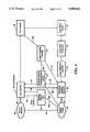
- FIG. 4is a block diagram relating to the system of the invention.
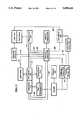
- FIG. 5is a more detailed block diagram showing control and information flow among various optical components and user interface elements of the system of the invention.
- FIG. 5Ais a block diagram indicating the interplay of the two separate but cooperating tracking methods, the fast and slow tracking loops.
- FIG. 6is another block diagram indicating joystick and template information flow.
- FIG. 6Ais a further block diagram, illustrating the functional interdependence among certain subsystems of the invention.
- FIG. 7is a schematic view in perspective illustrating the off-axis projection of a Ronchi ruling onto a curved, warped or generally spherical surface such as that of the eye, and the on-axis viewing of that projected Ronchi ruling by a camera.
- FIG. 8is a schematic representation showing an image which might be seen by the camera in FIG. 7. The image shown corresponds to the interference pattern between the projected Ronchi ruling as distorted by the target and the reference ruling.
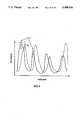
- FIG. 9is a graph plotting of light intensity versus position, relating to the imaging method shown in FIGS. 7 and 8.
- FIG. 10is a schematic representation of an objective lens assembly forming a part of the system of the invention.
- FIG. 1shows a precision laser surgery and diagnostic/analytical instrument 10 in accordance with the principles of the present invention, in the form of a work station.
- the work station 10 in this illustrated embodiment of the inventionis intended for ophthalmic surgery, with the patient to be seated in a chair 11 with his forehead against a forehead rest 12 and his chin against a chin rest 13. The surgeon/user sits a chair 14.
- the instrument and system 10 of the inventionfurther include controls 16 for a vision system and laser firing, enabling the surgeon/user to survey the topography and internal features of the tissue to be operated upon (the eye in the illustrated work station), and to precisely control the path of firing as well as the pattern of firing of a laser beam in three dimensions.
- the surgeonmay control the firing of the laser manually or with pre-programmed "templates" which can be superimposed over an image of the tissue being operated upon, and which enable an automatic tracing of a desired laser firing pattern based upon prior experience with similar surgical procedures.
- the systemcan also include a final focussing lens or front lens element 17 (an element of an objective lens assembly, as explained below), through which certain images are taken and through which the laser beam is directed at the subject tissue.
- An illuminating light beammay also be projected at the tissue through the final lens 17.
- a central column 18 of the instrument 10may contain the therapeutic laser, an illuminator, and surgical microscope, none of which is seen in FIG. 1.
- the systemalso includes an appropriate form of display means, preferably a CRT video screen 19 as illustrated.
- a foot pedal 20may be provided for the surgeon, as a safety device which will both enable the laser triggering means when sufficient pressure is exerted on the foot pedal 20, or alternatively will immediately interrupt laser firing if foot pressure on the foot pedal 20 is released.
- the light projector 21projects a Ronchi ruling onto and into the eye, and images of the Ronchi on and in the eye are analyzed by a profilometer camera (not seen in FIG. 1) which also utilizes the final focussing lens 17, sharing a portion of the optical path of the surgical microscope, the therapeutic laser, and the illuminator.
- the seating 11 and 14 for the patient and the surgeonpreferably is fully adjustable with tracks 22 for adjusting proximity to the apparatus and with full height and seat back adjustability.
- the forehead and chin rest 12, 13is adjustable.
- FIG. 2shows an example of what may be displayed on a screen 24 of the video monitor 19.
- the information on the screen 24is intended to give the user a full range of information regarding the three dimensional structure and features of the particular tissues on which laser surgical procedures are to be performed.
- the screenmay be divided into four quadrants as illustrated.
- the upper left quadrant 24amay show the image from the video microscope.
- individual cell wallsmay appear in this quadrant as indicated, with relatively high resolution and contrast. These cell walls might be the cells at the inner surface of the cornea, or corneal endothelium.
- the surgical microscopepreferably has a zoom adjustment, so that the magnification power as presented on the screen might vary from about 25 ⁇ to 500 ⁇ , as desired by the surgeon/user.
- the lower right quadrant 24d of the screencan present an enlarged plan view of an area of the patient's tissue, preferably through the full field where the surgical therapeutic treatment is desired.
- this fieldmight comprise, for example, a field of greater dimensions than the cornea for anterior segment procedures, if the surgery is to be conducted in the cornea.
- the plan view or X-Y plane shown in the quadrant 24dmay have contour plot with contour levels 26 superimposed concentrically over the image of the cornea.
- Crosshairs or crossed lines 27 and 28identify for the surgeon the precise point at which the surgical therapeutic laser is currently directed.
- crossed linesmay also indicate the line cuts which define the axis for the cross sectional plane representations of the tissue shown in screen quadrants 24b and 24c in FIG. 2.
- the crosshairs or crossed lines 27 and 28 in the quadrant 24dindicate planes at which cross sectional representations in the quadrants 24b and 24c are taken.
- the upper right quadrant 24bshows a cross section along the X-Z plane, taken along the line 27.
- the lower left quadrant 24c of the screenrepresents the Y-Z plane along the crossed line 28 shown in the quadrant 24d.
- the cross sectional representations of the quadrant 24b and 24care computer-generated images.
- the imagesare of the cornea of the eye with the epithelium surface and the endothelium surface, and the stroma located between the epithelium and the endothelium surfaces.
- a surgical procedureis to be undertaken on an aberration, foreign body, or cluster of diseased tissues 31 indicated on the two cross sectional quadrants.
- the surgical proceduremay be undertaken to modify the refractive power of an otherwise healthy cornea.
- the cross sectional representations in the quadrants 24b and 24calso include intersecting lines 32, 33, and 34, 35 to indicate to the surgeon precisely where the laser is currently targeted and focused, even though it may not currently be firing.
- boxes or windows 37 and 38may be generated on the video screen to show pertinent data relating to the tissue on which surgery is to be performed.
- some symbols on the screensuch as in a vertical strip 39 shown on the left side of the screen in FIG. 2. These symbols comprise a menu of selections for the surgeon, preferably in a branching look-up table format.
- the selection from this menucan be made from a cursor which is preferably located in the strip 39 shown on the screen and which can be manipulated by a keyboard input or preferably (in order to obviate the risks of mis-keying on a keyboard) a traction ball such as a "ball mouse", for example the products referred to commercially by the trademark "Logimouse”, such as shown at 42 in FIG. 1.
- a cursorwhich is preferably located in the strip 39 shown on the screen and which can be manipulated by a keyboard input or preferably (in order to obviate the risks of mis-keying on a keyboard) a traction ball such as a "ball mouse”, for example the products referred to commercially by the trademark "Logimouse”, such as shown at 42 in FIG. 1.
- the surgeonhas a number of options. He can take previous templates stored in memory and derived from other previous surgeries conducted by himself or by other surgeons. He can create a new template or modify an old template. This is a accomplished by superimposing a template on the screen over the ocular tissues.
- a templatecan be drawn on the screen using MacPaint (a trademark of Apple Computer, Inc.) or another software based drawing system. The surgeon "draws" in three dimensions, using for example the three screen quadrant formats 24b, 24c, 24d shown in FIG. 2.
- the surgeonmight first establish the pattern in the screen 24d in plan view, then define it in a first cross section on the screen quadrant 24c, then in another cross section in the screen quadrant 24b.
- the surgeoncan locate the cursor on a point of a template path, click the logimouse, manipulate the Logimouse to move the point to a new location, then click it again to fix the new location of the point.
- the surgeoncan locate the cursor in the middle of a closed loop path on the screen, click the Logimouse and move the entire surgical path with movement of the Logimouse, to relocate the path in the same shape. Another click fixes the new location.
- the surgeoncan use an existing template, superimpose it on the images shown in FIG. 2, then modify the pattern as desired using an edit mode of the system. In this way, the surgeon can precisely define the path of laser-induced lesions to be generated in the ocular tissues, to obtain precisely the desired surgical therapy.
- the controls 16 shown in FIG. 1include a joystick 43 of the well known potentiometer type.
- This joystick 43may be used by the surgeon to move the target position, i.e. the intersection of the crosshairs 27 and 28 in FIG. 2, to the left and right or up and down as seen in the quadrant 24d of FIG. 2. This is in respect to a plan view of the tissue, such as the eye in ophthalmic surgery.
- the joystickis used to move the crosshair or section line 28 to the left in the quadrant 24d, in the X-Y plane as shown, this will similarly move the crosshair 33 to the left in the X-Z plane quadrant 24b immediately above.
- the movement of the line 28will have the effect of changing the cross sectional representation in the screen quadrant 24c, since the movement of that line also has the effect of changing the point at which the Y-Z plane cross section is taken.
- the horizontal-appearing crosshair 27 in the quadrant 24dis moved down as seen on the screen, for example, this will have the effect of moving the vertical crosshair in the quadrant 24c, and it will have the concurrent effect of showing a different cross sectional shape in the upper right quadrant 24b, which is the X-Z plane.
- the graphical, computer-generated representations shown in the three quadrants 24b, 24c, and 24d in FIG. 2are merely examples of the way in which pertinent information can be presented to the physician.
- the menu 39 at the left of the screenthere preferably are provided other types of presentations which can be selected by the physician.
- the joystick controller 43also contains the laser fire sequence command control 43a.
- a laser fire safety interlock foot pedal(not shown) requires two separate coordinated actions to commence a laser firing sequence.
- Other control and indicator featuresinclude the enabling (or disabling) of internal safety interrupts, a light emitting diode display which indicates when the tracking system and target acquisition system is operational and on-target, an LED which lights up when the system components have successfully been verified to be performing within system specification ranges, an LED indicating power is on, and a video display to assist in detecting location of a system malfunction. Additional safety LEDs acknowledge sufficient pressure on the laser fire safety interlock in a foot pedal, and whether the microprocessor generated template pattern is in control of the firing sequence.
- FIG. 3shows in exploded perspective view a preferred system of optics for the instrument of the invention.
- a surgical laser 50is shown in a common optical path with an axial illuminator 51, a surgical microscope 52, shown exploded, and cameras 53a and 53b which have the functions of reading information from the tissue for computer generation of the cross sectional views shown in FIG. 2, and also tracking the tissue with movements of the patient, by finding and recognizing a given feature, through signals sent to the computer and programming, after that feature has moved to a new location.
- the two camerasare sometimes referred to collectively hereinas the tracking/profilometer camera 53.
- the camera 53bpreferably includes a video camera, capable of taking images at a high rate of speed and is used for profiling and topographic imaging, low speed tracking, and image recognition.
- the camera 53apreferably contains dual linear, and preferably but not necessarily orthogonal, array detectors for high speed tracking.
- the tracking/profilometer camera 53uses common optical elements with the other equipment, namely the tracking servo mirror 54 and the final focusing lens or front element lens 17.
- the tracking/profilometer camera 53is intended to cover a certain field of view of the patient's tissue, such as an eye 58 (or a portion of an eye) shown in FIG. 3.
- Lenses 59focus the image onto the faceplate of camera 53. It is not intended that the camera's image be moved laterally with respect to the tissue being viewed--only that it follow the tissue via the tracking servo mirror 54.
- the tracking servo mirror 54which may be controlled by a piezo-electric (or similar) actuator, is shifted in its aim about X and Y axes in response to movements of the patient's tissue, so that the center axis of view of camera 53 always returns to the same point on the tissue.
- the focusing lens 17is adjusted as to focus, along a Z axis, in response to shifts in the depth of the subject tissue feature, so that the system always returns to a focus on the desired depth point in the tissue.
- the distance of the patient's eye 58 from the final focussing lens 17must be an appreciable distance, one great enough to allow the patient to feel comfortable.
- a distance of about 50 mmis considered minimum. It is preferred, however, that a more considerable distance be employed, at least about 100 mm.
- the positioning mirror 61is steerable under the control of the surgeon/user.
- the mirror 61is adjustable about X and Y axes, and it therefore lets the physician select different locations for firing the laser within the field of view of the camera 53.
- an axis 62 of the three elements 52, 50 and 51 to the right in FIG. 3will only be coincident with the axis of view of the tracking camera 53 when the surgeon aims the laser directly at the center of the field of view of the camera 53. In other instances they will share the same "optical path" via elements 54 and 17, but they will not be on identical axes.
- the function of the positioning mirror 61is better understood with reference to FIGS. 1 and 2, as well as FIG. 3.
- thishas the effect of moving the crosshairs shown in the computer-generated screen quadrants shown in FIG. 2, and of shifting the cross sectional image representations shown in the quadrants 24b and 24c.
- the movement of the joystickshifts the orientation of the directional positioning mirror 61 to the same extent, which has the effect of (a) moving the surgical microscope image in the screen quadrant 24a to the left or right or up or down; (b) moving the actual aim of the therapeutic laser beam from the laser 50, which is precisely coaxial along the axis 62 with the surgical microscope, to a real aiming point which is coincident with the computer-generated aiming points shown in the screen quadrants 24b, 24c, and 24d; and (c) similarly changing the aim of the illuminator 51, which provides light for imaging by the surgical microscope 52.
- the therapeutic laser 50may be a frequency multiplied solid state laser (Nd:YAG, Nd:YLF, Erbium or others) which may be either flash lamp or diode pumped, or an argon, argon pumped dye, excimer, excimer pumped dye, nitrogen, nitrogen pumped dye, or any of a host of different lasers, or combinations thereof, currently available or in development.
- the present inventioncan be used with any laser by specifying different coatings where necessary for the optical surfaces.
- a quartz and magnesium fluoride focusing elementis available as the element 17 to accommodate ultraviolet lasers.
- the present inventionis not laser specific, but is intended as a surgical instrument intended for utilizing any therapeutic laser more efficaciously.
- the laser 50preferably produces a pulsed beam which is controllable as to the level of energy per pulse, pulse peak power, and repetition rate.
- Beam expander lenses 68, 69preferably are positioned just downstream of the laser 50 and adjusted so as to expand the diameter of the laser pulse emerging from the laser cavity and collimate it so that a parallel but expanded beam of light emerges from the lens 68.
- the expanded, collimated beamarrives incident upon the final lens 17, and the expanded beam substantially fills the lens.
- a large-diameter beamis focused by the lens 17, so that only at the point of focus within the eye is the diffraction limited pulsed laser beam effective to generate the desired therapeutic lesions in the eye.
- the illuminator light beamfirst is reflected off a mirror 72, then off the reflective surface of a beam splitter mirror 73, to join substantially coaxially with the path of the laser beam along the beam axis 74. Both beams are then reflected off a mirror 76 and off a reflective surface in a polarizing beam splitter 77.
- the illumination beam and the laser beamthen join the common axis 62 with the axis of view of the video microscope 52, as illustrated.
- the surgical microscope 52has zoom optics for adjustable magnification at the screen in the range of about 25 ⁇ to 500 ⁇ , for example. This enables the surgeon to view a very narrow field, e.g. tens of microns in width, or a much wider field, at lesser magnification. This is useful in enabling the surgeon to assure himself that he is aimed at and focused at a particular desired region. Zooming can be effected through use of the branching look-up table 39 shown in FIG. 2, with the ball mouse or trackball assembly 42 (see FIG. 1) controlling the selections by the surgeon.
- the surgical microscope 52preferably comprises an intensified video camera, for example a silicon intensified target (SIT) tube camera. Alternatively it can be a conventional video camera in combination with a microchannel plate intensifier. In either event the camera's sensitivity preferably is about 1000 times that of a normal video camera, enabling the system to look at weakly scattered light and targets poorly illuminated for the desired levels of high magnification at large working distances.
- an intensified video camerafor example a silicon intensified target (SIT) tube camera.
- SITsilicon intensified target
- the camera's sensitivitypreferably is about 1000 times that of a normal video camera, enabling the system to look at weakly scattered light and targets poorly illuminated for the desired levels of high magnification at large working distances.
- the final focusing lens 17 shown in FIGS. 1 and 3is controlled automatically by the instrument as well as being controlled by the surgeon via the joystick 43.
- the computer and programming sensethrough inputs of the tracking and profilometer camera 53, that the subject tissue has moved and when the new location has been confirmed, the tissue may be at a different depth from the lens 17, as well as at a different lateral position in the field of view. This necessitates a change in focus of the lens 17, and this is effected automatically under control of the computer.
- the tracking and profilometer camera 53has optics which give it a wide depth of field, so that features can be recognized even at different depths, before focus is adjusted.
- these featurescan be tracked while still in acceptable focus, and the final lens 17 can then be adjusted accordingly, to center the focus of the system at the new location. This is preferably accomplished via the profilometer camera 53b at its frame rate, but not by the much faster tracking camera 53a, as explained further below.
- the surgeonoften desires to change the depth at which the surgical microscope 52 is focused (the upper left quadrant 24a in FIG. 2 shows this video display), and simultaneously of the surgical laser 50. This is accomplished by rotation of the joystick 43 in one direction or the other, to focus the system more deeply or more shallowly, via the lens 17. This of course has an effect on the focal point of the tracking detector and profilometer camera 53 as well. It will change the center of focus of the profilometer and it will move the horizontal crosshairs down in screen quadrants 24b and 24c, but the depth of field of the profilometer camera 53b is broad enough that the images will still be obtained. The surgeon's adjustments of the focus of the final lens 17 are superimposed on top of the automatic adjustments effected by the tracking system, and net focus changes are carried out by the system.
- the tracking detectorconsists of high speed linear array detectors in two orthogonal directions and an array processor such that updated position information is fed to the tracking mirror at frequencies substantially higher that the repetition rate of the laser or the frame rate of the imaging cameras.
- the response time of the tracking detector and processorwill be substantially under one millisecond.
- the final focussing lens 17forms a part of a split microscope objective lens assembly of the system of the invention.
- the lens 17comprises the front element of the objective lens assembly, while the rear element of the objective lens comprises one of the elements of the tracking detector and profilometer camera 53 or of the surgical microscope 52 or of the laser 50 optics or of the illumination source 51.
- the back element of the objective lens assemblyis indicated at 70.
- the image plane of this back element of the objective lenscan represent an element of any of the components mentioned above, such as the intermediate focal plane of the surgical microscope, the face plate of the profilometer camera, the face plate of the tracking detector array, or the condenser of the illuminator.
- the front element of the objective lensis common to a variety of optical assemblies.
- the collimated laser beamis inserted via a beam splitter between the objective elements, hence the front element of the objective lens is likewise common to the laser beam assembly.
- the servo tracking mirror 54actually is positioned inside the objective lens assembly, as illustrated schematically in FIG. 10. (The final element has been designed to have sufficient field to accommodate the small misalignments caused by the tracking mirror.) This enables the system to achieve rapid tracking of ocular features (or other tissue features) in an efficient and relatively simple assembly, without moving an entire objective lens in following the sometimes rapidly moving features.
- the moving masscan be limited in the present invention to a very thin mirror 54 (e.g. a mirror of a few mm thickness with a flatness of a wavelength or better).
- the very thin, lightweight mirroris capable of achieving very rapid tracking on rapidly moving objects by quick changes of the aiming direction of the mirror 54, along X and Y axes. This may be accomplished using a piezoelectric or similarly driven servo mirror, a type of mirror control known in the optical systems industry, albeit not in the ophthalmic community.
- FIG. 10illustrates schematically that the thin, lightweight mirror is mounted to a high speed servo driver to form the servo mirror assembly 54.
- An electrical leadis shown leading to the servo interface driver 54a.
- the mirror 54redirects images which pass through the final focussing lens 17, the front element of the objective lens assembly.
- the lens 17has a sufficiently large working field to accommodate the image variation off-axis in the lens.
- FIG. 4is a functional block diagram showing principal components of the precision laser surgery system of the invention.
- the surgeon useris indicated at 80, with the patient/target indicated at 81. Interaction between the surgeon and the patient is indicated by a dotted line 82.
- the dashed line 82represents the surgeon's indirectly carrying out the surgical procedures on the patient, and the patient's tissue indirectly feeding back information and data, through the instrument, to the surgeon, via the video display 19.
- surgeon/useris provided the option of both direct observation and tactile manipulation of the patient/target because of the compactness of the design of the instrument and the large desired working distance between the final focusing element 17 and the patient 58.
- the user interface of the systemis indicated at 83.
- the surgeon userinputs instructions and commands to the user interface 83 and the user interface feeds back information to the user, principally via the video screen 19.
- Thisis indicated by a line 84.
- the user interface 83comprises for the most part the video screen 19, the mouse or trackball assembly 42 for making selections, the joystick 43, the fire control button 43a and various buttons and numerical displays indicated in FIG. 1 in front of the surgeon user.
- a traction ball(the "Logimouse" 42 shown in FIG. 1 but not shown in FIG. 4) is placed near the joy stick to enable the surgeon/user to control and select from among the various software options available.
- Rotation of the traction ballcontrols the position on the video screen.
- a button next to the ballenables special features on the screen and allows the user to superimpose on the video generated corneal images the proposed therapy.
- computer graphics software packagessuch as MacPaint and MacDraw form a portion of the basis for providing the surgeon/user access to defining surgical templates.
- Other buttonsallow the surgeon/user to switch from selecting previously defined templates, to modifying or creating templates.
- FIG. 4shows separate blocks 86, 87 and 88 for the positioning assembly, the target tracking assembly and the fire control, all indicated as being under control of the surgeon user by lines from the user interface with arrowheads directed at these blocks 86, 87 and 88.
- the block 88indicates an internal fire control activated by the push of the button 43a shown in FIG. 1, and this in turn activates the laser power source, i.e.
- the laser power source 50is connected to a laser pulse conditioner indicated by the block 89, which produces a pulsed laser beam of the desired shape.
- the beampasses through a laser diagnostic assembly 91, which serves the purpose of monitoring the continued pulse-to-pulse performance of the laser to insure it is performing to specification.
- the beamis then indicated as being passed through the positioning assembly 86 (not all optical components are indicated in FIG. 4).
- the positioning assembly 86includes the laser beam directional positioning mirror 61, which is under the control of the surgeon via the joystick 43 as discussed above.
- a dashed line 92indicates the laser beam's action on the target, i.e. the patient.
- the positioning assembly 86also includes the automatically controlled tracking servo mirror 54 (see FIG. 3), as well as the front objective element 17.
- the positioning assembly 86is shown in FIG. 4 as receiving control instructions from the target tracking assembly 87, and this control amounts to control of the servo mirror 54 to adjust the mirror whenever the patient's target tissue moves.
- the patient/target 81is shown as sending information to an imaging system 93 and to a position analysis tracking system 94.
- the imaging system 93comprises the surgical microscope 52, which presents the video image exemplified in the upper left quadrant in FIG. 2.
- An arrow 95indicates transmission of the video information to the video display, forming a part of the user interface 83.
- a control arrow 96 between the user interface and the imaging system 93indicates that the surgeon may control the magnification of the surgical microscope, as discussed above.
- the position analysis tracking system 94includes the tracking/profilometer camera 53 (the camera/detectors 53a and 53b) and, in a preferred embodiment, the Ronchi ruling light projector 21 shown in FIG. 1.
- This subsystem 94receives images from the patient/target 81, as discussed above, for detecting and following any movement of the patient's tissue.
- An information arrow 97is shown between the position analysis tracking system 94 and the user interface 83, indicating stabilization of the video images by the subsystem 94, as well as the feeding of information to the display for the profilometer images.
- the subsystem 94includes the microprocessor and programming which are able to analyze images taken by the profilometer/tracking camera/detectors 53 and to determine from the camera/detector data when features have moved and to relocate those features and calculate new coordinates for mirror position. It includes the slow tracking profilometer camera 53b and the fast tracking detector 53a, as well as slow and fast logic loops. Some of these functions are described further with reference to FIGS. 5A through 9.
- position analysis meansIn the claims, the terms “position analysis means”, “target tracking means”, and “tracking positioning means” are used. These terms correspond generally but not precisely to the blocks 94, 87, and 86 respectively in FIG. 4. There is some overlap in the terms, as further explained below.
- FIG. 4shows an information or control arrow 98 leading from the positioning assembly 86 to the position analysis tracking system 94. This represents feedback from the mirror assemblies as to their actual position. It also includes confirmation that the mirror was physically moved, i.e. that the instruction to the mirror resulted, where indicated, in a physical displacement. If this move does not occur, the system loops back to the target tracking assembly 87 which sends a signal 104 to disable the laser firing.
- the position analysis tracking system 94is shown sending information or commands to the target tracking assembly 87, by a control arrow 101.
- the information or instructionscan comprise new coordinates for the mirror position 54.
- the target tracking assembly 87translates the new coordinates into instructions for the mirror drivers (arrow 102 to the positioning assembly 86), i.e. the servo mirror 54.
- This instructionincludes coordinate transform information and instructions for the servo mirror 54 to turn to a new angle which will again be centered on the same features.
- the target tracking assembly 87also sends commands regarding the focus, and thus adjusts the focus of the final focussing lens 17 as discussed above, and the lens 17 should be considered as forming a part of the positioning assembly 86 (preferably in a slow tracking loop as discussed below).
- the final focussing lensalso forms a part of the imaging system 93, in the sense that the surgical microscope receives light on a path which passes through this lens 17, and the focus of the imaging is adjustable by the surgeon/user.
- the target tracking assembly 87if unable to track the moved feature to a new location within the time allotted (which may be 1/30 second or faster in one embodiment or 1 millisecond in another), will send an instruction to the internal fire control 88, to abort firing of the laser.
- a double-ended arrow 106 in FIG. 4 between the user interface and the positioning assemblyindicates control by the physician, via the joystick 83, of the directional positioning mirror 61, as discussed previously; and also feedback from the positioning assembly to the user interface.
- Such feedbackwould include the actual movement of the crosshairs indicating position, as described with respect to FIG. 2, as well as changes in the cross-sectional shapes as the cross-sectional cutting planes are moved by the physician, if these image formats are used.
- This linealso carries internal encoders indicating that instructions have been carried out.
- the system of the inventionis useful to the surgeon as a diagnostic and analytical tool, aside from its uses in actual surgery.
- the systemprovides for the doctor highly stabilized images of the patient's tissue, particularly the ocular tissue, not achievable with instruments prior to this invention.
- the doctoris given a real-time display of the tissues, with tracking and stabilization in real time.
- the inventiontherefore gives the doctor a very important tool in analysis and diagnosis of a patient's condition, and the invention should be understood to encompass the system as described even without the surgical laser beam itself.
- the systemwith its computer-generated images on the display screen as well as direct video microscopic images displays of the patient/target, gives the doctor a means of visualizing the eye condition, as a replacement for the doctor's directly looking at the target tissues.
- FIG. 5is a block diagram showing in greater detail some of the individual control and informational feedback functions regarding the components of the system of the invention.
- FIG. 5shows a microprocessor or central processing unit in a block 110, and programming 111 communicating with the microprocessor.
- the user interfacehas some communication with the microprocessor 110 and some controls which do not involve the microprocessor. For example, if the surgeon wishes to select a template for surgery, or merely to change the display on the video screen (FIG. 2) for the purpose of selecting a different type of presentation, or for imposing a different surgical path on the screen, etc., these communications are with the processor, which controls the computer-generated images on the screen as well as controlling many other functions in the system.
- the microprocessor 110also controls the tracking mirror or servo mirror 54, as indicated.
- the microprocessorcontrols the mirror in response to input from the tracking/profilometer camera 53 (the cameras 53a and 53b) in conjunction with the program software 111.
- the microprocessorhandles the position analysis and the low speed target tracking (mirror instruction) as indicated in the blocks 94 and 87 in FIG. 4 and outputs a signal in response to the results of the tracking, to the tracking mirror 54 (dashed line 109 in FIG. 5).
- the fast tracking detectors 53a in camera 53will communicate directly with a servo interface and drivers 54a which directly control the servo mirror 54.
- the unit 54acan be a dedicated microprocessor or other logic unit having the capability of carrying out the logic sequence needed for pattern recognition, coordinate transform analysis and generating instructions to the mirror drivers to appropriately adjust the mirror 54.
- the servo interface driverincludes some of the logic functions of the block 94 in FIG. 4, as well as the functions of the block 87.
- This preferred embodiment of the inventionalong with more responsive servo mirror designs, allows a much faster closed loop tracking response time than via the microprocessor 110.
- the tracking mirrorthus rotates to the appropriate new position. This is confirmed in the microprocessor by the location of the image itself, after the mirror has completed its instructed motion. However, as mentioned above, if the microprocessor and programming determine that the feature has not been recognized in the next scan of the target region (or within a pre-selected number of said subsequent scans, depending on the desired tracking rate as determined by the requirements of a given surgical procedure), the microprocessor will immediately interrupt laser firing (as indicated on a control line 112) and it will also interrupt the execution of the template program, vis a vis the movement of the position mirror 61 which steers the path of laser. This is indicated on control line 113 in FIG. 5.
- the template programwill generally also involve adjustments in the focus of the final lens element 17, and this is indicated by the control line 114 in FIG. 5.
- the interruptpreferably lasts only until the feature is recovered via the slow tracking loop (discussed further below), if in fact the feature is recovered.
- a dashed control 115 from the servo tracking mirror 54 to the laser aim blockindicates that the laser aim is steered along with the tracking (see FIG. 4), but as the laser and surgical microscope lines of sight are coaxial, the field of tissue being viewed and the laser are always tracked as one.
- the microprocessorsends signals to the video screen (along control line 116), the content of these signals relating particularly to the computer-generated topographical images, examples of which are shown in the screen quadrants 24b, 24c and 24d in FIG. 2.
- the microprocessoralso controls the display of the branching look-up table 39 shown in FIG. 2, as well as other displays on the screen other than the video microscope image itself. If the video screen and the microprocessor comprise a "touch screen" system as mentioned above, then the control line 116 also relates to this feature, and a further control line 117 is indicated as a dashed line in FIG. 5 from the video display 19 to the microprocessor, representing the touch screen functions.
- a control line 118 from the user interface to the microprocessorindicates the surgeon user's selections made by input controls other than touch screen.
- the control line 118also indicates another user input to the microprocessor 110 active when the user steers the field of vision and the aim of the laser. Such deliberate control by the surgeon will indirectly control the positioning mirror via the microprocessor, along the control lines 118 and 113.
- Its signals to the microprocessorare also used by the microprocessor to adjust the computer-generated images accordingly, reflecting precisely the change in aim selected by the physician and using the information from the profilometer camera 53b.
- FIG. 5shows a similar control situation with respect to the surgeon's control of the depth to which the laser is focused i.e. via the final focussing lens 17.
- a simultaneous signal representative of the changeis sent to the microprocessor, along the control line 123.
- FIG. 5indicates that the surgeon user has direct control of the zoom feature to adjust the magnification of the surgical microscope, indicated in the block 124.
- tracking subassemblieswhich compose the preferred embodiment of the tracking subassembly.
- Thesecomprise a relatively slower system or tracking loop operating at or near maximum video frame rates (usually 30 hertz) and a fast system or tracking loop operating faster than the attainable video rate.
- the slower systemutilizes the image from the profilometer camera 53b and analyzes essentially frame by frame the shift of salient features in the image.
- the positional shifts, as computed by the processor 110,are utilized to reposition the servo mirror 54.
- This systemis comparatively slow but has the advantage of being able to find an absolute position on the target even after a temporary loss of tracking.
- this slower systemwill automatically store in memory the last position in the firing sequence so that once the target is again reacquired, the exact location of the next point in the firing sequence can be determined automatically and the servo mirror be repositioned accordingly.
- the faster systemuses an orthogonal pair of linear detector arrays in a high magnification focal plane.
- a dedicated processor or simpler servo interface driver 54aanalyzes the phase shift of, for example, specific Fourier modes of the signal in successive readouts of the arrays.
- the linear array detectors and dedicated processor or servo-driverare extremely fast (e.g., greater than 10 KHZ for complete array readout); thus, the faster system is limited in speed only by the response time of the servo mirror and drive 54. However, because of its limited data collection and analysis, the faster system is not designed to recover an absolute location after a transient tracking loss.
- the servo mirror 54may utilize, for example, a motor driven mount for the slower tracking system and a piezo-electric driven mirror for the fast system.
- FIG. 5Ais a block diagram specifically showing functions of the tracking system included in the present invention.
- the preferred tracking systemincludes a slow tracking loop and a fast tracking loop, as discussed above.
- the tracking servo mirror 54 and the imagecomprise a part of both the fast tracking loop and the slow tracking loop.
- the slow tracking looppreferably includes the microprocessor control or CPU 110, sending signals to the tracking mirror 54, including the mirror drive, and is primarily limited in this embodiment of the invention by the maximum attainable video camera frame rate.
- the tracking mirror 54controls the region of the target plane to be imaged as indicated. The image is fed to the fast tracking detector which is discussed above as the tracking camera 53a.
- This camera or detectorsends information relating to position analysis to a dedicated logic analyzer or servo interface 54a capable of issuing command signals to the mirror 54 to adjust the mirror position to aim at the new position of the feature as determined by the processor 54a and the fast tracking detector or camera 53a.
- this fast trackingpreferably occurs at approximately 1 millisecond or faster response time, limited only by the response time of the mirror mount drives when loaded with the tracking mirror.
- the microprocessor control or CPU 110also sends signals to the tracking servo mirror and drive 54.
- This slow tracking loopincludes the image, as shown in the drawing, and the profilometer camera 53b receiving the images.
- the profilometer camera 53bsends image information to the CPU 110, which is capable of finding a feature characteristically, if possible, whenever the fast tracking loop has lost the feature.
- the CPU 110has the capability of searching for the feature in the entire field of view of the profilometer camera 53b and in generated cross-sectional topographic images, and issuing commands to the tracking servo mirror and drive 54 accordingly.
- the slow tracking loopfurther continuously tracks the depth as well as the position in the X-Y plane consistent with the three dimensional information derived from the profilometer camera 53b which constitutes the detector for the slow tracking loop.
- the slow tracking loopin addition to acting as a backup mechanism for the fast tracking loop, also serves as the primary control system that adjusts the position, at the maximum video frame rate, of the front element of the final focusing lens 17.
- the dedicated microprocessor or other servo unit 54aissues an interrupt from the fast tracking loop to the CPU 110, when tracking of the feature is lost. Since both control signals (from the CPU 110 and from the dedicated microprocessor 54a) are always being fed to the tracking servo mirror and drive 54, the instructions from the CPU 110 take over when the fast tracking loop signal is interrupted. Normally, the unit 54 will operate on the fast tracking signal from the microprocessor 54a whenever that signal is being received, ignoring and overriding the other tracking signal from the CPU 110.
- Trackingis considered to be effectively lost when a tracked feature of the image is not found from array signal frame to frame (or over a period of several frames) or if the feature progressively moves or drifts farther away from frame to frame. This latter event would signify that even though the feature is being tracked by the logic loop(s), instructions are not being properly carried out at the aiming mirrors. Examples of tracking loss not associated with the logic loop are failure of the signal to be effected by the servo drivers, required mirror motion exceeding the limiting displacement of the servo driven actuators, malfunction of the drivers or slides.
- FIG. 9is an illustration of the manner in which the tracking system of the invention may function in one preferred embodiment.
- two curvesappear corresponding to two different time scans indicating light intensity as detected by either one of the orthogonal linear scanning arrays of the fast tracking detectors.
- Curve Arepresents the light intensity pattern which might have been observed on a given small feature of the tissue, for example a feature on or in the eye, at an initial time A.
- Curve Brepresents a curve generally similar to curve A but shifted to the right.
- the programming or fast tracking servo unit 54arecognizes that the pattern of curve A has shifted or at least has moved away from its initial position.
- the systemsearches for a similar curve pattern, which because of orthogonal shifts usually will not be identical. If it finds scan function curve B is sufficiently similar to the previous scan function curve A that it must represent the same feature, then it issues an appropriate command to the tracking mirror via the dedicated servo processor to move to the new position.
- the new positionis a correction input to the mirror via a correction signal based on the determined offset.
- the programmingincludes parameters enabling the system to recognize the shifted pattern as the feature, provided sufficient similarity exists within a selected range.
- FIG. 6is another functional block diagram, indicating joystick and template information.
- the joystick 43is shown at the bottom of the figure. It sends signals along a line 130 to a central processing unit, which is the microprocessor 110.
- the CPU 110is shown as connected to a number of other components. For example, it is shown as sending information to an I/O unit for record keeping.
- the transmissionsmay include, for example, patient history records to be printed or stored.
- the ball mouse or Logimouse 42is shown in FIG. 6, controlling templates, i.e. selecting pre-recorded templates or creating new ones for the surgery. In turn, the selected template information is put into the CPU.
- the CPU 110sends control signals to a dedicated I/O board 132 which is used for driving motors associated with the directional positioning mirror 61, as well as for driving Z-axis adjustments through the final focussing lens 17.
- the solid control line between the dedicated I/O board and the turning mirror 61 and final lens 17indicates the use of the automated template procedure. On the other hand, as indicated in dashed lines, the surgery can be accomplished manually with the indicated optional manual override.
- a commercially available dedicated I/O board 132is capable of handling 16 analog channels and three digital channels in the currently described embodiment. It handles diagnostic information relating to laser status, position status, tracker mirror status, and other diagnostics which may be implemented as needed such as intraocular temperature, intraocular pressure readings, and surface wave propagation measurements to enable calculation of the Young's modulus and other elasticity constants in an effort to determine applicable constitutive relations.
- diagnosticsrelating to laser status, position status, tracker mirror status, and other diagnostics which may be implemented as needed such as intraocular temperature, intraocular pressure readings, and surface wave propagation measurements to enable calculation of the Young's modulus and other elasticity constants in an effort to determine applicable constitutive relations.
- the sensors for these conditions of the eyeare not shown in the drawings, but can be incorporated in the system of the invention.
- FIG. 6Ais another block diagram indicating operation of principal aspects of the system of the invention.
- FIG. 6Ashows the looping of information and control signals in the system, particularly when a pre-programmed surgical template is used to control laser position and firing in the surgical procedure.
- the eye 58is shown as sending information (via the tracking/profilometer camera 53, not shown) to a box labeled Diagnostic Position Measurement, Tracking and Topography. This indicates the derivation of such information from the eye via the camera and the microprocessor and programming 110 and 111 (FIG. 5).
- This blockincludes the sensors/cameras 53a and 53b and analysis loops, including the computer 110 and the dedicated microprocessor 54a. It includes tracking in the logic loop.
- the derived information relating to the topography of the eye tissues and the position of the camera on the eyeis sent to the tracking and stabilization block which stabilizes the motions of the eye, relocating a feature after it has moved and repositioning the vision system to again be centered on the same feature.
- the Tracking and Stabilization blockrepresents the tracking mirror 54 and the positioning mirror 61 (under template program control), as well as mirror drives for these mirrors.
- FIG. 6Aindicates the diagnostic position measurement and tracking block sending information to a block entitled template controlled surgical laser.
- This informationcomprises confirmation that the template is still positioned correctly, i.e. that the targeted feature of the eye has been tracked within a preselected time allotted, so that the images of the eye remain stabilized. If this confirmation is not sent (or a contrary signal could be sent to signal that tracking is lost), the template controlled laser firing is immediately interrupted, as discussed above.
- the arrow from the template controlled laser toward the eye via the tracking servo mirror and positioning mirrormerely indicates the conducting of the laser surgery on the eye via the two mirrors, and that the laser firing sequence is interrupted and discontinued in the event the tracking system loses stabilization of the image.
- the arrow in FIG. 6A from the diagnostic position measurement block to the template controlled laseralso indicates the feed of information, when called for by the surgeon, from the position measurement assembly to the template control system, to assist the surgeon in setting up a template as desired for the contemplated surgery. This information also assists the surgeon is positioning the template.
- the Template Controlled Surgical Laser block in FIG. 6Ashould be considered as including the user interface, the computer and memory storage device relative to creating, modifying, storing, and executing surgical template programs.
- FIG. 6Ahelps illustrate the interdependence of the three depicted subassemblies of the invention--the diagnostic position measurement and logic loop tracking, the tracking mirrors and the template controlled laser firing.
- FIG. 6Aillustrates that all of these important components must operate in real time. None can operate with any significant delay, or the system would be rendered ineffective or unsafe.
- the diagnostic position measurement/tracking subsystemoperates substantially instantaneously.
- the tracking systemmust recover the image position faster than the repetition rate of the laser.
- the fast tracking systembe capable of operating at or faster than 1 KHZ. Recovery of the image within a very short time period is necessary to enable the template-controlled surgery to proceed, since if any significant delay occurs, it would be unsafe to fire the laser--it could be fired at the wrong point.
- the template controlled laser firingmust also occur precisely in accordance with the preselected targeting sequence. It is the tracking system (including diagnostic, tracking and mirror movement) which is the critical link in this feedback loop shown in FIG. 6A. As noted above, if the tracking subsystem fails to move the servo controlled turning mirrors to maintain the target within acceptable error tolerances, then the template-controlled laser firing will be disabled until the images are again reacquired or until the surgeon re-initiates the program.
- the template-controlled laser firingwill be interrupted until the images again are acquired and the appropriate position in the template firing sequence is recovered.
- FIGS. 7 and 8indicate schematically one example of a three dimensional mapping system which may be used in conjunction with the vision system of the invention.
- a Ronchi projector 21is indicated, with a light source 126 shown projecting a light beam through a Ronchi ruling 127 as indicated.
- the Ronchi rulingmay comprise a plurality of parallel equally spaced lines.
- the beamstrikes the subject tissue, e.g. the eye 58, placing the ruling across several non-planar surfaces of the eye.
- the Ronchi projection beamis off-axis from the axis of the final focussing lens of the system, and FIG. 7 schematically indicates the tracking/profilometer camera 53 as being on-axis.
- the profilometer camera 53btakes an image of the Ronchi projection from the non-planar surfaces of the eye, through a reference Ronchi grating schematically indicated at 128, and this image might appear, for example, as shown in FIG. 8.
- the so-called Moire fringes resulting from the interference (masking) between the projected and reference gratings or rulingsappear as curved lines 129 as projected on the curved surfaces of the elements of the eye.
- an important featureis that the reference Ronchi grating or ruling resides in the computer memory and the interference (masking) occurs electronically on the detected image.
- the precise positioning of these curved linescan be analyzed to determine the precise shape and location of all elements illuminated by the Ronchi projection. Such analysis is well known to those skilled in the art and does not in itself form an important feature of the present invention, other than for the computer generated interference (masking) of the projected Ronchi grating or ruling with the computer generated reference grating or ruling.
- FIG. 7further illustrates one preferred construction of the Ronchi projector.
- the light source 126sends the beam through a UV and IR filter 132 and a condensing lens 133, as well as a polarizer 134.
- the filtered, polarized beamis then sent through the Ronchi ruling 127 and through a focussing lens 136 toward the eye 58 or other tissue to be operated upon.
- the light source 126can comprise a diode laser or incandescent source.
- common or modified public domain specular techniques using distributed light sourcesmay be used to generate certain mapping and profile data.
Landscapes
- Health & Medical Sciences (AREA)
- Ophthalmology & Optometry (AREA)
- Surgery (AREA)
- Life Sciences & Earth Sciences (AREA)
- Biomedical Technology (AREA)
- Veterinary Medicine (AREA)
- Heart & Thoracic Surgery (AREA)
- Nuclear Medicine, Radiotherapy & Molecular Imaging (AREA)
- Engineering & Computer Science (AREA)
- Animal Behavior & Ethology (AREA)
- General Health & Medical Sciences (AREA)
- Public Health (AREA)
- Physics & Mathematics (AREA)
- Optics & Photonics (AREA)
- Vascular Medicine (AREA)
- Molecular Biology (AREA)
- Medical Informatics (AREA)
- Laser Surgery Devices (AREA)
- Eye Examination Apparatus (AREA)
- Microscoopes, Condenser (AREA)
- Radiation-Therapy Devices (AREA)
Abstract
Description
Claims (44)
Priority Applications (14)
| Application Number | Priority Date | Filing Date | Title |
|---|---|---|---|
| US07/307,315US5098426A (en) | 1989-02-06 | 1989-02-06 | Method and apparatus for precision laser surgery |
| PCT/US1990/000668WO1990009141A2 (en) | 1989-02-06 | 1990-02-06 | Method and apparatus for precision laser surgery |
| EP19900904085EP0426779A4 (en) | 1989-02-06 | 1990-02-06 | Method and apparatus for precision laser surgery |
| KR1019910700829AKR920700584A (en) | 1989-02-06 | 1990-02-06 | Precision laser surgery method and device |
| AU51612/90AAU651313B2 (en) | 1989-02-06 | 1990-02-06 | Method and apparatus for precision laser surgery |
| CA002009368ACA2009368C (en) | 1989-02-06 | 1990-02-06 | Method and apparatus for precision laser surgery |
| CN90100585ACN1045028A (en) | 1989-02-06 | 1990-02-06 | Method that precision surgery is used and instrument |
| JP02504019AJP3095079B2 (en) | 1989-02-06 | 1990-02-06 | Method and apparatus for precision laser surgery |
| CA002339880ACA2339880C (en) | 1989-02-06 | 1990-02-06 | Method and apparatus for precision laser surgery |
| US08/523,738US6099522A (en) | 1989-02-06 | 1995-09-05 | Automated laser workstation for high precision surgical and industrial interventions |
| US09/543,840US6726680B1 (en) | 1989-02-06 | 2000-04-05 | Automated laser workstation for high precision surgical and industrial interventions |
| US10/124,891US20020173778A1 (en) | 1989-02-06 | 2002-04-17 | Automated laser workstation for high precision surgical and industrial interventions |
| US10/125,261US6913603B2 (en) | 1989-02-06 | 2002-04-17 | Automated laser workstation for high precision surgical and industrial interventions |
| US10/632,462US20040059321A1 (en) | 1989-02-06 | 2003-08-01 | Automated laser workstation for high precision surgical and industrial interventions |
Applications Claiming Priority (1)
| Application Number | Priority Date | Filing Date | Title |
|---|---|---|---|
| US07/307,315US5098426A (en) | 1989-02-06 | 1989-02-06 | Method and apparatus for precision laser surgery |
Related Parent Applications (1)
| Application Number | Title | Priority Date | Filing Date |
|---|---|---|---|
| US47565790AContinuation-In-Part | 1989-02-06 | 1990-02-06 |
Related Child Applications (3)
| Application Number | Title | Priority Date | Filing Date |
|---|---|---|---|
| US47565790AContinuation-In-Part | 1989-02-06 | 1990-02-06 | |
| US84337492AContinuation-In-Part | 1989-02-06 | 1992-02-27 | |
| US09/543,840Continuation-In-PartUS6726680B1 (en) | 1989-02-06 | 2000-04-05 | Automated laser workstation for high precision surgical and industrial interventions |
Publications (1)
| Publication Number | Publication Date |
|---|---|
| US5098426Atrue US5098426A (en) | 1992-03-24 |
Family
ID=23189184
Family Applications (1)
| Application Number | Title | Priority Date | Filing Date |
|---|---|---|---|
| US07/307,315Expired - LifetimeUS5098426A (en) | 1989-02-06 | 1989-02-06 | Method and apparatus for precision laser surgery |
Country Status (8)
| Country | Link |
|---|---|
| US (1) | US5098426A (en) |
| EP (1) | EP0426779A4 (en) |
| JP (1) | JP3095079B2 (en) |
| KR (1) | KR920700584A (en) |
| CN (1) | CN1045028A (en) |
| AU (1) | AU651313B2 (en) |
| CA (1) | CA2009368C (en) |
| WO (1) | WO1990009141A2 (en) |
Cited By (529)
| Publication number | Priority date | Publication date | Assignee | Title |
|---|---|---|---|---|
| WO1993016631A1 (en)* | 1992-02-27 | 1993-09-02 | Phoenix Laser Systems, Inc. | Automated laser workstation for high precision surgical and industrial interventions |
| US5303709A (en)* | 1991-12-16 | 1994-04-19 | Dreher Andreas W | Retinal eye disease diagnostic system |
| US5323470A (en)* | 1992-05-08 | 1994-06-21 | Atsushi Kara | Method and apparatus for automatically tracking an object |
| US5347329A (en)* | 1991-07-31 | 1994-09-13 | Nidek Co., Ltd. | Apparatus for ophthalmic treatment using a light beam |
| US5381194A (en)* | 1992-02-07 | 1995-01-10 | Kabushiki Kaisha Topcon | Apparatus for photographing a corneal endothelium |
| US5387106A (en)* | 1991-04-04 | 1995-02-07 | Powerlasers Ltd. | Solid state artificial cornea and method for UV laser sculpting |
| US5403307A (en)* | 1987-05-01 | 1995-04-04 | Zelman; Jerry | Apparatus, system, and method for softening and extracting cataractous tissue |
| US5408409A (en)* | 1990-05-11 | 1995-04-18 | International Business Machines Corporation | Image-directed robotic system for precise robotic surgery including redundant consistency checking |
| US5417210A (en)* | 1992-05-27 | 1995-05-23 | International Business Machines Corporation | System and method for augmentation of endoscopic surgery |
| US5493109A (en)* | 1994-08-18 | 1996-02-20 | Carl Zeiss, Inc. | Optical coherence tomography assisted ophthalmologic surgical microscope |
| US5494041A (en)* | 1992-08-19 | 1996-02-27 | Wilk; Peter J. | Method for use in surgical operation |
| WO1995027918A3 (en)* | 1994-04-11 | 1996-03-21 | Leica Ag | Method of determining measurement-point position data and device for measuring the magnification of an optical beam path |
| WO1996013216A1 (en)* | 1994-10-28 | 1996-05-09 | Chiron Vision Corporation | Control system for opthalmic surgery |
| US5528426A (en)* | 1994-07-14 | 1996-06-18 | Tti Medical | Laser block beam splitter for microscopes |
| DE19501581A1 (en)* | 1995-01-20 | 1996-07-25 | Huettinger Medtech Gmbh | Foot operated display cursor control unit for use in surgery |
| US5552822A (en)* | 1993-11-12 | 1996-09-03 | Nallakrishnan; Ravi | Apparatus and method for setting depth of cut of micrometer surgical knife |
| US5571108A (en)* | 1992-02-29 | 1996-11-05 | Nidek Co., Ltd. | Binocular stereo microscope |
| USD376207S (en) | 1995-12-15 | 1996-12-03 | Alcon Laboratories, Inc. | Ophthalmic laser |
| US5620436A (en)* | 1994-09-22 | 1997-04-15 | Chiron Technolas Gmbh Ophthalmologische Systeme | Method and apparatus for providing precise location of points on the eye |
| US5621488A (en)* | 1992-12-28 | 1997-04-15 | Kabushiki Kaisha Topcon | Apparatus for imaging and diagnosing a cornea |
| US5645550A (en)* | 1994-04-08 | 1997-07-08 | Chiron Technolas Gmbh Ophthalmologische System | Method and apparatus for providing precise location of points on the eye |
| US5656186A (en)* | 1994-04-08 | 1997-08-12 | The Regents Of The University Of Michigan | Method for controlling configuration of laser induced breakdown and ablation |
| US5668660A (en)* | 1994-11-29 | 1997-09-16 | Hunt; Gary D. | Microscope with plural zoom lens assemblies in series |
| US5675358A (en)* | 1992-08-04 | 1997-10-07 | International Business Machines Corporation | Digital image capture control |
| WO1997043006A1 (en)* | 1996-05-13 | 1997-11-20 | Par Technology Corporation | Simulating corneal laser surgery |
| US5767941A (en)* | 1996-04-23 | 1998-06-16 | Physical Sciences, Inc. | Servo tracking system utilizing phase-sensitive detection of reflectance variations |
| US5787760A (en)* | 1993-11-24 | 1998-08-04 | Thorlakson; Richard G. | Method and foot pedal apparatus for operating a microscope |
| US5788688A (en)* | 1992-11-05 | 1998-08-04 | Bauer Laboratories, Inc. | Surgeon's command and control |
| EP0757579A4 (en)* | 1994-04-25 | 1998-08-05 | Autonomous Technologies Corp | LASER BEAM DELIVERY AND EYE SEARCH SYSTEM |
| US5792147A (en)* | 1994-03-17 | 1998-08-11 | Roke Manor Research Ltd. | Video-based systems for computer assisted surgery and localisation |
| US5795351A (en)* | 1996-11-19 | 1998-08-18 | Visx, Incorporated | Laser refractive surgery station |
| US5800352A (en)* | 1994-09-15 | 1998-09-01 | Visualization Technology, Inc. | Registration system for use with position tracking and imaging system for use in medical applications |
| EP0765648A3 (en)* | 1995-09-29 | 1998-09-23 | Nidek Co., Ltd | Ophthalmic surgery apparatus |
| US5829444A (en)* | 1994-09-15 | 1998-11-03 | Visualization Technology, Inc. | Position tracking and imaging system for use in medical applications |
| US5844658A (en)* | 1995-11-22 | 1998-12-01 | Canon Kabushiki Kaisha | Eye fundus tracking apparatus and eye fundus blood flow meter using the same |
| US5847832A (en)* | 1996-03-15 | 1998-12-08 | Hughes Aircraft Company | Moire topographic measurement |
| US5865832A (en)* | 1992-02-27 | 1999-02-02 | Visx, Incorporated | System for detecting, measuring and compensating for lateral movements of a target |
| US5879298A (en)* | 1996-06-19 | 1999-03-09 | Siemens Aktiengesellschaft | Control unit for a medical device |
| US5891132A (en)* | 1996-05-30 | 1999-04-06 | Chiron Technolas Gmbh Opthalmologische Systeme | Distributed excimer laser surgery system |
| WO1999018868A1 (en)* | 1997-10-10 | 1999-04-22 | Visx Incorporated | Eye tracking device for laser eye surgery using corneal margin detection |
| US5903336A (en)* | 1994-01-28 | 1999-05-11 | Canon Kabushiki Kaisha | Eye examining apparatus having a driver for driving an eye examining system |
| USD410544S (en)* | 1996-10-28 | 1999-06-01 | Storz Instrument Co. | Ophthalmic surgical apparatus for performing both anterior and posterior ophthalmic surgical procedures on human patients |
| US5910833A (en)* | 1997-06-11 | 1999-06-08 | Kabushiki Kaisha Topcon | Ophthalmic instrument |
| WO1999038443A1 (en)* | 1998-02-03 | 1999-08-05 | Lasersight Technologies, Inc. | Scanning method of high frequency laser |
| US5943050A (en)* | 1994-04-07 | 1999-08-24 | International Business Machines Corporation | Digital image capture control |
| US5941874A (en)* | 1997-03-10 | 1999-08-24 | Chiron Technolas Gmbh Opthalmologische Systeme | Simulating a laser treatment on the eye by pretreating a contact lens |
| US5947956A (en)* | 1997-11-04 | 1999-09-07 | Karell; Manuel Leon | Laser apparatus for making holes and etchings |
| US5966197A (en)* | 1998-04-21 | 1999-10-12 | Visx, Incorporated | Linear array eye tracker |
| WO1999038572A3 (en)* | 1998-02-03 | 1999-11-04 | Sciton Inc | Dual mode laser delivery system providing tissue ablation and coagulation |
| EP0960609A1 (en)* | 1998-05-29 | 1999-12-01 | Nidek Co., Ltd. | Laser treatment apparatus |
| WO1999023936A3 (en)* | 1997-11-11 | 1999-12-09 | Irvision Inc | Apparatus and method for tracking eye movements |
| EP0653922B1 (en)* | 1992-08-10 | 1999-12-15 | Computer Motion, Inc. | Automated endoscope system for optimal positioning |
| US6004314A (en)* | 1994-08-18 | 1999-12-21 | Carl Zeiss, Inc. | Optical coherence tomography assisted surgical apparatus |
| WO2000013571A1 (en) | 1998-09-04 | 2000-03-16 | Sunrise Technologies International, Inc. | Apparatus and method for receiving the head of a subject |
| WO2000013629A1 (en)* | 1998-09-04 | 2000-03-16 | Sunrise Technologies International, Inc. | Radiation treatment system and methods for correcting vision |
| US6040139A (en)* | 1995-09-19 | 2000-03-21 | Bova; G. Steven | Laser cell purification system |
| WO2000023020A1 (en)* | 1998-10-19 | 2000-04-27 | Allergan Sales, Inc. | Screen navigation control apparatus for ophthalmic surgical instruments |
| WO2000013628A3 (en)* | 1998-09-04 | 2000-07-13 | Sunrise Technologies Internati | Method and apparatus for irradiation of the eye |
| US6113542A (en)* | 1998-12-15 | 2000-09-05 | Hyman; George F. | Diagnostic apparatus and method to provide effective intraocular pressure based on measured thickness of the cornea |
| US6117127A (en)* | 1997-05-07 | 2000-09-12 | Siemens Aktiengesellschaft | Medical system work station |
| WO2000059395A1 (en)* | 1999-04-07 | 2000-10-12 | Visx, Incorporated | Offset ablation profiles for treatment of irregular astigmatism |
| WO2000060998A1 (en)* | 1999-04-12 | 2000-10-19 | Vismed, Inc. | System and method for diagnosing and treating a target tissue |
| US6159202A (en)* | 1995-09-29 | 2000-12-12 | Nidex Co., Ltd. | Corneal surgery apparatus |
| WO2000059402A3 (en)* | 1999-04-07 | 2001-01-25 | Visx Inc | Improved interface for laser eye surgery |
| US6179422B1 (en) | 1998-04-27 | 2001-01-30 | Ming Lai | Optical tracking device |
| WO2001008550A1 (en) | 1999-08-02 | 2001-02-08 | Visx, Incorporated | Linear array eye tracker |
| US6210401B1 (en) | 1991-08-02 | 2001-04-03 | Shui T. Lai | Method of, and apparatus for, surgery of the cornea |
| EP1023874A3 (en)* | 1999-01-28 | 2001-04-04 | expo-med jezischek KG | Laser optics positioning element for skin treatment |
| US6217570B1 (en)* | 1999-04-12 | 2001-04-17 | Herbert J. Nevyas | Method of aligning the optical axis of a laser for reshaping the cornea of a patients eye with the visual axis of the patient's eye |
| USD441080S1 (en) | 1998-09-04 | 2001-04-24 | Sunrise Technologies International, Inc. | Apparatus for generation and delivery of radiation |
| US6221014B1 (en)* | 1996-11-22 | 2001-04-24 | Richard Wolf Gmbh | Device for tracking the focus position for a therapy apparatus |
| WO2001028476A1 (en)* | 1999-10-21 | 2001-04-26 | Technolas Gmbh Ophthalmologische Systeme | Iris recognition and tracking for optical treatment |
| US6235014B1 (en)* | 1998-03-31 | 2001-05-22 | Nidek Co., Ltd. | Laser treatment apparatus |
| US6238385B1 (en)* | 1997-06-02 | 2001-05-29 | Nidek Co., Ltd. | Laser treatment apparatus |
| WO2001010338A3 (en)* | 1999-08-10 | 2001-07-12 | Memphis Eye & Cataract Associa | Eye tracking and positioning system for a refractive laser system |
| US6264665B1 (en)* | 1996-04-17 | 2001-07-24 | The Lions Eye Institute Of Western Australia Incorporated | System for ocular ultramicrosurgery |
| US6299310B1 (en) | 2000-03-30 | 2001-10-09 | G. Rodenstock Instrumente Gmbh | Luminous intensity detection and control system for slit lamps and slit lamp projections |
| US6302876B1 (en) | 1997-05-27 | 2001-10-16 | Visx Corporation | Systems and methods for imaging corneal profiles |
| WO2001078584A2 (en) | 2000-04-19 | 2001-10-25 | Alcon Universal Ltd. | Eye registration and astigmatism alignment control systems and method |
| US6312422B1 (en)* | 1998-03-30 | 2001-11-06 | Carl Zeiss Jena Gmbh | Process and arrangement for monitoring and controlling the treatment parameters in an ophthalmic treatment device |
| WO2001084479A1 (en)* | 2000-04-28 | 2001-11-08 | Orametirix, Inc. | Method and system for scanning a surface and generating a three-dimensional object |
| US20010038705A1 (en)* | 1999-03-08 | 2001-11-08 | Orametrix, Inc. | Scanning system and calibration method for capturing precise three-dimensional information of objects |
| US6315773B1 (en) | 1994-04-25 | 2001-11-13 | Autonomous Technologies Corporation | Eye movement sensing system |
| WO2001085044A1 (en)* | 2000-05-08 | 2001-11-15 | Optotech Ltd. | Non-penetrating filtration surgery |
| WO2001085045A1 (en)* | 2000-05-09 | 2001-11-15 | Memphis Eye & Cataract Associates Ambulatory Surgery Center (Dba Meca Laser And Surgery Center) | Method and system for control of high resolution high speed digital micromirror device for laser refractive eye surgery |
| US6322216B1 (en) | 1999-10-07 | 2001-11-27 | Visx, Inc | Two camera off-axis eye tracker for laser eye surgery |
| US6325793B1 (en)* | 1998-04-30 | 2001-12-04 | Nidek Co., Ltd. | Laser treatment apparatus |
| US20020006217A1 (en)* | 2000-04-28 | 2002-01-17 | Orametrix, Inc. | Methods for registration of three-dimensional frames to create three-dimensional virtual models of objects |
| US6341009B1 (en) | 2000-02-24 | 2002-01-22 | Quantronix Corporation | Laser delivery system and method for photolithographic mask repair |
| WO2001080791A3 (en)* | 2000-04-25 | 2002-03-28 | Alcon Universal Ltd | Laser ablation zone restriction system and method |
| WO2002034178A1 (en)* | 2000-10-20 | 2002-05-02 | Bausch & Lomb Incorporated | Method and system for improving vision |
| US6394999B1 (en)* | 2000-03-13 | 2002-05-28 | Memphis Eye & Cataract Associates Ambulatory Surgery Center | Laser eye surgery system using wavefront sensor analysis to control digital micromirror device (DMD) mirror patterns |
| EP1059873A4 (en)* | 1998-03-04 | 2002-05-29 | Visx Inc | Method and systems for laser treatment of presbyopia using offset imaging |
| WO2002007660A3 (en)* | 2000-07-21 | 2002-05-30 | Univ Ohio State | Methods and instruments for refractive ophthalmic surgery |
| US6402737B1 (en)* | 1998-03-19 | 2002-06-11 | Hitachi, Ltd. | Surgical apparatus |
| US6413084B1 (en) | 2000-04-28 | 2002-07-02 | Ora Metrix, Inc. | Method and system of scanning |
| US6425860B1 (en)* | 1995-08-16 | 2002-07-30 | Grigory Sadkhin | Therapeutic and diagnostic method and apparatus |
| US6436107B1 (en) | 1996-02-20 | 2002-08-20 | Computer Motion, Inc. | Method and apparatus for performing minimally invasive surgical procedures |
| US6463361B1 (en) | 1994-09-22 | 2002-10-08 | Computer Motion, Inc. | Speech interface for an automated endoscopic system |
| US6461372B1 (en) | 1995-06-07 | 2002-10-08 | Sri International | System and method for releasably holding a surgical instrument |
| US6468265B1 (en) | 1998-11-20 | 2002-10-22 | Intuitive Surgical, Inc. | Performing cardiac surgery without cardioplegia |
| WO2002064031A3 (en)* | 2001-02-09 | 2002-12-19 | Sensomotoric Instruments Gmbh | Multidimensional eye tracking and position measurement system |
| US20030002013A1 (en)* | 1999-12-25 | 2003-01-02 | Juergen Pensel | Combination magnifying device, particularly a microscope comprising a measuring device |
| US6522906B1 (en) | 1998-12-08 | 2003-02-18 | Intuitive Surgical, Inc. | Devices and methods for presenting and regulating auxiliary information on an image display of a telesurgical system to assist an operator in performing a surgical procedure |
| US6532299B1 (en) | 2000-04-28 | 2003-03-11 | Orametrix, Inc. | System and method for mapping a surface |
| US20030069591A1 (en)* | 2001-02-27 | 2003-04-10 | Carson Christopher Patrick | Computer assisted knee arthroplasty instrumentation, systems, and processes |
| WO2003030763A1 (en)* | 2001-10-05 | 2003-04-17 | Boston Innovative Optics, Inc. | A system and method of providing visual documentation during surgery |
| US6551306B1 (en)* | 1999-04-13 | 2003-04-22 | Cesar C. Carriazo | Refractive laser ablation through topography |
| US20030078567A1 (en)* | 2001-04-27 | 2003-04-24 | Giorgio Dorin | Method and apparatus for laser ThermoProtectiveTreatment(TPT) with pre-programmed variable irradiance long exposures |
| WO2003040999A1 (en)* | 2001-11-08 | 2003-05-15 | Memphis Eye & Cataract Associates Ambulatory Surgery Center (D.B.A.) Meca Laser And Surgery Center | System for automatically detecting eye corneal striae using projected and reflected light |
| US20030090626A1 (en)* | 2001-11-13 | 2003-05-15 | Ming Lai | Optical tracking device employing scanning beams on symmetric reference |
| US6575964B1 (en) | 1998-02-03 | 2003-06-10 | Sciton, Inc. | Selective aperture for laser delivery system for providing incision, tissue ablation and coagulation |
| US20030114752A1 (en)* | 1999-04-20 | 2003-06-19 | Jaimie Henderson | Instrument guidance method and system for image guided surgery |
| US20030114962A1 (en)* | 1998-12-08 | 2003-06-19 | Intuitive Surgical, Inc., A Delaware Corporation | Image shifting apparatus and method for a telerobotic system |
| US20030117135A1 (en)* | 1999-10-28 | 2003-06-26 | Martinelli Michael A. | Method and system for navigating a catheter probe in the presence of field-influencing objects |
| US6585723B1 (en)* | 1998-09-04 | 2003-07-01 | Nidek Co., Ltd. | Corneal surgery apparatus |
| US6604825B2 (en) | 2000-04-03 | 2003-08-12 | Ming Lai | Hybrid tracking system |
| US6607527B1 (en) | 2000-10-17 | 2003-08-19 | Luis Antonio Ruiz | Method and apparatus for precision laser surgery |
| WO2002076355A3 (en)* | 2001-03-27 | 2003-08-28 | Wavelight Laser Technologie Ag | Method for treatment and diagnosis of eye tissues |
| US20030191455A1 (en)* | 2001-05-01 | 2003-10-09 | Dan Sanchez | Pivot point arm for a robotic system used to perform a surgical procedure |
| US20030195662A1 (en)* | 2001-09-07 | 2003-10-16 | Yulun Wang | Modularity system for computer assisted surgery |
| US20030208190A1 (en)* | 2001-07-20 | 2003-11-06 | Cynthia Roberts | Methods and instruments for refractive ophthalmic surgery |
| US20030208189A1 (en)* | 2001-10-19 | 2003-11-06 | Payman Gholam A. | Integrated system for correction of vision of the human eye |
| US6646541B1 (en) | 1996-06-24 | 2003-11-11 | Computer Motion, Inc. | General purpose distributed operating room control system |
| US20030209475A1 (en)* | 1991-04-19 | 2003-11-13 | Connell Mark E. | Methods for providing kidney dialysis equipment and services |
| WO2003002047A3 (en)* | 2001-06-26 | 2003-11-20 | Zeiss Carl Meditec Ag | Method and device for representing an operative field during laser operations |
| US6652512B2 (en)* | 2000-06-16 | 2003-11-25 | Nidek Co., Ltd. | Laser treatment apparatus |
| US20030220629A1 (en)* | 2002-05-24 | 2003-11-27 | Josef Bille | Cornea contact system for laser surgery |
| US20030225400A1 (en)* | 1996-05-30 | 2003-12-04 | Kristian Hohla | Excimer laser eye surgery system |
| WO2003101355A1 (en)* | 2002-05-31 | 2003-12-11 | Carl Zeiss Meditec Ag | Method for controlling a device for treating the human eye |
| US6673061B2 (en)* | 2001-02-01 | 2004-01-06 | Nidek Co., Ltd. | Laser treatment apparatus |
| US20040015194A1 (en)* | 2000-03-15 | 2004-01-22 | Resolution Medical, Inc. | Multi-electrode panel system for sensing electrical activity of the heart |
| EP0710136B1 (en)* | 1993-07-21 | 2004-02-04 | Lucid, Inc. | Laser treatment system with electronic visualization |
| US20040024389A1 (en)* | 2000-09-15 | 2004-02-05 | D'ippolito Giuseppe | Apparatus for determining and ablating the corneal tissue volume necessary for performing a corneal lamellar grafting operation |
| US6699177B1 (en) | 1996-02-20 | 2004-03-02 | Computer Motion, Inc. | Method and apparatus for performing minimally invasive surgical procedures |
| US20040043978A1 (en)* | 2002-05-01 | 2004-03-04 | Wyeth | Tricyclic 6-alkylidene-penems as beta-lactamase inhibitors |
| US6702809B1 (en) | 1989-02-06 | 2004-03-09 | Visx, Inc. | System for detecting, measuring and compensating for lateral movements of a target |
| EP1321095A3 (en)* | 2001-12-05 | 2004-03-17 | Kabushiki Kaisha TOPCON | Opthalmic observation apparatus |
| US20040057119A1 (en)* | 2002-09-20 | 2004-03-25 | Kabushiki Kaisha Topcon | Ophthalmologic photocoagulator and photocoagulation method thereof |
| US6714841B1 (en) | 1995-09-15 | 2004-03-30 | Computer Motion, Inc. | Head cursor control interface for an automated endoscope system for optimal positioning |
| US20040073087A1 (en)* | 2000-05-15 | 2004-04-15 | Arkady Glukhovsky | System and method for controlling in vivo camera capture and display rate |
| US6728423B1 (en) | 2000-04-28 | 2004-04-27 | Orametrix, Inc. | System and method for mapping a surface |
| US6726699B1 (en) | 2000-08-15 | 2004-04-27 | Computer Motion, Inc. | Instrument guide |
| US6726680B1 (en) | 1989-02-06 | 2004-04-27 | Visx, Incorporated | Automated laser workstation for high precision surgical and industrial interventions |
| KR100429767B1 (en)* | 2001-08-13 | 2004-05-04 | 임석형 | A Medical appliances of Super-Pulse scanning Laser and Method for controlling as the same |
| US6744932B1 (en) | 2000-04-28 | 2004-06-01 | Orametrix, Inc. | System and method for mapping a surface |
| US6744914B1 (en) | 2000-04-28 | 2004-06-01 | Orametrix, Inc. | Method and system for generating a three-dimensional object |
| US6743221B1 (en) | 2001-03-13 | 2004-06-01 | James L. Hobart | Laser system and method for treatment of biological tissues |
| US20040124964A1 (en)* | 1996-08-06 | 2004-07-01 | Computer Motion, Inc. | General purpose distributed operating room control system |
| US20040143244A1 (en)* | 2000-04-19 | 2004-07-22 | Alcon Refractivehorizons, Inc. | Eye registration and astigmatism alignment control systems and method |
| US6770069B1 (en) | 2001-06-22 | 2004-08-03 | Sciton, Inc. | Laser applicator |
| US6771809B1 (en) | 2000-04-28 | 2004-08-03 | Orametrix, Inc. | Method and system for registering data |
| US20040171924A1 (en)* | 2003-01-30 | 2004-09-02 | Mire David A. | Method and apparatus for preplanning a surgical procedure |
| US6788999B2 (en) | 1992-01-21 | 2004-09-07 | Sri International, Inc. | Surgical system |
| US6793653B2 (en) | 2001-12-08 | 2004-09-21 | Computer Motion, Inc. | Multifunctional handle for a medical robotic system |
| US20040186345A1 (en)* | 1996-02-20 | 2004-09-23 | Computer Motion, Inc. | Medical robotic arm that is attached to an operating table |
| EP1462074A1 (en)* | 2003-03-28 | 2004-09-29 | Cesar C. Dr. Carriazo | Ablation depth control system for corneal surgery |
| US20040190129A1 (en)* | 2003-02-07 | 2004-09-30 | Leica Microsystems Wetzlar Gmbh | Device and method for controlling functions of a microscope system |
| US20040199149A1 (en)* | 1996-03-21 | 2004-10-07 | Myers Raymond I. | Lenticular refractive surgery of presbyopia, other refractive errors, and cataract retardation |
| US6804581B2 (en) | 1992-08-10 | 2004-10-12 | Computer Motion, Inc. | Automated endoscope system for optimal positioning |
| US6802837B2 (en)* | 1999-12-22 | 2004-10-12 | Wavelight Laser Technologie Ag | Device used for the photorefractive keratectomy of the eye using a centering method |
| US6816158B1 (en) | 1998-10-30 | 2004-11-09 | Lemelson Jerome H | Three-dimensional display system |
| US20040236352A1 (en)* | 1997-09-22 | 2004-11-25 | Yulun Wang | Method and apparatus for performing minimally invasive cardiac procedures |
| US20040245227A1 (en)* | 2001-07-26 | 2004-12-09 | Clive Grafton-Reed | System and method for delivering an energy beam to selected impinge points on a work piece |
| US20040263785A1 (en)* | 2003-06-16 | 2004-12-30 | Visx, Inc. | Methods and devices for registering optical measurement datasets of an optical system |
| US6839612B2 (en) | 2001-12-07 | 2005-01-04 | Institute Surgical, Inc. | Microwrist system for surgical procedures |
| US20050021037A1 (en)* | 2003-05-29 | 2005-01-27 | Mccombs Daniel L. | Image-guided navigated precision reamers |
| US20050020876A1 (en)* | 2000-04-20 | 2005-01-27 | Olympus Corporation | Operation microscope |
| US6850817B1 (en) | 1992-01-21 | 2005-02-01 | Sri International | Surgical system |
| AU2003204087B2 (en)* | 1995-10-27 | 2005-02-03 | Visx, Incorporated | Method and Apparatus For Removing Corneal Tissue With Infrared Laser Radiation |
| US20050025368A1 (en)* | 2003-06-26 | 2005-02-03 | Arkady Glukhovsky | Device, method, and system for reduced transmission imaging |
| US6852107B2 (en) | 2002-01-16 | 2005-02-08 | Computer Motion, Inc. | Minimally invasive surgical training using robotics and tele-collaboration |
| US20050038416A1 (en)* | 2002-01-16 | 2005-02-17 | Computer Motion, Inc. | Minimally invasive surgical training using robotics and telecollaboration |
| US20050043717A1 (en)* | 1999-10-01 | 2005-02-24 | Computer Motion, Inc. | Heart stabilizer |
| US20050085714A1 (en)* | 2003-10-16 | 2005-04-21 | Foley Kevin T. | Method and apparatus for surgical navigation of a multiple piece construct for implantation |
| US20050096639A1 (en)* | 2000-05-08 | 2005-05-05 | Michael Slatkine | Non-penetrating filtration surgery |
| US20050094262A1 (en)* | 2003-11-05 | 2005-05-05 | Visx, Incorporated | Microscope magnification sensor |
| US20050099600A1 (en)* | 1996-11-25 | 2005-05-12 | Frey Rudolph W. | Apparatus and method for objective measurement and correction of optical systems using wavefront analysis |
| US20050113846A1 (en)* | 2001-02-27 | 2005-05-26 | Carson Christopher P. | Surgical navigation systems and processes for unicompartmental knee arthroplasty |
| US20050113659A1 (en)* | 2003-11-26 | 2005-05-26 | Albert Pothier | Device for data input for surgical navigation system |
| US20050119642A1 (en)* | 2001-12-21 | 2005-06-02 | Horia Grecu | Method and apparatus for eye registration |
| US20050117118A1 (en)* | 2001-10-05 | 2005-06-02 | David Miller | Digital ophthalmic workstation |
| US6905491B1 (en) | 1996-02-20 | 2005-06-14 | Intuitive Surgical, Inc. | Apparatus for performing minimally invasive cardiac procedures with a robotic arm that has a passive joint and system which can decouple the robotic arm from the input device |
| US20050137586A1 (en)* | 2003-12-23 | 2005-06-23 | Gray Gary P. | Hybrid eye tracking system and associated methods |
| US20050149041A1 (en)* | 2003-11-14 | 2005-07-07 | Mcginley Brian J. | Adjustable surgical cutting systems |
| US20050154288A1 (en)* | 1996-06-24 | 2005-07-14 | Computer Motion, Inc. | Method and apparatus for accessing medical data over a network |
| US20050159759A1 (en)* | 2004-01-20 | 2005-07-21 | Mark Harbaugh | Systems and methods for performing minimally invasive incisions |
| US20050165387A1 (en)* | 2004-01-23 | 2005-07-28 | Holger Lubatschowski | Control for a surgical laser |
| US20050171516A1 (en)* | 2003-05-20 | 2005-08-04 | Richard Stoltz | Man-portable optical ablation system |
| US20050177143A1 (en)* | 2003-08-11 | 2005-08-11 | Jeff Bullington | Remotely-controlled ablation of surfaces |
| US6932807B1 (en)* | 1999-09-01 | 2005-08-23 | Nidek Co., Ltd. | Laser treatment apparatus |
| US20050187540A1 (en)* | 2000-05-11 | 2005-08-25 | Wavelight Laser Technologie Ag | Method of generating a control program for a device for photorefractive corneal surgery of the eye |
| US20050195359A1 (en)* | 2004-02-27 | 2005-09-08 | Makino Ophthalmic Instrument Co., Ltd. | Ophthalmic examination and treatment system |
| US20050197569A1 (en)* | 2004-01-22 | 2005-09-08 | Mccombs Daniel | Methods, systems, and apparatuses for providing patient-mounted surgical navigational sensors |
| US20050197655A1 (en)* | 1995-10-27 | 2005-09-08 | Telfair William B. | Method and apparatus for removing corneal tissue with infrared laser radiation and short pulse mid-infrared parametric generator for surgery |
| US20050234468A1 (en)* | 2001-02-27 | 2005-10-20 | Carson Christopher P | Total knee arthroplasty systems and processes |
| US20050234332A1 (en)* | 2004-01-16 | 2005-10-20 | Murphy Stephen B | Method of computer-assisted ligament balancing and component placement in total knee arthroplasty |
| US20050234466A1 (en)* | 2004-03-31 | 2005-10-20 | Jody Stallings | TLS adjustable block |
| US20050245808A1 (en)* | 2004-04-21 | 2005-11-03 | Carson Christopher P | Computer-aided methods, systems, and apparatuses for shoulder arthroplasty |
| US20050245817A1 (en)* | 2004-05-03 | 2005-11-03 | Clayton John B | Method and apparatus for implantation between two vertebral bodies |
| US20050242919A1 (en)* | 1996-08-06 | 2005-11-03 | Intuitive Surgical, Inc. | General purpose distributed operating room control system |
| US20050273004A1 (en)* | 2002-02-28 | 2005-12-08 | Simon David A | Method and apparatus for perspective inversion |
| US20050283138A1 (en)* | 2004-06-21 | 2005-12-22 | Olympus Corporation | Operating room control system |
| US20050279368A1 (en)* | 2004-06-16 | 2005-12-22 | Mccombs Daniel L | Computer assisted surgery input/output systems and processes |
| US20060015090A1 (en)* | 2002-10-15 | 2006-01-19 | Cynthia Roberts | Customized transition zone system and method for an ablation pattern |
| US6992263B1 (en) | 2005-02-11 | 2006-01-31 | Honeywell International, Inc. | Hand-held laser welder remote control console |
| US20060044510A1 (en)* | 1996-12-23 | 2006-03-02 | University Of Rochester | Method and apparatus for improving vision and the resolution of retinal images |
| US20060061680A1 (en)* | 2004-09-17 | 2006-03-23 | Viswanathan Madhavan | System and method for capturing image sequences at ultra-high framing rates |
| US20060064079A1 (en)* | 2003-08-11 | 2006-03-23 | Richard Stoltz | Ablative material removal with a preset removal rate or volume or depth |
| US20060084957A1 (en)* | 2003-08-11 | 2006-04-20 | Peter Delfyett | Laser ablation method and apparatus having a feedback loop and control unit |
| US20060109424A1 (en)* | 2004-11-12 | 2006-05-25 | Nicolini Angela E | System, apparatus and method for accommodating opthalmic examination assemblies to patients |
| US20060111761A1 (en)* | 2002-07-03 | 2006-05-25 | Life Support Technologies | Methods and apparatus for light therapy |
| US20060116668A1 (en)* | 2004-11-30 | 2006-06-01 | Gray Gary P | Eye registration system for refractive surgery and associated methods |
| US7068836B1 (en) | 2000-04-28 | 2006-06-27 | Orametrix, Inc. | System and method for mapping a surface |
| US20060146283A1 (en)* | 2002-10-28 | 2006-07-06 | Oliver Baumann | Ophthalmologic apparatus and related positioning method |
| US7074179B2 (en) | 1992-08-10 | 2006-07-11 | Intuitive Surgical Inc | Method and apparatus for performing minimally invasive cardiac procedures |
| US7077521B2 (en) | 2001-05-23 | 2006-07-18 | Thomas David E | System and method for reconstruction of aberrated wavefronts |
| US20060161051A1 (en)* | 2005-01-18 | 2006-07-20 | Lauralan Terrill-Grisoni | Method of computer-assisted ligament balancing and component placement in total knee arthroplasty |
| US20060169292A1 (en)* | 2002-10-15 | 2006-08-03 | Iddan Gavriel J | Device, system and method for transfer of signals to a moving device |
| US20060178559A1 (en)* | 1998-11-20 | 2006-08-10 | Intuitive Surgical Inc. | Multi-user medical robotic system for collaboration or training in minimally invasive surgical procedures |
| US20060190011A1 (en)* | 2004-12-02 | 2006-08-24 | Michael Ries | Systems and methods for providing a reference plane for mounting an acetabular cup during a computer-aided surgery |
| US20060195076A1 (en)* | 2005-01-10 | 2006-08-31 | Blumenkranz Mark S | Method and apparatus for patterned plasma-mediated laser trephination of the lens capsule and three dimensional phaco-segmentation |
| US20060200025A1 (en)* | 2004-12-02 | 2006-09-07 | Scott Elliott | Systems, methods, and apparatus for automatic software flow using instrument detection during computer-aided surgery |
| US20060224147A1 (en)* | 2005-03-31 | 2006-10-05 | Nidek Co., Ltd. | Ophthalmic laser treatment apparatus |
| US20060241437A1 (en)* | 2003-04-11 | 2006-10-26 | Portable Ophthalmic Devices, Inc. | Pachymeter |
| US20070073905A1 (en)* | 2002-12-16 | 2007-03-29 | Roberts Cynthia | Parametric model based ablative surgical systems and methods |
| US20070073365A1 (en)* | 2002-07-03 | 2007-03-29 | Life Support Technologies, Inc. | Methods and apparatus for light therapy |
| US20070106285A1 (en)* | 2005-11-09 | 2007-05-10 | Ferenc Raksi | Laser scanner |
| US20070118055A1 (en)* | 2005-11-04 | 2007-05-24 | Smith & Nephew, Inc. | Systems and methods for facilitating surgical procedures involving custom medical implants |
| US20070161972A1 (en)* | 2003-04-11 | 2007-07-12 | Felberg Craig L | Method, system and algorithm related to treatment planning for vision correction |
| US20070173794A1 (en)* | 2006-01-20 | 2007-07-26 | Frey Rudolph W | System and method for treating the structure of the human lens with a laser |
| US20070169782A1 (en)* | 2002-02-11 | 2007-07-26 | Crista Smothers | Image-guided fracture reduction |
| US20070185475A1 (en)* | 2006-01-20 | 2007-08-09 | Frey Rudolph W | System and method for providing the shaped structural weakening of the human lens with a laser |
| EP1666009A3 (en)* | 2000-07-21 | 2007-08-22 | The Ohio State University | system for refractive ophthalmic surgery |
| US20070252951A1 (en)* | 2006-04-24 | 2007-11-01 | Hammer Daniel X | Stabilized retinal imaging with adaptive optics |
| US20070253455A1 (en)* | 2006-04-26 | 2007-11-01 | Stadler Andrew D | Intelligent Laser Interlock System |
| US20070263171A1 (en)* | 2006-05-01 | 2007-11-15 | Ferguson R D | Hybrid spectral domain optical coherence tomography line scanning laser ophthalmoscope |
| WO2007084579A3 (en)* | 2006-01-20 | 2007-11-29 | Lensar Inc | System and apparatus for treating the lens of an eye |
| US20070287910A1 (en)* | 2004-04-15 | 2007-12-13 | Jody Stallings | Quick Disconnect and Repositionable Reference Frame for Computer Assisted Surgery |
| US7313430B2 (en) | 2003-08-28 | 2007-12-25 | Medtronic Navigation, Inc. | Method and apparatus for performing stereotactic surgery |
| US20080004610A1 (en)* | 2006-06-30 | 2008-01-03 | David Miller | System for calculating IOL power |
| EP1878412A1 (en)* | 2006-07-14 | 2008-01-16 | Carl Zeiss Surgical GmbH | Ophthalmosurgical workplace |
| US20080027574A1 (en)* | 2006-07-25 | 2008-01-31 | Thomas Roger D | Surgical console operable to playback multimedia content |
| DE102006037778A1 (en)* | 2006-08-11 | 2008-02-14 | Siemens Ag | Patient movement compensation system for surgical interventions has intervention device, lighting device, optical detector, calculating unit and compensation unit |
| US7349452B2 (en) | 2004-12-13 | 2008-03-25 | Raydiance, Inc. | Bragg fibers in systems for the generation of high peak power light |
| US20080085499A1 (en)* | 2006-10-05 | 2008-04-10 | Christopher Horvath | Surgical console operable to simulate surgical procedures |
| US7366562B2 (en) | 2003-10-17 | 2008-04-29 | Medtronic Navigation, Inc. | Method and apparatus for surgical navigation |
| US20080107305A1 (en)* | 2006-11-02 | 2008-05-08 | Northern Digital Inc. | Integrated mapping system |
| US20080108933A1 (en)* | 2006-06-30 | 2008-05-08 | Dao-Yi Yu | Methods, Systems and Apparatus for Relieving Pressure in an Organ |
| US20080115206A1 (en)* | 2000-10-20 | 2008-05-15 | Carl Zeiss Meditec Ag | Method and device for identifying an eye that is to be treated in operations |
| WO2008014368A3 (en)* | 2006-07-28 | 2008-06-19 | Alcon Refractive Horizons Inc | Patient support structure for ophthalmic procedures and associated methods |
| US20080151192A1 (en)* | 2004-07-13 | 2008-06-26 | Neuro Kinetics, Inc. | Dynamic Visual Vestibular Acuity Testing Protocol |
| US20080177256A1 (en)* | 2007-01-19 | 2008-07-24 | Frieder Loesel | System and method for precise beam positioning in ocular surgery |
| US20080234667A1 (en)* | 2005-09-27 | 2008-09-25 | Stefan Lang | System and Method for the Treatment of a Patients Eye Working at High Speed |
| US7431457B2 (en) | 2002-05-30 | 2008-10-07 | Amo Manufacturing Usa, Llc | Methods and systems for tracking a torsional orientation and position of an eye |
| US20080273084A1 (en)* | 2003-11-07 | 2008-11-06 | Neuro Kinetics, Inc. | Integrated video and electro-oculography system |
| US20080281413A1 (en)* | 2007-03-13 | 2008-11-13 | William Culbertson | Method and apparatus for creating incisions to improve intraocular lens placement |
| US20080306472A1 (en)* | 2007-06-05 | 2008-12-11 | Bwt Property, Inc. | Laser apparatus with integrated footswitch control |
| US7477926B2 (en) | 2004-03-31 | 2009-01-13 | Smith & Nephew, Inc. | Methods and apparatuses for providing a reference array input device |
| US20090030429A1 (en)* | 1997-09-19 | 2009-01-29 | Massachusetts Institute Of Technology | Robotic apparatus |
| US20090046899A1 (en)* | 2007-01-26 | 2009-02-19 | Aoptix Technology Parkway | Combined iris imager and wavefront sensor |
| US20090131921A1 (en)* | 2007-09-06 | 2009-05-21 | Lensx Lasers, Inc. | Precise Targeting of Surgical Photodisruption |
| US20090161067A1 (en)* | 2007-12-21 | 2009-06-25 | Gerhard Youssefi | Ophthalmic Instrument Alignment Apparatus and Method of Using Same |
| US20090177033A1 (en)* | 2006-07-24 | 2009-07-09 | Koninklijke Philips Electronics N.V. | Capsule camera with variable illumination of the surrounding tissue |
| US7570791B2 (en) | 2003-04-25 | 2009-08-04 | Medtronic Navigation, Inc. | Method and apparatus for performing 2D to 3D registration |
| US20090213879A1 (en)* | 2006-01-23 | 2009-08-27 | Stadler Andrew D | Automated Laser Tuning |
| US20090247999A1 (en)* | 2008-04-01 | 2009-10-01 | Amo Development, Llc | Corneal implant system, interface, and method |
| US20090247997A1 (en)* | 2008-04-01 | 2009-10-01 | Amo Development, Llc | Ophthalmic laser apparatus, system, and method with high resolution imaging |
| US20090248041A1 (en)* | 2008-03-31 | 2009-10-01 | Intuitive Surgical, Inc. | Robotic surgical tools for laser marking and laser cutting |
| US7599730B2 (en) | 2002-11-19 | 2009-10-06 | Medtronic Navigation, Inc. | Navigation system for cardiac therapies |
| US20090254070A1 (en)* | 2008-04-04 | 2009-10-08 | Ashok Burton Tripathi | Apparatus and methods for performing enhanced visually directed procedures under low ambient light conditions |
| US7606613B2 (en) | 1999-03-23 | 2009-10-20 | Medtronic Navigation, Inc. | Navigational guidance via computer-assisted fluoroscopic imaging |
| US20090289382A1 (en)* | 2008-05-22 | 2009-11-26 | Raydiance, Inc. | System and method for modifying characteristics of a contact lens utilizing an ultra-short pulsed laser |
| US7636595B2 (en) | 2004-10-28 | 2009-12-22 | Medtronic Navigation, Inc. | Method and apparatus for calibrating non-linear instruments |
| US20090323740A1 (en)* | 2006-01-23 | 2009-12-31 | Stadler Andrew D | Systems And Methods For Control Of Ultra Short Pulse Amplification |
| US20100004641A1 (en)* | 2006-01-20 | 2010-01-07 | Frey Rudolph W | System and apparatus for delivering a laser beam to the lens of an eye |
| US20100004643A1 (en)* | 2006-01-20 | 2010-01-07 | Frey Rudolph W | System and method for improving the accommodative amplitude and increasing the refractive power of the human lens with a laser |
| US20100022996A1 (en)* | 2008-07-25 | 2010-01-28 | Frey Rudolph W | Method and system for creating a bubble shield for laser lens procedures |
| US20100022995A1 (en)* | 2008-07-25 | 2010-01-28 | Frey Rudolph W | Method and system for removal and replacement of lens material from the lens of an eye |
| US20100022994A1 (en)* | 2008-07-25 | 2010-01-28 | Frey Rudolph W | Liquid filled index matching device for ophthalmic laser procedures |
| US7657300B2 (en) | 1999-10-28 | 2010-02-02 | Medtronic Navigation, Inc. | Registration of human anatomy integrated for electromagnetic localization |
| US7660623B2 (en) | 2003-01-30 | 2010-02-09 | Medtronic Navigation, Inc. | Six degree of freedom alignment display for medical procedures |
| US20100040095A1 (en)* | 2008-08-18 | 2010-02-18 | Raydiance, Inc. | Systems and methods for controlling a pulsed laser by combining laser signals |
| US7697972B2 (en) | 2002-11-19 | 2010-04-13 | Medtronic Navigation, Inc. | Navigation system for cardiac therapies |
| US20100092049A1 (en)* | 2008-04-08 | 2010-04-15 | Neuro Kinetics, Inc. | Method of Precision Eye-Tracking Through Use of Iris Edge Based Landmarks in Eye Geometry |
| US20100094262A1 (en)* | 2008-10-10 | 2010-04-15 | Ashok Burton Tripathi | Real-time surgical reference indicium apparatus and methods for surgical applications |
| US20100094161A1 (en)* | 2008-10-09 | 2010-04-15 | Neuro Kinetics, Inc. | Quantitative, non-invasive, clinical diagnosis of traumatic brain injury using simulated distance visual stimulus device for neurologic testing |
| US20100152762A1 (en)* | 2008-12-16 | 2010-06-17 | Mark Joseph L | Tissue removal system with multi-directional foot actuator assembly for neurosurgical and spinal surgery applications |
| US20100149641A1 (en)* | 2008-11-14 | 2010-06-17 | Michael Greenberg | Compact Monolithic Dispersion Compensator |
| US20100152614A1 (en)* | 2008-12-16 | 2010-06-17 | Mark Joseph L | Tissue removal device for neurosurgical and spinal surgery applications |
| US20100152760A1 (en)* | 2008-12-16 | 2010-06-17 | Mark Joseph L | Tissue removal device for neurosurgical and spinal surgery applications |
| US20100152761A1 (en)* | 2008-12-16 | 2010-06-17 | Mark Joseph L | Tissue removal device for neurosurgical and spinal surgery applications |
| US20100152758A1 (en)* | 2008-12-16 | 2010-06-17 | Mark Joseph L | Tissue removal device for neurosurgical and spinal surgery applications |
| US20100152756A1 (en)* | 2008-12-16 | 2010-06-17 | Mark Joseph L | Tissue removal device for neurosurgical and spinal surgery applications |
| US20100152533A1 (en)* | 2008-12-16 | 2010-06-17 | Mark Joseph L | Tissue removal device for use with imaging devices in neurosurgical and spinal surgery applications |
| US20100179519A1 (en)* | 2006-03-14 | 2010-07-15 | Amo Development, Llc | System and Method For Ophthalmic Laser Surgery on a Cornea |
| US7764985B2 (en) | 2003-10-20 | 2010-07-27 | Smith & Nephew, Inc. | Surgical navigation system component fault interfaces and related processes |
| US7761945B2 (en) | 2004-05-28 | 2010-07-27 | Life Support Technologies, Inc. | Apparatus and methods for preventing pressure ulcers in bedfast patients |
| US7763035B2 (en) | 1997-12-12 | 2010-07-27 | Medtronic Navigation, Inc. | Image guided spinal surgery guide, system and method for use thereof |
| US20100195048A1 (en)* | 2009-01-15 | 2010-08-05 | Physical Sciences, Inc. | Adaptive Optics Line Scanning Ophthalmoscope |
| US20100217278A1 (en)* | 2009-02-20 | 2010-08-26 | Ashok Burton Tripathi | Real-time surgical reference indicium apparatus and methods for intraocular lens implantation |
| US20100249817A1 (en)* | 2008-12-16 | 2010-09-30 | Mark Joseph L | Positioning system for tissue removal device |
| US7818969B1 (en) | 2009-12-18 | 2010-10-26 | Energyield, Llc | Enhanced efficiency turbine |
| US7831082B2 (en) | 2000-06-14 | 2010-11-09 | Medtronic Navigation, Inc. | System and method for image based sensor calibration |
| US7835784B2 (en) | 2005-09-21 | 2010-11-16 | Medtronic Navigation, Inc. | Method and apparatus for positioning a reference frame |
| US20100292678A1 (en)* | 2006-01-20 | 2010-11-18 | Frey Rudolph W | System and method for providing laser shot patterns to the lens of an eye |
| US7840253B2 (en) | 2003-10-17 | 2010-11-23 | Medtronic Navigation, Inc. | Method and apparatus for surgical navigation |
| US7853305B2 (en) | 2000-04-07 | 2010-12-14 | Medtronic Navigation, Inc. | Trajectory storage apparatus and method for surgical navigation systems |
| US7862570B2 (en) | 2003-10-03 | 2011-01-04 | Smith & Nephew, Inc. | Surgical positioners |
| US20110022035A1 (en)* | 2009-07-24 | 2011-01-27 | Porter Gerrit N | Liquid holding interface device for ophthalmic laser procedures |
| US20110022036A1 (en)* | 2009-07-24 | 2011-01-27 | Frey Rudolph W | System and method for performing ladar assisted procedures on the lens of an eye |
| US7881770B2 (en) | 2000-03-01 | 2011-02-01 | Medtronic Navigation, Inc. | Multiple cannula image guided tool for image guided procedures |
| USRE42194E1 (en) | 1997-09-24 | 2011-03-01 | Medtronic Navigation, Inc. | Percutaneous registration apparatus and method for use in computer-assisted surgical navigation |
| US20110054293A1 (en)* | 2009-08-31 | 2011-03-03 | Medtronic, Inc. | Combination Localization System |
| US20110082451A1 (en)* | 2009-10-06 | 2011-04-07 | Cardiofocus, Inc. | Cardiac ablation image analysis system and process |
| US20110092984A1 (en)* | 2009-10-20 | 2011-04-21 | Ashok Burton Tripathi | Real-time Surgical Reference Indicium Apparatus and Methods for Astigmatism Correction |
| US20110091389A1 (en)* | 2009-10-16 | 2011-04-21 | Ezekiel Kruglick | Particles with radiation activated adhesive |
| US20110105898A1 (en)* | 1999-04-07 | 2011-05-05 | Intuitive Surgical Operations, Inc. | Real-Time Generation of Three-Dimensional Ultrasound image using a Two-Dimensional Ultrasound Transducer in a Robotic System |
| US20110105919A1 (en)* | 2009-10-30 | 2011-05-05 | Mohammed Naji | Medical device |
| US20110137322A1 (en)* | 1998-11-20 | 2011-06-09 | Intuitive Surgical Operations | Cooperative Minimally Invasive Telesurgical System |
| US20110144628A1 (en)* | 2008-04-11 | 2011-06-16 | Wavelight Gmbh | System for refractive ophthalmological surgery |
| US20110160578A1 (en)* | 2008-10-10 | 2011-06-30 | Ashok Burton Tripathi | Real-time surgical reference guides and methods for surgical applications |
| US20110160710A1 (en)* | 2009-07-24 | 2011-06-30 | Frey Rudolph W | Laser system and method for performing and sealing corneal incisions in the eye |
| US20110166557A1 (en)* | 2009-07-24 | 2011-07-07 | Naranjo-Tackman Ramon | Laser system and method for astigmatic corrections in asssociation with cataract treatment |
| US20110190740A1 (en)* | 2010-02-01 | 2011-08-04 | Lensar, Inc. | Placido ring measurement of astigmatism axis and laser marking of astigmatism axis |
| US20110194743A1 (en)* | 2010-02-05 | 2011-08-11 | Ferenc Raksi | Gradient Search Integrated with Local Imaging in Laser Surgical Systems |
| US7998062B2 (en) | 2004-03-29 | 2011-08-16 | Superdimension, Ltd. | Endoscope structures and techniques for navigating to a target in branched structure |
| US20110202116A1 (en)* | 2004-02-06 | 2011-08-18 | Clinique Dr Daniel Barolet Inc. | Method and device for the treatment of mammalian tissues |
| US20110202044A1 (en)* | 2010-02-18 | 2011-08-18 | Ilya Goldshleger | Optical Coherence Tomographic System for Ophthalmic Surgery |
| US20110213342A1 (en)* | 2010-02-26 | 2011-09-01 | Ashok Burton Tripathi | Real-time Virtual Indicium Apparatus and Methods for Guiding an Implant into an Eye |
| US20110234978A1 (en)* | 2010-01-21 | 2011-09-29 | Hammer Daniel X | Multi-functional Adaptive Optics Retinal Imaging |
| US20110257638A1 (en)* | 2010-04-14 | 2011-10-20 | Mikhail Boukhny | Display for ophthalmic surgical console with user-selectable sectors |
| DE102010028169A1 (en)* | 2010-04-23 | 2011-10-27 | Leica Microsystems (Schweiz) Ag | Illumination device for a surgical microscope |
| US8057407B2 (en) | 1999-10-28 | 2011-11-15 | Medtronic Navigation, Inc. | Surgical sensor |
| US8074662B2 (en) | 1999-10-28 | 2011-12-13 | Medtronic Navigation, Inc. | Surgical communication and power system |
| US8092021B1 (en) | 2007-01-26 | 2012-01-10 | Aoptix Technologies, Inc. | On-axis illumination for iris imaging |
| US8112292B2 (en) | 2006-04-21 | 2012-02-07 | Medtronic Navigation, Inc. | Method and apparatus for optimizing a therapy |
| US20120035600A1 (en)* | 2010-08-06 | 2012-02-09 | David Gaudiosi | Biological tissue transformation using ultrafast light |
| US8135050B1 (en) | 2005-07-19 | 2012-03-13 | Raydiance, Inc. | Automated polarization correction |
| US8150271B1 (en) | 2006-03-28 | 2012-04-03 | Raydiance, Inc. | Active tuning of temporal dispersion in an ultrashort pulse laser system |
| USRE43328E1 (en) | 1997-11-20 | 2012-04-24 | Medtronic Navigation, Inc | Image guided awl/tap/screwdriver |
| US8165658B2 (en) | 2008-09-26 | 2012-04-24 | Medtronic, Inc. | Method and apparatus for positioning a guide relative to a base |
| US8173929B1 (en) | 2003-08-11 | 2012-05-08 | Raydiance, Inc. | Methods and systems for trimming circuits |
| US8175681B2 (en) | 2008-12-16 | 2012-05-08 | Medtronic Navigation Inc. | Combination of electromagnetic and electropotential localization |
| US8177788B2 (en) | 2005-02-22 | 2012-05-15 | Smith & Nephew, Inc. | In-line milling system |
| US8189971B1 (en) | 2006-01-23 | 2012-05-29 | Raydiance, Inc. | Dispersion compensation in a chirped pulse amplification system |
| US8200314B2 (en) | 1992-08-14 | 2012-06-12 | British Telecommunications Public Limited Company | Surgical navigation |
| US20120188365A1 (en)* | 2009-07-20 | 2012-07-26 | Precitec Kg | Laser processing head and method for compensating for the change in focus position in a laser processing head |
| US8239001B2 (en) | 2003-10-17 | 2012-08-07 | Medtronic Navigation, Inc. | Method and apparatus for surgical navigation |
| US8251057B2 (en) | 2003-06-30 | 2012-08-28 | Life Support Technologies, Inc. | Hyperbaric chamber control and/or monitoring system and methods for using the same |
| USRE43952E1 (en) | 1989-10-05 | 2013-01-29 | Medtronic Navigation, Inc. | Interactive system for local intervention inside a non-homogeneous structure |
| US8398238B1 (en) | 2011-08-26 | 2013-03-19 | Alcon Lensx, Inc. | Imaging-based guidance system for ophthalmic docking using a location-orientation analysis |
| US8398236B2 (en) | 2010-06-14 | 2013-03-19 | Alcon Lensx, Inc. | Image-guided docking for ophthalmic surgical systems |
| WO2013052259A1 (en)* | 2011-10-05 | 2013-04-11 | Alcon Research, Ltd. | Surgical heads-up display that is adjustable in a three- dimensional field of view |
| US20130132421A1 (en)* | 2011-11-22 | 2013-05-23 | Verizon Patent And Licensing Inc. | Layered body template based medical records |
| US8452068B2 (en) | 2008-06-06 | 2013-05-28 | Covidien Lp | Hybrid registration method |
| US8459794B2 (en) | 2011-05-02 | 2013-06-11 | Alcon Lensx, Inc. | Image-processor-controlled misalignment-reduction for ophthalmic systems |
| DE102011088038A1 (en)* | 2011-12-08 | 2013-06-13 | Leica Microsystems (Schweiz) Ag | Surgical microscope system for ophthalmology and associated detection unit |
| US8473032B2 (en) | 2008-06-03 | 2013-06-25 | Superdimension, Ltd. | Feature-based registration method |
| US8494613B2 (en) | 2009-08-31 | 2013-07-23 | Medtronic, Inc. | Combination localization system |
| WO2013142693A1 (en)* | 2012-03-21 | 2013-09-26 | Rubinchik, Valery | Photodynamic therapy laser |
| US8556425B2 (en) | 2010-02-01 | 2013-10-15 | Lensar, Inc. | Purkinjie image-based alignment of suction ring in ophthalmic applications |
| USD694890S1 (en) | 2010-10-15 | 2013-12-03 | Lensar, Inc. | Laser system for treatment of the eye |
| USD695408S1 (en) | 2010-10-15 | 2013-12-10 | Lensar, Inc. | Laser system for treatment of the eye |
| US8611984B2 (en) | 2009-04-08 | 2013-12-17 | Covidien Lp | Locatable catheter |
| US8619357B2 (en) | 2007-11-30 | 2013-12-31 | Raydiance, Inc. | Static phase mask for high-order spectral phase control in a hybrid chirped pulse amplifier system |
| US8617146B2 (en) | 2009-07-24 | 2013-12-31 | Lensar, Inc. | Laser system and method for correction of induced astigmatism |
| US20140005555A1 (en)* | 2012-06-27 | 2014-01-02 | CamPlex LLC | Optical assembly providing a surgical microscope view for a surgical visualization system |
| US8644907B2 (en) | 1999-10-28 | 2014-02-04 | Medtronic Navigaton, Inc. | Method and apparatus for surgical navigation |
| US20140052113A1 (en)* | 2012-08-17 | 2014-02-20 | Carl Zeiss Meditec Ag | Instrument system and procedure for phacoemulsification |
| US8660635B2 (en) | 2006-09-29 | 2014-02-25 | Medtronic, Inc. | Method and apparatus for optimizing a computer assisted surgical procedure |
| US8663088B2 (en) | 2003-09-15 | 2014-03-04 | Covidien Lp | System of accessories for use with bronchoscopes |
| US8702592B2 (en) | 2010-09-30 | 2014-04-22 | David Allan Langlois | System and method for inhibiting injury to a patient during laparoscopic surgery |
| US20140114297A1 (en)* | 2012-10-24 | 2014-04-24 | Optimedica Corporation | Graphical user interface for laser eye surgery system |
| US8764725B2 (en) | 2004-02-09 | 2014-07-01 | Covidien Lp | Directional anchoring mechanism, method and applications thereof |
| US8768437B2 (en) | 1998-08-20 | 2014-07-01 | Sofamor Danek Holdings, Inc. | Fluoroscopic image guided surgery system with intraoperative registration |
| US8801186B2 (en) | 2010-10-15 | 2014-08-12 | Lensar, Inc. | System and method of scan controlled illumination of structures within an eye |
| US8807752B2 (en) | 2012-03-08 | 2014-08-19 | Technolas Perfect Vision Gmbh | System and method with refractive corrections for controlled placement of a laser beam's focal point |
| US8838199B2 (en) | 2002-04-04 | 2014-09-16 | Medtronic Navigation, Inc. | Method and apparatus for virtual digital subtraction angiography |
| US8840628B2 (en) | 1995-06-07 | 2014-09-23 | Intuitive Surgical Operations, Inc. | Surgical manipulator for a telerobotic system |
| US8845681B2 (en) | 1996-11-22 | 2014-09-30 | Intuitive Surgical Operations, Inc. | Rigidly-linked articulating wrist with decoupled motion transmission |
| US8870900B2 (en) | 1999-11-09 | 2014-10-28 | Intuitive Surgical Operations, Inc. | Endoscopic beating-heart stabilizer and vessel occlusion fastener |
| US8884184B2 (en) | 2010-08-12 | 2014-11-11 | Raydiance, Inc. | Polymer tubing laser micromachining |
| US8905920B2 (en) | 2007-09-27 | 2014-12-09 | Covidien Lp | Bronchoscope adapter and method |
| US8911360B2 (en) | 2009-11-20 | 2014-12-16 | Given Imaging Ltd. | System and method for controlling power consumption of an in vivo device |
| US8921733B2 (en) | 2003-08-11 | 2014-12-30 | Raydiance, Inc. | Methods and systems for trimming circuits |
| US8932207B2 (en) | 2008-07-10 | 2015-01-13 | Covidien Lp | Integrated multi-functional endoscopic tool |
| US9023016B2 (en) | 2011-12-19 | 2015-05-05 | Alcon Lensx, Inc. | Image processor for intra-surgical optical coherence tomographic imaging of laser cataract procedures |
| US9024462B2 (en) | 2012-09-19 | 2015-05-05 | Jeff Thramann | Generation of electrical energy in a ski or snowboard |
| US9039632B2 (en) | 2008-10-09 | 2015-05-26 | Neuro Kinetics, Inc | Quantitative, non-invasive, clinical diagnosis of traumatic brain injury using VOG device for neurologic optokinetic testing |
| US9055881B2 (en) | 2004-04-26 | 2015-06-16 | Super Dimension Ltd. | System and method for image-based alignment of an endoscope |
| US9066784B2 (en) | 2011-12-19 | 2015-06-30 | Alcon Lensx, Inc. | Intra-surgical optical coherence tomographic imaging of cataract procedures |
| US9095413B2 (en) | 2011-12-08 | 2015-08-04 | Aquesys, Inc. | Intraocular shunt manufacture |
| US9114482B2 (en) | 2010-09-16 | 2015-08-25 | Raydiance, Inc. | Laser based processing of layered materials |
| US9119654B2 (en) | 1998-11-20 | 2015-09-01 | Intuitive Surgical Operations, Inc. | Stabilizer for robotic beating-heart surgery |
| US9125723B2 (en) | 2013-02-19 | 2015-09-08 | Aquesys, Inc. | Adjustable glaucoma implant |
| US20150250387A1 (en)* | 2014-03-07 | 2015-09-10 | Carl Zeiss Meditec Ag | Surgical assistance system |
| US9138129B2 (en) | 2007-06-13 | 2015-09-22 | Intuitive Surgical Operations, Inc. | Method and system for moving a plurality of articulated instruments in tandem back towards an entry guide |
| US9168102B2 (en) | 2006-01-18 | 2015-10-27 | Medtronic Navigation, Inc. | Method and apparatus for providing a container to a sterile environment |
| US9216031B2 (en) | 2008-12-16 | 2015-12-22 | Nico Corporation | Tissue removal device with adjustable fluid supply sleeve for neurosurgical and spinal surgery applications |
| CN105300431A (en)* | 2015-11-10 | 2016-02-03 | 广东欧珀移动通信有限公司 | Laser focusing sensor protection component |
| US9271869B2 (en) | 2011-12-08 | 2016-03-01 | Aquesys, Inc. | Intrascleral shunt placement |
| US9279751B2 (en) | 2008-12-16 | 2016-03-08 | Nico Corporation | System and method of taking and collecting tissue cores for treatment |
| AU2015205923B2 (en)* | 2005-01-10 | 2016-04-14 | Amo Development, Llc | Method and apparatus for patterned plasma-mediated laser trephination of the lens capsule and three dimensional phaco-segmentation |
| US9326891B2 (en) | 2010-11-15 | 2016-05-03 | Aquesys, Inc. | Methods for deploying intraocular shunts |
| US9333042B2 (en) | 2007-06-13 | 2016-05-10 | Intuitive Surgical Operations, Inc. | Medical robotic system with coupled control modes |
| US9345387B2 (en) | 2006-06-13 | 2016-05-24 | Intuitive Surgical Operations, Inc. | Preventing instrument/tissue collisions |
| US9393155B2 (en) | 2011-12-28 | 2016-07-19 | Technolas Perfect Vision Gmbh | System and method for postoperative capsular bag control |
| US9393153B2 (en) | 2010-11-15 | 2016-07-19 | Aquesys, Inc. | Methods for intraocular shunt placement |
| US9393154B2 (en) | 2011-10-28 | 2016-07-19 | Raymond I Myers | Laser methods for creating an antioxidant sink in the crystalline lens for the maintenance of eye health and physiology and slowing presbyopia development |
| US9398979B2 (en) | 2013-03-11 | 2016-07-26 | Technolas Perfect Vision Gmbh | Dimensional compensator for use with a patient interface |
| US9421131B2 (en) | 2008-04-01 | 2016-08-23 | Amo Development, Llc | System and method of iris-pupil contrast enhancement |
| US9469034B2 (en) | 2007-06-13 | 2016-10-18 | Intuitive Surgical Operations, Inc. | Method and system for switching modes of a robotic system |
| US9483807B2 (en) | 2009-03-26 | 2016-11-01 | Laguna Mena Inc | Hospital communication system |
| US9492927B2 (en) | 2009-08-15 | 2016-11-15 | Intuitive Surgical Operations, Inc. | Application of force feedback on an input device to urge its operator to command an articulated instrument to a preferred pose |
| US9492322B2 (en) | 2009-11-16 | 2016-11-15 | Alcon Lensx, Inc. | Imaging surgical target tissue by nonlinear scanning |
| US9504247B2 (en) | 2008-12-16 | 2016-11-29 | Nico Corporation | System for collecting and preserving tissue cores |
| US9516996B2 (en) | 2008-06-27 | 2016-12-13 | Intuitive Surgical Operations, Inc. | Medical robotic system providing computer generated auxiliary views of a camera instrument for controlling the position and orienting of its tip |
| US9532708B2 (en) | 2010-09-17 | 2017-01-03 | Alcon Lensx, Inc. | Electronically controlled fixation light for ophthalmic imaging systems |
| US9552660B2 (en) | 2012-08-30 | 2017-01-24 | Truevision Systems, Inc. | Imaging system and methods displaying a fused multidimensional reconstructed image |
| US9575140B2 (en) | 2008-04-03 | 2017-02-21 | Covidien Lp | Magnetic interference detection system and method |
| WO2017033043A1 (en)* | 2015-08-24 | 2017-03-02 | Synaptive Medical (Barbados) Inc. | A medical imaging system for illuminating tissue samples using three-dimensional structured illumination microscopy |
| US9585790B2 (en) | 2013-11-14 | 2017-03-07 | Aquesys, Inc. | Intraocular shunt inserter |
| US20170082819A1 (en)* | 2015-09-22 | 2017-03-23 | Novartis Ag | Brake system |
| US9610195B2 (en) | 2013-02-27 | 2017-04-04 | Aquesys, Inc. | Intraocular shunt implantation methods and devices |
| US9622826B2 (en) | 2010-02-12 | 2017-04-18 | Intuitive Surgical Operations, Inc. | Medical robotic system providing sensory feedback indicating a difference between a commanded state and a preferred pose of an articulated instrument |
| US9622913B2 (en) | 2011-05-18 | 2017-04-18 | Alcon Lensx, Inc. | Imaging-controlled laser surgical system |
| US9629750B2 (en) | 2012-04-18 | 2017-04-25 | Technolas Perfect Vision Gmbh | Surgical laser unit with variable modes of operation |
| US9642606B2 (en) | 2012-06-27 | 2017-05-09 | Camplex, Inc. | Surgical visualization system |
| US9675424B2 (en) | 2001-06-04 | 2017-06-13 | Surgical Navigation Technologies, Inc. | Method for calibrating a navigation system |
| US9693901B2 (en) | 2010-11-15 | 2017-07-04 | Aquesys, Inc. | Shunt placement through the sclera |
| US9718190B2 (en) | 2006-06-29 | 2017-08-01 | Intuitive Surgical Operations, Inc. | Tool position and identification indicator displayed in a boundary area of a computer display screen |
| US9717563B2 (en) | 2008-06-27 | 2017-08-01 | Intuitive Surgical Operations, Inc. | Medical robotic system providing an auxilary view including range of motion limitations for articulatable instruments extending out of a distal end of an entry guide |
| US9782159B2 (en) | 2013-03-13 | 2017-10-10 | Camplex, Inc. | Surgical visualization systems |
| US9788909B2 (en) | 2006-06-29 | 2017-10-17 | Intuitive Surgical Operations, Inc | Synthetic representation of a surgical instrument |
| US9789608B2 (en) | 2006-06-29 | 2017-10-17 | Intuitive Surgical Operations, Inc. | Synthetic representation of a surgical robot |
| US9808373B2 (en) | 2013-06-28 | 2017-11-07 | Aquesys, Inc. | Intraocular shunt implantation |
| US9820480B2 (en) | 2008-12-16 | 2017-11-21 | Nico Corporation | System for collecting and preserving tissue cores |
| US9877866B2 (en) | 2010-11-15 | 2018-01-30 | Aquesys, Inc. | Intraocular shunt placement |
| US9931105B2 (en) | 2008-12-16 | 2018-04-03 | Nico Corporation | System and method of taking and collecting tissue cores for treatment |
| US9956044B2 (en) | 2009-08-15 | 2018-05-01 | Intuitive Surgical Operations, Inc. | Controller assisted reconfiguration of an articulated instrument during movement into and out of an entry guide |
| US10008017B2 (en) | 2006-06-29 | 2018-06-26 | Intuitive Surgical Operations, Inc. | Rendering tool information as graphic overlays on displayed images of tools |
| US10004638B2 (en) | 2010-11-15 | 2018-06-26 | Aquesys, Inc. | Intraocular shunt delivery |
| US10028651B2 (en) | 2013-09-20 | 2018-07-24 | Camplex, Inc. | Surgical visualization systems and displays |
| US10028657B2 (en) | 2015-05-22 | 2018-07-24 | Avedro, Inc. | Systems and methods for monitoring cross-linking activity for corneal treatments |
| US10034796B2 (en) | 2007-10-05 | 2018-07-31 | Topcon Medical Laser Systems Inc. | Semi-automated ophthalmic photocoagulation method and apparatus |
| EP3216431A4 (en)* | 2015-10-15 | 2018-09-05 | Sony Corporation | Image processing device, image processing method, and surgical microscope |
| US10080682B2 (en) | 2011-12-08 | 2018-09-25 | Aquesys, Inc. | Intrascleral shunt placement |
| US10080578B2 (en) | 2008-12-16 | 2018-09-25 | Nico Corporation | Tissue removal device with adjustable delivery sleeve for neurosurgical and spinal surgery applications |
| US10085884B2 (en) | 2006-06-30 | 2018-10-02 | Aquesys, Inc. | Intraocular devices |
| US10114205B2 (en) | 2014-11-13 | 2018-10-30 | Avedro, Inc. | Multipass virtually imaged phased array etalon |
| US10137239B2 (en) | 2011-06-02 | 2018-11-27 | Avedro, Inc. | Systems and methods for monitoring time based photo active agent delivery or photo active marker presence |
| US10159600B2 (en) | 2013-02-19 | 2018-12-25 | Aquesys, Inc. | Adjustable intraocular flow regulation |
| US10200657B2 (en)* | 2012-02-10 | 2019-02-05 | Inscopix, Inc. | Systems and methods for distributed video microscopy |
| WO2019033337A1 (en)* | 2017-08-17 | 2019-02-21 | Xinova, LLC | Fundus alignment in optical treatment systems |
| US10239160B2 (en) | 2011-09-21 | 2019-03-26 | Coherent, Inc. | Systems and processes that singulate materials |
| US10258425B2 (en) | 2008-06-27 | 2019-04-16 | Intuitive Surgical Operations, Inc. | Medical robotic system providing an auxiliary view of articulatable instruments extending out of a distal end of an entry guide |
| US10258507B2 (en) | 2015-07-08 | 2019-04-16 | Optimedica Corporation | Methods and systems for laser scan location verification and laser surgical systems with laser scan location verification |
| US10258809B2 (en) | 2015-04-24 | 2019-04-16 | Avedro, Inc. | Systems and methods for photoactivating a photosensitizer applied to an eye |
| US20190110891A1 (en)* | 2017-10-18 | 2019-04-18 | Johnson & Johnson Surgical Vision, Inc. | Surgical Workstation for Simplified Loading of Intraocular Lenses |
| US10299880B2 (en) | 2017-04-24 | 2019-05-28 | Truevision Systems, Inc. | Stereoscopic visualization camera and platform |
| US20190200849A1 (en)* | 2018-01-02 | 2019-07-04 | Boe Technology Group Co., Ltd. | Endoscope apparatus and controlling method thereof |
| US10350111B2 (en) | 2014-10-27 | 2019-07-16 | Avedro, Inc. | Systems and methods for cross-linking treatments of an eye |
| US10368890B2 (en) | 2008-12-16 | 2019-08-06 | Nico Corporation | Multi-functional surgical device for neurosurgical and spinal surgery applications |
| US10398309B2 (en) | 2008-10-09 | 2019-09-03 | Neuro Kinetics, Inc. | Noninvasive rapid screening of mild traumatic brain injury using combination of subject's objective oculomotor, vestibular and reaction time analytic variables |
| US10418705B2 (en) | 2016-10-28 | 2019-09-17 | Covidien Lp | Electromagnetic navigation antenna assembly and electromagnetic navigation system including the same |
| US10426555B2 (en) | 2015-06-03 | 2019-10-01 | Covidien Lp | Medical instrument with sensor for use in a system and method for electromagnetic navigation |
| US10446931B2 (en) | 2016-10-28 | 2019-10-15 | Covidien Lp | Electromagnetic navigation antenna assembly and electromagnetic navigation system including the same |
| US10463537B2 (en) | 2015-06-03 | 2019-11-05 | Aquesys Inc. | Ab externo intraocular shunt placement |
| US10463541B2 (en) | 2011-03-25 | 2019-11-05 | Lensar, Inc. | System and method for correcting astigmatism using multiple paired arcuate laser generated corneal incisions |
| US10478254B2 (en) | 2016-05-16 | 2019-11-19 | Covidien Lp | System and method to access lung tissue |
| US10507066B2 (en) | 2013-02-15 | 2019-12-17 | Intuitive Surgical Operations, Inc. | Providing information of tools by filtering image areas adjacent to or on displayed images of the tools |
| CN110636811A (en)* | 2017-05-24 | 2019-12-31 | 柯惠Lp公司 | Pedal control for robotic surgical system |
| US10517505B2 (en) | 2016-10-28 | 2019-12-31 | Covidien Lp | Systems, methods, and computer-readable media for optimizing an electromagnetic navigation system |
| US10568499B2 (en) | 2013-09-20 | 2020-02-25 | Camplex, Inc. | Surgical visualization systems and displays |
| US10582834B2 (en) | 2010-06-15 | 2020-03-10 | Covidien Lp | Locatable expandable working channel and method |
| US10615500B2 (en) | 2016-10-28 | 2020-04-07 | Covidien Lp | System and method for designing electromagnetic navigation antenna assemblies |
| US10638952B2 (en) | 2016-10-28 | 2020-05-05 | Covidien Lp | Methods, systems, and computer-readable media for calibrating an electromagnetic navigation system |
| US10667947B2 (en) | 2016-06-02 | 2020-06-02 | Aquesys, Inc. | Intraocular drug delivery |
| CN111278352A (en)* | 2017-10-27 | 2020-06-12 | 爱尔康公司 | Foot pedal controlled OCT display for vitreoretinal surgery |
| US10702353B2 (en) | 2014-12-05 | 2020-07-07 | Camplex, Inc. | Surgical visualizations systems and displays |
| US10722311B2 (en) | 2016-10-28 | 2020-07-28 | Covidien Lp | System and method for identifying a location and/or an orientation of an electromagnetic sensor based on a map |
| US10743808B2 (en) | 2012-08-06 | 2020-08-18 | Neuro Kinetics | Method and associated apparatus for detecting minor traumatic brain injury |
| US10751126B2 (en) | 2016-10-28 | 2020-08-25 | Covidien Lp | System and method for generating a map for electromagnetic navigation |
| US10792106B2 (en) | 2016-10-28 | 2020-10-06 | Covidien Lp | System for calibrating an electromagnetic navigation system |
| US10842671B2 (en) | 2010-11-15 | 2020-11-24 | Aquesys, Inc. | Intraocular shunt placement in the suprachoroidal space |
| CN112312856A (en)* | 2018-06-04 | 2021-02-02 | 美敦力导航股份有限公司 | System and method for executing and evaluating programs |
| US10917543B2 (en) | 2017-04-24 | 2021-02-09 | Alcon Inc. | Stereoscopic visualization camera and integrated robotics platform |
| US10918455B2 (en) | 2017-05-08 | 2021-02-16 | Camplex, Inc. | Variable light source |
| US10932949B2 (en)* | 2015-04-25 | 2021-03-02 | Carl Zeiss Meditec Ag | Control device for a phacoemulsification system and phacoemulsification system comprising such a control device |
| US10952593B2 (en) | 2014-06-10 | 2021-03-23 | Covidien Lp | Bronchoscope adapter |
| US10952898B2 (en) | 2018-03-09 | 2021-03-23 | Aquesys, Inc. | Intraocular shunt inserter |
| US10966798B2 (en) | 2015-11-25 | 2021-04-06 | Camplex, Inc. | Surgical visualization systems and displays |
| US10993838B2 (en)* | 2017-05-09 | 2021-05-04 | Sony Corporation | Image processing device, image processing method, and image processing program |
| US11006914B2 (en) | 2015-10-28 | 2021-05-18 | Medtronic Navigation, Inc. | Apparatus and method for maintaining image quality while minimizing x-ray dosage of a patient |
| US11022421B2 (en) | 2016-01-20 | 2021-06-01 | Lucent Medical Systems, Inc. | Low-frequency electromagnetic tracking |
| US20210235985A1 (en)* | 2009-07-25 | 2021-08-05 | Lensar, Inc. | System and method for measuring tilt |
| US11083537B2 (en) | 2017-04-24 | 2021-08-10 | Alcon Inc. | Stereoscopic camera with fluorescence visualization |
| WO2021138640A3 (en)* | 2020-01-03 | 2021-08-12 | Lensar, Inc. | Methods and systems for combined sonic and laser applications for the eye |
| US11135089B2 (en) | 2018-03-09 | 2021-10-05 | Aquesys, Inc. | Intraocular shunt inserter |
| US11154378B2 (en) | 2015-03-25 | 2021-10-26 | Camplex, Inc. | Surgical visualization systems and displays |
| US11179576B2 (en)* | 2010-03-19 | 2021-11-23 | Avedro, Inc. | Systems and methods for applying and monitoring eye therapy |
| US11207410B2 (en) | 2015-07-21 | 2021-12-28 | Avedro, Inc. | Systems and methods for treatments of an eye with a photosensitizer |
| US11219489B2 (en) | 2017-10-31 | 2022-01-11 | Covidien Lp | Devices and systems for providing sensors in parallel with medical tools |
| US11246753B2 (en) | 2017-11-08 | 2022-02-15 | Aquesys, Inc. | Manually adjustable intraocular flow regulation |
| US20220054004A1 (en)* | 2015-09-02 | 2022-02-24 | The General Hospital Corporation | Performing a procedure based on monitored properties of biological tissues |
| CN114376791A (en)* | 2020-10-06 | 2022-04-22 | 瑞雅医疗器械(上海)有限公司 | A laser ophthalmology device |
| US11331150B2 (en) | 1999-10-28 | 2022-05-17 | Medtronic Navigation, Inc. | Method and apparatus for surgical navigation |
| US11406263B2 (en)* | 2005-10-28 | 2022-08-09 | Iridex Corporation | Photomedical treatment system and method with a virtual aiming device |
| US11464565B2 (en)* | 2019-11-13 | 2022-10-11 | Alcon Inc. | Electronic shroud for laser emission control |
| CN115300159A (en)* | 2022-07-14 | 2022-11-08 | 桂林市啄木鸟医疗器械有限公司 | Automatic laser cutting subassembly, arm and dental chair |
| US11540943B2 (en) | 2011-10-06 | 2023-01-03 | Lensar, Inc. | Systems and methods for combined femto-phaco cataract surgery |
| US11571335B2 (en) | 2011-06-09 | 2023-02-07 | Lensar, Inc. | Laser system for eye surgery |
| US11583446B2 (en) | 2013-07-29 | 2023-02-21 | Lensar, Inc. | Patient interface device for ophthalmic laser procedures |
| US11607339B2 (en) | 2018-03-02 | 2023-03-21 | Lensar, Inc. | Laser methods and systems for addressing, mitigating and reversing presbyopia |
| US11684513B2 (en)* | 2020-11-13 | 2023-06-27 | Excelsius Medical Co., Ltd. | Ophthalmic laser apparatus |
| US11751953B2 (en) | 2019-05-03 | 2023-09-12 | Lensar, Inc. | Cloud based system cataract treatment database and algorithm system |
| US11806283B2 (en) | 2006-01-20 | 2023-11-07 | Lensar, Inc. | Methods and systems to provide excluded defined zones for increasing accommodative amplitude |
| US11937954B2 (en) | 2016-10-21 | 2024-03-26 | Lensar, Inc. | Systems and methods for combined Femto-Phaco surgery |
| US12070419B2 (en) | 2013-10-15 | 2024-08-27 | Lensar, Inc. | Iris registration method and system |
| US20240293192A1 (en)* | 2023-03-02 | 2024-09-05 | Alcon Inc. | Visualization robot with ophthalmic surgery-optimized kinematics |
| US12089902B2 (en) | 2019-07-30 | 2024-09-17 | Coviden Lp | Cone beam and 3D fluoroscope lung navigation |
| CN118736568A (en)* | 2024-06-17 | 2024-10-01 | 苏州英赛飞影医疗科技有限公司 | A 3D self-tracking imaging device for microsurgery |
| US12239578B2 (en) | 2013-07-29 | 2025-03-04 | Lensar, Inc. | Second pass femtosecond laser for incomplete laser full or partial thickness corneal incisions |
| US12239396B2 (en) | 2008-06-27 | 2025-03-04 | Intuitive Surgical Operations, Inc. | Medical robotic system providing an auxiliary view including range of motion limitations for articulatable instruments extending out of a distal end of an entry guide |
| US12266040B2 (en) | 2009-03-31 | 2025-04-01 | Intuitive Surgical Operations, Inc. | Rendering tool information as graphic overlays on displayed images of tools |
| US12350198B2 (en) | 2016-09-28 | 2025-07-08 | Lensar, Inc. | Systems for laser eye surgery |
| US12357398B2 (en) | 2018-04-25 | 2025-07-15 | Carl Zeiss Meditec Ag | Microscopy system and method for operating the microscopy system |
| US12357400B2 (en) | 2006-06-29 | 2025-07-15 | Intuitive Surgical Operations, Inc. | Synthetic representation of a surgical robot |
Families Citing this family (46)
| Publication number | Priority date | Publication date | Assignee | Title |
|---|---|---|---|---|
| US5262806A (en)* | 1988-07-29 | 1993-11-16 | Research Development Foundation | Photo-deviometer |
| WO1991005515A1 (en)* | 1989-10-19 | 1991-05-02 | Australian Electro Optics Pty. Ltd. | Fibre bundle coupled ophthalmic laser |
| FR2680677A1 (en)* | 1991-09-03 | 1993-03-05 | Gaillard Georges | Ophthalmological surgical apparatus |
| DE4232021C2 (en)* | 1992-09-24 | 1997-07-17 | Augon Ges Fuer Die Entwicklung | Device for treating an cornea by means of a treatment laser beam |
| DE4232915A1 (en)* | 1992-10-01 | 1994-04-07 | Hohla Kristian | Device for shaping the cornea by removing tissue |
| US6090100A (en)* | 1992-10-01 | 2000-07-18 | Chiron Technolas Gmbh Ophthalmologische Systeme | Excimer laser system for correction of vision with reduced thermal effects |
| JP3828626B2 (en)* | 1996-12-27 | 2006-10-04 | 株式会社ニデック | Ophthalmic surgery equipment |
| US5836877A (en)* | 1997-02-24 | 1998-11-17 | Lucid Inc | System for facilitating pathological examination of a lesion in tissue |
| US6964659B2 (en)* | 2002-05-30 | 2005-11-15 | Visx, Incorporated | Thermal modeling for reduction of refractive laser surgery times |
| KR100495480B1 (en)* | 2002-05-31 | 2005-06-14 | 주식회사 솔고 바이오메디칼 | Glaucoma treatment apparatus using a semiconductor laser |
| AU2012205276B2 (en)* | 2005-01-10 | 2015-08-13 | Amo Development, Llc | Method and apparatus for patterned plasma-mediated laser trephination of the lens capsule and three dimensional phaco-segmentation |
| US7837674B2 (en) | 2005-01-24 | 2010-11-23 | Intuitive Surgical Operations, Inc. | Compact counter balance for robotic surgical systems |
| US7763015B2 (en) | 2005-01-24 | 2010-07-27 | Intuitive Surgical Operations, Inc. | Modular manipulator support for robotic surgery |
| BRPI0614751A2 (en)* | 2005-08-11 | 2016-08-30 | Opto Global Holdings Pty Ltd | computer-implemented method for controlling a procedure, system and device for controlling a therapeutic procedure, computer program product, and, computer program |
| DE102005057733B4 (en)* | 2005-12-02 | 2009-10-22 | Specialty Minerals (Michigan) Inc., Bingham Farms | Method for measuring the refractory lining of a metallurgical melting vessel |
| DE502006004979D1 (en)* | 2006-07-21 | 2009-11-12 | Ziemer Holding Ag | Ophthalmic device |
| JP5448353B2 (en)* | 2007-05-02 | 2014-03-19 | キヤノン株式会社 | Image forming method using optical coherence tomography and optical coherence tomography apparatus |
| WO2009036104A2 (en)* | 2007-09-10 | 2009-03-19 | Lensx Lasers, Inc. | Effective laser photodisruptive surgery in a gravity field |
| US8596786B2 (en)* | 2008-09-30 | 2013-12-03 | Carl Zeiss Meditec Ag | Arrangements and method for measuring an eye movement, particularly a movement of the fundus of the eye |
| US8422128B2 (en)* | 2008-11-07 | 2013-04-16 | Hamilton-Thorne, Inc. | Modular objective assembly |
| JP5766123B2 (en)* | 2008-12-31 | 2015-08-19 | アイ オプティマ リミテッド | Apparatus and method for laser-based deep scleral ablation |
| EP2301421A1 (en)* | 2009-09-29 | 2011-03-30 | OD-OS GmbH | Ophthalmic apparatus and method of operating the same |
| KR101841067B1 (en)* | 2010-07-20 | 2018-03-22 | 더 존스 홉킨스 유니버시티 | Interferometric force sensor for surgical instruments |
| EP2695016B1 (en)* | 2011-04-01 | 2017-05-03 | Lensar, Inc. | System for laser generated corneal and crystalline lens incisions using a variable f/ optical system with aspheric contact interface to the cornea or rotating and adaptive optics |
| CN102440749B (en)* | 2011-09-09 | 2013-11-27 | 肖真 | Operating microscope auxiliary device and operating microscope system |
| JP6114495B2 (en)* | 2012-02-20 | 2017-04-12 | キヤノン株式会社 | Image display device, image display method, and imaging system |
| CA2913788C (en)* | 2012-05-30 | 2020-09-15 | Ellex R&D Pty Ltd | Reflex coaxial illuminator |
| US20130338649A1 (en)* | 2012-06-02 | 2013-12-19 | Nidek Co., Ltd. | Ophthalmic laser surgical apparatus |
| US20140031665A1 (en)* | 2012-07-25 | 2014-01-30 | Covidien Lp | Telecentric Scale Projection System for Real-Time In-Situ Surgical Metrology |
| CN103156572B (en)* | 2013-03-29 | 2016-05-25 | 俞阿勇 | A kind of corneal astigmatism real-time location method and positioner thereof |
| CN104546015A (en)* | 2015-01-14 | 2015-04-29 | 陈健 | Ophthalmic comprehensive examination diagnosing instrument |
| CN104720972B (en)* | 2015-03-17 | 2016-11-30 | 温州医科大学 | A kind of intelligent storage for laser therapeutic apparatus and real-time monitoring and display system |
| DE102015008127A1 (en)* | 2015-06-24 | 2016-12-29 | Wavelight Gmbh | Apparatus for laser eye surgery and method for performing a transepithelial photorefractive keratectomy |
| CN105411741A (en)* | 2015-11-17 | 2016-03-23 | 吉林大学 | Ophthalmic operation system |
| JP2017176558A (en)* | 2016-03-31 | 2017-10-05 | 株式会社ニデック | Ophthalmic laser treatment apparatus |
| CN106109014A (en)* | 2016-08-08 | 2016-11-16 | 侯森 | Department of otorhinolaryngology laser microscope therapy equipment |
| CN106344258B (en)* | 2016-09-21 | 2019-03-05 | 爱博诺德(北京)医疗科技有限公司 | Lamp body for corneal astigmatism real-time positioning apparatus |
| CN107280777A (en)* | 2017-06-23 | 2017-10-24 | 陈夏阳 | Multi-shaft interlocked position adjustments anti-acne device |
| EP3514594B1 (en)* | 2018-01-19 | 2025-01-08 | Leica Instruments (Singapore) Pte. Ltd. | Method for automatedly aligning a stand for a microscope, stand for a microscope and microscope assembly |
| CN108606774B (en)* | 2018-05-16 | 2023-12-26 | 视微如著科技(上海)有限公司 | Automatic safety protection device and method suitable for ophthalmic optical scanning imaging device |
| CN108992788A (en)* | 2018-08-15 | 2018-12-14 | 深圳市开颜医疗器械有限公司 | A kind of skin phototherapy method and device |
| CN110109343B (en)* | 2019-04-30 | 2021-09-10 | 东南大学 | Visual measurement time-lag compensation method for photoelectric tracking system |
| CN110200585B (en)* | 2019-07-03 | 2022-04-12 | 南京博视医疗科技有限公司 | Laser beam control system and method based on fundus imaging technology |
| NL2023465B1 (en) | 2019-07-09 | 2021-02-02 | Crea Ip B V | Foot switch assembly for controlling surgical instruments |
| US12005001B2 (en)* | 2020-08-19 | 2024-06-11 | Amo Development, Llc | Corneal lenticular incisions with transition zones in laser-assisted ophthalmic procedures |
| TWI758959B (en)* | 2020-11-18 | 2022-03-21 | 艾克夏醫療儀器股份有限公司 | Ophthalmic laser apparatus |
Citations (6)
| Publication number | Priority date | Publication date | Assignee | Title |
|---|---|---|---|---|
| US4538608A (en)* | 1984-03-23 | 1985-09-03 | Esperance Jr Francis A L | Method and apparatus for removing cataractous lens tissue by laser radiation |
| US4579430A (en)* | 1982-12-11 | 1986-04-01 | Carl-Zeiss-Stiftung | Method and apparatus for forming an image of the ocular fundus |
| US4669466A (en)* | 1985-01-16 | 1987-06-02 | Lri L.P. | Method and apparatus for analysis and correction of abnormal refractive errors of the eye |
| WO1987007165A1 (en)* | 1986-05-19 | 1987-12-03 | Automated Laser Systems, Inc. | Precision laser system useful for ophthalmic surgery |
| US4743771A (en)* | 1985-06-17 | 1988-05-10 | View Engineering, Inc. | Z-axis height measurement system |
| US4848340A (en)* | 1988-02-10 | 1989-07-18 | Intelligent Surgical Lasers | Eyetracker and method of use |
Family Cites Families (4)
| Publication number | Priority date | Publication date | Assignee | Title |
|---|---|---|---|---|
| US4443075A (en) | 1981-06-26 | 1984-04-17 | Sri International | Stabilized visual system |
| US4490022A (en)* | 1982-01-04 | 1984-12-25 | Reynolds Alvin E | Apparatus for corneal corrective techniques |
| DE3306981C2 (en)* | 1983-02-28 | 1987-11-12 | Wolfram 8048 Haimhausen Weinberg | Device for the photocoagulation of biological tissue |
| FR2620219B1 (en)* | 1987-09-04 | 1991-03-29 | Synthelabo | OPTICAL SYSTEM FOR DETERMINING THE VARIATION IN CURVATURE OF AN OBJECT ON A SMALL DIMENSIONAL AREA |
- 1989
- 1989-02-06USUS07/307,315patent/US5098426A/ennot_activeExpired - Lifetime
- 1990
- 1990-02-06EPEP19900904085patent/EP0426779A4/ennot_activeWithdrawn
- 1990-02-06WOPCT/US1990/000668patent/WO1990009141A2/ennot_activeApplication Discontinuation
- 1990-02-06AUAU51612/90Apatent/AU651313B2/ennot_activeCeased
- 1990-02-06JPJP02504019Apatent/JP3095079B2/ennot_activeExpired - Fee Related
- 1990-02-06KRKR1019910700829Apatent/KR920700584A/ennot_activeWithdrawn
- 1990-02-06CACA002009368Apatent/CA2009368C/ennot_activeExpired - Lifetime
- 1990-02-06CNCN90100585Apatent/CN1045028A/enactivePending
Patent Citations (6)
| Publication number | Priority date | Publication date | Assignee | Title |
|---|---|---|---|---|
| US4579430A (en)* | 1982-12-11 | 1986-04-01 | Carl-Zeiss-Stiftung | Method and apparatus for forming an image of the ocular fundus |
| US4538608A (en)* | 1984-03-23 | 1985-09-03 | Esperance Jr Francis A L | Method and apparatus for removing cataractous lens tissue by laser radiation |
| US4669466A (en)* | 1985-01-16 | 1987-06-02 | Lri L.P. | Method and apparatus for analysis and correction of abnormal refractive errors of the eye |
| US4743771A (en)* | 1985-06-17 | 1988-05-10 | View Engineering, Inc. | Z-axis height measurement system |
| WO1987007165A1 (en)* | 1986-05-19 | 1987-12-03 | Automated Laser Systems, Inc. | Precision laser system useful for ophthalmic surgery |
| US4848340A (en)* | 1988-02-10 | 1989-07-18 | Intelligent Surgical Lasers | Eyetracker and method of use |
Cited By (1124)
| Publication number | Priority date | Publication date | Assignee | Title |
|---|---|---|---|---|
| US5403307A (en)* | 1987-05-01 | 1995-04-04 | Zelman; Jerry | Apparatus, system, and method for softening and extracting cataractous tissue |
| US6702809B1 (en) | 1989-02-06 | 2004-03-09 | Visx, Inc. | System for detecting, measuring and compensating for lateral movements of a target |
| US6913603B2 (en) | 1989-02-06 | 2005-07-05 | Visx, Inc. | Automated laser workstation for high precision surgical and industrial interventions |
| US6726680B1 (en) | 1989-02-06 | 2004-04-27 | Visx, Incorporated | Automated laser workstation for high precision surgical and industrial interventions |
| USRE43952E1 (en) | 1989-10-05 | 2013-01-29 | Medtronic Navigation, Inc. | Interactive system for local intervention inside a non-homogeneous structure |
| US5408409A (en)* | 1990-05-11 | 1995-04-18 | International Business Machines Corporation | Image-directed robotic system for precise robotic surgery including redundant consistency checking |
| US5387106A (en)* | 1991-04-04 | 1995-02-07 | Powerlasers Ltd. | Solid state artificial cornea and method for UV laser sculpting |
| US20030217972A1 (en)* | 1991-04-19 | 2003-11-27 | Connell Mark E. | Method and apparatus for kidney dialysis |
| US7303680B2 (en) | 1991-04-19 | 2007-12-04 | Baxter International Inc. | Method and apparatus for kidney dialysis |
| US20080105600A1 (en)* | 1991-04-19 | 2008-05-08 | Baxter International Inc. | Dialysis machine having touch screen user interface |
| US7264730B2 (en)* | 1991-04-19 | 2007-09-04 | Baxter International Inc. | Methods for kidney dialysis |
| US20050242034A1 (en)* | 1991-04-19 | 2005-11-03 | Connell Mark E | Method and apparatus for kidney dialysis |
| US7351340B2 (en) | 1991-04-19 | 2008-04-01 | Baxter International Inc. | Methods for providing kidney dialysis equipment and services |
| US7318892B2 (en) | 1991-04-19 | 2008-01-15 | Baxter International Inc. | Method and apparatus for kidney dialysis |
| US20030222022A1 (en)* | 1991-04-19 | 2003-12-04 | Connell Mark E. | Methods for kidney dialysis |
| US20030209475A1 (en)* | 1991-04-19 | 2003-11-13 | Connell Mark E. | Methods for providing kidney dialysis equipment and services |
| US6201984B1 (en) | 1991-06-13 | 2001-03-13 | International Business Machines Corporation | System and method for augmentation of endoscopic surgery |
| US5347329A (en)* | 1991-07-31 | 1994-09-13 | Nidek Co., Ltd. | Apparatus for ophthalmic treatment using a light beam |
| US6210401B1 (en) | 1991-08-02 | 2001-04-03 | Shui T. Lai | Method of, and apparatus for, surgery of the cornea |
| US20040199150A1 (en)* | 1991-08-02 | 2004-10-07 | Lai Shui T. | Method and apparatus for laser surgery of the cornea |
| US7220255B2 (en) | 1991-08-02 | 2007-05-22 | Lai Shui T | Method and apparatus for laser surgery of the cornea |
| US20060217688A1 (en)* | 1991-11-06 | 2006-09-28 | Lai Shui T | Method and Apparatus for Laser Surgery of the Cornea |
| US5303709A (en)* | 1991-12-16 | 1994-04-19 | Dreher Andreas W | Retinal eye disease diagnostic system |
| US6963792B1 (en) | 1992-01-21 | 2005-11-08 | Sri International | Surgical method |
| US6788999B2 (en) | 1992-01-21 | 2004-09-07 | Sri International, Inc. | Surgical system |
| US6850817B1 (en) | 1992-01-21 | 2005-02-01 | Sri International | Surgical system |
| US5381194A (en)* | 1992-02-07 | 1995-01-10 | Kabushiki Kaisha Topcon | Apparatus for photographing a corneal endothelium |
| US5865832A (en)* | 1992-02-27 | 1999-02-02 | Visx, Incorporated | System for detecting, measuring and compensating for lateral movements of a target |
| WO1993016631A1 (en)* | 1992-02-27 | 1993-09-02 | Phoenix Laser Systems, Inc. | Automated laser workstation for high precision surgical and industrial interventions |
| US5571108A (en)* | 1992-02-29 | 1996-11-05 | Nidek Co., Ltd. | Binocular stereo microscope |
| US5323470A (en)* | 1992-05-08 | 1994-06-21 | Atsushi Kara | Method and apparatus for automatically tracking an object |
| US5417210A (en)* | 1992-05-27 | 1995-05-23 | International Business Machines Corporation | System and method for augmentation of endoscopic surgery |
| US5572999A (en)* | 1992-05-27 | 1996-11-12 | International Business Machines Corporation | Robotic system for positioning a surgical instrument relative to a patient's body |
| US5749362A (en)* | 1992-05-27 | 1998-05-12 | International Business Machines Corporation | Method of creating an image of an anatomical feature where the feature is within a patient's body |
| US5675358A (en)* | 1992-08-04 | 1997-10-07 | International Business Machines Corporation | Digital image capture control |
| US20050234433A1 (en)* | 1992-08-10 | 2005-10-20 | Intuitive Surgical, Inc. | Apparatus for performing surgical procedures with a passively flexing robotic assembly |
| US6804581B2 (en) | 1992-08-10 | 2004-10-12 | Computer Motion, Inc. | Automated endoscope system for optimal positioning |
| US7074179B2 (en) | 1992-08-10 | 2006-07-11 | Intuitive Surgical Inc | Method and apparatus for performing minimally invasive cardiac procedures |
| EP0653922B1 (en)* | 1992-08-10 | 1999-12-15 | Computer Motion, Inc. | Automated endoscope system for optimal positioning |
| US8200314B2 (en) | 1992-08-14 | 2012-06-12 | British Telecommunications Public Limited Company | Surgical navigation |
| US5494041A (en)* | 1992-08-19 | 1996-02-27 | Wilk; Peter J. | Method for use in surgical operation |
| US5788688A (en)* | 1992-11-05 | 1998-08-04 | Bauer Laboratories, Inc. | Surgeon's command and control |
| US5621488A (en)* | 1992-12-28 | 1997-04-15 | Kabushiki Kaisha Topcon | Apparatus for imaging and diagnosing a cornea |
| EP0710136B1 (en)* | 1993-07-21 | 2004-02-04 | Lucid, Inc. | Laser treatment system with electronic visualization |
| US5552822A (en)* | 1993-11-12 | 1996-09-03 | Nallakrishnan; Ravi | Apparatus and method for setting depth of cut of micrometer surgical knife |
| US5787760A (en)* | 1993-11-24 | 1998-08-04 | Thorlakson; Richard G. | Method and foot pedal apparatus for operating a microscope |
| US5903336A (en)* | 1994-01-28 | 1999-05-11 | Canon Kabushiki Kaisha | Eye examining apparatus having a driver for driving an eye examining system |
| US5792147A (en)* | 1994-03-17 | 1998-08-11 | Roke Manor Research Ltd. | Video-based systems for computer assisted surgery and localisation |
| US5943050A (en)* | 1994-04-07 | 1999-08-24 | International Business Machines Corporation | Digital image capture control |
| US5656186A (en)* | 1994-04-08 | 1997-08-12 | The Regents Of The University Of Michigan | Method for controlling configuration of laser induced breakdown and ablation |
| USRE37585E1 (en)* | 1994-04-08 | 2002-03-19 | The Regents Of The University Of Michigan | Method for controlling configuration of laser induced breakdown and ablation |
| US5645550A (en)* | 1994-04-08 | 1997-07-08 | Chiron Technolas Gmbh Ophthalmologische System | Method and apparatus for providing precise location of points on the eye |
| WO1995027918A3 (en)* | 1994-04-11 | 1996-03-21 | Leica Ag | Method of determining measurement-point position data and device for measuring the magnification of an optical beam path |
| EP0827002A3 (en)* | 1994-04-11 | 1998-11-04 | Leica Mikroskopie Systeme AG | Method of determining position data and device for measuring the magnification of an optical beam path |
| EP0822436A3 (en)* | 1994-04-11 | 1998-11-04 | Leica Mikroskopie Systeme AG | Method for determining measurement-point position data and device for measuring the magnification of an optical beam path |
| US6043890A (en)* | 1994-04-11 | 2000-03-28 | Leica Mikroskopie Systeme Ag | Arrangement for determining the position of a surgical microscope |
| US6626895B2 (en)* | 1994-04-25 | 2003-09-30 | Alcon, Inc. | Laser beam delivery system |
| EP1108405A3 (en)* | 1994-04-25 | 2004-01-28 | Alcon Inc. | Laser beam delivery and eye tracking system |
| US6626896B2 (en) | 1994-04-25 | 2003-09-30 | Alcon, Inc. | Method of correcting vision |
| US5980513A (en)* | 1994-04-25 | 1999-11-09 | Autonomous Technologies Corp. | Laser beam delivery and eye tracking system |
| US6451008B1 (en)* | 1994-04-25 | 2002-09-17 | Alcon, Inc. | Laser beam delivery and eye tracking system |
| US6626893B2 (en) | 1994-04-25 | 2003-09-30 | Alcon, Inc. | Method of correcting vision |
| US6626897B2 (en) | 1994-04-25 | 2003-09-30 | Alcon, Inc. | Method of redirecting an ablating laser beam |
| US6302879B1 (en) | 1994-04-25 | 2001-10-16 | Autonomous Technologies Corp. | Laser beam delivery and eye tracking system |
| EP0757579A4 (en)* | 1994-04-25 | 1998-08-05 | Autonomous Technologies Corp | LASER BEAM DELIVERY AND EYE SEARCH SYSTEM |
| US6585726B2 (en) | 1994-04-25 | 2003-07-01 | Alcon, Inc. | Method of maintaining spacing in an ablation pattern |
| US6626894B2 (en) | 1994-04-25 | 2003-09-30 | Alcon, Inc. | Method of ablating a moving eye |
| US6315773B1 (en) | 1994-04-25 | 2001-11-13 | Autonomous Technologies Corporation | Eye movement sensing system |
| EP1516605A1 (en)* | 1994-04-25 | 2005-03-23 | Alcon Inc. | Laser beam delivery and eye tracking system |
| EP1147753A3 (en)* | 1994-04-25 | 2003-11-26 | Alcon Inc. | Laser beam delivery and eye tracking system |
| US5528426A (en)* | 1994-07-14 | 1996-06-18 | Tti Medical | Laser block beam splitter for microscopes |
| US5493109A (en)* | 1994-08-18 | 1996-02-20 | Carl Zeiss, Inc. | Optical coherence tomography assisted ophthalmologic surgical microscope |
| US6004314A (en)* | 1994-08-18 | 1999-12-21 | Carl Zeiss, Inc. | Optical coherence tomography assisted surgical apparatus |
| US6341231B1 (en) | 1994-09-15 | 2002-01-22 | Visualization Technology, Inc. | Position tracking and imaging system for use in medical applications |
| US5873822A (en)* | 1994-09-15 | 1999-02-23 | Visualization Technology, Inc. | Automatic registration system for use with position tracking and imaging system for use in medical applications |
| US20030097061A1 (en)* | 1994-09-15 | 2003-05-22 | Ferre Maurice R. | Position tracking and imaging system for use in medical applications |
| US5967980A (en)* | 1994-09-15 | 1999-10-19 | Visualization Technology, Inc. | Position tracking and imaging system for use in medical applications |
| US6934575B2 (en) | 1994-09-15 | 2005-08-23 | Ge Medical Systems Global Technology Company, Llc | Position tracking and imaging system for use in medical applications |
| US6175756B1 (en) | 1994-09-15 | 2001-01-16 | Visualization Technology Inc. | Position tracking and imaging system for use in medical applications |
| US8473026B2 (en) | 1994-09-15 | 2013-06-25 | Ge Medical Systems Global Technology Company | System for monitoring a position of a medical instrument with respect to a patient's body |
| US6687531B1 (en) | 1994-09-15 | 2004-02-03 | Ge Medical Systems Global Technology Company, Llc | Position tracking and imaging system for use in medical applications |
| US5829444A (en)* | 1994-09-15 | 1998-11-03 | Visualization Technology, Inc. | Position tracking and imaging system for use in medical applications |
| US6738656B1 (en) | 1994-09-15 | 2004-05-18 | Ge Medical Systems Global Technology Company, Llc | Automatic registration system for use with position tracking an imaging system for use in medical applications |
| US5800352A (en)* | 1994-09-15 | 1998-09-01 | Visualization Technology, Inc. | Registration system for use with position tracking and imaging system for use in medical applications |
| US6445943B1 (en) | 1994-09-15 | 2002-09-03 | Visualization Technology, Inc. | Position tracking and imaging system for use in medical applications |
| US6694167B1 (en) | 1994-09-15 | 2004-02-17 | Ge Medical Systems Global Technology Company, Llc | System for monitoring a position of a medical instrument with respect to a patient's head |
| US20040024309A1 (en)* | 1994-09-15 | 2004-02-05 | Ferre Maurice R. | System for monitoring the position of a medical instrument with respect to a patient's body |
| US20060036151A1 (en)* | 1994-09-15 | 2006-02-16 | Ge Medical Systems Global Technology Company | System for monitoring a position of a medical instrument |
| US6463361B1 (en) | 1994-09-22 | 2002-10-08 | Computer Motion, Inc. | Speech interface for an automated endoscopic system |
| US5620436A (en)* | 1994-09-22 | 1997-04-15 | Chiron Technolas Gmbh Ophthalmologische Systeme | Method and apparatus for providing precise location of points on the eye |
| US6965812B2 (en) | 1994-09-22 | 2005-11-15 | Computer Motion, Inc. | Speech interface for an automated endoscopic system |
| US20060220784A1 (en)* | 1994-09-22 | 2006-10-05 | Intuitive Surgical, Inc., A Delaware Corporation | General purpose distributed operating room control system |
| US7395249B2 (en) | 1994-09-22 | 2008-07-01 | Intuitive Surgical, Inc. | Speech interface for an automated endoscope system |
| WO1996013216A1 (en)* | 1994-10-28 | 1996-05-09 | Chiron Vision Corporation | Control system for opthalmic surgery |
| US5668660A (en)* | 1994-11-29 | 1997-09-16 | Hunt; Gary D. | Microscope with plural zoom lens assemblies in series |
| DE19501581C2 (en)* | 1995-01-20 | 1998-08-27 | Huettinger Medtech Gmbh | Operating device for medical-technical system workplaces |
| US5777602A (en)* | 1995-01-20 | 1998-07-07 | Huttinger Medizintechnik Gmbh & Co., Kg | Operating device for medical-technical system workplaces |
| DE19501581A1 (en)* | 1995-01-20 | 1996-07-25 | Huettinger Medtech Gmbh | Foot operated display cursor control unit for use in surgery |
| US7824424B2 (en) | 1995-06-07 | 2010-11-02 | Sri International | System and method for releasably holding a surgical instrument |
| US8840628B2 (en) | 1995-06-07 | 2014-09-23 | Intuitive Surgical Operations, Inc. | Surgical manipulator for a telerobotic system |
| US20030130648A1 (en)* | 1995-06-07 | 2003-07-10 | Sri International | System and method for releasably holding a surgical instrument |
| US6461372B1 (en) | 1995-06-07 | 2002-10-08 | Sri International | System and method for releasably holding a surgical instrument |
| US20070021776A1 (en)* | 1995-06-07 | 2007-01-25 | Sri International | System and method for releasably holding a surgical instrument |
| US20050283140A1 (en)* | 1995-06-07 | 2005-12-22 | Sri International | System and method for releasably holding a surgical instrument |
| US8012160B2 (en) | 1995-06-07 | 2011-09-06 | Sri International | System and method for releasably holding a surgical instrument |
| US20110060346A1 (en)* | 1995-06-07 | 2011-03-10 | Sri International, Inc. | Surgical manipulator for a telerobotic system |
| US7204844B2 (en) | 1995-06-07 | 2007-04-17 | Sri, International | System and method for releasably holding a surgical instrument |
| US6425860B1 (en)* | 1995-08-16 | 2002-07-30 | Grigory Sadkhin | Therapeutic and diagnostic method and apparatus |
| US6714841B1 (en) | 1995-09-15 | 2004-03-30 | Computer Motion, Inc. | Head cursor control interface for an automated endoscope system for optimal positioning |
| US6316234B1 (en)* | 1995-09-19 | 2001-11-13 | G. Steven Bova | Laser cell purification system |
| US6040139A (en)* | 1995-09-19 | 2000-03-21 | Bova; G. Steven | Laser cell purification system |
| US6159202A (en)* | 1995-09-29 | 2000-12-12 | Nidex Co., Ltd. | Corneal surgery apparatus |
| US6986765B2 (en) | 1995-09-29 | 2006-01-17 | Nidek Co., Ltd. | Corneal surgery apparatus |
| US6491687B1 (en)* | 1995-09-29 | 2002-12-10 | Nidek Co., Ltd. | Corneal Surgery apparatus |
| EP0765648A3 (en)* | 1995-09-29 | 1998-09-23 | Nidek Co., Ltd | Ophthalmic surgery apparatus |
| AU2003204087B2 (en)* | 1995-10-27 | 2005-02-03 | Visx, Incorporated | Method and Apparatus For Removing Corneal Tissue With Infrared Laser Radiation |
| US20050197655A1 (en)* | 1995-10-27 | 2005-09-08 | Telfair William B. | Method and apparatus for removing corneal tissue with infrared laser radiation and short pulse mid-infrared parametric generator for surgery |
| US5844658A (en)* | 1995-11-22 | 1998-12-01 | Canon Kabushiki Kaisha | Eye fundus tracking apparatus and eye fundus blood flow meter using the same |
| USD376207S (en) | 1995-12-15 | 1996-12-03 | Alcon Laboratories, Inc. | Ophthalmic laser |
| US20080228196A1 (en)* | 1996-02-20 | 2008-09-18 | Intuitive Surgical, Inc. | Surgical robotic system for performing minimally invasive surgical procedures |
| US7507199B2 (en) | 1996-02-20 | 2009-03-24 | Intuitive Surgical, Inc. | Method and apparatus for performing minimally invasive cardiac procedures |
| US20060167441A1 (en)* | 1996-02-20 | 2006-07-27 | Intuitive Surgical Inc. | Method and apparatus for performing minimally invasive cardiac procedures |
| US7695481B2 (en) | 1996-02-20 | 2010-04-13 | Intuitive Surgical, Inc. | Medical robotic system with different scaling factors |
| US7083571B2 (en) | 1996-02-20 | 2006-08-01 | Intuitive Surgical | Medical robotic arm that is attached to an operating table |
| US7914521B2 (en) | 1996-02-20 | 2011-03-29 | Intuitive Surgical Operations, Inc. | Method and apparatus for performing minimally invasive cardiac procedures |
| US20040186345A1 (en)* | 1996-02-20 | 2004-09-23 | Computer Motion, Inc. | Medical robotic arm that is attached to an operating table |
| US7118582B1 (en) | 1996-02-20 | 2006-10-10 | Computer Motion, Inc. | Method and apparatus for performing minimally invasive cardiac procedures |
| US6436107B1 (en) | 1996-02-20 | 2002-08-20 | Computer Motion, Inc. | Method and apparatus for performing minimally invasive surgical procedures |
| US6699177B1 (en) | 1996-02-20 | 2004-03-02 | Computer Motion, Inc. | Method and apparatus for performing minimally invasive surgical procedures |
| US6905491B1 (en) | 1996-02-20 | 2005-06-14 | Intuitive Surgical, Inc. | Apparatus for performing minimally invasive cardiac procedures with a robotic arm that has a passive joint and system which can decouple the robotic arm from the input device |
| US5847832A (en)* | 1996-03-15 | 1998-12-08 | Hughes Aircraft Company | Moire topographic measurement |
| US7655002B2 (en) | 1996-03-21 | 2010-02-02 | Second Sight Laser Technologies, Inc. | Lenticular refractive surgery of presbyopia, other refractive errors, and cataract retardation |
| US20040199149A1 (en)* | 1996-03-21 | 2004-10-07 | Myers Raymond I. | Lenticular refractive surgery of presbyopia, other refractive errors, and cataract retardation |
| US20100114079A1 (en)* | 1996-03-21 | 2010-05-06 | Second Sight Laser Technologies, Inc. | Lenticular refractive surgery of presbyopia, other refractive errors, and cataract retardation |
| US6264665B1 (en)* | 1996-04-17 | 2001-07-24 | The Lions Eye Institute Of Western Australia Incorporated | System for ocular ultramicrosurgery |
| US5943115A (en)* | 1996-04-23 | 1999-08-24 | Physical Sciences, Inc. | Servo tracking system utilizing phase-sensitive detection of reflectance variations |
| US5767941A (en)* | 1996-04-23 | 1998-06-16 | Physical Sciences, Inc. | Servo tracking system utilizing phase-sensitive detection of reflectance variations |
| US5843070A (en)* | 1996-05-13 | 1998-12-01 | Partech, Inc. | Simulating corneal laser surgery |
| WO1997043006A1 (en)* | 1996-05-13 | 1997-11-20 | Par Technology Corporation | Simulating corneal laser surgery |
| US6139542A (en)* | 1996-05-30 | 2000-10-31 | Chiron Technolas Gmbh Opthalmologische Systeme | Distributed excimer laser surgery system |
| US5891132A (en)* | 1996-05-30 | 1999-04-06 | Chiron Technolas Gmbh Opthalmologische Systeme | Distributed excimer laser surgery system |
| US7022119B2 (en) | 1996-05-30 | 2006-04-04 | Technolas Gmbh Ophthalmologische Systeme | Excimer laser eye surgery system |
| US20030225400A1 (en)* | 1996-05-30 | 2003-12-04 | Kristian Hohla | Excimer laser eye surgery system |
| US5879298A (en)* | 1996-06-19 | 1999-03-09 | Siemens Aktiengesellschaft | Control unit for a medical device |
| US20060241575A1 (en)* | 1996-06-24 | 2006-10-26 | Yulun Wang | Multi-functional surgical control system switching interface |
| US20040172011A1 (en)* | 1996-06-24 | 2004-09-02 | Yulun Wang | Multi-functional surgical control system and switching interface |
| US20050154288A1 (en)* | 1996-06-24 | 2005-07-14 | Computer Motion, Inc. | Method and apparatus for accessing medical data over a network |
| US7408439B2 (en) | 1996-06-24 | 2008-08-05 | Intuitive Surgical, Inc. | Method and apparatus for accessing medical data over a network |
| US6646541B1 (en) | 1996-06-24 | 2003-11-11 | Computer Motion, Inc. | General purpose distributed operating room control system |
| US7543588B2 (en) | 1996-06-24 | 2009-06-09 | Intuitive Surgical, Inc. | Multi-functional surgical control system switching interface |
| US7097640B2 (en) | 1996-06-24 | 2006-08-29 | Intuitive Surgical, Inc. | Multi-functional surgical control system and switching interface |
| US7053752B2 (en) | 1996-08-06 | 2006-05-30 | Intuitive Surgical | General purpose distributed operating room control system |
| US20040124964A1 (en)* | 1996-08-06 | 2004-07-01 | Computer Motion, Inc. | General purpose distributed operating room control system |
| US7259652B2 (en) | 1996-08-06 | 2007-08-21 | Intuitive Surgical, Inc. | General purpose distributed operating room control system |
| US20050242919A1 (en)* | 1996-08-06 | 2005-11-03 | Intuitive Surgical, Inc. | General purpose distributed operating room control system |
| USD410544S (en)* | 1996-10-28 | 1999-06-01 | Storz Instrument Co. | Ophthalmic surgical apparatus for performing both anterior and posterior ophthalmic surgical procedures on human patients |
| US5795351A (en)* | 1996-11-19 | 1998-08-18 | Visx, Incorporated | Laser refractive surgery station |
| US6221014B1 (en)* | 1996-11-22 | 2001-04-24 | Richard Wolf Gmbh | Device for tracking the focus position for a therapy apparatus |
| US8845681B2 (en) | 1996-11-22 | 2014-09-30 | Intuitive Surgical Operations, Inc. | Rigidly-linked articulating wrist with decoupled motion transmission |
| US9402619B2 (en) | 1996-11-22 | 2016-08-02 | Intuitive Surgical Operation, Inc. | Rigidly-linked articulating wrist with decoupled motion transmission |
| US20050099600A1 (en)* | 1996-11-25 | 2005-05-12 | Frey Rudolph W. | Apparatus and method for objective measurement and correction of optical systems using wavefront analysis |
| US20050124983A1 (en)* | 1996-11-25 | 2005-06-09 | Frey Rudolph W. | Method for determining and correcting vision |
| US7416305B2 (en) | 1996-12-23 | 2008-08-26 | University Of Rochester | Method and apparatus for improving vision and the resolution of retinal images |
| US20090002628A1 (en)* | 1996-12-23 | 2009-01-01 | University Of Rochester | Method and apparatus improving vision and the resolution of retinal images |
| US20060044510A1 (en)* | 1996-12-23 | 2006-03-02 | University Of Rochester | Method and apparatus for improving vision and the resolution of retinal images |
| US5941874A (en)* | 1997-03-10 | 1999-08-24 | Chiron Technolas Gmbh Opthalmologische Systeme | Simulating a laser treatment on the eye by pretreating a contact lens |
| US6117127A (en)* | 1997-05-07 | 2000-09-12 | Siemens Aktiengesellschaft | Medical system work station |
| US6520958B1 (en) | 1997-05-27 | 2003-02-18 | Visx, Incorporated | System and methods for imaging corneal profiles |
| US6302876B1 (en) | 1997-05-27 | 2001-10-16 | Visx Corporation | Systems and methods for imaging corneal profiles |
| US6238385B1 (en)* | 1997-06-02 | 2001-05-29 | Nidek Co., Ltd. | Laser treatment apparatus |
| US5910833A (en)* | 1997-06-11 | 1999-06-08 | Kabushiki Kaisha Topcon | Ophthalmic instrument |
| US20090030429A1 (en)* | 1997-09-19 | 2009-01-29 | Massachusetts Institute Of Technology | Robotic apparatus |
| US20040236352A1 (en)* | 1997-09-22 | 2004-11-25 | Yulun Wang | Method and apparatus for performing minimally invasive cardiac procedures |
| USRE42226E1 (en) | 1997-09-24 | 2011-03-15 | Medtronic Navigation, Inc. | Percutaneous registration apparatus and method for use in computer-assisted surgical navigation |
| USRE42194E1 (en) | 1997-09-24 | 2011-03-01 | Medtronic Navigation, Inc. | Percutaneous registration apparatus and method for use in computer-assisted surgical navigation |
| USRE44305E1 (en) | 1997-09-24 | 2013-06-18 | Medtronic Navigation, Inc. | Percutaneous registration apparatus and method for use in computer-assisted surgical navigation |
| US6247812B1 (en)* | 1997-09-25 | 2001-06-19 | Vismed | System and method for diagnosing and treating a target tissue |
| US6299307B1 (en) | 1997-10-10 | 2001-10-09 | Visx, Incorporated | Eye tracking device for laser eye surgery using corneal margin detection |
| WO1999018868A1 (en)* | 1997-10-10 | 1999-04-22 | Visx Incorporated | Eye tracking device for laser eye surgery using corneal margin detection |
| US5947956A (en)* | 1997-11-04 | 1999-09-07 | Karell; Manuel Leon | Laser apparatus for making holes and etchings |
| WO1999023936A3 (en)* | 1997-11-11 | 1999-12-09 | Irvision Inc | Apparatus and method for tracking eye movements |
| USRE46422E1 (en) | 1997-11-20 | 2017-06-06 | Medtronic Navigation, Inc. | Image guided awl/tap/screwdriver |
| USRE46409E1 (en) | 1997-11-20 | 2017-05-23 | Medtronic Navigation, Inc. | Image guided awl/tap/screwdriver |
| USRE43328E1 (en) | 1997-11-20 | 2012-04-24 | Medtronic Navigation, Inc | Image guided awl/tap/screwdriver |
| US8105339B2 (en) | 1997-12-12 | 2012-01-31 | Sofamor Danek Holdings, Inc. | Image guided spinal surgery guide system and method for use thereof |
| US7763035B2 (en) | 1997-12-12 | 2010-07-27 | Medtronic Navigation, Inc. | Image guided spinal surgery guide, system and method for use thereof |
| US6575964B1 (en) | 1998-02-03 | 2003-06-10 | Sciton, Inc. | Selective aperture for laser delivery system for providing incision, tissue ablation and coagulation |
| WO1999038572A3 (en)* | 1998-02-03 | 1999-11-04 | Sciton Inc | Dual mode laser delivery system providing tissue ablation and coagulation |
| US20010016732A1 (en)* | 1998-02-03 | 2001-08-23 | James L. Hobart | Dual mode laser delivery system providing controllable depth of tissue ablation and corresponding controllable depth of coagulation |
| WO1999038443A1 (en)* | 1998-02-03 | 1999-08-05 | Lasersight Technologies, Inc. | Scanning method of high frequency laser |
| EP1059873A4 (en)* | 1998-03-04 | 2002-05-29 | Visx Inc | Method and systems for laser treatment of presbyopia using offset imaging |
| EP1645222A1 (en)* | 1998-03-04 | 2006-04-12 | Visx, Incorporated | System for laser treatment of presbyopia |
| US6402737B1 (en)* | 1998-03-19 | 2002-06-11 | Hitachi, Ltd. | Surgical apparatus |
| US6312422B1 (en)* | 1998-03-30 | 2001-11-06 | Carl Zeiss Jena Gmbh | Process and arrangement for monitoring and controlling the treatment parameters in an ophthalmic treatment device |
| US6235014B1 (en)* | 1998-03-31 | 2001-05-22 | Nidek Co., Ltd. | Laser treatment apparatus |
| US5966197A (en)* | 1998-04-21 | 1999-10-12 | Visx, Incorporated | Linear array eye tracker |
| US6283954B1 (en) | 1998-04-21 | 2001-09-04 | Visx, Incorporated | Linear array eye tracker |
| US6367931B2 (en) | 1998-04-27 | 2002-04-09 | Ming Lai | Optical tracking based on a change in optical reflection across a reference mark on an object to be tracked |
| US6179422B1 (en) | 1998-04-27 | 2001-01-30 | Ming Lai | Optical tracking device |
| US6325793B1 (en)* | 1998-04-30 | 2001-12-04 | Nidek Co., Ltd. | Laser treatment apparatus |
| US6346100B1 (en)* | 1998-05-29 | 2002-02-12 | Nidek Co., Ltd. | Laser treatment apparatus and laser treatment information display device |
| EP0960609A1 (en)* | 1998-05-29 | 1999-12-01 | Nidek Co., Ltd. | Laser treatment apparatus |
| US8768437B2 (en) | 1998-08-20 | 2014-07-01 | Sofamor Danek Holdings, Inc. | Fluoroscopic image guided surgery system with intraoperative registration |
| US6149643A (en)* | 1998-09-04 | 2000-11-21 | Sunrise Technologies International, Inc. | Method and apparatus for exposing a human eye to a controlled pattern of radiation |
| WO2000013629A1 (en)* | 1998-09-04 | 2000-03-16 | Sunrise Technologies International, Inc. | Radiation treatment system and methods for correcting vision |
| US6585723B1 (en)* | 1998-09-04 | 2003-07-01 | Nidek Co., Ltd. | Corneal surgery apparatus |
| WO2000013628A3 (en)* | 1998-09-04 | 2000-07-13 | Sunrise Technologies Internati | Method and apparatus for irradiation of the eye |
| WO2000013571A1 (en) | 1998-09-04 | 2000-03-16 | Sunrise Technologies International, Inc. | Apparatus and method for receiving the head of a subject |
| US6159205A (en)* | 1998-09-04 | 2000-12-12 | Sunrise Technologies International Inc. | Radiation treatment method for treating eyes to correct vision |
| USD441080S1 (en) | 1998-09-04 | 2001-04-24 | Sunrise Technologies International, Inc. | Apparatus for generation and delivery of radiation |
| WO2000023020A1 (en)* | 1998-10-19 | 2000-04-27 | Allergan Sales, Inc. | Screen navigation control apparatus for ophthalmic surgical instruments |
| US6292178B1 (en) | 1998-10-19 | 2001-09-18 | Allergan Sales, Inc. | Screen navigation control apparatus for ophthalmic surgical instruments |
| US6816158B1 (en) | 1998-10-30 | 2004-11-09 | Lemelson Jerome H | Three-dimensional display system |
| US20050107808A1 (en)* | 1998-11-20 | 2005-05-19 | Intuitive Surgical, Inc. | Performing cardiac surgery without cardioplegia |
| US20060178559A1 (en)* | 1998-11-20 | 2006-08-10 | Intuitive Surgical Inc. | Multi-user medical robotic system for collaboration or training in minimally invasive surgical procedures |
| US9666101B2 (en) | 1998-11-20 | 2017-05-30 | Intuitive Surgical Operations, Inc. | Multi-user medical robotic system for collaboration or training in minimally invasive surgical procedures |
| US9119654B2 (en) | 1998-11-20 | 2015-09-01 | Intuitive Surgical Operations, Inc. | Stabilizer for robotic beating-heart surgery |
| US9867671B2 (en) | 1998-11-20 | 2018-01-16 | Intuitive Surgical Operations, Inc. | Multi-user medical robotic system for collaboration or training in minimally invasive surgical procedures |
| US20110137322A1 (en)* | 1998-11-20 | 2011-06-09 | Intuitive Surgical Operations | Cooperative Minimally Invasive Telesurgical System |
| US8504201B2 (en) | 1998-11-20 | 2013-08-06 | Intuitive Sugrical Operations, Inc. | Cooperative minimally invasive telesurgical system |
| US8914150B2 (en) | 1998-11-20 | 2014-12-16 | Intuitive Surgical Operations, Inc. | Cooperative minimally invasive telesurgical system |
| US9271798B2 (en) | 1998-11-20 | 2016-03-01 | Intuitive Surgical Operations, Inc. | Multi-user medical robotic system for collaboration or training in minimally invasive surgical procedures |
| US6468265B1 (en) | 1998-11-20 | 2002-10-22 | Intuitive Surgical, Inc. | Performing cardiac surgery without cardioplegia |
| US8527094B2 (en) | 1998-11-20 | 2013-09-03 | Intuitive Surgical Operations, Inc. | Multi-user medical robotic system for collaboration or training in minimally invasive surgical procedures |
| US9636186B2 (en) | 1998-11-20 | 2017-05-02 | Intuitive Surgical Operations, Inc. | Multi-user medical robotic system for collaboration or training in minimally invasive surgical procedures |
| US8489235B2 (en) | 1998-11-20 | 2013-07-16 | Intuitive Surgical Operations, Inc. | Cooperative minimally invasive telesurgical system |
| US6858003B2 (en) | 1998-11-20 | 2005-02-22 | Intuitive Surgical, Inc. | Performing cardiac surgery without cardioplegia |
| US8666544B2 (en) | 1998-11-20 | 2014-03-04 | Intuitive Surgical Operations, Inc. | Cooperative minimally invasive telesurgical system |
| US6799065B1 (en) | 1998-12-08 | 2004-09-28 | Intuitive Surgical, Inc. | Image shifting apparatus and method for a telerobotic system |
| US7574250B2 (en) | 1998-12-08 | 2009-08-11 | Intuitive Surgical, Inc. | Image shifting apparatus and method for a telerobotic system |
| US20030114962A1 (en)* | 1998-12-08 | 2003-06-19 | Intuitive Surgical, Inc., A Delaware Corporation | Image shifting apparatus and method for a telerobotic system |
| US6522906B1 (en) | 1998-12-08 | 2003-02-18 | Intuitive Surgical, Inc. | Devices and methods for presenting and regulating auxiliary information on an image display of a telesurgical system to assist an operator in performing a surgical procedure |
| US20070038080A1 (en)* | 1998-12-08 | 2007-02-15 | Intuitive Surgical Inc. | Devices and methods for presenting and regulating auxiliary information on an image display of a telesurgical system to assist an operator in performing a surgical procedure |
| US7107090B2 (en) | 1998-12-08 | 2006-09-12 | Intuitive Surgical | Devices and methods for presenting and regulating auxiliary information on an image display of a telesurgical system to assist an operator in performing a surgical procedure |
| US6113542A (en)* | 1998-12-15 | 2000-09-05 | Hyman; George F. | Diagnostic apparatus and method to provide effective intraocular pressure based on measured thickness of the cornea |
| EP1023874A3 (en)* | 1999-01-28 | 2001-04-04 | expo-med jezischek KG | Laser optics positioning element for skin treatment |
| US7068825B2 (en) | 1999-03-08 | 2006-06-27 | Orametrix, Inc. | Scanning system and calibration method for capturing precise three-dimensional information of objects |
| US20010038705A1 (en)* | 1999-03-08 | 2001-11-08 | Orametrix, Inc. | Scanning system and calibration method for capturing precise three-dimensional information of objects |
| US7606613B2 (en) | 1999-03-23 | 2009-10-20 | Medtronic Navigation, Inc. | Navigational guidance via computer-assisted fluoroscopic imaging |
| US7996064B2 (en) | 1999-03-23 | 2011-08-09 | Medtronic Navigation, Inc. | System and method for placing and determining an appropriately sized surgical implant |
| US20110105898A1 (en)* | 1999-04-07 | 2011-05-05 | Intuitive Surgical Operations, Inc. | Real-Time Generation of Three-Dimensional Ultrasound image using a Two-Dimensional Ultrasound Transducer in a Robotic System |
| US7001373B2 (en) | 1999-04-07 | 2006-02-21 | Visx, Incorporated | Interface for laser eye surgery |
| US10433919B2 (en) | 1999-04-07 | 2019-10-08 | Intuitive Surgical Operations, Inc. | Non-force reflecting method for providing tool force information to a user of a telesurgical system |
| WO2000059402A3 (en)* | 1999-04-07 | 2001-01-25 | Visx Inc | Improved interface for laser eye surgery |
| US20030004500A1 (en)* | 1999-04-07 | 2003-01-02 | Visx, Inc. | Interface for laser eye surgery |
| US20030220631A1 (en)* | 1999-04-07 | 2003-11-27 | Visx, Incorporated | Offset ablation profiles for treatment of irregular astigmatism |
| US9101397B2 (en) | 1999-04-07 | 2015-08-11 | Intuitive Surgical Operations, Inc. | Real-time generation of three-dimensional ultrasound image using a two-dimensional ultrasound transducer in a robotic system |
| US10271909B2 (en) | 1999-04-07 | 2019-04-30 | Intuitive Surgical Operations, Inc. | Display of computer generated image of an out-of-view portion of a medical device adjacent a real-time image of an in-view portion of the medical device |
| WO2000059395A1 (en)* | 1999-04-07 | 2000-10-12 | Visx, Incorporated | Offset ablation profiles for treatment of irregular astigmatism |
| US6245059B1 (en) | 1999-04-07 | 2001-06-12 | Visx, Incorporated | Offset ablation profiles for treatment of irregular astigmation |
| US6572607B2 (en)* | 1999-04-07 | 2003-06-03 | Visx, Incorporated | Offset ablation profiles for treatment of irregular astigmatism |
| US8944070B2 (en) | 1999-04-07 | 2015-02-03 | Intuitive Surgical Operations, Inc. | Non-force reflecting method for providing tool force information to a user of a telesurgical system |
| US9232984B2 (en) | 1999-04-07 | 2016-01-12 | Intuitive Surgical Operations, Inc. | Real-time generation of three-dimensional ultrasound image using a two-dimensional ultrasound transducer in a robotic system |
| US7004935B2 (en)* | 1999-04-07 | 2006-02-28 | Visx, Incorporated | Offset ablation profiles for treatment of irregular astigmatism |
| US20030009159A1 (en)* | 1999-04-07 | 2003-01-09 | Visx, Inc. | Interface for laser eye surgery |
| US6558373B1 (en) | 1999-04-07 | 2003-05-06 | Visx, Incorporated | Interface for laser eye surgery |
| US6217570B1 (en)* | 1999-04-12 | 2001-04-17 | Herbert J. Nevyas | Method of aligning the optical axis of a laser for reshaping the cornea of a patients eye with the visual axis of the patient's eye |
| WO2000060998A1 (en)* | 1999-04-12 | 2000-10-19 | Vismed, Inc. | System and method for diagnosing and treating a target tissue |
| US6551306B1 (en)* | 1999-04-13 | 2003-04-22 | Cesar C. Carriazo | Refractive laser ablation through topography |
| US7217276B2 (en) | 1999-04-20 | 2007-05-15 | Surgical Navigational Technologies, Inc. | Instrument guidance method and system for image guided surgery |
| US20030114752A1 (en)* | 1999-04-20 | 2003-06-19 | Jaimie Henderson | Instrument guidance method and system for image guided surgery |
| US8845655B2 (en) | 1999-04-20 | 2014-09-30 | Medtronic Navigation, Inc. | Instrument guide system |
| WO2001008550A1 (en) | 1999-08-02 | 2001-02-08 | Visx, Incorporated | Linear array eye tracker |
| EP1210001A4 (en)* | 1999-08-02 | 2004-08-18 | Visx Inc | Linear array eye tracker |
| US6280436B1 (en)* | 1999-08-10 | 2001-08-28 | Memphis Eye & Cataract Associates Ambulatory Surgery Center | Eye tracking and positioning system for a refractive laser system |
| WO2001010338A3 (en)* | 1999-08-10 | 2001-07-12 | Memphis Eye & Cataract Associa | Eye tracking and positioning system for a refractive laser system |
| AU767927B2 (en)* | 1999-08-10 | 2003-11-27 | Memphis Eye & Cataract Associates Ambulatory Surgery Center (D.B.A. Meca Laser And Surgery Center) | Eye tracking and positioning system for a refractive laser system |
| US6932807B1 (en)* | 1999-09-01 | 2005-08-23 | Nidek Co., Ltd. | Laser treatment apparatus |
| US20050043717A1 (en)* | 1999-10-01 | 2005-02-24 | Computer Motion, Inc. | Heart stabilizer |
| US7217240B2 (en) | 1999-10-01 | 2007-05-15 | Intuitive Surgical, Inc. | Heart stabilizer |
| US6322216B1 (en) | 1999-10-07 | 2001-11-27 | Visx, Inc | Two camera off-axis eye tracker for laser eye surgery |
| US20070055222A1 (en)* | 1999-10-21 | 2007-03-08 | Kristian Hohla | Iris recognition and tracking for optical treatment |
| EP1767174A2 (en) | 1999-10-21 | 2007-03-28 | Technolas GmbH Ophthalmologische Systeme | Iris recognition and tracking for optical treatment |
| US7146983B1 (en) | 1999-10-21 | 2006-12-12 | Kristian Hohla | Iris recognition and tracking for optical treatment |
| AU778420B2 (en)* | 1999-10-21 | 2004-12-02 | Technolas Gmbh Ophthalmologische Systeme | Iris recognition and tracking for optical treatment |
| CN100362975C (en)* | 1999-10-21 | 2008-01-23 | 泰思诺拉斯眼科系统公司 | Iris Recognition and Tracking for Optical Therapy |
| WO2001028476A1 (en)* | 1999-10-21 | 2001-04-26 | Technolas Gmbh Ophthalmologische Systeme | Iris recognition and tracking for optical treatment |
| US8556885B2 (en) | 1999-10-21 | 2013-10-15 | Bausch & Lomb Incorporated | Iris recognition and tracking for optical treatment |
| EP1767174A3 (en)* | 1999-10-21 | 2008-09-17 | Technolas GmbH Ophthalmologische Systeme | Iris recognition and tracking for optical treatment |
| US7797032B2 (en) | 1999-10-28 | 2010-09-14 | Medtronic Navigation, Inc. | Method and system for navigating a catheter probe in the presence of field-influencing objects |
| US20030117135A1 (en)* | 1999-10-28 | 2003-06-26 | Martinelli Michael A. | Method and system for navigating a catheter probe in the presence of field-influencing objects |
| US8074662B2 (en) | 1999-10-28 | 2011-12-13 | Medtronic Navigation, Inc. | Surgical communication and power system |
| US8644907B2 (en) | 1999-10-28 | 2014-02-04 | Medtronic Navigaton, Inc. | Method and apparatus for surgical navigation |
| US8057407B2 (en) | 1999-10-28 | 2011-11-15 | Medtronic Navigation, Inc. | Surgical sensor |
| US7657300B2 (en) | 1999-10-28 | 2010-02-02 | Medtronic Navigation, Inc. | Registration of human anatomy integrated for electromagnetic localization |
| US11331150B2 (en) | 1999-10-28 | 2022-05-17 | Medtronic Navigation, Inc. | Method and apparatus for surgical navigation |
| US8290572B2 (en) | 1999-10-28 | 2012-10-16 | Medtronic Navigation, Inc. | Method and system for navigating a catheter probe in the presence of field-influencing objects |
| US9504530B2 (en) | 1999-10-28 | 2016-11-29 | Medtronic Navigation, Inc. | Method and apparatus for surgical navigation |
| US8548565B2 (en) | 1999-10-28 | 2013-10-01 | Medtronic Navigation, Inc. | Registration of human anatomy integrated for electromagnetic localization |
| US8870900B2 (en) | 1999-11-09 | 2014-10-28 | Intuitive Surgical Operations, Inc. | Endoscopic beating-heart stabilizer and vessel occlusion fastener |
| US6802837B2 (en)* | 1999-12-22 | 2004-10-12 | Wavelight Laser Technologie Ag | Device used for the photorefractive keratectomy of the eye using a centering method |
| US6758814B2 (en)* | 1999-12-25 | 2004-07-06 | Leica Microsystems (Schweiz) Ag | Combination magnifying device, particularly a microscope comprising a measuring device |
| US20030002013A1 (en)* | 1999-12-25 | 2003-01-02 | Juergen Pensel | Combination magnifying device, particularly a microscope comprising a measuring device |
| US6341009B1 (en) | 2000-02-24 | 2002-01-22 | Quantronix Corporation | Laser delivery system and method for photolithographic mask repair |
| US7881770B2 (en) | 2000-03-01 | 2011-02-01 | Medtronic Navigation, Inc. | Multiple cannula image guided tool for image guided procedures |
| US10898153B2 (en) | 2000-03-01 | 2021-01-26 | Medtronic Navigation, Inc. | Multiple cannula image guided tool for image guided procedures |
| US6394999B1 (en)* | 2000-03-13 | 2002-05-28 | Memphis Eye & Cataract Associates Ambulatory Surgery Center | Laser eye surgery system using wavefront sensor analysis to control digital micromirror device (DMD) mirror patterns |
| US20040015194A1 (en)* | 2000-03-15 | 2004-01-22 | Resolution Medical, Inc. | Multi-electrode panel system for sensing electrical activity of the heart |
| US6299310B1 (en) | 2000-03-30 | 2001-10-09 | G. Rodenstock Instrumente Gmbh | Luminous intensity detection and control system for slit lamps and slit lamp projections |
| US6604825B2 (en) | 2000-04-03 | 2003-08-12 | Ming Lai | Hybrid tracking system |
| US7853305B2 (en) | 2000-04-07 | 2010-12-14 | Medtronic Navigation, Inc. | Trajectory storage apparatus and method for surgical navigation systems |
| US8634897B2 (en) | 2000-04-07 | 2014-01-21 | Medtronic Navigation, Inc. | Trajectory storage apparatus and method for surgical navigation systems |
| US6866661B2 (en) | 2000-04-19 | 2005-03-15 | Alcon Refractivehorizons, Inc. | Eye registration and astigmatism alignment control systems and method |
| US6702806B2 (en) | 2000-04-19 | 2004-03-09 | Alcon, Inc. | Eye registration and astigmatism alignment control systems and method |
| WO2001078584A2 (en) | 2000-04-19 | 2001-10-25 | Alcon Universal Ltd. | Eye registration and astigmatism alignment control systems and method |
| US20040143245A1 (en)* | 2000-04-19 | 2004-07-22 | Alcon Refractivehorizons, Inc. | Eye registration and astigmatism alignment control systems and method |
| US20040143244A1 (en)* | 2000-04-19 | 2004-07-22 | Alcon Refractivehorizons, Inc. | Eye registration and astigmatism alignment control systems and method |
| US6929638B2 (en) | 2000-04-19 | 2005-08-16 | Alcon Refractivehorizons, Inc. | Eye registration and astigmatism alignment control systems and method |
| US20050020876A1 (en)* | 2000-04-20 | 2005-01-27 | Olympus Corporation | Operation microscope |
| US8221304B2 (en)* | 2000-04-20 | 2012-07-17 | Olympus Corporation | Operation microscope |
| WO2001080791A3 (en)* | 2000-04-25 | 2002-03-28 | Alcon Universal Ltd | Laser ablation zone restriction system and method |
| US6599286B2 (en) | 2000-04-25 | 2003-07-29 | Alcon Universal Ltd. | Laser ablation zone restriction system and method |
| US6413084B1 (en) | 2000-04-28 | 2002-07-02 | Ora Metrix, Inc. | Method and system of scanning |
| US6771809B1 (en) | 2000-04-28 | 2004-08-03 | Orametrix, Inc. | Method and system for registering data |
| US6744932B1 (en) | 2000-04-28 | 2004-06-01 | Orametrix, Inc. | System and method for mapping a surface |
| US7068836B1 (en) | 2000-04-28 | 2006-06-27 | Orametrix, Inc. | System and method for mapping a surface |
| US6744914B1 (en) | 2000-04-28 | 2004-06-01 | Orametrix, Inc. | Method and system for generating a three-dimensional object |
| US6532299B1 (en) | 2000-04-28 | 2003-03-11 | Orametrix, Inc. | System and method for mapping a surface |
| US20020006217A1 (en)* | 2000-04-28 | 2002-01-17 | Orametrix, Inc. | Methods for registration of three-dimensional frames to create three-dimensional virtual models of objects |
| US7027642B2 (en) | 2000-04-28 | 2006-04-11 | Orametrix, Inc. | Methods for registration of three-dimensional frames to create three-dimensional virtual models of objects |
| WO2001084479A1 (en)* | 2000-04-28 | 2001-11-08 | Orametirix, Inc. | Method and system for scanning a surface and generating a three-dimensional object |
| US6728423B1 (en) | 2000-04-28 | 2004-04-27 | Orametrix, Inc. | System and method for mapping a surface |
| US20050096639A1 (en)* | 2000-05-08 | 2005-05-05 | Michael Slatkine | Non-penetrating filtration surgery |
| US7135016B1 (en) | 2000-05-08 | 2006-11-14 | Optotech Ltd. | Non-penetrating filtration surgery |
| EP1280469A4 (en)* | 2000-05-08 | 2007-05-30 | Optotech Ltd | Non-penetrating filtration surgery |
| US20110092965A1 (en)* | 2000-05-08 | 2011-04-21 | I Optima Ltd. | Non-penetrating filtration surgery |
| WO2001085044A1 (en)* | 2000-05-08 | 2001-11-15 | Optotech Ltd. | Non-penetrating filtration surgery |
| US7886747B2 (en) | 2000-05-08 | 2011-02-15 | I Optima Ltd. | Non-penetrating filtration surgery |
| EP2206478A1 (en)* | 2000-05-08 | 2010-07-14 | I Optima Ltd. | Apparatus for non-penetrating filtration surgery |
| WO2001085045A1 (en)* | 2000-05-09 | 2001-11-15 | Memphis Eye & Cataract Associates Ambulatory Surgery Center (Dba Meca Laser And Surgery Center) | Method and system for control of high resolution high speed digital micromirror device for laser refractive eye surgery |
| US7544194B2 (en)* | 2000-05-11 | 2009-06-09 | Wavelight Technologie Ag | Method of generating a control program for a device for photorefractive corneal surgery of the eye |
| US20050187540A1 (en)* | 2000-05-11 | 2005-08-25 | Wavelight Laser Technologie Ag | Method of generating a control program for a device for photorefractive corneal surgery of the eye |
| US20050110881A1 (en)* | 2000-05-15 | 2005-05-26 | Arkady Glukhovsky | System and method for in-vivo imaging |
| US8159549B2 (en) | 2000-05-15 | 2012-04-17 | Given Imaging Ltd. | System and method for in-vivo imaging |
| US20040073087A1 (en)* | 2000-05-15 | 2004-04-15 | Arkady Glukhovsky | System and method for controlling in vivo camera capture and display rate |
| US7022067B2 (en)* | 2000-05-15 | 2006-04-04 | Given Imaging Ltd. | System and method for controlling in vivo camera capture and display rate |
| US8320653B2 (en) | 2000-06-14 | 2012-11-27 | Medtronic Navigation, Inc. | System and method for image based sensor calibration |
| US7831082B2 (en) | 2000-06-14 | 2010-11-09 | Medtronic Navigation, Inc. | System and method for image based sensor calibration |
| US6652512B2 (en)* | 2000-06-16 | 2003-11-25 | Nidek Co., Ltd. | Laser treatment apparatus |
| EP1666009A3 (en)* | 2000-07-21 | 2007-08-22 | The Ohio State University | system for refractive ophthalmic surgery |
| WO2002007660A3 (en)* | 2000-07-21 | 2002-05-30 | Univ Ohio State | Methods and instruments for refractive ophthalmic surgery |
| US6726699B1 (en) | 2000-08-15 | 2004-04-27 | Computer Motion, Inc. | Instrument guide |
| US20040024389A1 (en)* | 2000-09-15 | 2004-02-05 | D'ippolito Giuseppe | Apparatus for determining and ablating the corneal tissue volume necessary for performing a corneal lamellar grafting operation |
| US6607527B1 (en) | 2000-10-17 | 2003-08-19 | Luis Antonio Ruiz | Method and apparatus for precision laser surgery |
| US20040054359A1 (en)* | 2000-10-17 | 2004-03-18 | Ruiz Luis Antonio | Method and apparatus for precision laser surgery |
| WO2002034178A1 (en)* | 2000-10-20 | 2002-05-02 | Bausch & Lomb Incorporated | Method and system for improving vision |
| US7699837B2 (en) | 2000-10-20 | 2010-04-20 | Technolas Gmbh Ophthalmologishe Systeme | Method and system for improving vision |
| US20020082629A1 (en)* | 2000-10-20 | 2002-06-27 | Bausch & Lomb Incorporated | Method and system for improving vision |
| US20080115206A1 (en)* | 2000-10-20 | 2008-05-15 | Carl Zeiss Meditec Ag | Method and device for identifying an eye that is to be treated in operations |
| US6926710B2 (en) | 2000-10-20 | 2005-08-09 | Bausch And Lomb Incorporated | Method and system for improving vision |
| US20050251115A1 (en)* | 2000-10-20 | 2005-11-10 | Cox Ian G | Method and system for improving vision |
| US6673061B2 (en)* | 2001-02-01 | 2004-01-06 | Nidek Co., Ltd. | Laser treatment apparatus |
| US7480396B2 (en)* | 2001-02-09 | 2009-01-20 | Sensomotoric Insturments Gmbh | Multidimensional eye tracking and position measurement system for diagnosis and treatment of the eye |
| USRE42998E1 (en)* | 2001-02-09 | 2011-12-06 | Sensomotoric Instruments Gesellschaft Fur Innovative Sensorik Mbh | Multidimensional eye tracking and position measurement system for diagnosis and treatment of the eye |
| WO2002064031A3 (en)* | 2001-02-09 | 2002-12-19 | Sensomotoric Instruments Gmbh | Multidimensional eye tracking and position measurement system |
| US20050024586A1 (en)* | 2001-02-09 | 2005-02-03 | Sensomotoric Instruments Gmbh | Multidimensional eye tracking and position measurement system for diagnosis and treatment of the eye |
| US20050113846A1 (en)* | 2001-02-27 | 2005-05-26 | Carson Christopher P. | Surgical navigation systems and processes for unicompartmental knee arthroplasty |
| US20110071531A1 (en)* | 2001-02-27 | 2011-03-24 | Carson Christopher P | Systems using imaging data to facilitate surgical procedures |
| US20030069591A1 (en)* | 2001-02-27 | 2003-04-10 | Carson Christopher Patrick | Computer assisted knee arthroplasty instrumentation, systems, and processes |
| US20110071530A1 (en)* | 2001-02-27 | 2011-03-24 | Carson Christopher P | Total knee arthroplasty systems and processes |
| US20050234468A1 (en)* | 2001-02-27 | 2005-10-20 | Carson Christopher P | Total knee arthroplasty systems and processes |
| US20110071528A1 (en)* | 2001-02-27 | 2011-03-24 | Carson Christopher P | Systems Using Imaging Data to Facilitate Surgical Procedures |
| US7547307B2 (en) | 2001-02-27 | 2009-06-16 | Smith & Nephew, Inc. | Computer assisted knee arthroplasty instrumentation, systems, and processes |
| US20070123912A1 (en)* | 2001-02-27 | 2007-05-31 | Carson Christopher P | Surgical navigation systems and processes for unicompartmental knee arthroplasty |
| US6743221B1 (en) | 2001-03-13 | 2004-06-01 | James L. Hobart | Laser system and method for treatment of biological tissues |
| US7220256B2 (en) | 2001-03-13 | 2007-05-22 | Hobart James L | Laser system and method for treatment of biological tissues |
| US20040133190A1 (en)* | 2001-03-13 | 2004-07-08 | Hobart James L. | Laser system and method for treatment of biological tissues |
| US20040102765A1 (en)* | 2001-03-27 | 2004-05-27 | Karsten Koenig | Method for the minimal-to non-invase optical treatment of tissues of the eye and for diagnosis thereof and device for carrying out said method |
| US20090171325A1 (en)* | 2001-03-27 | 2009-07-02 | Wavelight Laser Technologie Ag | Method for Treatment and Diagnosis of Eye Tissues |
| WO2002076355A3 (en)* | 2001-03-27 | 2003-08-28 | Wavelight Laser Technologie Ag | Method for treatment and diagnosis of eye tissues |
| US20030078567A1 (en)* | 2001-04-27 | 2003-04-24 | Giorgio Dorin | Method and apparatus for laser ThermoProtectiveTreatment(TPT) with pre-programmed variable irradiance long exposures |
| US8641698B2 (en) | 2001-05-01 | 2014-02-04 | Intuitive Surgical Operations, Inc. | Pivot point arm for robotic system used to perform a surgical procedure |
| US9011415B2 (en) | 2001-05-01 | 2015-04-21 | Intuitive Surgical Operations, Inc. | Pivot point arm for a robotic system used to perform a surgical procedure |
| US20030191455A1 (en)* | 2001-05-01 | 2003-10-09 | Dan Sanchez | Pivot point arm for a robotic system used to perform a surgical procedure |
| US7077521B2 (en) | 2001-05-23 | 2006-07-18 | Thomas David E | System and method for reconstruction of aberrated wavefronts |
| US9675424B2 (en) | 2001-06-04 | 2017-06-13 | Surgical Navigation Technologies, Inc. | Method for calibrating a navigation system |
| US6770069B1 (en) | 2001-06-22 | 2004-08-03 | Sciton, Inc. | Laser applicator |
| US20040176753A1 (en)* | 2001-06-26 | 2004-09-09 | Manfred Dick | Method and device for representing an operative field during laser operations |
| US20110040294A1 (en)* | 2001-06-26 | 2011-02-17 | Carl Zeiss Meditec Ag | Method and device for the representation of an operation area during laser operations |
| WO2003002047A3 (en)* | 2001-06-26 | 2003-11-20 | Zeiss Carl Meditec Ag | Method and device for representing an operative field during laser operations |
| DE10130278B4 (en)* | 2001-06-26 | 2005-11-03 | Carl Zeiss Meditec Ag | Method and device for representing an operating area during laser operations |
| US7066928B2 (en) | 2001-06-26 | 2006-06-27 | Carl Zeiss Meditec Ag | Method and device for representing an operative field during laser operations |
| US20060217689A1 (en)* | 2001-06-26 | 2006-09-28 | Carl Zeiss Meditec Ag | Method and device for the representation of an operation area during laser operations |
| US20030208190A1 (en)* | 2001-07-20 | 2003-11-06 | Cynthia Roberts | Methods and instruments for refractive ophthalmic surgery |
| US20040245227A1 (en)* | 2001-07-26 | 2004-12-09 | Clive Grafton-Reed | System and method for delivering an energy beam to selected impinge points on a work piece |
| KR100429767B1 (en)* | 2001-08-13 | 2004-05-04 | 임석형 | A Medical appliances of Super-Pulse scanning Laser and Method for controlling as the same |
| US6836703B2 (en) | 2001-09-07 | 2004-12-28 | Computer Motion, Inc. | Modularity system for computer assisted surgery |
| US6799088B2 (en) | 2001-09-07 | 2004-09-28 | Computer Motion, Inc. | Modularity system for computer assisted surgery |
| US20030195663A1 (en)* | 2001-09-07 | 2003-10-16 | Yulun Wang | Modularity system for computer assisted surgery |
| US6728599B2 (en) | 2001-09-07 | 2004-04-27 | Computer Motion, Inc. | Modularity system for computer assisted surgery |
| US20030195661A1 (en)* | 2001-09-07 | 2003-10-16 | Yulun Wang | Modularity system for computer assisted surgery |
| US6785593B2 (en) | 2001-09-07 | 2004-08-31 | Computer Motion, Inc. | Modularity system for computer assisted surgery |
| US7239940B2 (en) | 2001-09-07 | 2007-07-03 | Intuitive Surgical, Inc | Modularity system for computer assisted surgery |
| US20030195662A1 (en)* | 2001-09-07 | 2003-10-16 | Yulun Wang | Modularity system for computer assisted surgery |
| US6892112B2 (en) | 2001-09-07 | 2005-05-10 | Computer Motion, Inc. | Modularity system for computer assisted surgery |
| US6871117B2 (en) | 2001-09-07 | 2005-03-22 | Intuitive Surgical, Inc. | Modularity system for computer assisted surgery |
| WO2003030763A1 (en)* | 2001-10-05 | 2003-04-17 | Boston Innovative Optics, Inc. | A system and method of providing visual documentation during surgery |
| US20030071893A1 (en)* | 2001-10-05 | 2003-04-17 | David Miller | System and method of providing visual documentation during surgery |
| US20050117118A1 (en)* | 2001-10-05 | 2005-06-02 | David Miller | Digital ophthalmic workstation |
| US20030208189A1 (en)* | 2001-10-19 | 2003-11-06 | Payman Gholam A. | Integrated system for correction of vision of the human eye |
| WO2003040999A1 (en)* | 2001-11-08 | 2003-05-15 | Memphis Eye & Cataract Associates Ambulatory Surgery Center (D.B.A.) Meca Laser And Surgery Center | System for automatically detecting eye corneal striae using projected and reflected light |
| US6854847B2 (en)* | 2001-11-13 | 2005-02-15 | Ming Lai | Optical tracking device employing scanning beams on symmetric reference |
| US20030090626A1 (en)* | 2001-11-13 | 2003-05-15 | Ming Lai | Optical tracking device employing scanning beams on symmetric reference |
| EP1321095A3 (en)* | 2001-12-05 | 2004-03-17 | Kabushiki Kaisha TOPCON | Opthalmic observation apparatus |
| US6839612B2 (en) | 2001-12-07 | 2005-01-04 | Institute Surgical, Inc. | Microwrist system for surgical procedures |
| US8939891B2 (en) | 2001-12-08 | 2015-01-27 | Intuitive Surgical Operations, Inc. | Multifunctional handle for a medical robotic system |
| US20050043719A1 (en)* | 2001-12-08 | 2005-02-24 | Computer Motion, Inc. | Multifunctional handle for a medical robotic system |
| US6793653B2 (en) | 2001-12-08 | 2004-09-21 | Computer Motion, Inc. | Multifunctional handle for a medical robotic system |
| US8002767B2 (en) | 2001-12-08 | 2011-08-23 | Intuitive Surgical Operations, Inc. | Multifunctional handle for a medical robotic system |
| US8048065B2 (en)* | 2001-12-21 | 2011-11-01 | Sensomotoric Instruments Gmbh | Method and apparatus for eye position registering and tracking |
| US8591030B2 (en)* | 2001-12-21 | 2013-11-26 | Alcon Pharmaceuticals Ltd. | Eye position registering and tracking |
| US20050119642A1 (en)* | 2001-12-21 | 2005-06-02 | Horia Grecu | Method and apparatus for eye registration |
| US10213104B2 (en) | 2001-12-21 | 2019-02-26 | Alcon Pharmaceuticals, Ltd. | Eye position registering and tracking |
| US20120127429A1 (en)* | 2001-12-21 | 2012-05-24 | SensoMotoric Instruments Gesellschaft für innovat- ive Sensorik mbH d/b/a SensoMotoric Instruments G | Eye position registering and tracking |
| US6951535B2 (en) | 2002-01-16 | 2005-10-04 | Intuitive Surgical, Inc. | Tele-medicine system that transmits an entire state of a subsystem |
| US7682357B2 (en) | 2002-01-16 | 2010-03-23 | Intuitive Surgical, Inc. | Tele-medicine system that transmits an entire state of a subsystem |
| US7413565B2 (en) | 2002-01-16 | 2008-08-19 | Intuitive Surgical, Inc. | Minimally invasive surgical training using robotics and telecollaboration |
| US9786203B2 (en) | 2002-01-16 | 2017-10-10 | Intuitive Surgical Operations, Inc. | Minimally invasive surgical training using robotics and telecollaboration |
| US20050038416A1 (en)* | 2002-01-16 | 2005-02-17 | Computer Motion, Inc. | Minimally invasive surgical training using robotics and telecollaboration |
| US6852107B2 (en) | 2002-01-16 | 2005-02-08 | Computer Motion, Inc. | Minimally invasive surgical training using robotics and tele-collaboration |
| US9039681B2 (en) | 2002-01-16 | 2015-05-26 | Intuitive Surgical Operations, Inc. | Minimally invasive surgical training using robotics and telecollaboration |
| US20070169782A1 (en)* | 2002-02-11 | 2007-07-26 | Crista Smothers | Image-guided fracture reduction |
| US7630753B2 (en) | 2002-02-28 | 2009-12-08 | Medtronic Navigation, Inc. | Method and apparatus for perspective inversion |
| US9757087B2 (en) | 2002-02-28 | 2017-09-12 | Medtronic Navigation, Inc. | Method and apparatus for perspective inversion |
| US20050273004A1 (en)* | 2002-02-28 | 2005-12-08 | Simon David A | Method and apparatus for perspective inversion |
| US8838199B2 (en) | 2002-04-04 | 2014-09-16 | Medtronic Navigation, Inc. | Method and apparatus for virtual digital subtraction angiography |
| US10743748B2 (en) | 2002-04-17 | 2020-08-18 | Covidien Lp | Endoscope structures and techniques for navigating to a target in branched structure |
| US9642514B2 (en) | 2002-04-17 | 2017-05-09 | Covidien Lp | Endoscope structures and techniques for navigating to a target in a branched structure |
| US8696548B2 (en) | 2002-04-17 | 2014-04-15 | Covidien Lp | Endoscope structures and techniques for navigating to a target in branched structure |
| US8696685B2 (en) | 2002-04-17 | 2014-04-15 | Covidien Lp | Endoscope structures and techniques for navigating to a target in branched structure |
| US20040043978A1 (en)* | 2002-05-01 | 2004-03-04 | Wyeth | Tricyclic 6-alkylidene-penems as beta-lactamase inhibitors |
| US8414567B2 (en) | 2002-05-21 | 2013-04-09 | Carl Zeiss Meditec Ag | Method for controlling a device for treating the human eye |
| US6730074B2 (en)* | 2002-05-24 | 2004-05-04 | 20/10 Perfect Vision Optische Geraete Gmbh | Cornea contact system for laser surgery |
| US20030220629A1 (en)* | 2002-05-24 | 2003-11-27 | Josef Bille | Cornea contact system for laser surgery |
| US7431457B2 (en) | 2002-05-30 | 2008-10-07 | Amo Manufacturing Usa, Llc | Methods and systems for tracking a torsional orientation and position of an eye |
| US20090012505A1 (en)* | 2002-05-30 | 2009-01-08 | Amo Manufacturing Usa, Llc | Methods and Systems for Tracking a Torsional Orientation and Position of an Eye |
| US10251783B2 (en) | 2002-05-30 | 2019-04-09 | Amo Manufacturing Usa, Llc | Methods and systems for tracking a torsional orientation and position of an eye |
| US8740385B2 (en) | 2002-05-30 | 2014-06-03 | Amo Manufacturing Usa, Llc | Methods and systems for tracking a torsional orientation and position of an eye |
| US9596983B2 (en) | 2002-05-30 | 2017-03-21 | Amo Manufacturing Usa, Llc | Methods and systems for tracking a torsional orientation and position of an eye |
| WO2003101355A1 (en)* | 2002-05-31 | 2003-12-11 | Carl Zeiss Meditec Ag | Method for controlling a device for treating the human eye |
| US7836892B2 (en) | 2002-05-31 | 2010-11-23 | Carl Zeiss Meditec Ag | Method for controlling a device for treating the human eye |
| US20060064078A1 (en)* | 2002-05-31 | 2006-03-23 | Carl Zeiss Meditec Ag | Method for controlling a device for treating the human eye |
| US20070073365A1 (en)* | 2002-07-03 | 2007-03-29 | Life Support Technologies, Inc. | Methods and apparatus for light therapy |
| US7815668B2 (en) | 2002-07-03 | 2010-10-19 | Life Support Technologies, Inc. | Methods and apparatus for light therapy |
| US20060111761A1 (en)* | 2002-07-03 | 2006-05-25 | Life Support Technologies | Methods and apparatus for light therapy |
| US6869428B2 (en)* | 2002-09-20 | 2005-03-22 | Kabushiki Kaisha Topcon | Ophthalmologic photocoagulator and photocoagulation method thereof |
| US20040057119A1 (en)* | 2002-09-20 | 2004-03-25 | Kabushiki Kaisha Topcon | Ophthalmologic photocoagulator and photocoagulation method thereof |
| US7866322B2 (en) | 2002-10-15 | 2011-01-11 | Given Imaging Ltd. | Device, system and method for transfer of signals to a moving device |
| US20060169292A1 (en)* | 2002-10-15 | 2006-08-03 | Iddan Gavriel J | Device, system and method for transfer of signals to a moving device |
| US7992569B2 (en) | 2002-10-15 | 2011-08-09 | The Ohio State University | Customized transition zone system and method for an ablation pattern |
| US20060015090A1 (en)* | 2002-10-15 | 2006-01-19 | Cynthia Roberts | Customized transition zone system and method for an ablation pattern |
| US20060146283A1 (en)* | 2002-10-28 | 2006-07-06 | Oliver Baumann | Ophthalmologic apparatus and related positioning method |
| US7413305B2 (en)* | 2002-10-28 | 2008-08-19 | Carl Zeiss Meditec Ag | Ophthalmologic apparatus and related positioning method |
| US8401616B2 (en) | 2002-11-19 | 2013-03-19 | Medtronic Navigation, Inc. | Navigation system for cardiac therapies |
| US7599730B2 (en) | 2002-11-19 | 2009-10-06 | Medtronic Navigation, Inc. | Navigation system for cardiac therapies |
| US8467853B2 (en) | 2002-11-19 | 2013-06-18 | Medtronic Navigation, Inc. | Navigation system for cardiac therapies |
| US8046052B2 (en) | 2002-11-19 | 2011-10-25 | Medtronic Navigation, Inc. | Navigation system for cardiac therapies |
| US8060185B2 (en) | 2002-11-19 | 2011-11-15 | Medtronic Navigation, Inc. | Navigation system for cardiac therapies |
| US7697972B2 (en) | 2002-11-19 | 2010-04-13 | Medtronic Navigation, Inc. | Navigation system for cardiac therapies |
| US20070073905A1 (en)* | 2002-12-16 | 2007-03-29 | Roberts Cynthia | Parametric model based ablative surgical systems and methods |
| US8414565B2 (en) | 2002-12-16 | 2013-04-09 | The Ohio State University | Parametric model based ablative surgical systems and methods |
| US20040171924A1 (en)* | 2003-01-30 | 2004-09-02 | Mire David A. | Method and apparatus for preplanning a surgical procedure |
| US7660623B2 (en) | 2003-01-30 | 2010-02-09 | Medtronic Navigation, Inc. | Six degree of freedom alignment display for medical procedures |
| US9867721B2 (en) | 2003-01-30 | 2018-01-16 | Medtronic Navigation, Inc. | Method and apparatus for post-operative tuning of a spinal implant |
| US11707363B2 (en) | 2003-01-30 | 2023-07-25 | Medtronic Navigation, Inc. | Method and apparatus for post-operative tuning of a spinal implant |
| US11684491B2 (en) | 2003-01-30 | 2023-06-27 | Medtronic Navigation, Inc. | Method and apparatus for post-operative tuning of a spinal implant |
| US7974677B2 (en) | 2003-01-30 | 2011-07-05 | Medtronic Navigation, Inc. | Method and apparatus for preplanning a surgical procedure |
| US7542791B2 (en) | 2003-01-30 | 2009-06-02 | Medtronic Navigation, Inc. | Method and apparatus for preplanning a surgical procedure |
| US20040190129A1 (en)* | 2003-02-07 | 2004-09-30 | Leica Microsystems Wetzlar Gmbh | Device and method for controlling functions of a microscope system |
| EP1462074A1 (en)* | 2003-03-28 | 2004-09-29 | Cesar C. Dr. Carriazo | Ablation depth control system for corneal surgery |
| US20070161972A1 (en)* | 2003-04-11 | 2007-07-12 | Felberg Craig L | Method, system and algorithm related to treatment planning for vision correction |
| US20060241437A1 (en)* | 2003-04-11 | 2006-10-26 | Portable Ophthalmic Devices, Inc. | Pachymeter |
| US7570791B2 (en) | 2003-04-25 | 2009-08-04 | Medtronic Navigation, Inc. | Method and apparatus for performing 2D to 3D registration |
| US20050171516A1 (en)* | 2003-05-20 | 2005-08-04 | Richard Stoltz | Man-portable optical ablation system |
| US7361171B2 (en) | 2003-05-20 | 2008-04-22 | Raydiance, Inc. | Man-portable optical ablation system |
| US8398622B2 (en) | 2003-05-20 | 2013-03-19 | Raydiance, Inc. | Portable optical ablation system |
| US20110073584A1 (en)* | 2003-05-20 | 2011-03-31 | Richard Stoltz | Portable Optical Ablation System |
| US20050021037A1 (en)* | 2003-05-29 | 2005-01-27 | Mccombs Daniel L. | Image-guided navigated precision reamers |
| US20040263785A1 (en)* | 2003-06-16 | 2004-12-30 | Visx, Inc. | Methods and devices for registering optical measurement datasets of an optical system |
| US7458683B2 (en) | 2003-06-16 | 2008-12-02 | Amo Manufacturing Usa, Llc | Methods and devices for registering optical measurement datasets of an optical system |
| US7492935B2 (en) | 2003-06-26 | 2009-02-17 | Given Imaging Ltd | Device, method, and system for reduced transmission imaging |
| US20050025368A1 (en)* | 2003-06-26 | 2005-02-03 | Arkady Glukhovsky | Device, method, and system for reduced transmission imaging |
| US8251057B2 (en) | 2003-06-30 | 2012-08-28 | Life Support Technologies, Inc. | Hyperbaric chamber control and/or monitoring system and methods for using the same |
| US20050177143A1 (en)* | 2003-08-11 | 2005-08-11 | Jeff Bullington | Remotely-controlled ablation of surfaces |
| US8173929B1 (en) | 2003-08-11 | 2012-05-08 | Raydiance, Inc. | Methods and systems for trimming circuits |
| US8921733B2 (en) | 2003-08-11 | 2014-12-30 | Raydiance, Inc. | Methods and systems for trimming circuits |
| US7367969B2 (en) | 2003-08-11 | 2008-05-06 | Raydiance, Inc. | Ablative material removal with a preset removal rate or volume or depth |
| US20060064079A1 (en)* | 2003-08-11 | 2006-03-23 | Richard Stoltz | Ablative material removal with a preset removal rate or volume or depth |
| US9022037B2 (en) | 2003-08-11 | 2015-05-05 | Raydiance, Inc. | Laser ablation method and apparatus having a feedback loop and control unit |
| US20060084957A1 (en)* | 2003-08-11 | 2006-04-20 | Peter Delfyett | Laser ablation method and apparatus having a feedback loop and control unit |
| US7925328B2 (en) | 2003-08-28 | 2011-04-12 | Medtronic Navigation, Inc. | Method and apparatus for performing stereotactic surgery |
| US7313430B2 (en) | 2003-08-28 | 2007-12-25 | Medtronic Navigation, Inc. | Method and apparatus for performing stereotactic surgery |
| US8663088B2 (en) | 2003-09-15 | 2014-03-04 | Covidien Lp | System of accessories for use with bronchoscopes |
| US10383509B2 (en) | 2003-09-15 | 2019-08-20 | Covidien Lp | System of accessories for use with bronchoscopes |
| US9089261B2 (en) | 2003-09-15 | 2015-07-28 | Covidien Lp | System of accessories for use with bronchoscopes |
| US8491597B2 (en) | 2003-10-03 | 2013-07-23 | Smith & Nephew, Inc. (partial interest) | Surgical positioners |
| US7862570B2 (en) | 2003-10-03 | 2011-01-04 | Smith & Nephew, Inc. | Surgical positioners |
| US7835778B2 (en) | 2003-10-16 | 2010-11-16 | Medtronic Navigation, Inc. | Method and apparatus for surgical navigation of a multiple piece construct for implantation |
| US8706185B2 (en) | 2003-10-16 | 2014-04-22 | Medtronic Navigation, Inc. | Method and apparatus for surgical navigation of a multiple piece construct for implantation |
| US20050085714A1 (en)* | 2003-10-16 | 2005-04-21 | Foley Kevin T. | Method and apparatus for surgical navigation of a multiple piece construct for implantation |
| US8359730B2 (en) | 2003-10-17 | 2013-01-29 | Medtronic Navigation, Inc. | Method of forming an electromagnetic sensing coil in a medical instrument |
| US8549732B2 (en) | 2003-10-17 | 2013-10-08 | Medtronic Navigation, Inc. | Method of forming an electromagnetic sensing coil in a medical instrument |
| US7971341B2 (en) | 2003-10-17 | 2011-07-05 | Medtronic Navigation, Inc. | Method of forming an electromagnetic sensing coil in a medical instrument for a surgical navigation system |
| US7751865B2 (en) | 2003-10-17 | 2010-07-06 | Medtronic Navigation, Inc. | Method and apparatus for surgical navigation |
| US8239001B2 (en) | 2003-10-17 | 2012-08-07 | Medtronic Navigation, Inc. | Method and apparatus for surgical navigation |
| US7818044B2 (en) | 2003-10-17 | 2010-10-19 | Medtronic Navigation, Inc. | Method and apparatus for surgical navigation |
| US7840253B2 (en) | 2003-10-17 | 2010-11-23 | Medtronic Navigation, Inc. | Method and apparatus for surgical navigation |
| US7366562B2 (en) | 2003-10-17 | 2008-04-29 | Medtronic Navigation, Inc. | Method and apparatus for surgical navigation |
| US8271069B2 (en) | 2003-10-17 | 2012-09-18 | Medtronic Navigation, Inc. | Method and apparatus for surgical navigation |
| US20100249581A1 (en)* | 2003-10-20 | 2010-09-30 | Mccombs Daniel L | Surgical Navigation System Component Fault Interfaces and Related Processes |
| US7764985B2 (en) | 2003-10-20 | 2010-07-27 | Smith & Nephew, Inc. | Surgical navigation system component fault interfaces and related processes |
| US20050094262A1 (en)* | 2003-11-05 | 2005-05-05 | Visx, Incorporated | Microscope magnification sensor |
| US9101296B2 (en) | 2003-11-07 | 2015-08-11 | Neuro Kinetics | Integrated video and electro-oculography system |
| US20080273084A1 (en)* | 2003-11-07 | 2008-11-06 | Neuro Kinetics, Inc. | Integrated video and electro-oculography system |
| US20050149041A1 (en)* | 2003-11-14 | 2005-07-07 | Mcginley Brian J. | Adjustable surgical cutting systems |
| US7794467B2 (en) | 2003-11-14 | 2010-09-14 | Smith & Nephew, Inc. | Adjustable surgical cutting systems |
| US20050113659A1 (en)* | 2003-11-26 | 2005-05-26 | Albert Pothier | Device for data input for surgical navigation system |
| US20050137586A1 (en)* | 2003-12-23 | 2005-06-23 | Gray Gary P. | Hybrid eye tracking system and associated methods |
| WO2005063154A3 (en)* | 2003-12-23 | 2005-11-24 | Alcon Refractive Horizons Inc | Hybrid eye tracking system and associated methods |
| US20100010506A1 (en)* | 2004-01-16 | 2010-01-14 | Murphy Stephen B | Method of Computer-Assisted Ligament Balancing and Component Placement in Total Knee Arthroplasty |
| US20050234332A1 (en)* | 2004-01-16 | 2005-10-20 | Murphy Stephen B | Method of computer-assisted ligament balancing and component placement in total knee arthroplasty |
| US20050159759A1 (en)* | 2004-01-20 | 2005-07-21 | Mark Harbaugh | Systems and methods for performing minimally invasive incisions |
| US20050197569A1 (en)* | 2004-01-22 | 2005-09-08 | Mccombs Daniel | Methods, systems, and apparatuses for providing patient-mounted surgical navigational sensors |
| US8186357B2 (en)* | 2004-01-23 | 2012-05-29 | Rowiak Gmbh | Control device for a surgical laser |
| US20050165387A1 (en)* | 2004-01-23 | 2005-07-28 | Holger Lubatschowski | Control for a surgical laser |
| US20110202116A1 (en)* | 2004-02-06 | 2011-08-18 | Clinique Dr Daniel Barolet Inc. | Method and device for the treatment of mammalian tissues |
| US8764725B2 (en) | 2004-02-09 | 2014-07-01 | Covidien Lp | Directional anchoring mechanism, method and applications thereof |
| US7325923B2 (en)* | 2004-02-27 | 2008-02-05 | Makino Ophthalmic Instrument Co., Ltd. | Ophthalmic examination and treatment system |
| US20050195359A1 (en)* | 2004-02-27 | 2005-09-08 | Makino Ophthalmic Instrument Co., Ltd. | Ophthalmic examination and treatment system |
| US7998062B2 (en) | 2004-03-29 | 2011-08-16 | Superdimension, Ltd. | Endoscope structures and techniques for navigating to a target in branched structure |
| US20050234466A1 (en)* | 2004-03-31 | 2005-10-20 | Jody Stallings | TLS adjustable block |
| US7477926B2 (en) | 2004-03-31 | 2009-01-13 | Smith & Nephew, Inc. | Methods and apparatuses for providing a reference array input device |
| US20070287910A1 (en)* | 2004-04-15 | 2007-12-13 | Jody Stallings | Quick Disconnect and Repositionable Reference Frame for Computer Assisted Surgery |
| US20050245808A1 (en)* | 2004-04-21 | 2005-11-03 | Carson Christopher P | Computer-aided methods, systems, and apparatuses for shoulder arthroplasty |
| US8109942B2 (en) | 2004-04-21 | 2012-02-07 | Smith & Nephew, Inc. | Computer-aided methods, systems, and apparatuses for shoulder arthroplasty |
| US9055881B2 (en) | 2004-04-26 | 2015-06-16 | Super Dimension Ltd. | System and method for image-based alignment of an endoscope |
| US10321803B2 (en) | 2004-04-26 | 2019-06-18 | Covidien Lp | System and method for image-based alignment of an endoscope |
| US7953471B2 (en) | 2004-05-03 | 2011-05-31 | Medtronic Navigation, Inc. | Method and apparatus for implantation between two vertebral bodies |
| US20050245817A1 (en)* | 2004-05-03 | 2005-11-03 | Clayton John B | Method and apparatus for implantation between two vertebral bodies |
| US7567834B2 (en) | 2004-05-03 | 2009-07-28 | Medtronic Navigation, Inc. | Method and apparatus for implantation between two vertebral bodies |
| US7761945B2 (en) | 2004-05-28 | 2010-07-27 | Life Support Technologies, Inc. | Apparatus and methods for preventing pressure ulcers in bedfast patients |
| US20050279368A1 (en)* | 2004-06-16 | 2005-12-22 | Mccombs Daniel L | Computer assisted surgery input/output systems and processes |
| US20050283138A1 (en)* | 2004-06-21 | 2005-12-22 | Olympus Corporation | Operating room control system |
| US20080151192A1 (en)* | 2004-07-13 | 2008-06-26 | Neuro Kinetics, Inc. | Dynamic Visual Vestibular Acuity Testing Protocol |
| US7651224B2 (en)* | 2004-07-13 | 2010-01-26 | Neuro Kinetics, Inc. | Dynamic visual vestibular acuity testing protocol |
| US7777199B2 (en) | 2004-09-17 | 2010-08-17 | Wichita State University | System and method for capturing image sequences at ultra-high framing rates |
| US20060061680A1 (en)* | 2004-09-17 | 2006-03-23 | Viswanathan Madhavan | System and method for capturing image sequences at ultra-high framing rates |
| US7636595B2 (en) | 2004-10-28 | 2009-12-22 | Medtronic Navigation, Inc. | Method and apparatus for calibrating non-linear instruments |
| US20060109424A1 (en)* | 2004-11-12 | 2006-05-25 | Nicolini Angela E | System, apparatus and method for accommodating opthalmic examination assemblies to patients |
| US7329003B2 (en)* | 2004-11-12 | 2008-02-12 | Occhi Sani, Llc | System, apparatus and method for accommodating opthalmic examination assemblies to patients |
| US20060116668A1 (en)* | 2004-11-30 | 2006-06-01 | Gray Gary P | Eye registration system for refractive surgery and associated methods |
| US7815631B2 (en) | 2004-11-30 | 2010-10-19 | Alcon Refractivehorizons, Inc. | Eye registration system for refractive surgery and associated methods |
| US20100220181A1 (en)* | 2004-11-30 | 2010-09-02 | Gray Gary P | Eye registration system for refractive surgery and associated methods |
| WO2006060323A1 (en) | 2004-11-30 | 2006-06-08 | Alcon Refractivehorizons, Inc. | Eye registration system for refractive surgery and associated methods |
| US8375956B2 (en) | 2004-11-30 | 2013-02-19 | Alcon Refractivehorizons, Inc. | Eye registration system for refractive surgery and associated methods |
| US20060200025A1 (en)* | 2004-12-02 | 2006-09-07 | Scott Elliott | Systems, methods, and apparatus for automatic software flow using instrument detection during computer-aided surgery |
| US20060190011A1 (en)* | 2004-12-02 | 2006-08-24 | Michael Ries | Systems and methods for providing a reference plane for mounting an acetabular cup during a computer-aided surgery |
| US7349452B2 (en) | 2004-12-13 | 2008-03-25 | Raydiance, Inc. | Bragg fibers in systems for the generation of high peak power light |
| US8709001B2 (en)* | 2005-01-10 | 2014-04-29 | Optimedica Corporation | Method and apparatus for patterned plasma-mediated laser trephination of the lens capsule and three dimensional phaco-segmentation |
| AU2016203076A1 (en)* | 2005-01-10 | 2016-06-02 | Amo Development, Llc | Method and apparatus for patterned plasma-mediated laser trephination of the lens capsule and three dimensional phaco-segmentation |
| US20110178512A1 (en)* | 2005-01-10 | 2011-07-21 | Blumenkranz Mark S | Method and apparatus for patterned plasma-mediated laser trephination of the lens capsule and three dimensional phaco-segmentation |
| US20110178511A1 (en)* | 2005-01-10 | 2011-07-21 | Blumenkranz Mark S | Method and apparatus for patterned plasma-mediated laser trephination of the lens capsule and three dimensional phaco-segmentation |
| AU2016203088B2 (en)* | 2005-01-10 | 2017-02-16 | Amo Development, Llc | Method and apparatus for patterned plasma-mediated laser trephination of the lens capsule and three dimensional phaco-segmentation |
| US9271870B2 (en) | 2005-01-10 | 2016-03-01 | Optimedica Corporation | Apparatus for patterned plasma-mediated laser ophthalmic surgery |
| US9480601B2 (en)* | 2005-01-10 | 2016-11-01 | Optimedica Corporation | Apparatus for patterned plasma-mediated laser ophthalmic surgery |
| US20100191226A1 (en)* | 2005-01-10 | 2010-07-29 | Optimedica Corporation | Method Of Patterned Plasma-Mediated Laser Trephination Of The Lens Capsule And Three Dimensional Phaco-Segmentation |
| US8394084B2 (en) | 2005-01-10 | 2013-03-12 | Optimedica Corporation | Apparatus for patterned plasma-mediated laser trephination of the lens capsule and three dimensional phaco-segmentation |
| US9474649B2 (en)* | 2005-01-10 | 2016-10-25 | Optimedica Corporation | Apparatus for patterned plasma-mediated laser ophthalmic surgery |
| US20130023864A1 (en)* | 2005-01-10 | 2013-01-24 | Optimedica Corporation | Method and apparatus for patterned plasma-mediated laser trephination of the lens capsule and three dimensional phaco-segmentation |
| EP3459487B1 (en) | 2005-01-10 | 2023-06-28 | AMO Development, LLC | Apparatus for patterned plasma-mediated laser trephination of the lens capsule and three dimensional phaco-segmentation |
| US8403921B2 (en) | 2005-01-10 | 2013-03-26 | Optimedica Corporation | Method and apparatus for patterned plasma-mediated laser trephination of the lens capsule and three dimensional phaco-segmentation |
| US11998486B2 (en) | 2005-01-10 | 2024-06-04 | Amo Development, Llc | Apparatus for patterned plasma-mediated laser ophthalmic surgery |
| EP2548528B1 (en) | 2005-01-10 | 2020-09-30 | AMO Development, LLC | Apparatus for patterned plasma-mediated laser trephination of the lens capsule and three dimensional phaco-segmentation |
| US9474648B2 (en)* | 2005-01-10 | 2016-10-25 | Optimedica Corporation | Apparatus for patterned plasma-mediated laser ophthalmic surgery |
| US9693904B2 (en) | 2005-01-10 | 2017-07-04 | Optimedica Corporation | Apparatus for patterned plasma-mediated laser ophthalmic surgery |
| US9693905B2 (en) | 2005-01-10 | 2017-07-04 | Optimedica Corporation | Apparatus for patterned plasma-mediated laser ophthalmic surgery |
| US9693903B2 (en) | 2005-01-10 | 2017-07-04 | Optimedica Corporation | Apparatus for patterned plasma-mediated laser ophthalmic surgery |
| EP3045139B1 (en) | 2005-01-10 | 2023-03-22 | AMO Development, LLC | Apparatus for patterned plasma-mediated laser trephination of the lens capsule and three dimensional phaco-segmentation |
| EP3928751B1 (en) | 2005-01-10 | 2024-09-18 | AMO Development, LLC | Apparatus for patterned plasma-mediated laser trephination of the lens capsule and three dimensional phaco-segmentation |
| US9750640B2 (en) | 2005-01-10 | 2017-09-05 | Optimedica Corporation | Apparatus for patterned plasma-mediated laser ophthalmic surgery |
| US8690862B2 (en)* | 2005-01-10 | 2014-04-08 | Optimedica Corporation | Apparatus for patterned plasma-mediated laser trephination of the lens capsule and three dimensional phaco-segmentation |
| US8425497B2 (en)* | 2005-01-10 | 2013-04-23 | Optimedica Corporation | Method and apparatus for patterned plasma-mediated laser trephination of the lens capsule and three dimensional phaco-segmentation |
| US9095415B2 (en) | 2005-01-10 | 2015-08-04 | Optimedica Corporation | Method and apparatus for patterned plasma-mediated laser trephination of the lens capsule and three dimensional phaco-segmentation |
| US9101448B2 (en) | 2005-01-10 | 2015-08-11 | Optimedica Corporation | Method and apparatus for patterned plasma-mediated laser trephination of the lens capsule and three dimensional phaco-segmentation |
| US20060195076A1 (en)* | 2005-01-10 | 2006-08-31 | Blumenkranz Mark S | Method and apparatus for patterned plasma-mediated laser trephination of the lens capsule and three dimensional phaco-segmentation |
| US11364147B2 (en) | 2005-01-10 | 2022-06-21 | Amo Development, Llc | Apparatus for patterned plasma-mediated laser ophthalmic surgery |
| US10874553B2 (en) | 2005-01-10 | 2020-12-29 | Amo Development, Llc | Apparatus for patterned plasma-mediated laser ophthalmic surgery |
| US12102565B2 (en) | 2005-01-10 | 2024-10-01 | Amo Development, Llc | Apparatus for patterned plasma-mediated laser ophthalmic surgery |
| AU2015205923B2 (en)* | 2005-01-10 | 2016-04-14 | Amo Development, Llc | Method and apparatus for patterned plasma-mediated laser trephination of the lens capsule and three dimensional phaco-segmentation |
| EP3936092B1 (en) | 2005-01-10 | 2024-11-20 | AMO Development, LLC | Apparatus for patterned plasma-mediated laser trephination of the lens capsule and three dimensional phaco-segmentation |
| WO2006074469A3 (en)* | 2005-01-10 | 2007-10-11 | Optimedica Corp | Method and apparatus for patterned plasma-mediated laser trephination of the lens capsule and three dimensional phaco-segmentation |
| US9125725B2 (en) | 2005-01-10 | 2015-09-08 | Optimedica Corporation | Method and apparatus for patterned plasma-mediated laser trephination of the lens capsule and three dimensional phaco-segmentation |
| US9107732B2 (en) | 2005-01-10 | 2015-08-18 | Optimedica Corporation | Method and apparatus for patterned plasma-mediated laser trephination of the lens capsule and three dimensional phaco-segmentation |
| EP2636383B1 (en) | 2005-01-10 | 2021-02-24 | AMO Development, LLC | Apparatus for patterned plasma-mediated laser trephination of the lens capsule |
| US9119704B2 (en) | 2005-01-10 | 2015-09-01 | Optimedica Corporation | Method and apparatus for patterned plasma-mediated laser trephination of the lens capsule and three dimensional phaco-segmentation |
| US10130510B2 (en) | 2005-01-10 | 2018-11-20 | Optimedica Corporation | Apparatus for patterned plasma-mediated laser ophthalmic surgery |
| US8500724B2 (en)* | 2005-01-10 | 2013-08-06 | Optimedica Corporation | Method and apparatus for patterned plasma-mediated laser trephination of the lens capsule and three dimensional phaco-segmentation |
| US9119703B2 (en) | 2005-01-10 | 2015-09-01 | Optimedica Corporation | Method and apparatus for patterned plasma-mediated laser trephination of the lens capsule and three dimensional phaco-segmentation |
| US20060161051A1 (en)* | 2005-01-18 | 2006-07-20 | Lauralan Terrill-Grisoni | Method of computer-assisted ligament balancing and component placement in total knee arthroplasty |
| US6992263B1 (en) | 2005-02-11 | 2006-01-31 | Honeywell International, Inc. | Hand-held laser welder remote control console |
| US8177788B2 (en) | 2005-02-22 | 2012-05-15 | Smith & Nephew, Inc. | In-line milling system |
| US20060224147A1 (en)* | 2005-03-31 | 2006-10-05 | Nidek Co., Ltd. | Ophthalmic laser treatment apparatus |
| US7393349B2 (en)* | 2005-03-31 | 2008-07-01 | Nidek Co., Ltd. | Ophthalmic laser treatment apparatus |
| US8135050B1 (en) | 2005-07-19 | 2012-03-13 | Raydiance, Inc. | Automated polarization correction |
| US7835784B2 (en) | 2005-09-21 | 2010-11-16 | Medtronic Navigation, Inc. | Method and apparatus for positioning a reference frame |
| US8467851B2 (en) | 2005-09-21 | 2013-06-18 | Medtronic Navigation, Inc. | Method and apparatus for positioning a reference frame |
| US20080234667A1 (en)* | 2005-09-27 | 2008-09-25 | Stefan Lang | System and Method for the Treatment of a Patients Eye Working at High Speed |
| US8303578B2 (en) | 2005-09-27 | 2012-11-06 | Technolas Perfect Vision Gmbh | System and method for the treatment of a patients eye working at high speed |
| US11406263B2 (en)* | 2005-10-28 | 2022-08-09 | Iridex Corporation | Photomedical treatment system and method with a virtual aiming device |
| US20070118055A1 (en)* | 2005-11-04 | 2007-05-24 | Smith & Nephew, Inc. | Systems and methods for facilitating surgical procedures involving custom medical implants |
| US20110092978A1 (en)* | 2005-11-04 | 2011-04-21 | Mccombs Daniel L | Systems and methods for facilitating surgical procedures involving custom medical implants |
| US20070106285A1 (en)* | 2005-11-09 | 2007-05-10 | Ferenc Raksi | Laser scanner |
| US11020272B2 (en) | 2005-11-09 | 2021-06-01 | Amo Development, Llc | Laser scanner |
| US10597178B2 (en) | 2006-01-18 | 2020-03-24 | Medtronic Navigation, Inc. | Method and apparatus for providing a container to a sterile environment |
| US9168102B2 (en) | 2006-01-18 | 2015-10-27 | Medtronic Navigation, Inc. | Method and apparatus for providing a container to a sterile environment |
| US20100004641A1 (en)* | 2006-01-20 | 2010-01-07 | Frey Rudolph W | System and apparatus for delivering a laser beam to the lens of an eye |
| US8262646B2 (en) | 2006-01-20 | 2012-09-11 | Lensar, Inc. | System and method for providing the shaped structural weakening of the human lens with a laser |
| WO2007084579A3 (en)* | 2006-01-20 | 2007-11-29 | Lensar Inc | System and apparatus for treating the lens of an eye |
| US11273075B2 (en) | 2006-01-20 | 2022-03-15 | Lensar, Inc. | System and apparatus for treating the lens of an eye |
| US20160030244A1 (en)* | 2006-01-20 | 2016-02-04 | Lensar, Inc. | System and apparatus for treating the lens of an eye |
| US20070173795A1 (en)* | 2006-01-20 | 2007-07-26 | Frey Rudolph W | System and apparatus for treating the lens of an eye |
| US20070185475A1 (en)* | 2006-01-20 | 2007-08-09 | Frey Rudolph W | System and method for providing the shaped structural weakening of the human lens with a laser |
| US9180051B2 (en)* | 2006-01-20 | 2015-11-10 | Lensar Inc. | System and apparatus for treating the lens of an eye |
| US11806283B2 (en) | 2006-01-20 | 2023-11-07 | Lensar, Inc. | Methods and systems to provide excluded defined zones for increasing accommodative amplitude |
| US10085888B2 (en)* | 2006-01-20 | 2018-10-02 | Lensar, Inc. | System and apparatus for treating the lens of an eye |
| US10667950B2 (en) | 2006-01-20 | 2020-06-02 | Lensar, Inc. | System and method for improving the accomodative amplitude and increasing the refractive power of the human lens with a laser |
| US12303431B2 (en) | 2006-01-20 | 2025-05-20 | Lensar, Inc. | System and apparatus for treating the lens of an eye |
| US9545338B2 (en) | 2006-01-20 | 2017-01-17 | Lensar, Llc. | System and method for improving the accommodative amplitude and increasing the refractive power of the human lens with a laser |
| US10842675B2 (en) | 2006-01-20 | 2020-11-24 | Lensar, Inc. | System and method for treating the structure of the human lens with a laser |
| US20100004643A1 (en)* | 2006-01-20 | 2010-01-07 | Frey Rudolph W | System and method for improving the accommodative amplitude and increasing the refractive power of the human lens with a laser |
| US9889043B2 (en) | 2006-01-20 | 2018-02-13 | Lensar, Inc. | System and apparatus for delivering a laser beam to the lens of an eye |
| US20100292678A1 (en)* | 2006-01-20 | 2010-11-18 | Frey Rudolph W | System and method for providing laser shot patterns to the lens of an eye |
| US20070173794A1 (en)* | 2006-01-20 | 2007-07-26 | Frey Rudolph W | System and method for treating the structure of the human lens with a laser |
| US12226347B2 (en) | 2006-01-20 | 2025-02-18 | Lensar, Inc. | System and apparatus for treating the lens of an eye |
| US9375349B2 (en) | 2006-01-20 | 2016-06-28 | Lensar, Llc | System and method for providing laser shot patterns to the lens of an eye |
| US8139910B2 (en) | 2006-01-23 | 2012-03-20 | Raydiance, Inc. | Systems and methods for control of ultra short pulse amplification |
| US20090323740A1 (en)* | 2006-01-23 | 2009-12-31 | Stadler Andrew D | Systems And Methods For Control Of Ultra Short Pulse Amplification |
| US8189971B1 (en) | 2006-01-23 | 2012-05-29 | Raydiance, Inc. | Dispersion compensation in a chirped pulse amplification system |
| US20090213879A1 (en)* | 2006-01-23 | 2009-08-27 | Stadler Andrew D | Automated Laser Tuning |
| US9130344B2 (en) | 2006-01-23 | 2015-09-08 | Raydiance, Inc. | Automated laser tuning |
| US20100179519A1 (en)* | 2006-03-14 | 2010-07-15 | Amo Development, Llc | System and Method For Ophthalmic Laser Surgery on a Cornea |
| US8150271B1 (en) | 2006-03-28 | 2012-04-03 | Raydiance, Inc. | Active tuning of temporal dispersion in an ultrashort pulse laser system |
| US8112292B2 (en) | 2006-04-21 | 2012-02-07 | Medtronic Navigation, Inc. | Method and apparatus for optimizing a therapy |
| US8444268B2 (en) | 2006-04-24 | 2013-05-21 | Physical Sciences, Inc. | Stabilized retinal imaging with adaptive optics |
| US7758189B2 (en) | 2006-04-24 | 2010-07-20 | Physical Sciences, Inc. | Stabilized retinal imaging with adaptive optics |
| US7896496B2 (en) | 2006-04-24 | 2011-03-01 | Physical Sciences, Inc. | Stabilized retinal imaging with adaptive optics |
| US20070252951A1 (en)* | 2006-04-24 | 2007-11-01 | Hammer Daniel X | Stabilized retinal imaging with adaptive optics |
| US20100253908A1 (en)* | 2006-04-24 | 2010-10-07 | Hammer Daniel X | Stabilized Retinal Imaging With Adaptive Optics |
| US20110152845A1 (en)* | 2006-04-24 | 2011-06-23 | Hammer Daniel X | Stabilized retinal imaging with adaptive optics |
| US8232687B2 (en) | 2006-04-26 | 2012-07-31 | Raydiance, Inc. | Intelligent laser interlock system |
| US20070253455A1 (en)* | 2006-04-26 | 2007-11-01 | Stadler Andrew D | Intelligent Laser Interlock System |
| US9281653B2 (en) | 2006-04-26 | 2016-03-08 | Coherent, Inc. | Intelligent laser interlock system |
| US8770751B2 (en) | 2006-05-01 | 2014-07-08 | Physical Sciences, Inc. | Hybrid spectral domain optical coherence tomography line scanning laser ophthalmoscope |
| US8033665B2 (en) | 2006-05-01 | 2011-10-11 | Physical Sciences, Inc. | Hybrid spectral domain optical coherence tomography line scanning laser ophthalmoscope |
| US7648242B2 (en) | 2006-05-01 | 2010-01-19 | Physical Sciences, Inc. | Hybrid spectral domain optical coherence tomography line scanning laser ophthalmoscope |
| US20110085136A1 (en)* | 2006-05-01 | 2011-04-14 | Ferguson R Daniel | Hybrid Spectral Domain Optical Coherence Tomography Line Scanning Laser Ophthalmoscope |
| US7866821B2 (en) | 2006-05-01 | 2011-01-11 | Physical Sciences, Inc. | Hybrid spectral domain optical coherence tomography line scanning laser ophthalmoscope |
| US20070263171A1 (en)* | 2006-05-01 | 2007-11-15 | Ferguson R D | Hybrid spectral domain optical coherence tomography line scanning laser ophthalmoscope |
| US20100073634A1 (en)* | 2006-05-01 | 2010-03-25 | Ferguson R Daniel | Hybrid Spectral Domain Optical Coherence Tomography Line Scanning Laser Ophthalmoscope |
| US9345387B2 (en) | 2006-06-13 | 2016-05-24 | Intuitive Surgical Operations, Inc. | Preventing instrument/tissue collisions |
| US11638999B2 (en) | 2006-06-29 | 2023-05-02 | Intuitive Surgical Operations, Inc. | Synthetic representation of a surgical robot |
| US11865729B2 (en) | 2006-06-29 | 2024-01-09 | Intuitive Surgical Operations, Inc. | Tool position and identification indicator displayed in a boundary area of a computer display screen |
| US10730187B2 (en) | 2006-06-29 | 2020-08-04 | Intuitive Surgical Operations, Inc. | Tool position and identification indicator displayed in a boundary area of a computer display screen |
| US10773388B2 (en) | 2006-06-29 | 2020-09-15 | Intuitive Surgical Operations, Inc. | Tool position and identification indicator displayed in a boundary area of a computer display screen |
| US10008017B2 (en) | 2006-06-29 | 2018-06-26 | Intuitive Surgical Operations, Inc. | Rendering tool information as graphic overlays on displayed images of tools |
| US12357400B2 (en) | 2006-06-29 | 2025-07-15 | Intuitive Surgical Operations, Inc. | Synthetic representation of a surgical robot |
| US10737394B2 (en) | 2006-06-29 | 2020-08-11 | Intuitive Surgical Operations, Inc. | Synthetic representation of a surgical robot |
| US10137575B2 (en) | 2006-06-29 | 2018-11-27 | Intuitive Surgical Operations, Inc. | Synthetic representation of a surgical robot |
| US9801690B2 (en) | 2006-06-29 | 2017-10-31 | Intuitive Surgical Operations, Inc. | Synthetic representation of a surgical instrument |
| US9788909B2 (en) | 2006-06-29 | 2017-10-17 | Intuitive Surgical Operations, Inc | Synthetic representation of a surgical instrument |
| US9789608B2 (en) | 2006-06-29 | 2017-10-17 | Intuitive Surgical Operations, Inc. | Synthetic representation of a surgical robot |
| US9718190B2 (en) | 2006-06-29 | 2017-08-01 | Intuitive Surgical Operations, Inc. | Tool position and identification indicator displayed in a boundary area of a computer display screen |
| US20100119696A1 (en)* | 2006-06-30 | 2010-05-13 | Aquesys, Inc. | Manufacture of an organ implant |
| US20110118745A1 (en)* | 2006-06-30 | 2011-05-19 | Aquesys, Inc. | Methods, systems and apparatus for relieving pressure in an organ |
| US20100121248A1 (en)* | 2006-06-30 | 2010-05-13 | Aquesys, Inc. | Apparatus for reducing pressure in an organ |
| US20080108933A1 (en)* | 2006-06-30 | 2008-05-08 | Dao-Yi Yu | Methods, Systems and Apparatus for Relieving Pressure in an Organ |
| US9636254B2 (en) | 2006-06-30 | 2017-05-02 | Aquesys, Inc. | Systems for reducing pressure in an organ |
| US20080004610A1 (en)* | 2006-06-30 | 2008-01-03 | David Miller | System for calculating IOL power |
| US20100121249A1 (en)* | 2006-06-30 | 2010-05-13 | Aquesys, Inc. | Methods for reducing pressure in an organ |
| US10085884B2 (en) | 2006-06-30 | 2018-10-02 | Aquesys, Inc. | Intraocular devices |
| US20100100104A1 (en)* | 2006-06-30 | 2010-04-22 | Aquesys, Inc. | Systems for reducing pressure in an organ |
| EP1878412A1 (en)* | 2006-07-14 | 2008-01-16 | Carl Zeiss Surgical GmbH | Ophthalmosurgical workplace |
| US20080013048A1 (en)* | 2006-07-14 | 2008-01-17 | Gerhard Gaida | Ophthalmologic surgical work station |
| US7708404B2 (en) | 2006-07-14 | 2010-05-04 | Carl Zeiss Surgical Gmbh | Ophthalmologic surgical work station |
| US8771176B2 (en)* | 2006-07-24 | 2014-07-08 | Koninklijke Philips N.V. | Capsule camera with variable illumination of the surrounding tissue |
| US9011321B2 (en) | 2006-07-24 | 2015-04-21 | Koninklijke Philips N.V. | Capsule camera with variable illumination of the surrounding tissue |
| US20090177033A1 (en)* | 2006-07-24 | 2009-07-09 | Koninklijke Philips Electronics N.V. | Capsule camera with variable illumination of the surrounding tissue |
| US8396232B2 (en) | 2006-07-25 | 2013-03-12 | Novartis Ag | Surgical console operable to playback multimedia content |
| US20080027574A1 (en)* | 2006-07-25 | 2008-01-31 | Thomas Roger D | Surgical console operable to playback multimedia content |
| WO2008014368A3 (en)* | 2006-07-28 | 2008-06-19 | Alcon Refractive Horizons Inc | Patient support structure for ophthalmic procedures and associated methods |
| DE102006037778B4 (en)* | 2006-08-11 | 2011-02-10 | Siemens Ag | Arrangement and method for motion compensation of patients during procedures |
| DE102006037778A1 (en)* | 2006-08-11 | 2008-02-14 | Siemens Ag | Patient movement compensation system for surgical interventions has intervention device, lighting device, optical detector, calculating unit and compensation unit |
| US9597154B2 (en) | 2006-09-29 | 2017-03-21 | Medtronic, Inc. | Method and apparatus for optimizing a computer assisted surgical procedure |
| US8660635B2 (en) | 2006-09-29 | 2014-02-25 | Medtronic, Inc. | Method and apparatus for optimizing a computer assisted surgical procedure |
| US20080085499A1 (en)* | 2006-10-05 | 2008-04-10 | Christopher Horvath | Surgical console operable to simulate surgical procedures |
| US20080107305A1 (en)* | 2006-11-02 | 2008-05-08 | Northern Digital Inc. | Integrated mapping system |
| US20080177256A1 (en)* | 2007-01-19 | 2008-07-24 | Frieder Loesel | System and method for precise beam positioning in ocular surgery |
| US8088124B2 (en) | 2007-01-19 | 2012-01-03 | Technolas Perfect Vision Gmbh | System and method for precise beam positioning in ocular surgery |
| US20090046899A1 (en)* | 2007-01-26 | 2009-02-19 | Aoptix Technology Parkway | Combined iris imager and wavefront sensor |
| US8092021B1 (en) | 2007-01-26 | 2012-01-10 | Aoptix Technologies, Inc. | On-axis illumination for iris imaging |
| US8025399B2 (en)* | 2007-01-26 | 2011-09-27 | Aoptix Technologies, Inc. | Combined iris imager and wavefront sensor |
| US11839536B2 (en) | 2007-03-13 | 2023-12-12 | Amo Development, Llc | Method for patterned plasma-mediated modification of the crystalline lens |
| US9795472B2 (en) | 2007-03-13 | 2017-10-24 | Optimedica Corporation | Method for creating incision to improve intraocular lens placement |
| US9233023B2 (en) | 2007-03-13 | 2016-01-12 | Optimedica Corporation | Method and apparatus for creating ocular surgical and relaxing incisions |
| US10736733B2 (en) | 2007-03-13 | 2020-08-11 | Amo Development, Llc | Intraocular lens |
| US11759310B2 (en) | 2007-03-13 | 2023-09-19 | Amo Development, Llc | Method for creating incision to improve intraocular lens placement |
| US9662198B2 (en) | 2007-03-13 | 2017-05-30 | Optimedica Corporation | Method for creating incisions to improve intraocular lens placement |
| US10195017B2 (en) | 2007-03-13 | 2019-02-05 | Optimedica Corporation | Method for creating incision to improve intraocular lens placement |
| US8657810B2 (en) | 2007-03-13 | 2014-02-25 | Optimedica Corporation | Method for creating incisions to improve intraocular lens placement |
| US9233024B2 (en) | 2007-03-13 | 2016-01-12 | Optimedica Corporation | Method and apparatus for creating ocular surgical and relaxing incisions |
| US10729538B2 (en) | 2007-03-13 | 2020-08-04 | Amo Development, Llc | Method for patterned plasma-mediated modification of the crystalline lens |
| US10709548B2 (en) | 2007-03-13 | 2020-07-14 | Amo Development, Llc | Method and apparatus for creating ocular surgical and relaxing incisions |
| US10034795B2 (en) | 2007-03-13 | 2018-07-31 | Optimedica Corporation | Intraocular lens |
| US20080281413A1 (en)* | 2007-03-13 | 2008-11-13 | William Culbertson | Method and apparatus for creating incisions to improve intraocular lens placement |
| US10639140B2 (en) | 2007-03-13 | 2020-05-05 | Amo Development, Llc | Method for patterned plasma-mediated modification of the crystalline lens |
| US10828149B2 (en) | 2007-03-13 | 2020-11-10 | Amo Development, Llc | Method for patterned plasma-mediated modification of the crystalline lens |
| US9782253B2 (en) | 2007-03-13 | 2017-10-10 | Optimedica Corporation | Method for patterned plasma-mediated modification of the crystalline lens |
| US8968375B2 (en) | 2007-03-13 | 2015-03-03 | Optimedica Corporation | Method for patterned plasma-mediated modification of the crystalline lens |
| US20090012507A1 (en)* | 2007-03-13 | 2009-01-08 | William Culbertson | Method for patterned plasma-mediated modification of the crystalline lens |
| US9364317B2 (en) | 2007-03-13 | 2016-06-14 | Optimedica Corporation | Method for creating incisions to improve intraocular lens placement |
| US11826245B2 (en) | 2007-03-13 | 2023-11-28 | Amo Development, Llc | Method for patterned plasma-mediated modification of the crystalline lens |
| US20110184392A1 (en)* | 2007-03-13 | 2011-07-28 | William Culbertson | Method for patterned plasma-mediated modification of the crystalline lens |
| US20100137983A1 (en)* | 2007-03-13 | 2010-06-03 | William Culbertson | Intraocular Lens |
| US10548715B2 (en) | 2007-03-13 | 2020-02-04 | Optimedica Corporation | Apparatus for creating incisions to improve intraocular lens placement |
| US9526608B2 (en) | 2007-03-13 | 2016-12-27 | Optimedica Corporation | Apparatus for creating incisions to improve intraocular lens placement |
| US10925720B2 (en) | 2007-03-13 | 2021-02-23 | Amo Development, Llc | Method and apparatus for creating ocular surgical and relaxing incisions |
| US8518026B2 (en) | 2007-03-13 | 2013-08-27 | Optimedica Corporation | Apparatus for creating incisions to improve intraocular lens placement |
| US11654015B2 (en) | 2007-03-13 | 2023-05-23 | Amo Development, Llc | Intraocular lens |
| US10548716B2 (en) | 2007-03-13 | 2020-02-04 | Optimedica Corporation | Method for creating incision to improve intraocular lens placement |
| US10405970B2 (en) | 2007-03-13 | 2019-09-10 | Optimedica Corporation | Method and apparatus for creating ocular surgical and relaxing incisions |
| US11931243B2 (en) | 2007-03-13 | 2024-03-19 | Amo Development, Llc | Method and apparatus for creating ocular surgical and relaxing incisions |
| US9402715B2 (en) | 2007-03-13 | 2016-08-02 | Optimedica Corporation | Method for patterned plasma-mediated modification of the crystalline lens |
| US11612478B2 (en) | 2007-03-13 | 2023-03-28 | Amo Development, Llc | Apparatus for creating incisions to improve intraocular lens placement |
| US11701221B2 (en) | 2007-03-13 | 2023-07-18 | Amo Development, Llc | Intraocular lens |
| US9820848B2 (en) | 2007-03-13 | 2017-11-21 | Optimedica Corporation | Method for creating incision to improve intraocular lens placement |
| US9968439B2 (en) | 2007-03-13 | 2018-05-15 | Optimedica Corporation | Method for patterned plasma-mediated modification of the crystalline lens |
| US10376356B2 (en) | 2007-03-13 | 2019-08-13 | Optimedica Corporation | Method and apparatus for creating ocular surgical and relaxing incisions |
| US20080306472A1 (en)* | 2007-06-05 | 2008-12-11 | Bwt Property, Inc. | Laser apparatus with integrated footswitch control |
| US12295681B2 (en) | 2007-06-13 | 2025-05-13 | Intuitive Surgical Operations, Inc. | Method and system for retracting an instrument into an entry guide |
| US9901408B2 (en) | 2007-06-13 | 2018-02-27 | Intuitive Surgical Operations, Inc. | Preventing instrument/tissue collisions |
| US9469034B2 (en) | 2007-06-13 | 2016-10-18 | Intuitive Surgical Operations, Inc. | Method and system for switching modes of a robotic system |
| US10188472B2 (en) | 2007-06-13 | 2019-01-29 | Intuitive Surgical Operations, Inc. | Medical robotic system with coupled control modes |
| US11432888B2 (en) | 2007-06-13 | 2022-09-06 | Intuitive Surgical Operations, Inc. | Method and system for moving a plurality of articulated instruments in tandem back towards an entry guide |
| US11751955B2 (en) | 2007-06-13 | 2023-09-12 | Intuitive Surgical Operations, Inc. | Method and system for retracting an instrument into an entry guide |
| US11399908B2 (en) | 2007-06-13 | 2022-08-02 | Intuitive Surgical Operations, Inc. | Medical robotic system with coupled control modes |
| US9629520B2 (en) | 2007-06-13 | 2017-04-25 | Intuitive Surgical Operations, Inc. | Method and system for moving an articulated instrument back towards an entry guide while automatically reconfiguring the articulated instrument for retraction into the entry guide |
| US9333042B2 (en) | 2007-06-13 | 2016-05-10 | Intuitive Surgical Operations, Inc. | Medical robotic system with coupled control modes |
| US12097002B2 (en) | 2007-06-13 | 2024-09-24 | Intuitive Surgical Operations, Inc. | Medical robotic system with coupled control modes |
| US10271912B2 (en) | 2007-06-13 | 2019-04-30 | Intuitive Surgical Operations, Inc. | Method and system for moving a plurality of articulated instruments in tandem back towards an entry guide |
| US10695136B2 (en) | 2007-06-13 | 2020-06-30 | Intuitive Surgical Operations, Inc. | Preventing instrument/tissue collisions |
| US9138129B2 (en) | 2007-06-13 | 2015-09-22 | Intuitive Surgical Operations, Inc. | Method and system for moving a plurality of articulated instruments in tandem back towards an entry guide |
| US8764737B2 (en) | 2007-09-06 | 2014-07-01 | Alcon Lensx, Inc. | Precise targeting of surgical photodisruption |
| US9408749B2 (en) | 2007-09-06 | 2016-08-09 | Alcon Lensx, Inc. | Precise targeting of surgical photodisruption |
| US9044303B2 (en) | 2007-09-06 | 2015-06-02 | Alcon Lensx, Inc. | Precise targeting of surgical photodisruption |
| US20090131921A1 (en)* | 2007-09-06 | 2009-05-21 | Lensx Lasers, Inc. | Precise Targeting of Surgical Photodisruption |
| US9986895B2 (en) | 2007-09-27 | 2018-06-05 | Covidien Lp | Bronchoscope adapter and method |
| US9668639B2 (en) | 2007-09-27 | 2017-06-06 | Covidien Lp | Bronchoscope adapter and method |
| US8905920B2 (en) | 2007-09-27 | 2014-12-09 | Covidien Lp | Bronchoscope adapter and method |
| US10390686B2 (en) | 2007-09-27 | 2019-08-27 | Covidien Lp | Bronchoscope adapter and method |
| US10980400B2 (en) | 2007-09-27 | 2021-04-20 | Covidien Lp | Bronchoscope adapter and method |
| US10034796B2 (en) | 2007-10-05 | 2018-07-31 | Topcon Medical Laser Systems Inc. | Semi-automated ophthalmic photocoagulation method and apparatus |
| US8619357B2 (en) | 2007-11-30 | 2013-12-31 | Raydiance, Inc. | Static phase mask for high-order spectral phase control in a hybrid chirped pulse amplifier system |
| US20090161067A1 (en)* | 2007-12-21 | 2009-06-25 | Gerhard Youssefi | Ophthalmic Instrument Alignment Apparatus and Method of Using Same |
| US9186059B2 (en)* | 2007-12-21 | 2015-11-17 | Bausch & Lomb Incorporated | Ophthalmic instrument alignment apparatus and method of using same |
| US11850093B2 (en) | 2008-03-31 | 2023-12-26 | Intuitive Surgical Operations, Inc. | Surgical system with combined laser ablation/ imaging tool |
| US20090248041A1 (en)* | 2008-03-31 | 2009-10-01 | Intuitive Surgical, Inc. | Robotic surgical tools for laser marking and laser cutting |
| US11051788B2 (en) | 2008-03-31 | 2021-07-06 | Intuitive Surgical Operations, Inc. | Surgical system with combined laser ultrasound imaging surgical tool for laser marking and ultrasound imaging |
| US10368838B2 (en)* | 2008-03-31 | 2019-08-06 | Intuitive Surgical Operations, Inc. | Surgical tools for laser marking and laser cutting |
| US20090247997A1 (en)* | 2008-04-01 | 2009-10-01 | Amo Development, Llc | Ophthalmic laser apparatus, system, and method with high resolution imaging |
| US10695223B2 (en) | 2008-04-01 | 2020-06-30 | Amo Development, Llc | System and method of iris-pupil contrast enhancement |
| US9421131B2 (en) | 2008-04-01 | 2016-08-23 | Amo Development, Llc | System and method of iris-pupil contrast enhancement |
| US9844463B2 (en)* | 2008-04-01 | 2017-12-19 | Amo Development, Llc | Ophthalmic laser apparatus, system, and method with high resolution imaging |
| AU2009231687B2 (en)* | 2008-04-01 | 2014-10-30 | Amo Development, Llc | Ophthalmic laser apparatus, system, and method with high resolution imaging |
| US10687980B2 (en) | 2008-04-01 | 2020-06-23 | Amo Development, Llc | System and method of iris-pupil contrast enhancement |
| US20090247999A1 (en)* | 2008-04-01 | 2009-10-01 | Amo Development, Llc | Corneal implant system, interface, and method |
| WO2009124140A1 (en)* | 2008-04-01 | 2009-10-08 | Amo Development, Llc | Ophthalmic laser apparatus, system, and method with high resolution imaging |
| US9575140B2 (en) | 2008-04-03 | 2017-02-21 | Covidien Lp | Magnetic interference detection system and method |
| US20090254070A1 (en)* | 2008-04-04 | 2009-10-08 | Ashok Burton Tripathi | Apparatus and methods for performing enhanced visually directed procedures under low ambient light conditions |
| US9168173B2 (en) | 2008-04-04 | 2015-10-27 | Truevision Systems, Inc. | Apparatus and methods for performing enhanced visually directed procedures under low ambient light conditions |
| US10398598B2 (en) | 2008-04-04 | 2019-09-03 | Truevision Systems, Inc. | Apparatus and methods for performing enhanced visually directed procedures under low ambient light conditions |
| US20100092049A1 (en)* | 2008-04-08 | 2010-04-15 | Neuro Kinetics, Inc. | Method of Precision Eye-Tracking Through Use of Iris Edge Based Landmarks in Eye Geometry |
| US9655515B2 (en) | 2008-04-08 | 2017-05-23 | Neuro Kinetics | Method of precision eye-tracking through use of iris edge based landmarks in eye geometry |
| US20110144628A1 (en)* | 2008-04-11 | 2011-06-16 | Wavelight Gmbh | System for refractive ophthalmological surgery |
| US9216110B2 (en)* | 2008-04-11 | 2015-12-22 | Wavelight Gmbh | System for refractive ophthalmological surgery |
| US20090289382A1 (en)* | 2008-05-22 | 2009-11-26 | Raydiance, Inc. | System and method for modifying characteristics of a contact lens utilizing an ultra-short pulsed laser |
| US9659374B2 (en) | 2008-06-03 | 2017-05-23 | Covidien Lp | Feature-based registration method |
| US9117258B2 (en) | 2008-06-03 | 2015-08-25 | Covidien Lp | Feature-based registration method |
| US8473032B2 (en) | 2008-06-03 | 2013-06-25 | Superdimension, Ltd. | Feature-based registration method |
| US11074702B2 (en) | 2008-06-03 | 2021-07-27 | Covidien Lp | Feature-based registration method |
| US11783498B2 (en) | 2008-06-03 | 2023-10-10 | Covidien Lp | Feature-based registration method |
| US10096126B2 (en) | 2008-06-03 | 2018-10-09 | Covidien Lp | Feature-based registration method |
| US8452068B2 (en) | 2008-06-06 | 2013-05-28 | Covidien Lp | Hybrid registration method |
| US10674936B2 (en) | 2008-06-06 | 2020-06-09 | Covidien Lp | Hybrid registration method |
| US10285623B2 (en) | 2008-06-06 | 2019-05-14 | Covidien Lp | Hybrid registration method |
| US10478092B2 (en) | 2008-06-06 | 2019-11-19 | Covidien Lp | Hybrid registration method |
| US8467589B2 (en) | 2008-06-06 | 2013-06-18 | Covidien Lp | Hybrid registration method |
| US11931141B2 (en) | 2008-06-06 | 2024-03-19 | Covidien Lp | Hybrid registration method |
| US9271803B2 (en) | 2008-06-06 | 2016-03-01 | Covidien Lp | Hybrid registration method |
| US10258425B2 (en) | 2008-06-27 | 2019-04-16 | Intuitive Surgical Operations, Inc. | Medical robotic system providing an auxiliary view of articulatable instruments extending out of a distal end of an entry guide |
| US11382702B2 (en) | 2008-06-27 | 2022-07-12 | Intuitive Surgical Operations, Inc. | Medical robotic system providing an auxiliary view including range of motion limitations for articulatable instruments extending out of a distal end of an entry guide |
| US10368952B2 (en) | 2008-06-27 | 2019-08-06 | Intuitive Surgical Operations, Inc. | Medical robotic system providing an auxiliary view including range of motion limitations for articulatable instruments extending out of a distal end of an entry guide |
| US9516996B2 (en) | 2008-06-27 | 2016-12-13 | Intuitive Surgical Operations, Inc. | Medical robotic system providing computer generated auxiliary views of a camera instrument for controlling the position and orienting of its tip |
| US11638622B2 (en) | 2008-06-27 | 2023-05-02 | Intuitive Surgical Operations, Inc. | Medical robotic system providing an auxiliary view of articulatable instruments extending out of a distal end of an entry guide |
| US9717563B2 (en) | 2008-06-27 | 2017-08-01 | Intuitive Surgical Operations, Inc. | Medical robotic system providing an auxilary view including range of motion limitations for articulatable instruments extending out of a distal end of an entry guide |
| US12239396B2 (en) | 2008-06-27 | 2025-03-04 | Intuitive Surgical Operations, Inc. | Medical robotic system providing an auxiliary view including range of motion limitations for articulatable instruments extending out of a distal end of an entry guide |
| US11234611B2 (en) | 2008-07-10 | 2022-02-01 | Covidien Lp | Integrated multi-functional endoscopic tool |
| US11241164B2 (en) | 2008-07-10 | 2022-02-08 | Covidien Lp | Integrated multi-functional endoscopic tool |
| US10912487B2 (en) | 2008-07-10 | 2021-02-09 | Covidien Lp | Integrated multi-function endoscopic tool |
| US10070801B2 (en) | 2008-07-10 | 2018-09-11 | Covidien Lp | Integrated multi-functional endoscopic tool |
| US8932207B2 (en) | 2008-07-10 | 2015-01-13 | Covidien Lp | Integrated multi-functional endoscopic tool |
| US20100022995A1 (en)* | 2008-07-25 | 2010-01-28 | Frey Rudolph W | Method and system for removal and replacement of lens material from the lens of an eye |
| US20100022996A1 (en)* | 2008-07-25 | 2010-01-28 | Frey Rudolph W | Method and system for creating a bubble shield for laser lens procedures |
| US20100022994A1 (en)* | 2008-07-25 | 2010-01-28 | Frey Rudolph W | Liquid filled index matching device for ophthalmic laser procedures |
| US20100042079A1 (en)* | 2008-07-25 | 2010-02-18 | Frey Rudolph W | Method and System for Removal and Replacement of Lens Material fron the Lens of an Eye |
| US8480659B2 (en) | 2008-07-25 | 2013-07-09 | Lensar, Inc. | Method and system for removal and replacement of lens material from the lens of an eye |
| US8708491B2 (en) | 2008-07-25 | 2014-04-29 | Lensar, Inc. | Method and system for measuring an eye |
| US8500723B2 (en) | 2008-07-25 | 2013-08-06 | Lensar, Inc. | Liquid filled index matching device for ophthalmic laser procedures |
| US8125704B2 (en) | 2008-08-18 | 2012-02-28 | Raydiance, Inc. | Systems and methods for controlling a pulsed laser by combining laser signals |
| US20100040095A1 (en)* | 2008-08-18 | 2010-02-18 | Raydiance, Inc. | Systems and methods for controlling a pulsed laser by combining laser signals |
| US8165658B2 (en) | 2008-09-26 | 2012-04-24 | Medtronic, Inc. | Method and apparatus for positioning a guide relative to a base |
| US20100094161A1 (en)* | 2008-10-09 | 2010-04-15 | Neuro Kinetics, Inc. | Quantitative, non-invasive, clinical diagnosis of traumatic brain injury using simulated distance visual stimulus device for neurologic testing |
| US8585609B2 (en) | 2008-10-09 | 2013-11-19 | Neuro Kinetics, Inc. | Quantitative, non-invasive, clinical diagnosis of traumatic brain injury using simulated distance visual stimulus device for neurologic testing |
| US9039631B2 (en) | 2008-10-09 | 2015-05-26 | Neuro Kinetics | Quantitative, non-invasive, clinical diagnosis of traumatic brain injury using VOG device for neurologic testing |
| US10398309B2 (en) | 2008-10-09 | 2019-09-03 | Neuro Kinetics, Inc. | Noninvasive rapid screening of mild traumatic brain injury using combination of subject's objective oculomotor, vestibular and reaction time analytic variables |
| US9039632B2 (en) | 2008-10-09 | 2015-05-26 | Neuro Kinetics, Inc | Quantitative, non-invasive, clinical diagnosis of traumatic brain injury using VOG device for neurologic optokinetic testing |
| US9226798B2 (en)* | 2008-10-10 | 2016-01-05 | Truevision Systems, Inc. | Real-time surgical reference indicium apparatus and methods for surgical applications |
| US20100094262A1 (en)* | 2008-10-10 | 2010-04-15 | Ashok Burton Tripathi | Real-time surgical reference indicium apparatus and methods for surgical applications |
| US11051884B2 (en) | 2008-10-10 | 2021-07-06 | Alcon, Inc. | Real-time surgical reference indicium apparatus and methods for surgical applications |
| US20110160578A1 (en)* | 2008-10-10 | 2011-06-30 | Ashok Burton Tripathi | Real-time surgical reference guides and methods for surgical applications |
| US10117721B2 (en)* | 2008-10-10 | 2018-11-06 | Truevision Systems, Inc. | Real-time surgical reference guides and methods for surgical applications |
| US8498538B2 (en) | 2008-11-14 | 2013-07-30 | Raydiance, Inc. | Compact monolithic dispersion compensator |
| US20100149641A1 (en)* | 2008-11-14 | 2010-06-17 | Michael Greenberg | Compact Monolithic Dispersion Compensator |
| US8175681B2 (en) | 2008-12-16 | 2012-05-08 | Medtronic Navigation Inc. | Combination of electromagnetic and electropotential localization |
| US8657841B2 (en) | 2008-12-16 | 2014-02-25 | Nico Corporation | Tissue removal device for neurosurgical and spinal surgery applications |
| US9216031B2 (en) | 2008-12-16 | 2015-12-22 | Nico Corporation | Tissue removal device with adjustable fluid supply sleeve for neurosurgical and spinal surgery applications |
| US9655639B2 (en) | 2008-12-16 | 2017-05-23 | Nico Corporation | Tissue removal device for use with imaging devices in neurosurgical and spinal surgery applications |
| US8888803B2 (en) | 2008-12-16 | 2014-11-18 | Nico Corporation | Tissue removal device for neurosurgical and spinal surgery applications |
| US8496599B2 (en) | 2008-12-16 | 2013-07-30 | Nico Corporation | Tissue removal device for neurosurgical and spinal surgery applications |
| US11759259B2 (en) | 2008-12-16 | 2023-09-19 | Nico Corporation | Tissue removal device with adjustable delivery sleeve for neurosurgical and spinal surgery applications |
| US8430825B2 (en) | 2008-12-16 | 2013-04-30 | Nico Corporation | Tissue removal device for neurosurgical and spinal surgery applications |
| US9279751B2 (en) | 2008-12-16 | 2016-03-08 | Nico Corporation | System and method of taking and collecting tissue cores for treatment |
| US8702738B2 (en) | 2008-12-16 | 2014-04-22 | Nico Corporation | Tissue removal device for neurosurgical and spinal surgery applications |
| US10080578B2 (en) | 2008-12-16 | 2018-09-25 | Nico Corporation | Tissue removal device with adjustable delivery sleeve for neurosurgical and spinal surgery applications |
| US8357175B2 (en) | 2008-12-16 | 2013-01-22 | Nico Corporation | Positioning system for tissue removal device |
| US20100152614A1 (en)* | 2008-12-16 | 2010-06-17 | Mark Joseph L | Tissue removal device for neurosurgical and spinal surgery applications |
| US20100152533A1 (en)* | 2008-12-16 | 2010-06-17 | Mark Joseph L | Tissue removal device for use with imaging devices in neurosurgical and spinal surgery applications |
| US10048176B2 (en) | 2008-12-16 | 2018-08-14 | Nico Corporation | System and method of taking and collecting tissue cores for treatment |
| US8731641B2 (en) | 2008-12-16 | 2014-05-20 | Medtronic Navigation, Inc. | Combination of electromagnetic and electropotential localization |
| US20100152756A1 (en)* | 2008-12-16 | 2010-06-17 | Mark Joseph L | Tissue removal device for neurosurgical and spinal surgery applications |
| US20100152760A1 (en)* | 2008-12-16 | 2010-06-17 | Mark Joseph L | Tissue removal device for neurosurgical and spinal surgery applications |
| US20100249817A1 (en)* | 2008-12-16 | 2010-09-30 | Mark Joseph L | Positioning system for tissue removal device |
| US20100152762A1 (en)* | 2008-12-16 | 2010-06-17 | Mark Joseph L | Tissue removal system with multi-directional foot actuator assembly for neurosurgical and spinal surgery applications |
| US20100152761A1 (en)* | 2008-12-16 | 2010-06-17 | Mark Joseph L | Tissue removal device for neurosurgical and spinal surgery applications |
| US10959424B2 (en) | 2008-12-16 | 2021-03-30 | Nico Corporation | System for collecting and preserving tissue cores |
| US20100152758A1 (en)* | 2008-12-16 | 2010-06-17 | Mark Joseph L | Tissue removal device for neurosurgical and spinal surgery applications |
| US9820480B2 (en) | 2008-12-16 | 2017-11-21 | Nico Corporation | System for collecting and preserving tissue cores |
| US10368890B2 (en) | 2008-12-16 | 2019-08-06 | Nico Corporation | Multi-functional surgical device for neurosurgical and spinal surgery applications |
| US11609160B2 (en) | 2008-12-16 | 2023-03-21 | Nico Corporation | System and method of taking and collecting tissue cores for treatment |
| US10398462B2 (en) | 2008-12-16 | 2019-09-03 | Nico Corporation | Tissue removal device with adjustable sleeve for neurosurgical and spinal surgery applications |
| US9028518B2 (en) | 2008-12-16 | 2015-05-12 | Nico Corporation | Tissue removal device for neurosurgical and spinal surgery applications |
| US8460327B2 (en) | 2008-12-16 | 2013-06-11 | Nico Corporation | Tissue removal device for neurosurgical and spinal surgery applications |
| US9504247B2 (en) | 2008-12-16 | 2016-11-29 | Nico Corporation | System for collecting and preserving tissue cores |
| US9931105B2 (en) | 2008-12-16 | 2018-04-03 | Nico Corporation | System and method of taking and collecting tissue cores for treatment |
| US8201943B2 (en) | 2009-01-15 | 2012-06-19 | Physical Sciences, Inc. | Adaptive optics line scanning ophthalmoscope |
| US20100195048A1 (en)* | 2009-01-15 | 2010-08-05 | Physical Sciences, Inc. | Adaptive Optics Line Scanning Ophthalmoscope |
| US9173717B2 (en)* | 2009-02-20 | 2015-11-03 | Truevision Systems, Inc. | Real-time surgical reference indicium apparatus and methods for intraocular lens implantation |
| US11039901B2 (en) | 2009-02-20 | 2021-06-22 | Alcon, Inc. | Real-time surgical reference indicium apparatus and methods for intraocular lens implantation |
| US20100217278A1 (en)* | 2009-02-20 | 2010-08-26 | Ashok Burton Tripathi | Real-time surgical reference indicium apparatus and methods for intraocular lens implantation |
| US9483807B2 (en) | 2009-03-26 | 2016-11-01 | Laguna Mena Inc | Hospital communication system |
| US11941734B2 (en) | 2009-03-31 | 2024-03-26 | Intuitive Surgical Operations, Inc. | Rendering tool information as graphic overlays on displayed images of tools |
| US10282881B2 (en) | 2009-03-31 | 2019-05-07 | Intuitive Surgical Operations, Inc. | Rendering tool information as graphic overlays on displayed images of tools |
| US12266040B2 (en) | 2009-03-31 | 2025-04-01 | Intuitive Surgical Operations, Inc. | Rendering tool information as graphic overlays on displayed images of tools |
| US10984567B2 (en) | 2009-03-31 | 2021-04-20 | Intuitive Surgical Operations, Inc. | Rendering tool information as graphic overlays on displayed images of tools |
| US10154798B2 (en) | 2009-04-08 | 2018-12-18 | Covidien Lp | Locatable catheter |
| US9113813B2 (en) | 2009-04-08 | 2015-08-25 | Covidien Lp | Locatable catheter |
| US8611984B2 (en) | 2009-04-08 | 2013-12-17 | Covidien Lp | Locatable catheter |
| US8456523B2 (en)* | 2009-07-20 | 2013-06-04 | Precitec Kg | Laser processing head and method for compensating for the change in focus position in a laser processing head |
| US20120188365A1 (en)* | 2009-07-20 | 2012-07-26 | Precitec Kg | Laser processing head and method for compensating for the change in focus position in a laser processing head |
| US20110160710A1 (en)* | 2009-07-24 | 2011-06-30 | Frey Rudolph W | Laser system and method for performing and sealing corneal incisions in the eye |
| US8382745B2 (en) | 2009-07-24 | 2013-02-26 | Lensar, Inc. | Laser system and method for astigmatic corrections in association with cataract treatment |
| US8758332B2 (en) | 2009-07-24 | 2014-06-24 | Lensar, Inc. | Laser system and method for performing and sealing corneal incisions in the eye |
| US20110166557A1 (en)* | 2009-07-24 | 2011-07-07 | Naranjo-Tackman Ramon | Laser system and method for astigmatic corrections in asssociation with cataract treatment |
| US20110022036A1 (en)* | 2009-07-24 | 2011-01-27 | Frey Rudolph W | System and method for performing ladar assisted procedures on the lens of an eye |
| US20110022035A1 (en)* | 2009-07-24 | 2011-01-27 | Porter Gerrit N | Liquid holding interface device for ophthalmic laser procedures |
| US8465478B2 (en) | 2009-07-24 | 2013-06-18 | Lensar, Inc. | System and method for performing LADAR assisted procedures on the lens of an eye |
| US8617146B2 (en) | 2009-07-24 | 2013-12-31 | Lensar, Inc. | Laser system and method for correction of induced astigmatism |
| US20210235985A1 (en)* | 2009-07-25 | 2021-08-05 | Lensar, Inc. | System and method for measuring tilt |
| US10772689B2 (en) | 2009-08-15 | 2020-09-15 | Intuitive Surgical Operations, Inc. | Controller assisted reconfiguration of an articulated instrument during movement into and out of an entry guide |
| US9956044B2 (en) | 2009-08-15 | 2018-05-01 | Intuitive Surgical Operations, Inc. | Controller assisted reconfiguration of an articulated instrument during movement into and out of an entry guide |
| US10959798B2 (en) | 2009-08-15 | 2021-03-30 | Intuitive Surgical Operations, Inc. | Application of force feedback on an input device to urge its operator to command an articulated instrument to a preferred pose |
| US9492927B2 (en) | 2009-08-15 | 2016-11-15 | Intuitive Surgical Operations, Inc. | Application of force feedback on an input device to urge its operator to command an articulated instrument to a preferred pose |
| US11596490B2 (en) | 2009-08-15 | 2023-03-07 | Intuitive Surgical Operations, Inc. | Application of force feedback on an input device to urge its operator to command an articulated instrument to a preferred pose |
| US10271915B2 (en) | 2009-08-15 | 2019-04-30 | Intuitive Surgical Operations, Inc. | Application of force feedback on an input device to urge its operator to command an articulated instrument to a preferred pose |
| US8494613B2 (en) | 2009-08-31 | 2013-07-23 | Medtronic, Inc. | Combination localization system |
| US8494614B2 (en) | 2009-08-31 | 2013-07-23 | Regents Of The University Of Minnesota | Combination localization system |
| US20110054293A1 (en)* | 2009-08-31 | 2011-03-03 | Medtronic, Inc. | Combination Localization System |
| US8702688B2 (en)* | 2009-10-06 | 2014-04-22 | Cardiofocus, Inc. | Cardiac ablation image analysis system and process |
| US20110082451A1 (en)* | 2009-10-06 | 2011-04-07 | Cardiofocus, Inc. | Cardiac ablation image analysis system and process |
| US9682156B2 (en)* | 2009-10-16 | 2017-06-20 | Empire Technology Development Llc | Particles with radiation activated adhesive |
| US20110091389A1 (en)* | 2009-10-16 | 2011-04-21 | Ezekiel Kruglick | Particles with radiation activated adhesive |
| US8784443B2 (en) | 2009-10-20 | 2014-07-22 | Truevision Systems, Inc. | Real-time surgical reference indicium apparatus and methods for astigmatism correction |
| US9414961B2 (en) | 2009-10-20 | 2016-08-16 | Truevision Systems, Inc. | Real-time surgical reference indicium apparatus and methods for astigmatism correction |
| US10368948B2 (en) | 2009-10-20 | 2019-08-06 | Truevision Systems, Inc. | Real-time surgical reference indicium apparatus and methods for astigmatism correction |
| US20110092984A1 (en)* | 2009-10-20 | 2011-04-21 | Ashok Burton Tripathi | Real-time Surgical Reference Indicium Apparatus and Methods for Astigmatism Correction |
| US20110105919A1 (en)* | 2009-10-30 | 2011-05-05 | Mohammed Naji | Medical device |
| US9492322B2 (en) | 2009-11-16 | 2016-11-15 | Alcon Lensx, Inc. | Imaging surgical target tissue by nonlinear scanning |
| US8911360B2 (en) | 2009-11-20 | 2014-12-16 | Given Imaging Ltd. | System and method for controlling power consumption of an in vivo device |
| US9059440B2 (en) | 2009-12-18 | 2015-06-16 | Energyield Llc | Enhanced efficiency turbine |
| US7818969B1 (en) | 2009-12-18 | 2010-10-26 | Energyield, Llc | Enhanced efficiency turbine |
| US20110234978A1 (en)* | 2010-01-21 | 2011-09-29 | Hammer Daniel X | Multi-functional Adaptive Optics Retinal Imaging |
| US8696122B2 (en) | 2010-01-21 | 2014-04-15 | Physical Sciences, Inc. | Multi-functional adaptive optics retinal imaging |
| US20110190740A1 (en)* | 2010-02-01 | 2011-08-04 | Lensar, Inc. | Placido ring measurement of astigmatism axis and laser marking of astigmatism axis |
| US8556425B2 (en) | 2010-02-01 | 2013-10-15 | Lensar, Inc. | Purkinjie image-based alignment of suction ring in ophthalmic applications |
| US20110194743A1 (en)* | 2010-02-05 | 2011-08-11 | Ferenc Raksi | Gradient Search Integrated with Local Imaging in Laser Surgical Systems |
| US8265364B2 (en) | 2010-02-05 | 2012-09-11 | Alcon Lensx, Inc. | Gradient search integrated with local imaging in laser surgical systems |
| US9622826B2 (en) | 2010-02-12 | 2017-04-18 | Intuitive Surgical Operations, Inc. | Medical robotic system providing sensory feedback indicating a difference between a commanded state and a preferred pose of an articulated instrument |
| US10537994B2 (en) | 2010-02-12 | 2020-01-21 | Intuitive Surgical Operations, Inc. | Medical robotic system providing sensory feedback indicating a difference between a commanded state and a preferred pose of an articulated instrument |
| US10828774B2 (en) | 2010-02-12 | 2020-11-10 | Intuitive Surgical Operations, Inc. | Medical robotic system providing sensory feedback indicating a difference between a commanded state and a preferred pose of an articulated instrument |
| US8414564B2 (en) | 2010-02-18 | 2013-04-09 | Alcon Lensx, Inc. | Optical coherence tomographic system for ophthalmic surgery |
| US20110202044A1 (en)* | 2010-02-18 | 2011-08-18 | Ilya Goldshleger | Optical Coherence Tomographic System for Ophthalmic Surgery |
| US20110213342A1 (en)* | 2010-02-26 | 2011-09-01 | Ashok Burton Tripathi | Real-time Virtual Indicium Apparatus and Methods for Guiding an Implant into an Eye |
| US11179576B2 (en)* | 2010-03-19 | 2021-11-23 | Avedro, Inc. | Systems and methods for applying and monitoring eye therapy |
| US20110257638A1 (en)* | 2010-04-14 | 2011-10-20 | Mikhail Boukhny | Display for ophthalmic surgical console with user-selectable sectors |
| US9149340B2 (en)* | 2010-04-14 | 2015-10-06 | Alcon Research, Ltd. | Display for ophthalmic surgical console with user-selectable sectors |
| US20150359673A1 (en)* | 2010-04-14 | 2015-12-17 | Alcon Research, Ltd. | Display for ophthalmic surgical console with user-selectable sectors |
| US10238538B2 (en)* | 2010-04-14 | 2019-03-26 | Alcon Research, Ltd. | Display for ophthalmic surgical console with user-selectable sectors |
| US8511825B2 (en) | 2010-04-23 | 2013-08-20 | Leica Microsystems (Schweiz) Ag | Illuminating device for an operating microscope |
| DE102010028169A1 (en)* | 2010-04-23 | 2011-10-27 | Leica Microsystems (Schweiz) Ag | Illumination device for a surgical microscope |
| US8398236B2 (en) | 2010-06-14 | 2013-03-19 | Alcon Lensx, Inc. | Image-guided docking for ophthalmic surgical systems |
| US10582834B2 (en) | 2010-06-15 | 2020-03-10 | Covidien Lp | Locatable expandable working channel and method |
| US20120035600A1 (en)* | 2010-08-06 | 2012-02-09 | David Gaudiosi | Biological tissue transformation using ultrafast light |
| US8884184B2 (en) | 2010-08-12 | 2014-11-11 | Raydiance, Inc. | Polymer tubing laser micromachining |
| US9114482B2 (en) | 2010-09-16 | 2015-08-25 | Raydiance, Inc. | Laser based processing of layered materials |
| US9532708B2 (en) | 2010-09-17 | 2017-01-03 | Alcon Lensx, Inc. | Electronically controlled fixation light for ophthalmic imaging systems |
| US9492070B2 (en) | 2010-09-30 | 2016-11-15 | David Allan Langlois | System and method for inhibiting injury to a patient during laparoscopic surgery |
| US8702592B2 (en) | 2010-09-30 | 2014-04-22 | David Allan Langlois | System and method for inhibiting injury to a patient during laparoscopic surgery |
| USD694890S1 (en) | 2010-10-15 | 2013-12-03 | Lensar, Inc. | Laser system for treatment of the eye |
| US8801186B2 (en) | 2010-10-15 | 2014-08-12 | Lensar, Inc. | System and method of scan controlled illumination of structures within an eye |
| US11019999B2 (en) | 2010-10-15 | 2021-06-01 | Lensar, Inc. | System and method of illumination of structures within an eye |
| US12004812B2 (en) | 2010-10-15 | 2024-06-11 | Lensar, Inc. | System and method of illumination of structures within an eye |
| USD695408S1 (en) | 2010-10-15 | 2013-12-10 | Lensar, Inc. | Laser system for treatment of the eye |
| US9326891B2 (en) | 2010-11-15 | 2016-05-03 | Aquesys, Inc. | Methods for deploying intraocular shunts |
| US10842671B2 (en) | 2010-11-15 | 2020-11-24 | Aquesys, Inc. | Intraocular shunt placement in the suprachoroidal space |
| US10004638B2 (en) | 2010-11-15 | 2018-06-26 | Aquesys, Inc. | Intraocular shunt delivery |
| US9877866B2 (en) | 2010-11-15 | 2018-01-30 | Aquesys, Inc. | Intraocular shunt placement |
| US10940040B2 (en) | 2010-11-15 | 2021-03-09 | Aquesys, Inc. | Intraocular shunt placement |
| US10307293B2 (en) | 2010-11-15 | 2019-06-04 | Aquesys, Inc. | Methods for intraocular shunt placement |
| US9693901B2 (en) | 2010-11-15 | 2017-07-04 | Aquesys, Inc. | Shunt placement through the sclera |
| US9980854B2 (en) | 2010-11-15 | 2018-05-29 | Aquesys, Inc. | Shunt placement through the sclera |
| US9393153B2 (en) | 2010-11-15 | 2016-07-19 | Aquesys, Inc. | Methods for intraocular shunt placement |
| US10463541B2 (en) | 2011-03-25 | 2019-11-05 | Lensar, Inc. | System and method for correcting astigmatism using multiple paired arcuate laser generated corneal incisions |
| US8459794B2 (en) | 2011-05-02 | 2013-06-11 | Alcon Lensx, Inc. | Image-processor-controlled misalignment-reduction for ophthalmic systems |
| US9622913B2 (en) | 2011-05-18 | 2017-04-18 | Alcon Lensx, Inc. | Imaging-controlled laser surgical system |
| US10137239B2 (en) | 2011-06-02 | 2018-11-27 | Avedro, Inc. | Systems and methods for monitoring time based photo active agent delivery or photo active marker presence |
| US11571335B2 (en) | 2011-06-09 | 2023-02-07 | Lensar, Inc. | Laser system for eye surgery |
| US8398238B1 (en) | 2011-08-26 | 2013-03-19 | Alcon Lensx, Inc. | Imaging-based guidance system for ophthalmic docking using a location-orientation analysis |
| US10239160B2 (en) | 2011-09-21 | 2019-03-26 | Coherent, Inc. | Systems and processes that singulate materials |
| WO2013052259A1 (en)* | 2011-10-05 | 2013-04-11 | Alcon Research, Ltd. | Surgical heads-up display that is adjustable in a three- dimensional field of view |
| US11540943B2 (en) | 2011-10-06 | 2023-01-03 | Lensar, Inc. | Systems and methods for combined femto-phaco cataract surgery |
| US9937078B2 (en) | 2011-10-28 | 2018-04-10 | Raymond I Myers | Laser methods for creating an antioxidant sink in the crystalline lens for the maintenance of eye health and physiology and slowing presbyopia development |
| US9393154B2 (en) | 2011-10-28 | 2016-07-19 | Raymond I Myers | Laser methods for creating an antioxidant sink in the crystalline lens for the maintenance of eye health and physiology and slowing presbyopia development |
| US20130132421A1 (en)* | 2011-11-22 | 2013-05-23 | Verizon Patent And Licensing Inc. | Layered body template based medical records |
| US8655843B2 (en)* | 2011-11-22 | 2014-02-18 | Verizon Patent And Licensing Inc. | Layered body template based medical records |
| US9164666B2 (en) | 2011-11-22 | 2015-10-20 | Verizon Patent And Licensing Inc. | Layered body template based medical records |
| US10080682B2 (en) | 2011-12-08 | 2018-09-25 | Aquesys, Inc. | Intrascleral shunt placement |
| US9113994B2 (en) | 2011-12-08 | 2015-08-25 | Aquesys, Inc. | Intraocular shunt manufacture |
| US9592154B2 (en) | 2011-12-08 | 2017-03-14 | Aquesys, Inc. | Intraocular shunt manufacture |
| US9271869B2 (en) | 2011-12-08 | 2016-03-01 | Aquesys, Inc. | Intrascleral shunt placement |
| US9095413B2 (en) | 2011-12-08 | 2015-08-04 | Aquesys, Inc. | Intraocular shunt manufacture |
| DE102011088038B4 (en) | 2011-12-08 | 2019-10-10 | Leica Microsystems (Schweiz) Ag | Surgical microscope system for ophthalmology and associated detection unit |
| US10314743B2 (en) | 2011-12-08 | 2019-06-11 | Aquesys, Inc. | Intraocular shunt manufacture |
| DE102011088038A1 (en)* | 2011-12-08 | 2013-06-13 | Leica Microsystems (Schweiz) Ag | Surgical microscope system for ophthalmology and associated detection unit |
| US9883969B2 (en) | 2011-12-08 | 2018-02-06 | Aquesys, Inc. | Intrascleral shunt placement |
| US9066784B2 (en) | 2011-12-19 | 2015-06-30 | Alcon Lensx, Inc. | Intra-surgical optical coherence tomographic imaging of cataract procedures |
| US9456927B2 (en) | 2011-12-19 | 2016-10-04 | Alcon Lensx, Inc. | Image processor for intra-surgical optical coherence tomographic imaging of laser cataract procedures |
| US9023016B2 (en) | 2011-12-19 | 2015-05-05 | Alcon Lensx, Inc. | Image processor for intra-surgical optical coherence tomographic imaging of laser cataract procedures |
| US9456926B2 (en) | 2011-12-19 | 2016-10-04 | Alcon Lensx, Inc. | Intra-surgical optical coherence tomographic imaging of cataract procedures |
| US9393155B2 (en) | 2011-12-28 | 2016-07-19 | Technolas Perfect Vision Gmbh | System and method for postoperative capsular bag control |
| US10200657B2 (en)* | 2012-02-10 | 2019-02-05 | Inscopix, Inc. | Systems and methods for distributed video microscopy |
| US8807752B2 (en) | 2012-03-08 | 2014-08-19 | Technolas Perfect Vision Gmbh | System and method with refractive corrections for controlled placement of a laser beam's focal point |
| CN104540481A (en)* | 2012-03-21 | 2015-04-22 | 瓦雷里·鲁宾奇克 | Photodynamic therapy laser |
| US9949877B2 (en) | 2012-03-21 | 2018-04-24 | Valeant Pharmaceuticals International, Inc. | Photodynamic therapy laser |
| US9211214B2 (en) | 2012-03-21 | 2015-12-15 | Valeant Pharmaceuticals International, Inc | Photodynamic therapy laser |
| CN104540481B (en)* | 2012-03-21 | 2017-06-09 | 瓦雷里·鲁宾奇克 | photodynamic therapy laser |
| WO2013142693A1 (en)* | 2012-03-21 | 2013-09-26 | Rubinchik, Valery | Photodynamic therapy laser |
| US9629750B2 (en) | 2012-04-18 | 2017-04-25 | Technolas Perfect Vision Gmbh | Surgical laser unit with variable modes of operation |
| US9615728B2 (en) | 2012-06-27 | 2017-04-11 | Camplex, Inc. | Surgical visualization system with camera tracking |
| US11166706B2 (en) | 2012-06-27 | 2021-11-09 | Camplex, Inc. | Surgical visualization systems |
| US20140005555A1 (en)* | 2012-06-27 | 2014-01-02 | CamPlex LLC | Optical assembly providing a surgical microscope view for a surgical visualization system |
| US11389146B2 (en) | 2012-06-27 | 2022-07-19 | Camplex, Inc. | Surgical visualization system |
| US11129521B2 (en) | 2012-06-27 | 2021-09-28 | Camplex, Inc. | Optics for video camera on a surgical visualization system |
| US10022041B2 (en) | 2012-06-27 | 2018-07-17 | Camplex, Inc. | Hydraulic system for surgical applications |
| US9681796B2 (en) | 2012-06-27 | 2017-06-20 | Camplex, Inc. | Interface for viewing video from cameras on a surgical visualization system |
| US10925589B2 (en) | 2012-06-27 | 2021-02-23 | Camplex, Inc. | Interface for viewing video from cameras on a surgical visualization system |
| US9936863B2 (en)* | 2012-06-27 | 2018-04-10 | Camplex, Inc. | Optical assembly providing a surgical microscope view for a surgical visualization system |
| US9629523B2 (en) | 2012-06-27 | 2017-04-25 | Camplex, Inc. | Binocular viewing assembly for a surgical visualization system |
| US11889976B2 (en) | 2012-06-27 | 2024-02-06 | Camplex, Inc. | Surgical visualization systems |
| US10555728B2 (en) | 2012-06-27 | 2020-02-11 | Camplex, Inc. | Surgical visualization system |
| US10231607B2 (en) | 2012-06-27 | 2019-03-19 | Camplex, Inc. | Surgical visualization systems |
| US9642606B2 (en) | 2012-06-27 | 2017-05-09 | Camplex, Inc. | Surgical visualization system |
| US9723976B2 (en) | 2012-06-27 | 2017-08-08 | Camplex, Inc. | Optics for video camera on a surgical visualization system |
| US10925472B2 (en) | 2012-06-27 | 2021-02-23 | Camplex, Inc. | Binocular viewing assembly for a surgical visualization system |
| US10743808B2 (en) | 2012-08-06 | 2020-08-18 | Neuro Kinetics | Method and associated apparatus for detecting minor traumatic brain injury |
| US20140052113A1 (en)* | 2012-08-17 | 2014-02-20 | Carl Zeiss Meditec Ag | Instrument system and procedure for phacoemulsification |
| US10740933B2 (en) | 2012-08-30 | 2020-08-11 | Alcon Inc. | Imaging system and methods displaying a fused multidimensional reconstructed image |
| US9552660B2 (en) | 2012-08-30 | 2017-01-24 | Truevision Systems, Inc. | Imaging system and methods displaying a fused multidimensional reconstructed image |
| US10019819B2 (en) | 2012-08-30 | 2018-07-10 | Truevision Systems, Inc. | Imaging system and methods displaying a fused multidimensional reconstructed image |
| US9024462B2 (en) | 2012-09-19 | 2015-05-05 | Jeff Thramann | Generation of electrical energy in a ski or snowboard |
| US20200329970A1 (en)* | 2012-10-24 | 2020-10-22 | Amo Development, Llc | Graphical user interface for laser eye surgery system |
| US10702209B2 (en)* | 2012-10-24 | 2020-07-07 | Amo Development, Llc | Graphical user interface for laser eye surgery system |
| US20230389797A1 (en)* | 2012-10-24 | 2023-12-07 | Amo Development, Llc | Graphical user interface for laser eye surgery system |
| US11730369B2 (en)* | 2012-10-24 | 2023-08-22 | Amo Development, Llc | Graphical user interface for laser eye surgery system |
| US20140114297A1 (en)* | 2012-10-24 | 2014-04-24 | Optimedica Corporation | Graphical user interface for laser eye surgery system |
| US10507066B2 (en) | 2013-02-15 | 2019-12-17 | Intuitive Surgical Operations, Inc. | Providing information of tools by filtering image areas adjacent to or on displayed images of the tools |
| US11806102B2 (en) | 2013-02-15 | 2023-11-07 | Intuitive Surgical Operations, Inc. | Providing information of tools by filtering image areas adjacent to or on displayed images of the tools |
| US11389255B2 (en) | 2013-02-15 | 2022-07-19 | Intuitive Surgical Operations, Inc. | Providing information of tools by filtering image areas adjacent to or on displayed images of the tools |
| US10195078B2 (en) | 2013-02-19 | 2019-02-05 | Aquesys, Inc. | Adjustable intraocular flow regulation |
| US10159600B2 (en) | 2013-02-19 | 2018-12-25 | Aquesys, Inc. | Adjustable intraocular flow regulation |
| US10195079B2 (en) | 2013-02-19 | 2019-02-05 | Aquesys, Inc. | Adjustable intraocular implant |
| US9125723B2 (en) | 2013-02-19 | 2015-09-08 | Aquesys, Inc. | Adjustable glaucoma implant |
| US9610195B2 (en) | 2013-02-27 | 2017-04-04 | Aquesys, Inc. | Intraocular shunt implantation methods and devices |
| US10524959B2 (en) | 2013-02-27 | 2020-01-07 | Aquesys, Inc. | Intraocular shunt implantation methods and devices |
| US9398979B2 (en) | 2013-03-11 | 2016-07-26 | Technolas Perfect Vision Gmbh | Dimensional compensator for use with a patient interface |
| US9782159B2 (en) | 2013-03-13 | 2017-10-10 | Camplex, Inc. | Surgical visualization systems |
| US10932766B2 (en) | 2013-05-21 | 2021-03-02 | Camplex, Inc. | Surgical visualization systems |
| US11298264B2 (en) | 2013-06-28 | 2022-04-12 | Aquesys, Inc. | Intraocular shunt implantation |
| US9808373B2 (en) | 2013-06-28 | 2017-11-07 | Aquesys, Inc. | Intraocular shunt implantation |
| US10369048B2 (en) | 2013-06-28 | 2019-08-06 | Aquesys, Inc. | Intraocular shunt implantation |
| US11583446B2 (en) | 2013-07-29 | 2023-02-21 | Lensar, Inc. | Patient interface device for ophthalmic laser procedures |
| US12239578B2 (en) | 2013-07-29 | 2025-03-04 | Lensar, Inc. | Second pass femtosecond laser for incomplete laser full or partial thickness corneal incisions |
| US10881286B2 (en) | 2013-09-20 | 2021-01-05 | Camplex, Inc. | Medical apparatus for use with a surgical tubular retractor |
| US10028651B2 (en) | 2013-09-20 | 2018-07-24 | Camplex, Inc. | Surgical visualization systems and displays |
| US11147443B2 (en) | 2013-09-20 | 2021-10-19 | Camplex, Inc. | Surgical visualization systems and displays |
| US10568499B2 (en) | 2013-09-20 | 2020-02-25 | Camplex, Inc. | Surgical visualization systems and displays |
| US12070419B2 (en) | 2013-10-15 | 2024-08-27 | Lensar, Inc. | Iris registration method and system |
| US10470928B2 (en) | 2013-11-14 | 2019-11-12 | Aquesys, Inc. | Intraocular shunt inserter |
| US9585790B2 (en) | 2013-11-14 | 2017-03-07 | Aquesys, Inc. | Intraocular shunt inserter |
| US11938059B2 (en) | 2013-11-14 | 2024-03-26 | Aquesys, Inc. | Intraocular shunt insertion techniques |
| US10653555B2 (en) | 2013-11-14 | 2020-05-19 | Aquesys, Inc. | Intraocular shunt insertion techniques |
| US20150250387A1 (en)* | 2014-03-07 | 2015-09-10 | Carl Zeiss Meditec Ag | Surgical assistance system |
| US10582856B2 (en)* | 2014-03-07 | 2020-03-10 | Carl Zeiss Meditec Ag | Surgical assistance system |
| US10952593B2 (en) | 2014-06-10 | 2021-03-23 | Covidien Lp | Bronchoscope adapter |
| US10350111B2 (en) | 2014-10-27 | 2019-07-16 | Avedro, Inc. | Systems and methods for cross-linking treatments of an eye |
| US12427062B2 (en) | 2014-10-27 | 2025-09-30 | Avedro, Inc. | Systems and methods for cross-linking treatments of an eye |
| US11219553B2 (en) | 2014-10-27 | 2022-01-11 | Avedro, Inc. | Systems and methods for cross-linking treatments of an eye |
| US10114205B2 (en) | 2014-11-13 | 2018-10-30 | Avedro, Inc. | Multipass virtually imaged phased array etalon |
| US10702353B2 (en) | 2014-12-05 | 2020-07-07 | Camplex, Inc. | Surgical visualizations systems and displays |
| US11154378B2 (en) | 2015-03-25 | 2021-10-26 | Camplex, Inc. | Surgical visualization systems and displays |
| US11167149B2 (en) | 2015-04-24 | 2021-11-09 | Avedro, Inc. | Systems and methods for photoactivating a photosensitizer applied to an eye |
| US12070618B2 (en) | 2015-04-24 | 2024-08-27 | Avedro, Inc. | Systems and methods for photoactivating a photosensitizer applied to an eye |
| US10258809B2 (en) | 2015-04-24 | 2019-04-16 | Avedro, Inc. | Systems and methods for photoactivating a photosensitizer applied to an eye |
| US10932949B2 (en)* | 2015-04-25 | 2021-03-02 | Carl Zeiss Meditec Ag | Control device for a phacoemulsification system and phacoemulsification system comprising such a control device |
| US10028657B2 (en) | 2015-05-22 | 2018-07-24 | Avedro, Inc. | Systems and methods for monitoring cross-linking activity for corneal treatments |
| US10463537B2 (en) | 2015-06-03 | 2019-11-05 | Aquesys Inc. | Ab externo intraocular shunt placement |
| US10470927B2 (en) | 2015-06-03 | 2019-11-12 | Aquesys, Inc. | AB externo intraocular shunt placement |
| US10426555B2 (en) | 2015-06-03 | 2019-10-01 | Covidien Lp | Medical instrument with sensor for use in a system and method for electromagnetic navigation |
| US11612517B2 (en) | 2015-06-03 | 2023-03-28 | Aquesys, Inc. | Ab externo intraocular shunt placement |
| US10758417B2 (en) | 2015-07-08 | 2020-09-01 | Amo Development, Llc | Methods and systems for laser scan location verification and laser surgical systems with laser scan location verification |
| US10258507B2 (en) | 2015-07-08 | 2019-04-16 | Optimedica Corporation | Methods and systems for laser scan location verification and laser surgical systems with laser scan location verification |
| US11207410B2 (en) | 2015-07-21 | 2021-12-28 | Avedro, Inc. | Systems and methods for treatments of an eye with a photosensitizer |
| US12214039B2 (en) | 2015-07-21 | 2025-02-04 | Advero, Inc. | Systems and methods for treatments of an eye with a photosensitizer |
| GB2561711B (en)* | 2015-08-24 | 2021-10-20 | Synaptive Medical Inc | A medical imaging system for illuminating tissue samples using three-dimensional structured illumination microscopy |
| GB2561711A (en)* | 2015-08-24 | 2018-10-24 | Synaptive Medical Barbados Inc | A medical imaging system for illuminating tissue samples using three-dimensional structured illumination microscopy |
| WO2017033043A1 (en)* | 2015-08-24 | 2017-03-02 | Synaptive Medical (Barbados) Inc. | A medical imaging system for illuminating tissue samples using three-dimensional structured illumination microscopy |
| US10052162B2 (en) | 2015-08-24 | 2018-08-21 | Synaptive Medical (Barbados) Inc. | Medical imaging system for illuminating tissue samples using three-dimensional structured illumination microscopy |
| US20220054004A1 (en)* | 2015-09-02 | 2022-02-24 | The General Hospital Corporation | Performing a procedure based on monitored properties of biological tissues |
| US20170082819A1 (en)* | 2015-09-22 | 2017-03-23 | Novartis Ag | Brake system |
| US9939603B2 (en)* | 2015-09-22 | 2018-04-10 | Novartis Ag | Brake system |
| EP3216431A4 (en)* | 2015-10-15 | 2018-09-05 | Sony Corporation | Image processing device, image processing method, and surgical microscope |
| US11006914B2 (en) | 2015-10-28 | 2021-05-18 | Medtronic Navigation, Inc. | Apparatus and method for maintaining image quality while minimizing x-ray dosage of a patient |
| US11801024B2 (en) | 2015-10-28 | 2023-10-31 | Medtronic Navigation, Inc. | Apparatus and method for maintaining image quality while minimizing x-ray dosage of a patient |
| CN105300431A (en)* | 2015-11-10 | 2016-02-03 | 广东欧珀移动通信有限公司 | Laser focusing sensor protection component |
| US10966798B2 (en) | 2015-11-25 | 2021-04-06 | Camplex, Inc. | Surgical visualization systems and displays |
| US11022421B2 (en) | 2016-01-20 | 2021-06-01 | Lucent Medical Systems, Inc. | Low-frequency electromagnetic tracking |
| US11786317B2 (en) | 2016-05-16 | 2023-10-17 | Covidien Lp | System and method to access lung tissue |
| US10478254B2 (en) | 2016-05-16 | 2019-11-19 | Covidien Lp | System and method to access lung tissue |
| US11160617B2 (en) | 2016-05-16 | 2021-11-02 | Covidien Lp | System and method to access lung tissue |
| US10667947B2 (en) | 2016-06-02 | 2020-06-02 | Aquesys, Inc. | Intraocular drug delivery |
| US12350198B2 (en) | 2016-09-28 | 2025-07-08 | Lensar, Inc. | Systems for laser eye surgery |
| US11937954B2 (en) | 2016-10-21 | 2024-03-26 | Lensar, Inc. | Systems and methods for combined Femto-Phaco surgery |
| US10615500B2 (en) | 2016-10-28 | 2020-04-07 | Covidien Lp | System and method for designing electromagnetic navigation antenna assemblies |
| US11786314B2 (en) | 2016-10-28 | 2023-10-17 | Covidien Lp | System for calibrating an electromagnetic navigation system |
| US10638952B2 (en) | 2016-10-28 | 2020-05-05 | Covidien Lp | Methods, systems, and computer-readable media for calibrating an electromagnetic navigation system |
| US11759264B2 (en) | 2016-10-28 | 2023-09-19 | Covidien Lp | System and method for identifying a location and/or an orientation of an electromagnetic sensor based on a map |
| US10418705B2 (en) | 2016-10-28 | 2019-09-17 | Covidien Lp | Electromagnetic navigation antenna assembly and electromagnetic navigation system including the same |
| US10517505B2 (en) | 2016-10-28 | 2019-12-31 | Covidien Lp | Systems, methods, and computer-readable media for optimizing an electromagnetic navigation system |
| US10722311B2 (en) | 2016-10-28 | 2020-07-28 | Covidien Lp | System and method for identifying a location and/or an orientation of an electromagnetic sensor based on a map |
| US10446931B2 (en) | 2016-10-28 | 2019-10-15 | Covidien Lp | Electromagnetic navigation antenna assembly and electromagnetic navigation system including the same |
| US10792106B2 (en) | 2016-10-28 | 2020-10-06 | Covidien Lp | System for calibrating an electromagnetic navigation system |
| US11672604B2 (en) | 2016-10-28 | 2023-06-13 | Covidien Lp | System and method for generating a map for electromagnetic navigation |
| US10751126B2 (en) | 2016-10-28 | 2020-08-25 | Covidien Lp | System and method for generating a map for electromagnetic navigation |
| US11083537B2 (en) | 2017-04-24 | 2021-08-10 | Alcon Inc. | Stereoscopic camera with fluorescence visualization |
| US11058513B2 (en) | 2017-04-24 | 2021-07-13 | Alcon, Inc. | Stereoscopic visualization camera and platform |
| US10917543B2 (en) | 2017-04-24 | 2021-02-09 | Alcon Inc. | Stereoscopic visualization camera and integrated robotics platform |
| US10299880B2 (en) | 2017-04-24 | 2019-05-28 | Truevision Systems, Inc. | Stereoscopic visualization camera and platform |
| US10918455B2 (en) | 2017-05-08 | 2021-02-16 | Camplex, Inc. | Variable light source |
| US10993838B2 (en)* | 2017-05-09 | 2021-05-04 | Sony Corporation | Image processing device, image processing method, and image processing program |
| EP3607922B1 (en) | 2017-05-09 | 2022-07-20 | Sony Group Corporation | Image processing device, image processing method, and image processing program |
| CN110636811A (en)* | 2017-05-24 | 2019-12-31 | 柯惠Lp公司 | Pedal control for robotic surgical system |
| US20200360181A1 (en)* | 2017-08-17 | 2020-11-19 | Xinova, LLC | Fundus alignment in optical treatment systems |
| WO2019033337A1 (en)* | 2017-08-17 | 2019-02-21 | Xinova, LLC | Fundus alignment in optical treatment systems |
| US11679031B2 (en)* | 2017-08-17 | 2023-06-20 | Lutronic Vision Inc. | Fundus alignment in optical treatment systems |
| US20190110891A1 (en)* | 2017-10-18 | 2019-04-18 | Johnson & Johnson Surgical Vision, Inc. | Surgical Workstation for Simplified Loading of Intraocular Lenses |
| CN111278352A (en)* | 2017-10-27 | 2020-06-12 | 爱尔康公司 | Foot pedal controlled OCT display for vitreoretinal surgery |
| US11219489B2 (en) | 2017-10-31 | 2022-01-11 | Covidien Lp | Devices and systems for providing sensors in parallel with medical tools |
| US11246753B2 (en) | 2017-11-08 | 2022-02-15 | Aquesys, Inc. | Manually adjustable intraocular flow regulation |
| US11013397B2 (en)* | 2018-01-02 | 2021-05-25 | Boe Technology Group Co., Ltd. | Endoscope apparatus and controlling method thereof |
| US20190200849A1 (en)* | 2018-01-02 | 2019-07-04 | Boe Technology Group Co., Ltd. | Endoscope apparatus and controlling method thereof |
| US11607339B2 (en) | 2018-03-02 | 2023-03-21 | Lensar, Inc. | Laser methods and systems for addressing, mitigating and reversing presbyopia |
| US11135089B2 (en) | 2018-03-09 | 2021-10-05 | Aquesys, Inc. | Intraocular shunt inserter |
| US10952898B2 (en) | 2018-03-09 | 2021-03-23 | Aquesys, Inc. | Intraocular shunt inserter |
| US12357398B2 (en) | 2018-04-25 | 2025-07-15 | Carl Zeiss Meditec Ag | Microscopy system and method for operating the microscopy system |
| CN112312856A (en)* | 2018-06-04 | 2021-02-02 | 美敦力导航股份有限公司 | System and method for executing and evaluating programs |
| US11751953B2 (en) | 2019-05-03 | 2023-09-12 | Lensar, Inc. | Cloud based system cataract treatment database and algorithm system |
| US12089902B2 (en) | 2019-07-30 | 2024-09-17 | Coviden Lp | Cone beam and 3D fluoroscope lung navigation |
| US11464565B2 (en)* | 2019-11-13 | 2022-10-11 | Alcon Inc. | Electronic shroud for laser emission control |
| EP4084749A4 (en)* | 2020-01-03 | 2024-06-05 | Lensar, Inc. | PATIENT INTERFACE DEVICES AND METHODS AND SYSTEMS FOR COMBINED SOUND AND LASER APPLICATIONS |
| WO2021138640A3 (en)* | 2020-01-03 | 2021-08-12 | Lensar, Inc. | Methods and systems for combined sonic and laser applications for the eye |
| US12409068B2 (en) | 2020-01-03 | 2025-09-09 | Lensar, Inc. | Patient interface devices and methods and systems for combined sonic and laser applications |
| CN114376791A (en)* | 2020-10-06 | 2022-04-22 | 瑞雅医疗器械(上海)有限公司 | A laser ophthalmology device |
| US11684513B2 (en)* | 2020-11-13 | 2023-06-27 | Excelsius Medical Co., Ltd. | Ophthalmic laser apparatus |
| CN115300159A (en)* | 2022-07-14 | 2022-11-08 | 桂林市啄木鸟医疗器械有限公司 | Automatic laser cutting subassembly, arm and dental chair |
| US20240293192A1 (en)* | 2023-03-02 | 2024-09-05 | Alcon Inc. | Visualization robot with ophthalmic surgery-optimized kinematics |
| CN118736568A (en)* | 2024-06-17 | 2024-10-01 | 苏州英赛飞影医疗科技有限公司 | A 3D self-tracking imaging device for microsurgery |
Also Published As
| Publication number | Publication date |
|---|---|
| AU5161290A (en) | 1990-09-05 |
| EP0426779A4 (en) | 1992-06-03 |
| KR920700584A (en) | 1992-08-10 |
| EP0426779A1 (en) | 1991-05-15 |
| AU651313B2 (en) | 1994-07-21 |
| CN1045028A (en) | 1990-09-05 |
| JP3095079B2 (en) | 2000-10-03 |
| JPH04503913A (en) | 1992-07-16 |
| CA2009368A1 (en) | 1990-08-06 |
| WO1990009141A3 (en) | 1990-10-04 |
| CA2009368C (en) | 2001-07-31 |
| WO1990009141A2 (en) | 1990-08-23 |
Similar Documents
| Publication | Publication Date | Title |
|---|---|---|
| US5098426A (en) | Method and apparatus for precision laser surgery | |
| US6726680B1 (en) | Automated laser workstation for high precision surgical and industrial interventions | |
| WO1993016631A9 (en) | Automated laser workstation for high precision surgical and industrial interventions | |
| WO1993016631A1 (en) | Automated laser workstation for high precision surgical and industrial interventions | |
| JP5882486B2 (en) | Lattice pattern laser therapy and method | |
| EP2578192B1 (en) | System for precise beam positioning in ocular surgery | |
| JP3848492B2 (en) | Cornea surgery device | |
| EP2012696B1 (en) | Dynamic optical surgical system utilizing a fixed relationship between target tissue visualization and beam delivery | |
| KR101451970B1 (en) | An ophthalmic surgical apparatus and an method for controlling that | |
| US9532708B2 (en) | Electronically controlled fixation light for ophthalmic imaging systems | |
| US20250248851A1 (en) | Arrangement for the oct-based laser vitreolysis | |
| US20090275929A1 (en) | System and method for controlling measurement in an eye during ophthalmic procedure | |
| JP6812724B2 (en) | Ophthalmic Surgery System, Ophthalmic Surgery System Control Program, and Ophthalmic Surgical Microscope | |
| JP2004351152A (en) | Ophthalmologic laser apparatus | |
| JP2014514950A (en) | Instruments for examining or incising human eyes | |
| CA2339880C (en) | Method and apparatus for precision laser surgery | |
| JP2025528840A (en) | Systems and methods for accessing different tissue targets in the eye | |
| KR20140104586A (en) | An ophthalmic surgical apparatus, an method for controlling thereof and method for surgery using that |
Legal Events
| Date | Code | Title | Description |
|---|---|---|---|
| AS | Assignment | Owner name:SCHIFFER, STEVEN 3060 BUCHANAN ST., SAN FRANCISCO, Free format text:ASSIGNMENT OF ASSIGNORS INTEREST.;ASSIGNORS:SKLAR, H. ALFRED;FRANK, ALAN M.;MC MILLAN, CHARLES F.;AND OTHERS;REEL/FRAME:005058/0018;SIGNING DATES FROM 19890201 TO 19890202 Owner name:FRANK, ALAN M., 748 WIMBLETON LANE, LIVERMORE, CA Free format text:ASSIGNMENT OF ASSIGNORS INTEREST.;ASSIGNORS:SKLAR, H. ALFRED;FRANK, ALAN M.;MC MILLAN, CHARLES F.;AND OTHERS;REEL/FRAME:005058/0018;SIGNING DATES FROM 19890201 TO 19890202 Owner name:SKLAR, H. ALFRED, 3155 OCTAVIA ST., SAN FRANCISCO Free format text:ASSIGNMENT OF ASSIGNORS INTEREST.;ASSIGNORS:SKLAR, H. ALFRED;FRANK, ALAN M.;MC MILLAN, CHARLES F.;AND OTHERS;REEL/FRAME:005058/0018;SIGNING DATES FROM 19890201 TO 19890202 | |
| AS | Assignment | Owner name:PHOENIX LASER SYSTEMS, INC., 1592 UNION STREET, ST Free format text:ASSIGNMENT OF ASSIGNORS INTEREST.;ASSIGNOR:FERRER, OLGA M.;REEL/FRAME:005620/0190 Effective date:19910206 Owner name:PHOENIX LASER SYSTEMS, INC., 1592 UNION STREET, ST Free format text:ASSIGNMENT OF ASSIGNORS INTEREST.;ASSIGNOR:SCHIFFER, STEVEN;REEL/FRAME:005620/0193 Effective date:19910227 | |
| AS | Assignment | Owner name:PHOENIX LASER SYSTEMS, INC., 1592 UNION ST., STE. Free format text:ASSIGNMENT OF ASSIGNORS INTEREST.;ASSIGNORS:SKLAR, H. ALFRED;FRANK, ALAN M.;SCHIFFER, STEVEN;REEL/FRAME:005673/0467;SIGNING DATES FROM 19910325 TO 19910408 | |
| CC | Certificate of correction | ||
| REMI | Maintenance fee reminder mailed | ||
| REIN | Reinstatement after maintenance fee payment confirmed | ||
| FP | Lapsed due to failure to pay maintenance fee | Effective date:19960327 | |
| FEPP | Fee payment procedure | Free format text:PETITION RELATED TO MAINTENANCE FEES FILED (ORIGINAL EVENT CODE: PMFP); ENTITY STATUS OF PATENT OWNER: LARGE ENTITY | |
| FEPP | Fee payment procedure | Free format text:PETITION RELATED TO MAINTENANCE FEES GRANTED (ORIGINAL EVENT CODE: PMFG); ENTITY STATUS OF PATENT OWNER: LARGE ENTITY | |
| AS | Assignment | Owner name:VISX INCORPORATED, CALIFORNIA Free format text:ASSIGNMENT OF ASSIGNORS INTEREST;ASSIGNOR:PHOENIC LASER SYSTEMS, INC.;REEL/FRAME:008401/0544 Effective date:19970207 | |
| FPAY | Fee payment | Year of fee payment:4 | |
| SULP | Surcharge for late payment | ||
| STCF | Information on status: patent grant | Free format text:PATENTED CASE | |
| PRDP | Patent reinstated due to the acceptance of a late maintenance fee | Effective date:19970711 | |
| FPAY | Fee payment | Year of fee payment:8 | |
| FEPP | Fee payment procedure | Free format text:PAT HOLDER NO LONGER CLAIMS SMALL ENTITY STATUS, ENTITY STATUS SET TO UNDISCOUNTED (ORIGINAL EVENT CODE: STOL); ENTITY STATUS OF PATENT OWNER: LARGE ENTITY | |
| FPAY | Fee payment | Year of fee payment:12 | |
| AS | Assignment | Owner name:BANK OF AMERICA, N.A., AS ADMINISTRATIVE AGENT, CA Free format text:INTELLECTUAL PROPERTY SECURITY AGREEMENT;ASSIGNOR:VISX, INCORPORATED;REEL/FRAME:016345/0640 Effective date:20050527 | |
| AS | Assignment | Owner name:VISX, INCORPORATED, CALIFORNIA Free format text:RELEASE OF SECURITY INTEREST AT REEL/FRAME NO. 16345/0640;ASSIGNOR:BANK OF AMERICA, N.A.;REEL/FRAME:019122/0101 Effective date:20070402 | |
| AS | Assignment | Owner name:BANK OF AMERICA, N.A., AS ADMINISTRATIVE AGENT,NOR Free format text:INTELLECTUAL PROPERTY SECURITY AGREEMENT;ASSIGNOR:VISX, INCORPORATED;REEL/FRAME:019501/0142 Effective date:20070402 Owner name:BANK OF AMERICA, N.A., AS ADMINISTRATIVE AGENT, NO Free format text:INTELLECTUAL PROPERTY SECURITY AGREEMENT;ASSIGNOR:VISX, INCORPORATED;REEL/FRAME:019501/0142 Effective date:20070402 | |
| AS | Assignment | Owner name:AMO MANUFACTURING USA, LLC, CALIFORNIA Free format text:CHANGE OF NAME;ASSIGNOR:VISX, INCORPORATED;REEL/FRAME:020309/0171 Effective date:20071231 | |
| AS | Assignment | Owner name:AMO MANUFACTURING USA, LLC; FORMERLY VISX, INCORPO Free format text:RELEASE BY SECURED PARTY;ASSIGNOR:BANK OF AMERICA, N.A. AS ADMINISTRATIVE AGENT;REEL/FRAME:022331/0698 Effective date:20090225 |