US5098369A - Biocompatible ventricular assist and arrhythmia control device including cardiac compression pad and compression assembly - Google Patents
Biocompatible ventricular assist and arrhythmia control device including cardiac compression pad and compression assemblyDownload PDFInfo
- Publication number
- US5098369A US5098369AUS07/522,956US52295690AUS5098369AUS 5098369 AUS5098369 AUS 5098369AUS 52295690 AUS52295690 AUS 52295690AUS 5098369 AUS5098369 AUS 5098369A
- Authority
- US
- United States
- Prior art keywords
- ventricle
- recited
- pad
- assist device
- gel
- Prior art date
- Legal status (The legal status is an assumption and is not a legal conclusion. Google has not performed a legal analysis and makes no representation as to the accuracy of the status listed.)
- Expired - Fee Related
Links
Images


Classifications
- A—HUMAN NECESSITIES
- A61—MEDICAL OR VETERINARY SCIENCE; HYGIENE
- A61M—DEVICES FOR INTRODUCING MEDIA INTO, OR ONTO, THE BODY; DEVICES FOR TRANSDUCING BODY MEDIA OR FOR TAKING MEDIA FROM THE BODY; DEVICES FOR PRODUCING OR ENDING SLEEP OR STUPOR
- A61M60/00—Blood pumps; Devices for mechanical circulatory actuation; Balloon pumps for circulatory assistance
- A61M60/10—Location thereof with respect to the patient's body
- A61M60/122—Implantable pumps or pumping devices, i.e. the blood being pumped inside the patient's body
- A61M60/165—Implantable pumps or pumping devices, i.e. the blood being pumped inside the patient's body implantable in, on, or around the heart
- A61M60/191—Implantable pumps or pumping devices, i.e. the blood being pumped inside the patient's body implantable in, on, or around the heart mechanically acting upon the outside of the patient's native heart, e.g. compressive structures placed around the heart
- A—HUMAN NECESSITIES
- A61—MEDICAL OR VETERINARY SCIENCE; HYGIENE
- A61M—DEVICES FOR INTRODUCING MEDIA INTO, OR ONTO, THE BODY; DEVICES FOR TRANSDUCING BODY MEDIA OR FOR TAKING MEDIA FROM THE BODY; DEVICES FOR PRODUCING OR ENDING SLEEP OR STUPOR
- A61M60/00—Blood pumps; Devices for mechanical circulatory actuation; Balloon pumps for circulatory assistance
- A61M60/20—Type thereof
- A61M60/289—Devices for mechanical circulatory actuation assisting the residual heart function by means mechanically acting upon the patient's native heart or blood vessel structure, e.g. direct cardiac compression [DCC] devices
- A—HUMAN NECESSITIES
- A61—MEDICAL OR VETERINARY SCIENCE; HYGIENE
- A61M—DEVICES FOR INTRODUCING MEDIA INTO, OR ONTO, THE BODY; DEVICES FOR TRANSDUCING BODY MEDIA OR FOR TAKING MEDIA FROM THE BODY; DEVICES FOR PRODUCING OR ENDING SLEEP OR STUPOR
- A61M60/00—Blood pumps; Devices for mechanical circulatory actuation; Balloon pumps for circulatory assistance
- A61M60/40—Details relating to driving
- A61M60/465—Details relating to driving for devices for mechanical circulatory actuation
- A61M60/468—Details relating to driving for devices for mechanical circulatory actuation the force acting on the actuation means being hydraulic or pneumatic
- A—HUMAN NECESSITIES
- A61—MEDICAL OR VETERINARY SCIENCE; HYGIENE
- A61M—DEVICES FOR INTRODUCING MEDIA INTO, OR ONTO, THE BODY; DEVICES FOR TRANSDUCING BODY MEDIA OR FOR TAKING MEDIA FROM THE BODY; DEVICES FOR PRODUCING OR ENDING SLEEP OR STUPOR
- A61M60/00—Blood pumps; Devices for mechanical circulatory actuation; Balloon pumps for circulatory assistance
- A61M60/40—Details relating to driving
- A61M60/465—Details relating to driving for devices for mechanical circulatory actuation
- A61M60/47—Details relating to driving for devices for mechanical circulatory actuation the force acting on the actuation means being mechanical, e.g. mechanically driven members clamping a blood vessel
- A61M60/473—Details relating to driving for devices for mechanical circulatory actuation the force acting on the actuation means being mechanical, e.g. mechanically driven members clamping a blood vessel generated by an electromotor
- A61M60/476—Details relating to driving for devices for mechanical circulatory actuation the force acting on the actuation means being mechanical, e.g. mechanically driven members clamping a blood vessel generated by an electromotor with means converting the rotation into a translational movement of the displacement member
- A—HUMAN NECESSITIES
- A61—MEDICAL OR VETERINARY SCIENCE; HYGIENE
- A61M—DEVICES FOR INTRODUCING MEDIA INTO, OR ONTO, THE BODY; DEVICES FOR TRANSDUCING BODY MEDIA OR FOR TAKING MEDIA FROM THE BODY; DEVICES FOR PRODUCING OR ENDING SLEEP OR STUPOR
- A61M60/00—Blood pumps; Devices for mechanical circulatory actuation; Balloon pumps for circulatory assistance
- A61M60/80—Constructional details other than related to driving
- A61M60/855—Constructional details other than related to driving of implantable pumps or pumping devices
- A61M60/861—Connections or anchorings for connecting or anchoring pumps or pumping devices to parts of the patient's body
- A—HUMAN NECESSITIES
- A61—MEDICAL OR VETERINARY SCIENCE; HYGIENE
- A61M—DEVICES FOR INTRODUCING MEDIA INTO, OR ONTO, THE BODY; DEVICES FOR TRANSDUCING BODY MEDIA OR FOR TAKING MEDIA FROM THE BODY; DEVICES FOR PRODUCING OR ENDING SLEEP OR STUPOR
- A61M60/00—Blood pumps; Devices for mechanical circulatory actuation; Balloon pumps for circulatory assistance
- A61M60/80—Constructional details other than related to driving
- A61M60/855—Constructional details other than related to driving of implantable pumps or pumping devices
- A61M60/871—Energy supply devices; Converters therefor
- A61M60/878—Electrical connections within the patient's body
- A—HUMAN NECESSITIES
- A61—MEDICAL OR VETERINARY SCIENCE; HYGIENE
- A61N—ELECTROTHERAPY; MAGNETOTHERAPY; RADIATION THERAPY; ULTRASOUND THERAPY
- A61N1/00—Electrotherapy; Circuits therefor
- A61N1/18—Applying electric currents by contact electrodes
- A61N1/32—Applying electric currents by contact electrodes alternating or intermittent currents
- A61N1/36—Applying electric currents by contact electrodes alternating or intermittent currents for stimulation
- A61N1/362—Heart stimulators
- A61N1/3627—Heart stimulators for treating a mechanical deficiency of the heart, e.g. congestive heart failure or cardiomyopathy
Definitions
- This inventionrelates to improvements in a biocompatible ventricular assist and arrhythmia control device, as disclosed in U.S. patent application Ser. No. 07/019,701, now U.S. Pat. No. 4,925,443, and more particularly to a biocompatible ventricular assist and arrythmia control device comprising a gel-filled contact pad which forms part of a cardiac ventricular compression assembly, for compressing a heart ventricle without damaging the ventricle.
- U.S patent application Ser. No. 07/019,701filed Feb. 27, 1987, in the names of Marlin S. Heilman and Steve A. Kolenik, entitled "Biocompatible Ventricular Assist and Arrythmia Control Device", and assigned to the same Assignee as the subject application, discloses an implantable ventricular, assist device which includes (1) one or more movable compression assemblies for engaging the left ventricle of the heart; (2) an operating mechanism for cyclically actuating the movable compression assemblies and thereby alternately ejecting blood from the ventricle and permitting the ventricle to refill; (3) a sensing means to detect adequacy of left ventricular stroke volume and/or pressure; (4) a control mechanism to assure adequate left ventricular stroke volume by regulating the compressive force of the compression assemblies, and also to control pacemaker, cardioverter/defibrillator, and recorder subsystems; and (5) an electrical power source.
- Each compression assemblyincludes a contoured pressure plate and a soft contact pad mounted on the interior plate surface for suturing and/or gluing the compression assembly to the ventricle.
- the contact padconsists of an elastomer, such as silicone rubber, or a thermoplastic material (Shore A durometer range 30-50).
- the thickness of each contact padis progressively reduced toward its periphery.
- bearings and axlesare used to mount the pressure plates on the compression assembly's driving arm; if the contracting heart produces a torquing force, the joint will permit the pressure plate, within specified limits, to follow the natural movement of the heart.
- one purpose of this inventionis to improve the operation of the compression assembly and preclude any such damage, by replacing the contact pad of each compression assembly with a gel-filled contact pad of novel and advantageous construction, which can compress the heart ventricle uniformly without damaging the ventricle.
- Another purpose of the inventionis to provide a ventricular assist device and associated compression assemblies which encompass a greater portion of the heart, and which also overcome the disadvantages of other known cardiac ventricular assist devices, such as those of the expandable and contractible balloon type, which tend to have a short operating life because of the excessive cyclical stretching required in their operation.
- this inventionrelates to a cardiac compression pad of novel construction which is intended for use in a cardiac ventricular assist device, wherein the pad is mounted on a pressure plate of a cardiac ventricular compression assembly and adapted for engaging an outer surface of at least one heart ventricle, for compressing of the ventricle without damaging the ventricle.
- the padis gel-filled, has a generally concave configuration so as to be adapted to conform to the heart ventricle, and has an outer periphery which extends beyond an outer periphery of the pressure plate, to preclude damage to the ventricle by peripheral edges of the plate.
- the gel-filled padincludes a hollow sheath formed of soft, electrically insulating material having a specific gravity and stiffness similar to that of human muscle tissue, such as a polyurethane elastomer, so as to be adapted to be easily deformed.
- the hollow sheathwhich is adapted for gluing and/or suturing of the cardiac compression assembly to the heart ventricle, may have undulating surfaces on opposite sides thereof, preferably formed by raised dimples, and is filled with a soft gel having the characteristics of polyurethane or silicon.
- An electrode for transmitting signals from the heart ventricle, and/or applying signals, such as cardioverting/defibrillating pulses, to the heart ventricle,may be mounted on a ventricle-engaging side of the sheath, in depressed portions of the associated undulating surface between the raised dimples.
- the electrodemay be formed of a titanium wire mesh in the shape of a grid formed by intersecting strips which define dimple-receiving openings therebetween.
- Island-type surface portionsadapted to promote ventricle tissue growth to the gel-filled pad, and formed, for example, of DACRON (polyester), also may be provided on selected ones of the raised dimples on the ventricle-engaging side of the sheath.
- the ventricle-engaging side of the sheathmay be provided with a protective porous foam material which also promotes tissue growth.
- the inventionalso may include a circumferential arrangement of the cardiac compression assemblies which have lower ends pivotally mounted on a support member adapted to be located adjacent the apex of a heart ventricle with the cardiac compression assemblies essentially encircling a portion of the heart.
- the compression assembliesare pivoted to compress the heart by an operating mechanism, such as a motor-driven camming mechanism, or a mechanism comprising a device for converting electrical energy to hydraulic fluid energy, two sealed fluid systems, two spring bellows and a safety solenoid valve, or a mechanism comprising a hydraulic fluid manifold connected to plurality of miniature operating cylinders which may be of arcuate construction to conserve space.
- an operating mechanismsuch as a motor-driven camming mechanism, or a mechanism comprising a device for converting electrical energy to hydraulic fluid energy, two sealed fluid systems, two spring bellows and a safety solenoid valve, or a mechanism comprising a hydraulic fluid manifold connected to plurality of miniature operating cylinders which may be of arcuate construction to conserve
- An object of the inventionis to provide a cardiac compression pad which precludes damage to a heart ventricle.
- Another object of the inventionis to provide a cardiac compression pad which is readily adapted for being secured to both a pressure plate of a cardiac compression assembly and a heart ventricle.
- a further object of the inventionis to provide a cardiac compression pad which is adapted to be easily deformed in response to movement of a heart ventricle.
- An additional object of the inventionis to provide a cardiac compression pad which is adapted to engage a heart ventricle so as to readily shrink and expand with the ventricle.
- Another object of the inventionis to provide a cardiac compression pad which facilitates transmitting signals from and/or applying signals to a heart ventricle.
- a further object of the inventionis to provide a cardiac compression pad which promotes heart ventricle tissue growth to the pad.
- Another object of the inventionis to provide an arrangement of cardiac compression assemblies which are adapted to substantially encircle a portion of a heart with respect to an apex of a heart ventricle.
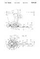
- FIG. 1is a front elevational view of a first embodiment of a direct cardiac pumping mechanism provided with gel-filled contact pads in accordance with the invention
- FIG. 2is a separate front view of a part of the pumping mechanism shown in FIG. 1, illustrating first and second operating positions;
- FIG. 3is a top view as seen along the line 3--3 in FIG. 1;
- FIG. 4is an enlarged elevational view of a gel-filled contact pad in accordance with the invention, as viewed along the line 4--4 in FIG. 1;
- FIG. 5is an end view as seen along the line 5--5 in FIG. 4;
- FIG. 6is a side view as seen along the line 6--6 in FIG. 4;
- FIG. 7is a further enlarged cross-sectional view, as seen along the line 7--7 in FIG. 4;
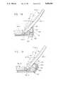
- FIG. 8is a front elevational, cross-sectional view of a second embodiment of a direct cardiac pumping mechanism in accordance with the invention, with certain parts omitted, taken essentially along the line 8--8 in FIG. 9;
- FIG. 9is a top view as seen along the line 9--9 in FIG. 8;
- FIG. 10is a schematic diagram of a ventricular assist device comprising a third embodiment of a direct cardiac pumping mechanism in accordance with the invention, shown implanted in a patient's body;
- FIG. 11is a front elevational view, with certain parts omitted, of the pumping mechanism shown in FIG. 10;
- FIG. 12is a top view as seen along the line 12--12 in FIG. 11;
- FIG. 13is a bottom view as seen along the line 13--13 in FIG. 11;
- FIG. 14is a schematic diagram of the pumping mechanism shown in FIG. 10;
- FIG. 15is a cross-sectional view of a generator-type energy converter of the pumping mechanism shown in FIG. 10.
- FIG. 16is a front elevational view, partially in cross-section and with certain parts omitted, of a fourth embodiment of a direct cardiac pumping mechanism in accordance with the invention.
- FIG. 17is a top view as seen along the line 17--17 in FIG. 16;
- FIG. 18is an enlarged cross-sectional view of a portion of the pumping mechanism shown in FIG. 16;
- FIG. 19is a cross-sectional view similar to FIG. 18, showing an alternate arrangement
- FIG. 20is an enlarged cross-sectional view taken along the line 20--20 in FIG. 16;
- FIG. 21is a block diagram of a closed loop fluid recovery system which may be used in the embodiment of the invention shown in FIGS. 16-20;
- FIG. 22-27are schematic views illustrating the structure and operation of the fluid recovery system shown in FIG. 21.
- FIGS. 1-3illustrate a left ventricle 12 of a heart 14 in conjunction with a direct cardiac pumping or compression mechanism 20 of a type disclosed in FIGS. 4a, b and c of U.S. patent application Ser. No. 07/019,701, filed Feb. 27, 1987, in the names of Marlin S. Heilman and Steve A. Kolenik, entitled "Biocompatible Ventricular Assist and Arrhythmia Control Device", and assigned to the same Assignee as the subject application, with like parts in FIGS. 1-3 being identified by the same reference numbers as in that application.
- the direct cardiac pumping mechanism 20comprises a part of an implantable subsystem of a biocompatible ventricular assist and arrhythmia control device 10, the remainder of which is not shown, but which is described in detail in the aforementioned patent application, the disclosure of which, to the extent not inconsistent with this disclosure, is hereby incorporated by reference.
- the direct cardiac pumping mechanism 20differs from the corresponding mechanism in the aforementioned patent application in being provided with a plurality of gel-filled contact pads 22 on pressure plates 120, for directly engaging the heart ventricle 12 in a uniform manner, so as to prevent damage to the ventricle, particularly at the edges of the pressure plates, and for other purposes, as is subsequently described herein.
- the pumping mechanismincludes triaxial lateral pressure plate or compression assemblies 118 for engaging and compressing the heart left ventricle 12 in synchronism with native or pacemaker-initiated pumping action, or a synchronously during ventricle fibrillation.
- Each pressure plate assembly 118includes one of the pressure plates 120, each of which is formed of a spring-tempered, biocompatible, inert metal, such as the nickel alloy MP35NR (an alloy of nickel, cobalt, chromium, and molybdenum).
- Each pressure plate 120is attached to a driver arm 122 or 124 by way of an axle/bearing mount 126 so that the pressure plate may follow, within specified limits, an actual movement of the heart.
- Each driver arm 122 or 124is mounted on an actuator housing 128 (FIGS. 1 and 3), being pivoted on a light-weight, high-performance bearing 130, which, like the bearing in the axial/bearing mount 126, may consist of a tubular lining of woven TEFLON (polytetraflouroethylene)/DACRON (polyester) fabric and an inner wound fiberglass epoxy resin matrix.
- the driver arms 122 and 124 and the actuator housing 128each is formed of a biocompatible metal compound, such as Ti6A14V (titanium, aluminum, and vanadium).
- Driver arms 122 and 124are engaged by wedge followers 132, each of which includes a roller 134 mounted on a follower bearing 136 (of similar construction to arm bearing 130).
- the above pumping or compression mechanism 20is readily adapted to varying combinations of pressure plate assemblies 118.
- triaxial lateral placementcould be supplemented with a fourth, smaller plate (not shown) positioned on the heart right ventricle (not shown), or with an apical plate (not shown) for supporting and supplying compressive force to the apex of the left heart ventricle 12.
- the pumping mechanism 20can be modified.
- the pressure platescan be made larger (e.g., wider) and their number reduced, or made smaller (e.g., thinner) and their number increased, as shown in FIGS. 8-20. Additional pumping mechanism arrangements are disclosed in the aforementioned U.S patent application Ser. No. 07/019,701.
- the pressure plate assemblies 118are movable between solid line positions, as shown in FIGS. 1-3, when the left ventricle 12 expands (diastole), and broken line positions (FIGS. 2 and 3) when the left ventricle contracts (systole). Operation of the pressure plate assemblies 118 to compress the left ventricle 12 is accomplished by a biocompatible fluid, such as mineral oil, flowing through a connection tube 182 from a rotary-to-axial drive-converting mechanism (not shown), as disclosed in the abovementioned U.S. patent application Ser. No. 07/019,701, into a bellows 184 in the actuator housing 128, to cause expansion of the bellows, to which is welded a driving wedge 186. In turn, the wedge 186 exerts lateral pressure on the wedge followers 132, which then cause the pressure plate assemblies 118 to pivot on the arm bearings 130 and compress the left ventricle 12 simultaneously.
- a biocompatible fluidsuch as mineral oil
- the gel-filled contact pad 22has a generally concave configuration so as to be adapted to conform uniformly to the surface of the left ventricle 12, so that applied force by the pad is distributed uniformly over the ventricle's surface.
- the periphery of the gel-filled contact pad 22also extends outward beyond the periphery of the associated pressure plate 120, to preclude damage to the left ventricle by pressure exerted from the peripheral edges of the plate, including damaging cardiac muscle or the coronary arteries, or interfering with the muscle's blood supply.
- the gel-filled contact pad 22includes a molded hollow sheath or body member 24 formed of a soft, electrically insulating material having a specific gravity and stiffness similar to that of human muscle tissue (i.e., the left ventricle 12), such as a polyurethane elastomer, so as to be adapted to be easily deformed, thereby reducing the possibility of pressure points occurring on the ventricle's surface, and preventing localized cardiac tissue damage.
- the sheath 24, and thus the pad 22,preferably is filled with a soft gel 26 (FIG. 7), such as a polyurethane or silicon gel.
- the sheath 24also preferably has a relatively thin wall thickness in a range on the order of 5-13 mils.
- the sheath 24 of the gel-filled contact pad 22also has opposite sides each having an undulating surface formed by intersecting rows of three dimensional, curvilinear surfaces, in the form of raised dimples 28 molded into the pad surface and having a height in a range on the order of 32 mils, so that each side of the pad has a dimpled or pebbled configuration.
- the raised dimples 28facilitate shrinkage and expansion of the surface of the gel-filled contact pad 22 with the left ventricle 12 in three dimensions as it expands and contracts in its operation. This allows the surface of the left ventricle 12 to shrink and expand naturally, without undue strain.
- the dimples 28also offer a secondary benefit in that they reduce the stress level in the outer layer of the gel-filled contact pad 22.
- selected ones of the raised dimples 28 on the side of the gel-filled contact pad sheath 24 facing its associated pressure plate 120may be bonded or glued to the plate by an adhesive 30 consisting of an electrically insulating material, such as a silicone rubber or a thermoplastic, while other ones of the dimples may be left unbonded to permit flexibility of movement of the sheath 24 relative to the pressure plate in response to expansion and contraction of the left ventricle 12.
- the tops of selected ones of the dimples 28 on the opposite side of the sheath 24 engaging the left ventricle -2may be bonded or glued to the ventricle by a similar adhesive 32.
- FIGS. 4 and 7Other selected ones of the raised dimples 28 on the ventricle-engaging side of the sheath 24 may be provided with small islands 34 (FIGS. 4 and 7) of a material, such as DACRON (polyester), for promoting tissue growth between the gel-filled contact pad 22 and the left ventricle 12.
- the gel-filled contact pad 22also may be sutured to the left ventricle 12, as for example, by projecting tabs 36 integrally molded with the sheath 24, for example, to selected ones of the dimples 28 at opposite edges of the sheath, as illustrated in FIGS. 4-7.
- the tissue growth-producing islands 34, adhesive 32 and the suturing tabs 36cooperate to firmly anchor the gel-filled contact pad 22 to the left ventricle 12.
- the gel-filled contact pad 22also includes an electrode 38 (best shown in FIGS. 4 and 7) for transmitting heart signals from the left ventricle 12, and/or for applying control signals, such as cardioverting/defibrillating pulses, to the ventricle.
- the electrode 38is in the form of a rectangular grid formed, for example, of a titanium wire mesh and including, as viewed in FIG. 4, intersecting horizontal strips 38h and vertical strips 38v, which define dimple-receiving openings 38o (FIG. 4) therebetween.
- the strips 38h and 38vare bonded, such as by adhesive 40 (shown only in FIG.
- the thickness of the mesh forming the electrode 38is slightly less than the height of the raised dimples 28, (e.g., 20 mils) such that when the gel-filled contact pad 22 is engaged with the left ventricle 12, as illustrated in FIGS. 5, 6 and 7, the dimples can compress slightly, with the electrode wire mesh coming into direct engagement with the ventricle.
- the electrode 38is connected to a control unit (not shown), which includes a cardioverter/defibrillator unit, as disclosed in the abovementioned U.S. patent application Ser. No. 07/019,701, by suitable electrical conductors 44 (shown only in FIG. 4) extending from one end of the electrode to an electrical conductor conduit or cable 188 (FIG. 1) bonded to the actuator housing 28.
- a control unitnot shown
- a cardioverter/defibrillator unitas disclosed in the abovementioned U.S. patent application Ser. No. 07/019,701, by suitable electrical conductors 44 (shown only in FIG. 4) extending from one end of the electrode to an electrical conductor conduit or cable 188 (FIG. 1) bonded to the actuator housing 28.
- the gel-filled contact pads 22also are advantageous in that they can be placed over bypass grafts with no significant deleterious reduction in blood flow in the grafts, because of the soft nature of the pads and because pumping assistance force to the left ventricle 12 is only applied during cardiac systole when coronary blood flow is minimal. In this connection, most coronary blood flow occurs during cardiac diastole when the gel-filled contact pads 22 are not applying force to the surface of the left ventricle 12.
- the second embodiment of the invention showncomprises a pumping or compression mechanism 20-2 which includes six pressure plate or compression assemblies 118-2 (all shown only in FIG. 9) each having an elongated pressure plate or finger 120-2 provided with a gel-filled compression pad 22-2, which may be of the same construction as shown in FIGS. 4-7, for applying pressure to a left ventricle 12-2 of a heart 14-2.
- a forked lower end of each pressure plate 120-2is pivotally mounted on a lug portion 44 of a central support member, such as a hub 46, by a pivot pin 130-2.
- the support hub 46includes a depending central shaft 48 fixedly secured at its lower end in a suitable manner (not shown) to one end of an elongated base member 50 which has a small reversible drive motor 52 and a speed reducer 54 mounted thereon adjacent an opposite end, for operating a cam mechanism 56.
- each of the pressure plate assemblies 118-2is movable by the cam mechanism 56 from a solid line retracted position to a dashed line position in a ventricle compressing operation.
- the cam mechanism 56includes an essentially annular, vertically movable first camming plate 58 encircling the central support hub 46 and mounted with eight radially extending arms 60, each having a tapered camming surface 62.
- six of the camming surfaces 62engage respective camming rollers 64 on respective ones of the pressure plates 120-2 of the pressure plate assemblies 118-2 so that vertical movement of the camming plate 58 moves the pressure plate assemblies to their ventricle compressing positions.
- Located between selected ones of the camming arms 60are at least three (four being shown) coil springs 66, which are disposed between vertically spaced projecting upper and lower arms 68 on the support hub 46 and the camming plate 58, respectively, to produce balanced return of the cam mechanism 56 to an initial lower position.
- additional ones of the pressure plate assemblies 118-2also may be provided on the support hub 46 for operation by the remaining two camming arms 60, to also provide additional compression of the left ventricle 12, or compression of a right ventricle, depending upon the position of the pressure plate assemblies on the heart.
- first camming plate 58Vertical movement of the first camming plate 58 is accomplished by a plurality of circumferentially spaced, tapered cam segments 70 mounted on a second camming plate 72 supported for rotation on the depending shaft 48 of the support hub 46 by suitable bearings 74.
- An upper end of each of the tapered cam segments 70is disposed in a correspondingly tapered groove 76 in a bottom wall of a respective one of the radially extending camming arms 60, so that rotation of the second camming plate 72 causes raising of the first camming plate 58 and movement of the pressure plate assemblies 118-2 to their broken line positions during a ventricle compression operation.
- the rotatable second camming plate 72is rotated clockwise for this purpose by the reversible drive motor 52 and the speed reducer 54, through a drive shaft 78 journaled at its left-hand end in a bearing 80 on the base member 50 and having a pinion gear 82 engaged with a radially outward extending toothed segment 84 of the rotatable second camming plate 72.
- the rotatable camming plate 72is rotated in a reverse direction (counter clockwise in FIG. 9) to permit the downward movement of the vertically movable first camming plate 58, and thus movement of the pressure plate assemblies 118-2 back to their solid line positions, during a ventricle filling operation.
- FIGS. 10-15illustrate a third embodiment of the invention in which a biocompatible ventricular assist device 10-3 comprises a pumping or compression mechanism 20-3 which includes eight pressure plate or compression assemblies 118-3 (all shown only in FIGS. 12 and 13) and an electrical-to-fluid energy converter 86 operated from an electronic control module 88 comprising an electrical power source and control circuitry, neither of which is shown.
- the pumping mechanism 20-3is positionable on a left ventricle 12-3 of a heart 14-3 as illustrated in FIG. 10 and is connected to the energy converter 86 by a pressurized hydraulic fluid hose 90 and a low compliance fluid hose 92, shown generally in FIG. 10 and more specifically in FIGS. 14 and 15.
- the energy converter 86is connected to the electronic control module 88 by a cable 94 formed of electrical wires 96, as illustrated generally in FIG. 10.
- the eight pressure plate assemblies 118-3include respective pressure plates or fingers 120-3 which surround the left heart ventricle 12-3 and which are provided with gel-filled compression pads 22-3.
- Lower ends of the pressure plates 120-3are pivotally mounted by pivot pins 130-3 (FIG. 11) on a central support member, in this instance a horizontally disposed, circular support plate 46-3 fixedly secured to upper ends of vertically extending support posts 100 having lower ends fixedly secured to a horizontally disposed base plate 102.
- the pressure plate assemblies 118-3 which are disposed around the exterior of the heart left ventricle 12-3are longer than the pressure plate assemblies on the opposite side of the heart 14-3 adjacent a heart right ventricle.
- the left-hand pressure plates 120-3may be of two-part construction, comprising an inner base portion 120-3a and an outer portion 120-2b secured together by suitable connectors, e.g.; small bolts, screws or rivets, for "customizing" the length of these plates to the size of the heart involved.
- suitable connectorse.g.; small bolts, screws or rivets
- the base plate 102forms respective lower ends of a pair of metal bellows 104 having upper ends defined by a movable top plate 106, with the base plate and top plate being interconnected by expandable-and-contractible metal bellows portions 108 having opposite ends welded to the base plate and the top plate, respectively.
- the bellows top plate 106has a plurality of upstanding pressure plate operating members 110 having lower ends fixed to the top plate, with their upper ends provided with camming rollers 134-3 engageable with respective ones of the pressure plates 120-3.
- both bellowsexpand and cause the top plate 106, and thus the operating members 110 and the camming rollers 134-3, to move upward to move the pressure plate assemblies 118-3 from their solid line positions to ventricle compressing dashed line positions, as shown in FIG. 11.
- the pressure plate assemblies 118-3can return to their solid line positions to permit expansion of the heart ventricle 12-3.
- the energy converter 86converts electrical energy into pressurized hydraulic fluid energy, to operate the pumping mechanism 20-3.
- the energy converter 86includes a small reversible, brushless DC servomotor 112 (FIG. 15).
- a drive shaft 114 of the motor 112operates a gerotor pump 116, with the drive shaft extending through an opening in a pump housing 138 and having an impeller 140 of the pump fixed on an outer end of the shaft within the housing.
- Opposite ends of the drive shaft 114are supported in bearings 142 fixedly mounted to a wall of a sealed metal casing 144 filled with a hydraulic fluid 146.
- Power for the drive motor 112is provided by a plurality of the wires 96, which extend through an opening in an end wall of the sealed casing 144 from the electronic control module 88.
- the energy converter 86further comprises a normally closed electrical solenoid valve 148 of low power design connected in parallel with the pump, as illustrated in FIG. 14, and a welded metal compliance bellows 150 disposed within the hydraulic fluid 146 in the sealed casing 144 and movable between an expanded solid line position and a compressed dashed line position, as shown in FIG. 15.
- the low compliance hose 92which is connected to the left-hand end of the sealed casing 144, as viewed in FIG. 15, extends to the right adjacent the bellows 150 and is connected to a fixed right-hand end thereof, as viewed in this figure.
- the lower portion of the pumping mechanism 20-3is enclosed within a covering or casing 152 of a flexible fluid-impervious material, such as polyurethane elastomer, suitably sealed or bonded to the associated parts of the pumping mechanism to define a leakproof container.
- a covering or casing 152 of a flexible fluid-impervious materialsuch as polyurethane elastomer
- the interior of the covering 152 and the interior of the metal bellows 150 in the energy converter casing 144are filled with a hydraulic fluid 154 to define a closed fluid system.
- the servomotor 112 and the spring-loaded solenoid valve 148are energized from an electrical power source (not shown) in the electronic control module 88 to drive the gerotor pump 116 and close the solenoid valve 148, respectively, causing four events to occur simultaneously.
- the gerotor pump 116draws in fluid 146 from within the sealed casing 144 and pressurizes the fluid.
- the gerotor pump 116also ejects the pressurized fluid 146 through a fluid passage 156 with sufficient pressure so that the fluid flows through the pressurized fluid hose 90 into the bellows 104 of the pumping mechanism 20-3, causing the bellows to expand and move the pressure plate assemblies 118-3 into compressing relationship with the left heart ventricle 12-3.
- the compliance bellows 150 in the sealed casingexpands from a dashed line position to a solid line position in FIG. 15, to prevent a vacuum from being formed in the sealed casing.
- the normally closed solenoid valve 148will automatically open with fluid flow being reversed and bypassing the pump 116 in essentially the same manner so that the pressure plate assemblies 118-3 automatically are de-coupled from the heart 14-4.
- FIGS. 16-20disclose a fourth embodiment of the invention in which a ventricular assist device 10-4 comprises a pumping or compression mechanism 20-4 also having eight pressure plate or compression assemblies 118-4, each including a compression plate 120-4 in the form of an elongated "finger” or “paddle", which encompass a heart -4-4.
- a compression plate 120-4in the form of an elongated "finger” or “paddle", which encompass a heart -4-4.
- lower ends of the compression plates 120-4are pivotally mounted on a central support member, in this instance an octagonal mounting hub 46-4, by pivot pins 130-4.
- a hard surface coatingsuch as a diamond film (not shown), produced by ion-implantation and/or chemical vapor deposition, may be applied to pivot surfaces of both the pressure plates 120-4 and the pivot pins 130-4.
- the pumping mechanism 20-4uses a miniature hydraulic actuator 158 to pivot each pressure plate assembly 118-4 inward.
- the hydraulic actuators 158are integrally formed as parts of a hydraulic fluid manifold 160, also of octagonal construction, and connected to a suitable hydraulic fluid supply 144' via a pump 116' and a pressurized fluid hose 90'.
- Each actuator 158includes a cylinder 162 having a cylinder wall 162w formed in a peripheral portion 164 of the manifold in fluid communication with an interior of the manifold, and a miniature piston 166 (e.g., on the order of 0.187 inch in diameter) disposed for reciprocating movement in the cylinder wall.
- each piston 166is adapted to slidably engage its associated compression plate 120-4 for pivoting the compression plate inward in a ventricle compressing operation, but is otherwise disconnected from the compression plate, to provide a "decoupling" feature to the pumping mechanism 20-4, by allowing the pressure plate assemblies 118-4 to float freely with the heart 14-4 when the pistons are stationary.
- each piston 166which has a circular cross section, may be in the form of a partial toroid with a curvature along a circumferentially extending axis and having, by way of example, a radius on the order of 0.400 inch.
- the associated cylinder wall 162wis of the same arcuate configuration, with the piston 166 mounted for sliding movement in the cylinder wall along an arcuate path, with the shape of the cylinder wall precisely matching that of the piston.
- a titanium alloyhaving a hard surface coating, also may be used to form the cylinder wall 162w.
- an actuator 158' having a cylinder 162' with a cylinder wall 162w' and a piston 166' arranged in a conventional straight-line arrangement as shown in FIG. 19,may be used, with this arrangement requiring that a manifold 160' be slightly larger than the manifold 160 shown in FIGS. 16 and 18.
- sealing of the hydraulic fluid against flow around the piston 166may be accomplished by one or more miniature metallic rings 168 secured to the piston by being disposed in a respective small annular groove in the piston, such as in an automobile engine.
- the cross-section of the cylinder wall 162wmust be perfectly circular at all points, to provide uniform contact between the metallic ring(s) 168 and the cylinder wall.
- an elastomeric piston seal(not shown) may be used in place of the metallic ring 168, as for example, a seal made of a composite material having a TEFLON (polytetraflouroethylene) base.
- each of the pressure plate assemblies 118-4comprises a gel-filled contact pad 22-4 mounted on a pressure plate or finger 120-4.
- a heart ventricle engaging surface of the contact pad 22-4is provided with a layer of a soft, open-cell urethane foam 170 for making direct contact with the surface of a heart ventricle 12-4.
- the open structure of the urethane foam 170also promotes the ingrowth of heart ventricle tissue to the contact pad 22-4, which includes a sheath 24-4 formed of a bio-compatible urethane elastomer, while the inside of the pad is filled with a soft elastomer gel 26-4.
- An inner support surface of the contact pad 22-4which is suitably bonded to an inner surface of the pressure plate 120-4, is of smooth construction, while the surface of the pad adjacent the heart ventricle 12-4 and having the layer of urethane foam 170 thereon, is of a convoluted construction (corrugations or dimples) to allow the pad to easily shrink and expand as the size of the heart ventricle 12-4 changes.
- the layer of urethane foam 170 which fills the spaces between the convolutions of the convoluted surfacealso shrinks and expands without interfering with the shrinkage and expansion of the heart surface.
- FIG. 21illustrates diagrammatically a closed loop system 172 for collecting and reusing hydraulic fluid which may leak from the hydraulic actuators 158 or 158' past the metallic rings (or elastomer seals) 168 or 168 of the pistons 166 or 166'.
- the system 172comprises a fluid leakage collector, which may be, for example, in the form of a covering or casing 152, for the lower portion of the pumping mechanism 20-4, such as the covering 152 in the embodiment of the invention shown in FIGS. 10-15.
- the collector 152'captures any hydraulic fluid which may leak from the actuators 158 or 158', with the fluid draining back through a compliance hose 92' to a fluid supply casing 144' containing a pump 116', for operating the actuators 158 or 158' through a pressurized hydraulic fluid hose 90, and the manifolds 46-4 or 46-4', respectively.
- FIG. 22is a schematic view illustrating the closed loop fluid recovery system 172 in conjunction with one of the miniature actuators 158'.
- the pump 116'is in the form of a piston 173 disposed in a cylinder 174 and having a connecting rod 175 reciprocated by a lead screw 176 driven by a small reversible motor 177.
- This entire assemblyis located in the fluid supply sealed casing 144', which is filled with hydraulic fluid 146', and the cylinder 174 includes a small intake opening 178 in a side wall thereof.
- the cylinder 174also is connected by the pressurized hydraulic line 90' to the manifold 46-4', and thus to each of the actuators 158', with the manifold and the actuators being encased, along with lower portions of the compression plate assemblies 120-4, in the sealed covering 152', which is connected to the fluid supply casing 144' by the compliance hydraulic line 92'.
- the fluidmerely escapes from the high pressure cylinder 162' of the actuator into the lower pressure covering 152', and flows back to the fluid supply casing 144', without any fluid being lost from the system 172.
- the gel-filled contact pad 22is mounted on a pressure plate 120 of a cardiac compression assembly 20, for engaging an outer surface of at least one heart ventricle, such as the left ventricle 12, with the outer periphery of the gel-filled contact pad extending outward beyond the outer periphery of the pressure plate to preclude damage to the ventricle, particularly by the peripheral edges of the pressure plate.
- the gel-filled contact pad 22has a generally concave configuration so as to be adapted to conform uniformly to the left ventricle 12, so that applied force by the pad is distributed uniformly over the ventricle's surface.
- the contact pad sheath 24has an undulating surface on its opposite sides, formed by the raised dimples 28, to facilitate shrinkage and expansion of the contact pad with the left ventricle 12, so that the ventricle can shrink and expand naturally, without undue strain and without being damaged.
- the raised dimples 28also facilitate securing of the contact pad to the pressure plate 120 and the left ventricle 12.
- selected ones of the raised dimples 28may be glued to the left ventricle 12, and other ones of the dimples may be provided with the tissue growth-producing islands 34, for securing the contact pad to the ventricle.
- the 20also may include the tissue growth-promoting porous urethane elastomer foam 170.
- the gel-filled contact pad 22also may readily be sutured to the left ventricle 12 by the integrally formed suturing tabs 36.
- the raised dimples 28form depressed portions or valleys 42 for receiving the grid-type, wire mesh electrode 38, for transmitting heart signals from the left ventricle 12, and/or applying control signals, such as cardioverting/defibrillating pulses, to the ventricle.
- Other improved forms of the cardiac ventricular assist device 10, including various improved pumping or compression mechanisms 20,also have been disclosed in FIGS. 8-21.
Landscapes
- Health & Medical Sciences (AREA)
- Engineering & Computer Science (AREA)
- Heart & Thoracic Surgery (AREA)
- Cardiology (AREA)
- Biomedical Technology (AREA)
- Anesthesiology (AREA)
- Mechanical Engineering (AREA)
- Hematology (AREA)
- Life Sciences & Earth Sciences (AREA)
- Animal Behavior & Ethology (AREA)
- General Health & Medical Sciences (AREA)
- Public Health (AREA)
- Veterinary Medicine (AREA)
- Vascular Medicine (AREA)
- External Artificial Organs (AREA)
Abstract
Description
Claims (103)
Priority Applications (1)
| Application Number | Priority Date | Filing Date | Title |
|---|---|---|---|
| US07/522,956US5098369A (en) | 1987-02-27 | 1990-05-14 | Biocompatible ventricular assist and arrhythmia control device including cardiac compression pad and compression assembly |
Applications Claiming Priority (2)
| Application Number | Priority Date | Filing Date | Title |
|---|---|---|---|
| US07/019,701US4925443A (en) | 1987-02-27 | 1987-02-27 | Biocompatible ventricular assist and arrhythmia control device |
| US07/522,956US5098369A (en) | 1987-02-27 | 1990-05-14 | Biocompatible ventricular assist and arrhythmia control device including cardiac compression pad and compression assembly |
Related Parent Applications (1)
| Application Number | Title | Priority Date | Filing Date |
|---|---|---|---|
| US07/019,701Continuation-In-PartUS4925443A (en) | 1987-02-27 | 1987-02-27 | Biocompatible ventricular assist and arrhythmia control device |
Publications (1)
| Publication Number | Publication Date |
|---|---|
| US5098369Atrue US5098369A (en) | 1992-03-24 |
Family
ID=26692510
Family Applications (1)
| Application Number | Title | Priority Date | Filing Date |
|---|---|---|---|
| US07/522,956Expired - Fee RelatedUS5098369A (en) | 1987-02-27 | 1990-05-14 | Biocompatible ventricular assist and arrhythmia control device including cardiac compression pad and compression assembly |
Country Status (1)
| Country | Link |
|---|---|
| US (1) | US5098369A (en) |
Cited By (189)
| Publication number | Priority date | Publication date | Assignee | Title |
|---|---|---|---|---|
| EP0617981A1 (en)* | 1993-03-29 | 1994-10-05 | Pacesetter AB | Mechanical defibrillation |
| US5383840A (en)* | 1992-07-28 | 1995-01-24 | Vascor, Inc. | Biocompatible ventricular assist and arrhythmia control device including cardiac compression band-stay-pad assembly |
| US5562595A (en)* | 1995-08-17 | 1996-10-08 | Medtronic, Inc. | Multiple therapy cardiac assist device having battery voltage safety monitor |
| US5658237A (en)* | 1995-08-17 | 1997-08-19 | Medtronic, Inc. | Cardiac assist device having improved muscle stimulation |
| US5697952A (en)* | 1995-08-17 | 1997-12-16 | Medtronic, Inc. | Cardiac assist device having muscle augementation after confirmed arrhythmia and method |
| US5697884A (en)* | 1995-08-17 | 1997-12-16 | Medtronic, Inc. | Cardiac assist device having circadian muscle simulation |
| US5707336A (en)* | 1995-01-09 | 1998-01-13 | Cardassist Incorporated | Ventricular assist device |
| US5713954A (en)* | 1995-06-13 | 1998-02-03 | Abiomed R&D, Inc. | Extra cardiac ventricular assist device |
| US5716379A (en)* | 1995-08-17 | 1998-02-10 | Medtronic, Inc. | Cardiac assist device having muscle augmentation prior to defibrillation |
| US5800528A (en)* | 1995-06-13 | 1998-09-01 | Abiomed R & D, Inc. | Passive girdle for heart ventricle for therapeutic aid to patients having ventricular dilatation |
| US5888186A (en)* | 1995-07-27 | 1999-03-30 | Allegheny-Singer Research Institute | Muscle energy converter activated assist system and method |
| US5894843A (en)* | 1996-02-20 | 1999-04-20 | Cardiothoracic Systems, Inc. | Surgical method for stabilizing the beating heart during coronary artery bypass graft surgery |
| EP0711577A3 (en)* | 1994-11-08 | 1999-04-21 | Telectronics N.V. | An improved cardio myostimulation system with defibrillation |
| US5910124A (en)* | 1994-01-10 | 1999-06-08 | Cardiassist Incorporated | Ventricular assist device and method |
| US6036641A (en)* | 1996-02-20 | 2000-03-14 | Cardiothoracic System, Inc. | Surgical instruments for stabilizing the beating heart during coronary artery bypass graft surgery |
| US6066106A (en)* | 1998-05-29 | 2000-05-23 | Emergency Medical Systems, Inc. | Modular CPR assist device |
| US6090056A (en)* | 1997-08-27 | 2000-07-18 | Emergency Medical Systems, Inc. | Resuscitation and alert system |
| US6110098A (en)* | 1996-12-18 | 2000-08-29 | Medtronic, Inc. | System and method of mechanical treatment of cardiac fibrillation |
| EP1007112A4 (en)* | 1997-06-06 | 2000-09-13 | John C Woodard | Cardiac assist device |
| US6142962A (en)* | 1997-08-27 | 2000-11-07 | Emergency Medical Systems, Inc. | Resuscitation device having a motor driven belt to constrict/compress the chest |
| WO2000078375A1 (en)* | 1999-06-17 | 2000-12-28 | Heart Assist Technologies Pty Ltd. | An assist device for the failing heart |
| US6168634B1 (en) | 1999-03-25 | 2001-01-02 | Geoffrey W. Schmitz | Hydraulically energized magnetorheological replicant muscle tissue and a system and a method for using and controlling same |
| US6213960B1 (en) | 1998-06-19 | 2001-04-10 | Revivant Corporation | Chest compression device with electro-stimulation |
| US6231506B1 (en) | 1999-05-04 | 2001-05-15 | Cardiothoracic Systems, Inc. | Method and apparatus for creating a working opening through an incision |
| US6238334B1 (en) | 1997-11-03 | 2001-05-29 | Cardio Technologies, Inc. | Method and apparatus for assisting a heart to pump blood |
| US6254525B1 (en) | 1998-11-04 | 2001-07-03 | Cardio Technologies, Inc. | Cardiac assist system and method thereof |
| US6258023B1 (en) | 1999-07-08 | 2001-07-10 | Chase Medical, Inc. | Device and method for isolating a surface of a beating heart during surgery |
| US6283912B1 (en) | 1999-05-04 | 2001-09-04 | Cardiothoracic Systems, Inc. | Surgical retractor platform blade apparatus |
| US6290644B1 (en) | 1996-02-20 | 2001-09-18 | Cardiothoracic Systems, Inc. | Surgical instruments and procedures for stabilizing a localized portion of a beating heart |
| US6328688B1 (en) | 1995-09-20 | 2001-12-11 | Medtronic, Inc. | Method and apparatus for temporarily immobilizing a local area of tissue |
| US6338712B2 (en)* | 1997-09-17 | 2002-01-15 | Origin Medsystems, Inc. | Device to permit offpump beating heart coronary bypass surgery |
| US20020019580A1 (en)* | 2000-03-10 | 2002-02-14 | Lilip Lau | Expandable cardiac harness for treating congestive heart failure |
| US6348036B1 (en) | 1999-01-24 | 2002-02-19 | Genzyme Corporation | Surgical retractor and tissue stabilization device |
| US6361493B1 (en) | 1997-09-17 | 2002-03-26 | Origin Medsystems, Inc. | Device to permit offpump beating heart coronary bypass surgery |
| US6390976B1 (en) | 1997-09-17 | 2002-05-21 | Origin Medsystems, Inc. | System to permit offpump beating heart coronary bypass surgery |
| US6406424B1 (en) | 1999-09-16 | 2002-06-18 | Williamson, Iv Warren P. | Tissue stabilizer having an articulating lift element |
| US6432039B1 (en) | 1998-12-21 | 2002-08-13 | Corset, Inc. | Methods and apparatus for reinforcement of the heart ventricles |
| US6447465B1 (en) | 1998-11-10 | 2002-09-10 | Revivant Corporation | CPR device with counterpulsion mechanism |
| US6464629B1 (en) | 1998-09-15 | 2002-10-15 | Medtronic, Inc. | Method and apparatus for temporarily immobilizing a local area of tissue |
| US6464655B1 (en)* | 1999-03-17 | 2002-10-15 | Environmental Robots, Inc. | Electrically-controllable multi-fingered resilient heart compression devices |
| AU754198B2 (en)* | 1997-06-06 | 2002-11-07 | William J Seare Jr | Cardiac assist device |
| US20030004445A1 (en)* | 2001-05-25 | 2003-01-02 | Revivant Corporation | CPR compression device and method |
| US6506149B2 (en) | 1999-09-07 | 2003-01-14 | Origin Medsystems, Inc. | Organ manipulator having suction member supported with freedom to move relative to its support |
| US20030011256A1 (en)* | 2001-06-07 | 2003-01-16 | Matsushita Electric Industrial Co., Ltd. | Hydrodynamic gas bearing |
| US6511416B1 (en) | 1999-08-03 | 2003-01-28 | Cardiothoracic Systems, Inc. | Tissue stabilizer and methods of use |
| US6540659B1 (en) | 2000-11-28 | 2003-04-01 | Abiomed, Inc. | Cardiac assistance systems having bi-directional pumping elements |
| US6547716B1 (en) | 2000-11-28 | 2003-04-15 | Abiomed, Inc. | Passive cardiac restraint systems having multiple layers of inflatable elements |
| US6565582B2 (en) | 1995-02-24 | 2003-05-20 | Hearport, Inc. | Devices and methods for performing a vascular anastomosis |
| US20030094180A1 (en)* | 1995-04-10 | 2003-05-22 | Benetti Frederico J. | Method for coronary artery bypass |
| US6572534B1 (en) | 2000-09-14 | 2003-06-03 | Abiomed, Inc. | System and method for implanting a cardiac wrap |
| US6602182B1 (en) | 2000-11-28 | 2003-08-05 | Abiomed, Inc. | Cardiac assistance systems having multiple fluid plenums |
| US20030153949A1 (en)* | 2001-10-31 | 2003-08-14 | Lilip Lau | Heart failure treatment device and method |
| US6612978B2 (en) | 1999-12-22 | 2003-09-02 | Paracor Surgical, Inc. | Expandable cardiac harness for treating congestive heart failure |
| US6616620B2 (en) | 2001-05-25 | 2003-09-09 | Revivant Corporation | CPR assist device with pressure bladder feedback |
| US6616596B1 (en) | 2000-11-28 | 2003-09-09 | Abiomed, Inc. | Cardiac assistance systems having multiple layers of inflatable elements |
| US6626830B1 (en) | 1999-05-04 | 2003-09-30 | Cardiothoracic Systems, Inc. | Methods and devices for improved tissue stabilization |
| US6626821B1 (en) | 2001-05-22 | 2003-09-30 | Abiomed, Inc. | Flow-balanced cardiac wrap |
| US6676597B2 (en) | 2001-01-13 | 2004-01-13 | Medtronic, Inc. | Method and device for organ positioning |
| US6685632B1 (en) | 1999-05-04 | 2004-02-03 | Cardiothoracic Systems, Inc. | Surgical instruments for accessing and stabilizing a localized portion of a beating heart |
| US6695769B2 (en) | 2001-09-25 | 2004-02-24 | The Foundry, Inc. | Passive ventricular support devices and methods of using them |
| US6709382B1 (en) | 1999-05-04 | 2004-03-23 | Simon Marcus Horner | Cardiac assist method and apparatus |
| US20040064014A1 (en)* | 2001-05-31 | 2004-04-01 | Melvin David B. | Devices and methods for assisting natural heart function |
| US6730022B2 (en) | 1999-01-24 | 2004-05-04 | Thomas E. Martin | Surgical retractor and tissue stabilization device having an adjustable sled member |
| US20040106871A1 (en)* | 2001-02-23 | 2004-06-03 | Hunyor Stephen Nicholas | Determining the volume of a normal heart and its pathological and treated variants by using dimension sensors |
| US6758808B2 (en) | 2001-01-24 | 2004-07-06 | Cardiothoracic System, Inc. | Surgical instruments for stabilizing a localized portion of a beating heart |
| US20040138522A1 (en)* | 2002-08-21 | 2004-07-15 | Haarstad Philip J. | Methods and apparatus providing suction-assisted tissue engagement through a minimally invasive incision |
| US20040143156A1 (en)* | 2001-09-10 | 2004-07-22 | Lilip Lau | Device for treating heart failure |
| US20040162587A1 (en)* | 2003-02-14 | 2004-08-19 | Medtronic Physio-Control Corp. | Cooperating defibrillators and external chest compression devices |
| US20040162510A1 (en)* | 2003-02-14 | 2004-08-19 | Medtronic Physio-Control Corp | Integrated external chest compression and defibrillation devices and methods of operation |
| US20040167375A1 (en)* | 2003-02-25 | 2004-08-26 | Couvillon Lucien A. | Cardiac assist device with electroactive polymers |
| US20040210104A1 (en)* | 2002-11-15 | 2004-10-21 | Lilip Lau | Cardiac harness delivery device and method |
| US6808483B1 (en) | 2000-10-03 | 2004-10-26 | Paul A. Spence | Implantable heart assist devices and methods |
| US20040249242A1 (en)* | 2003-03-28 | 2004-12-09 | Lilip Lau | Multi-panel cardiac harness |
| US20040267086A1 (en)* | 2003-06-26 | 2004-12-30 | Anstadt Mark P. | Sensor-equipped and algorithm-controlled direct mechanical ventricular assist device |
| US20050010197A1 (en)* | 2003-07-08 | 2005-01-13 | Liming Lau | Organ manipulator apparatus |
| US6846296B1 (en) | 2000-09-14 | 2005-01-25 | Abiomed, Inc. | Apparatus and method for detachably securing a device to a natural heart |
| US6852075B1 (en) | 1996-02-20 | 2005-02-08 | Cardiothoracic Systems, Inc. | Surgical devices for imposing a negative pressure to stabilize cardiac tissue during surgery |
| US20050038475A1 (en)* | 2003-02-18 | 2005-02-17 | Medtronic Physio-Control Corp. | Defibrillators learning of other concurrent therapy |
| US20050043657A1 (en)* | 2003-08-21 | 2005-02-24 | Scimed Life Systems, Inc. | External counterpulsation device using electroactive polymer actuators |
| US20050054892A1 (en)* | 2003-07-10 | 2005-03-10 | Lilip Lau | Self-anchoring cardiac harness |
| US20050059855A1 (en)* | 2002-11-15 | 2005-03-17 | Lilip Lau | Cardiac harness delivery device and method |
| US20050102010A1 (en)* | 2003-11-07 | 2005-05-12 | Lilip Lau | Cardiac harness for treating congestive heart failure and for defibrillating and/or pacing/sensing |
| US20050102013A1 (en)* | 2003-11-07 | 2005-05-12 | Lilip Lau | Cardiac harness for treating heart disease |
| US20050137673A1 (en)* | 2003-11-07 | 2005-06-23 | Lilip Lau | Cardiac harness having electrodes and epicardial leads |
| US20050148822A1 (en)* | 2003-12-30 | 2005-07-07 | Willis Geoffrey H. | Organ manipulator and positioner and methods of using the same |
| US20050148825A1 (en)* | 1997-09-17 | 2005-07-07 | Spence Paul A. | Device to permit offpump beating heart coronary bypass surgery |
| US20050148824A1 (en)* | 2003-12-30 | 2005-07-07 | Morejohn Dwight P. | Transabdominal surgery system |
| US20050154253A1 (en)* | 2004-01-12 | 2005-07-14 | Lilip Lau | Cardiac harness having interconnected strands |
| US20050171589A1 (en)* | 2003-11-07 | 2005-08-04 | Lilip Lau | Cardiac harness and method of delivery by minimally invasive access |
| US20050256368A1 (en)* | 2002-11-15 | 2005-11-17 | Paracor Medical, Inc. | Introducer for a cardiac harness delivery |
| US20050283042A1 (en)* | 2003-03-28 | 2005-12-22 | Steve Meyer | Cardiac harness having radiopaque coating and method of use |
| US20060009675A1 (en)* | 2004-07-08 | 2006-01-12 | Steven Meyer | Self-anchoring cardiac harness for treating the heart and for defibrillating and/or pacing/sensing |
| US7060023B2 (en) | 2001-09-25 | 2006-06-13 | The Foundry Inc. | Pericardium reinforcing devices and methods of using them |
| US20060129026A1 (en)* | 2004-12-15 | 2006-06-15 | Joshua Wallin | Apparatus and method for mounting a cardiac harness on the heart |
| US20070015959A1 (en)* | 2000-02-14 | 2007-01-18 | Obtech Medical Ag | Male impotence prosthesis apparatus with wireless energy supply |
| US20070027516A1 (en)* | 2005-08-01 | 2007-02-01 | Alan Schaer | Cardiac harness having an optimal impedance range |
| US20070032696A1 (en)* | 2005-07-22 | 2007-02-08 | Sieu Duong | Cardiac harness delivery device |
| US20070055091A1 (en)* | 2004-12-02 | 2007-03-08 | Lilip Lau | Cardiac harness for treating congestive heart failure and for defibrillating and/or pacing/sensing |
| US7189201B2 (en) | 1995-09-20 | 2007-03-13 | Medtronic, Inc. | Method and apparatus for temporarily immobilizing a local area of tissue |
| US20070088203A1 (en)* | 2005-05-25 | 2007-04-19 | Liming Lau | Surgical assemblies and methods for visualizing and performing surgical procedures in reduced-access surgical sites |
| US20070106359A1 (en)* | 2003-11-07 | 2007-05-10 | Alan Schaer | Cardiac harness assembly for treating congestive heart failure and for pacing/sensing |
| US20070106336A1 (en)* | 2003-11-07 | 2007-05-10 | Alan Schaer | Cardiac harness assembly for treating congestive heart failure and for pacing/sensing |
| US7229405B2 (en) | 2002-11-15 | 2007-06-12 | Paracor Medical, Inc. | Cardiac harness delivery device and method of use |
| WO2007066344A1 (en)* | 2005-12-07 | 2007-06-14 | Baskaran Chandrasekar | Implantable extra-cardiac compression device for left ventricular assistance in severe heart failure |
| US20070145281A1 (en)* | 2005-12-13 | 2007-06-28 | Shlomo Ben-Haim | Lens System For Nuclear Medicine Gamma Ray Camera |
| US20070185369A1 (en)* | 2006-02-03 | 2007-08-09 | Mahmood Mirhoseini | Cardiac assist device and method |
| US20070255093A1 (en)* | 2002-11-15 | 2007-11-01 | Lilip Lau | Cardiac harness delivery device and method |
| US20070287883A1 (en)* | 2006-06-07 | 2007-12-13 | Lilip Lau | Apparatus and method for pulling a cardiac harness onto a heart |
| US7338434B1 (en) | 2002-08-21 | 2008-03-04 | Medtronic, Inc. | Method and system for organ positioning and stabilization |
| US20080064917A1 (en)* | 2003-10-15 | 2008-03-13 | Eli Bar | Amplification-Based Cardiac Assist Device |
| US7399272B2 (en) | 2004-03-24 | 2008-07-15 | Medtronic, Inc. | Methods and apparatus providing suction-assisted tissue engagement |
| US20080275296A1 (en)* | 2000-02-10 | 2008-11-06 | Obtech Medical Ag | Mechanical impotence treatment apparatus |
| US7485089B2 (en) | 2002-09-05 | 2009-02-03 | Paracor Medical, Inc. | Cardiac harness |
| US20090048480A1 (en)* | 2007-08-13 | 2009-02-19 | Paracor Medical, Inc. | Cardiac harness delivery device |
| WO2009048397A1 (en)* | 2007-10-11 | 2009-04-16 | Milux Holding Sa | Method for assisting flow in a heart |
| WO2009048377A1 (en)* | 2007-10-11 | 2009-04-16 | Milux Holding Sa | Method for assisting flow in a heart |
| US20090177028A1 (en)* | 2008-01-04 | 2009-07-09 | Anthony John White | Non-blood contact cardiac compression device, for augmentation of cardiac function by timed cyclic tensioning of elastic cords in an epicardial location |
| US20090281372A1 (en)* | 2008-05-06 | 2009-11-12 | Paracor Medical, Inc. | Cardiac harness assembly for treating congestive heart failure and for defibrillation and/or pacing/sensing |
| WO2010042013A1 (en)* | 2008-10-10 | 2010-04-15 | Milux Holding Sa | Heart help device, system, and method |
| WO2010042014A1 (en)* | 2008-10-10 | 2010-04-15 | Milux Holding Sa | Heart help device, system, and method |
| WO2010042016A1 (en)* | 2008-10-10 | 2010-04-15 | Milux Holding Sa | Heart help device, system, and method |
| US20100145139A1 (en)* | 2000-02-10 | 2010-06-10 | Obtech Medical Ag | Controlled urinary incontinence treatment |
| US20100145138A1 (en)* | 2000-02-10 | 2010-06-10 | Obtech Medical Ag | Urinary incontinence treatment with wireless energy supply |
| US20100152523A1 (en)* | 2005-11-28 | 2010-06-17 | Myocardiocare, Inc. | Method and Apparatus for Minimally Invasive Direct Mechanical Ventricular Actuation |
| US7794387B2 (en) | 2006-04-26 | 2010-09-14 | Medtronic, Inc. | Methods and devices for stabilizing tissue |
| US20100312164A1 (en)* | 2008-01-28 | 2010-12-09 | Peter Forsell | Implantable drainage device |
| US20100332000A1 (en)* | 2008-01-29 | 2010-12-30 | Peter Forsell | Device for treating obesity |
| US20110015473A1 (en)* | 2009-07-17 | 2011-01-20 | Teslux Holdings S.A. | Vaginal operation method for the treatment of urinary incontinence in women |
| US20110040143A1 (en)* | 2000-02-11 | 2011-02-17 | Obtech Medical Ag | Impotence treatment apparatus with energy transforming means |
| US7931590B2 (en) | 2002-10-29 | 2011-04-26 | Maquet Cardiovascular Llc | Tissue stabilizer and methods of using the same |
| US20110118829A1 (en)* | 2009-11-15 | 2011-05-19 | Thoratec Corporation | Attachment device and method |
| US20110118833A1 (en)* | 2009-11-15 | 2011-05-19 | Thoratec Corporation | Attachment device and method |
| US20110160850A1 (en)* | 2009-12-30 | 2011-06-30 | Thoratec Corporation | Blood Pump System With Mounting Cuff |
| US7976454B2 (en) | 2002-01-07 | 2011-07-12 | Paracor Medical, Inc. | Cardiac harness |
| US20110196189A1 (en)* | 2010-02-09 | 2011-08-11 | Myocardiocare, Inc. | Extra-cardiac differential ventricular actuation by inertial and baric partitioning |
| US20110196192A1 (en)* | 2008-10-10 | 2011-08-11 | Milux Holding S.A. | Heart help device, system, and method |
| US20110196486A1 (en)* | 2008-10-10 | 2011-08-11 | Milux Holdings SA | Heart help device, system, and method |
| US20110202041A1 (en)* | 2008-10-10 | 2011-08-18 | Milux Holding Sa | Fastening means for implantable medical control assembly |
| US8083664B2 (en) | 2005-05-25 | 2011-12-27 | Maquet Cardiovascular Llc | Surgical stabilizers and methods for use in reduced-access surgical sites |
| US8096938B2 (en) | 1999-08-12 | 2012-01-17 | Obtech Medical Ag | Controlled anal incontinence disease treatment |
| US8126558B2 (en) | 2000-02-14 | 2012-02-28 | Obtech Medical Ag | Controlled penile prosthesis |
| US8192351B2 (en) | 2007-08-13 | 2012-06-05 | Paracor Medical, Inc. | Medical device delivery system having integrated introducer |
| US8313423B2 (en) | 2000-02-14 | 2012-11-20 | Peter Forsell | Hydraulic anal incontinence treatment |
| WO2013102465A1 (en)* | 2012-01-05 | 2013-07-11 | Ibrahim Mostafa Mohamed Ibrahim | Artificial heart pump |
| US8545384B2 (en) | 1999-08-12 | 2013-10-01 | Obtech Medical Ag | Anal incontinence disease treatment with controlled wireless energy supply |
| US8600510B2 (en) | 2008-10-10 | 2013-12-03 | Milux Holding Sa | Apparatus, system and operation method for the treatment of female sexual dysfunction |
| US8734318B2 (en) | 2000-02-11 | 2014-05-27 | Obtech Medical Ag | Mechanical anal incontinence |
| US8764627B2 (en) | 2000-02-14 | 2014-07-01 | Obtech Medical Ag | Penile prosthesis |
| US8795150B2 (en) | 2008-10-10 | 2014-08-05 | Milux Holding S.A. | Heart help device, system, and method |
| US8874215B2 (en) | 2008-10-10 | 2014-10-28 | Peter Forsell | System, an apparatus, and a method for treating a sexual dysfunctional female patient |
| US9022998B2 (en) | 2010-02-26 | 2015-05-05 | Maquet Cardiovascular Llc | Blower instrument, apparatus and methods of using |
| WO2015051380A3 (en)* | 2013-10-04 | 2015-06-11 | President And Fellows Of Harvard College | Biomimetic actuation device and system, and methods for controlling a biomimetic actuation device and system |
| US9107800B2 (en) | 2002-03-21 | 2015-08-18 | Physio-Control, Inc. | Front part for support structure for CPR |
| US9138228B2 (en) | 2004-08-11 | 2015-09-22 | Emory University | Vascular conduit device and system for implanting |
| US9144637B2 (en) | 2011-03-02 | 2015-09-29 | Thoratec Corporation | Ventricular cuff |
| US9149412B2 (en) | 2012-06-14 | 2015-10-06 | Zoll Medical Corporation | Human powered mechanical CPR device with optimized waveform characteristics |
| US9199019B2 (en) | 2012-08-31 | 2015-12-01 | Thoratec Corporation | Ventricular cuff |
| US9308015B2 (en) | 2007-04-24 | 2016-04-12 | Emory University | Conduit device and system for implanting a conduit device in a tissue wall |
| US9320875B2 (en) | 2011-02-01 | 2016-04-26 | Emory University | Systems for implanting and using a conduit within a tissue wall |
| US9532773B2 (en) | 2011-01-28 | 2017-01-03 | Apica Cardiovascular Limited | Systems for sealing a tissue wall puncture |
| US9655605B2 (en) | 2010-06-14 | 2017-05-23 | Maquet Cardiovascular Llc | Surgical instruments, systems and methods of use |
| WO2017087754A3 (en)* | 2015-11-18 | 2017-08-17 | President And Fellows Of Harvard College | Compositions and methods of mechanically inducing tissue regeneration |
| CN107206139A (en)* | 2014-11-17 | 2017-09-26 | 雷内·佐兹 | Device and system for strengthening heart |
| US9949812B2 (en) | 2009-07-17 | 2018-04-24 | Peter Forsell | Vaginal operation method for the treatment of anal incontinence in women |
| US9981076B2 (en) | 2012-03-02 | 2018-05-29 | Tc1 Llc | Ventricular cuff |
| US10004662B2 (en) | 2014-06-06 | 2018-06-26 | Physio-Control, Inc. | Adjustable piston |
| US10028741B2 (en) | 2013-01-25 | 2018-07-24 | Apica Cardiovascular Limited | Systems and methods for percutaneous access, stabilization and closure of organs |
| US10092464B2 (en) | 2014-10-03 | 2018-10-09 | Physio-Control, Inc. | Medical device stabilization strap |
| US10219898B2 (en) | 2008-10-10 | 2019-03-05 | Peter Forsell | Artificial valve |
| US10485909B2 (en) | 2014-10-31 | 2019-11-26 | Thoratec Corporation | Apical connectors and instruments for use in a heart wall |
| US10518012B2 (en) | 2013-03-15 | 2019-12-31 | Apk Advanced Medical Technologies, Inc. | Devices, systems, and methods for implanting and using a connector in a tissue wall |
| CN111067667A (en)* | 2019-12-27 | 2020-04-28 | 先健科技(深圳)有限公司 | Force measuring device and its push assembly |
| US10639234B2 (en) | 2015-10-16 | 2020-05-05 | Zoll Circulation, Inc. | Automated chest compression device |
| US10682282B2 (en) | 2015-10-16 | 2020-06-16 | Zoll Circulation, Inc. | Automated chest compression device |
| US10874583B2 (en) | 2017-04-20 | 2020-12-29 | Zoll Circulation, Inc. | Compression belt assembly for a chest compression device |
| US10894116B2 (en) | 2016-08-22 | 2021-01-19 | Tc1 Llc | Heart pump cuff |
| US10905629B2 (en) | 2018-03-30 | 2021-02-02 | Zoll Circulation, Inc. | CPR compression device with cooling system and battery removal detection |
| US11235137B2 (en) | 2017-02-24 | 2022-02-01 | Tc1 Llc | Minimally invasive methods and devices for ventricular assist device implantation |
| US11246795B2 (en) | 2017-04-20 | 2022-02-15 | Zoll Circulation, Inc. | Compression belt assembly for a chest compression device |
| US11246796B2 (en) | 2014-06-06 | 2022-02-15 | Physio-Control, Inc. | Adjustable piston |
| US11383076B2 (en) | 2020-10-01 | 2022-07-12 | Lifebridge Technologies, Llc | Pump regulation based on heart size and function |
| CN115087481A (en)* | 2020-02-04 | 2022-09-20 | W.L.戈尔及同仁股份有限公司 | Inflow/outflow cannula |
| WO2022194981A1 (en)* | 2021-03-17 | 2022-09-22 | Universite De Lorraine | Device for assistance by direct cardiac compression |
| CN113975623B (en)* | 2021-09-27 | 2023-10-31 | 江苏大学 | Novel negative pressure non-contact heart pump |
| US11896812B1 (en) | 2023-01-27 | 2024-02-13 | Lifebridge Technologies Llc | Versatile modular heart pump for non-blood contacting ventricular function augmentation |
| US12011516B2 (en) | 2016-06-17 | 2024-06-18 | Cornell University | Foam actuators |
| US12115363B1 (en) | 2023-08-10 | 2024-10-15 | Lifebridge Technologies Llc | System and method for introducing a construct either on or around the surface of the heart |
| US12263332B2 (en) | 2022-09-13 | 2025-04-01 | Lifebridge Technologies Llc | Material characteristics ideal for providing either partial or total mechanical support to the failing or arrested heart and method for developing ideal characteristics for underlying cardiac disorders |
| US12440338B2 (en) | 2023-12-05 | 2025-10-14 | Lifebridge Technologies Llc | Minimally invasive heart pump with modular adjustable construct insertion |
Citations (4)
| Publication number | Priority date | Publication date | Assignee | Title |
|---|---|---|---|---|
| US4192293A (en)* | 1978-09-05 | 1980-03-11 | Manfred Asrican | Cardiac assist device |
| US4536893A (en)* | 1982-03-03 | 1985-08-27 | Roberto Parravicini | Implant device for substaining the activity of the myocardium |
| US4928674A (en)* | 1988-11-21 | 1990-05-29 | The Johns Hopkins University | Cardiopulmonary resuscitation and assisted circulation system |
| US4957477A (en)* | 1986-05-22 | 1990-09-18 | Astra Tech Ab | Heart assist jacket and method of using it |
- 1990
- 1990-05-14USUS07/522,956patent/US5098369A/ennot_activeExpired - Fee Related
Patent Citations (4)
| Publication number | Priority date | Publication date | Assignee | Title |
|---|---|---|---|---|
| US4192293A (en)* | 1978-09-05 | 1980-03-11 | Manfred Asrican | Cardiac assist device |
| US4536893A (en)* | 1982-03-03 | 1985-08-27 | Roberto Parravicini | Implant device for substaining the activity of the myocardium |
| US4957477A (en)* | 1986-05-22 | 1990-09-18 | Astra Tech Ab | Heart assist jacket and method of using it |
| US4928674A (en)* | 1988-11-21 | 1990-05-29 | The Johns Hopkins University | Cardiopulmonary resuscitation and assisted circulation system |
Cited By (483)
| Publication number | Priority date | Publication date | Assignee | Title |
|---|---|---|---|---|
| US5383840A (en)* | 1992-07-28 | 1995-01-24 | Vascor, Inc. | Biocompatible ventricular assist and arrhythmia control device including cardiac compression band-stay-pad assembly |
| US5433731A (en)* | 1993-03-29 | 1995-07-18 | Pacesetter Ab | Mechanical defibrillator and method for defibrillating a heart |
| EP0617981A1 (en)* | 1993-03-29 | 1994-10-05 | Pacesetter AB | Mechanical defibrillation |
| US5910124A (en)* | 1994-01-10 | 1999-06-08 | Cardiassist Incorporated | Ventricular assist device and method |
| EP0711577A3 (en)* | 1994-11-08 | 1999-04-21 | Telectronics N.V. | An improved cardio myostimulation system with defibrillation |
| US5707336A (en)* | 1995-01-09 | 1998-01-13 | Cardassist Incorporated | Ventricular assist device |
| US6699257B2 (en) | 1995-02-24 | 2004-03-02 | Heartport, Inc | Devices and methods for performing a vascular anastomosis |
| US6565582B2 (en) | 1995-02-24 | 2003-05-20 | Hearport, Inc. | Devices and methods for performing a vascular anastomosis |
| US7219671B2 (en) | 1995-04-10 | 2007-05-22 | Cardiothoracic Systems, Inc. | Method for coronary artery bypass |
| US20030094180A1 (en)* | 1995-04-10 | 2003-05-22 | Benetti Frederico J. | Method for coronary artery bypass |
| US5800528A (en)* | 1995-06-13 | 1998-09-01 | Abiomed R & D, Inc. | Passive girdle for heart ventricle for therapeutic aid to patients having ventricular dilatation |
| US5713954A (en)* | 1995-06-13 | 1998-02-03 | Abiomed R&D, Inc. | Extra cardiac ventricular assist device |
| US6508756B1 (en) | 1995-06-13 | 2003-01-21 | Abiomed, Inc. | Passive cardiac assistance device |
| US6224540B1 (en) | 1995-06-13 | 2001-05-01 | Abiomed, Inc. | Passive girdle for heart ventricle for therapeutic aid to patients having ventricular dilatation |
| US5888186A (en)* | 1995-07-27 | 1999-03-30 | Allegheny-Singer Research Institute | Muscle energy converter activated assist system and method |
| US5716379A (en)* | 1995-08-17 | 1998-02-10 | Medtronic, Inc. | Cardiac assist device having muscle augmentation prior to defibrillation |
| US5697884A (en)* | 1995-08-17 | 1997-12-16 | Medtronic, Inc. | Cardiac assist device having circadian muscle simulation |
| US5697952A (en)* | 1995-08-17 | 1997-12-16 | Medtronic, Inc. | Cardiac assist device having muscle augementation after confirmed arrhythmia and method |
| US5658237A (en)* | 1995-08-17 | 1997-08-19 | Medtronic, Inc. | Cardiac assist device having improved muscle stimulation |
| US5562595A (en)* | 1995-08-17 | 1996-10-08 | Medtronic, Inc. | Multiple therapy cardiac assist device having battery voltage safety monitor |
| US6464630B1 (en) | 1995-09-20 | 2002-10-15 | Medtronic, Inc. | Method and apparatus for temporarily immobilizing a local area of tissue |
| US6394948B1 (en) | 1995-09-20 | 2002-05-28 | Medtronic, Inc. | Method and apparatus for temporarily immobilizing a local area of tissue |
| US6371906B1 (en) | 1995-09-20 | 2002-04-16 | Medtronic, Inc. | Method and apparatus for temporarily immobilizing a local area of tissue |
| US6364826B1 (en) | 1995-09-20 | 2002-04-02 | Medtronic, Inc. | Method and apparatus for temporarily immobilizing a local area of tissue |
| US6755780B2 (en) | 1995-09-20 | 2004-06-29 | Medtronic, Inc. | Method and apparatus for temporarily immobilizing a local area of tissue |
| US7189201B2 (en) | 1995-09-20 | 2007-03-13 | Medtronic, Inc. | Method and apparatus for temporarily immobilizing a local area of tissue |
| US7611455B2 (en) | 1995-09-20 | 2009-11-03 | Medtronic, Inc. | Method and apparatus for temporarily immobilizing a local area of tissue |
| US7445594B1 (en) | 1995-09-20 | 2008-11-04 | Medtronic, Inc. | Method and apparatus for temporarily immobilizing a local area of tissue |
| US7048683B2 (en) | 1995-09-20 | 2006-05-23 | Medtronic, Inc. | Method and apparatus for temporarily immobilizing a local area of tissue |
| US6350229B1 (en) | 1995-09-20 | 2002-02-26 | Medtronic, Inc. | Method and apparatus for temporarily immobilizing a local area of tissue |
| US20060036128A1 (en)* | 1995-09-20 | 2006-02-16 | Medtronic, Inc. | Method and apparatus for temporarily immobilizing a local area of tissue |
| US6336898B1 (en) | 1995-09-20 | 2002-01-08 | Medtronic, Inc. | Method and apparatus for temporarily immobilizing a local area of tissue |
| US6328688B1 (en) | 1995-09-20 | 2001-12-11 | Medtronic, Inc. | Method and apparatus for temporarily immobilizing a local area of tissue |
| US6334843B1 (en) | 1995-09-20 | 2002-01-01 | Medtronic, Inc. | Method and apparatus for temporarily immobilizing a local area of tissue |
| US6290644B1 (en) | 1996-02-20 | 2001-09-18 | Cardiothoracic Systems, Inc. | Surgical instruments and procedures for stabilizing a localized portion of a beating heart |
| US6394951B1 (en) | 1996-02-20 | 2002-05-28 | Cardiothoracic Systems, Inc. | Surgical instruments and procedures for stabilizing the beating heart during coronary artery bypass graft surgery |
| US6315717B1 (en) | 1996-02-20 | 2001-11-13 | Cardiothoracic Systems, Inc. | Surgical instruments for stabilizing the beating heart during coronary artery bypass graft surgery |
| US20070149844A1 (en)* | 1996-02-20 | 2007-06-28 | Benetti Federico J | Surgical devices for imposing a negative pressure to stabilize the cardiac tissue during surgery |
| US6852075B1 (en) | 1996-02-20 | 2005-02-08 | Cardiothoracic Systems, Inc. | Surgical devices for imposing a negative pressure to stabilize cardiac tissue during surgery |
| US7335158B2 (en) | 1996-02-20 | 2008-02-26 | Cardiothoracic Systems, Inc. | Surgical devices for imposing a negative pressure to stabilize the cardiac tissue during surgery |
| US6346077B1 (en) | 1996-02-20 | 2002-02-12 | Cardiothoracic Systems, Inc. | Surgical instrument for stabilizing the beating heart during coronary artery bypass graft surgery |
| US20040230099A1 (en)* | 1996-02-20 | 2004-11-18 | Taylor Charles S. | Surgical instruments and procedures for stabilizing the beating heart during coronary artery bypass graft surgery |
| US20080114201A1 (en)* | 1996-02-20 | 2008-05-15 | Taylor Charles S | Surgical devices for imposing a negative pressure to stabilize the cardiac tissue during surgery |
| US20050033111A1 (en)* | 1996-02-20 | 2005-02-10 | Taylor Charles S. | Surgical devices for imposing a negative pressure to stabilize cardiac tissue during surgery |
| US20050038316A1 (en)* | 1996-02-20 | 2005-02-17 | Taylor Charles S. | Surgical devices for imposing a negative pressure to stabilize cardiac tissue during surgery |
| US6213941B1 (en) | 1996-02-20 | 2001-04-10 | Cardiothoracic Systems, Inc. | Surgical instruments for stabilizing the beating heart during coronary bypass graft surgery |
| US20070055108A1 (en)* | 1996-02-20 | 2007-03-08 | Taylor Charles S | Surgical instruments and procedures for stabilizing the beating heart during coronary artery bypass graft surgery |
| US6893391B2 (en) | 1996-02-20 | 2005-05-17 | Cardiothoracic Systems, Inc. | Surgical devices for imposing a negative pressure to stabilize cardiac tissue during surgery |
| US7485090B2 (en) | 1996-02-20 | 2009-02-03 | Maquet Cardiovascular Llc | Surgical devices for imposing a negative pressure to stabilize cardiac tissue during surgery |
| US8382654B2 (en) | 1996-02-20 | 2013-02-26 | Maquet Cardiovascular Llc | Surgical devices for imposing a negative pressure to stabilize the cardiac tissue during surgery |
| US7056287B2 (en) | 1996-02-20 | 2006-06-06 | Cardiothoracic Systems, Inc. | Surgical instruments and procedures for stabilizing the beating heart during coronary artery bypass graft surgery |
| US7497824B2 (en) | 1996-02-20 | 2009-03-03 | Maquet Cardiovasculer, Llc | Surgical devices for imposing a negative pressure to stabilize cardiac tissue during surgery |
| US6743169B1 (en) | 1996-02-20 | 2004-06-01 | Cardiothoracic Systems, Inc. | Surgical instruments and procedures for stabilizing the beating heart during coronary artery bypass graft surgery |
| US6701930B2 (en) | 1996-02-20 | 2004-03-09 | Cardiothoracic Systems, Inc. | Surgical instruments and procedures for stabilizing the beating heart during coronary artery bypass graft surgery |
| US5894843A (en)* | 1996-02-20 | 1999-04-20 | Cardiothoracic Systems, Inc. | Surgical method for stabilizing the beating heart during coronary artery bypass graft surgery |
| US20020111537A1 (en)* | 1996-02-20 | 2002-08-15 | Taylor Charles S. | Surgical instruments and procedures for stabilizing the beating heart during coronary artery bypass graft surgery |
| US7585277B2 (en) | 1996-02-20 | 2009-09-08 | Maquet Cardiovascular Llc | Surgical instruments and procedures for stabilizing the beating heart during coronary artery bypass graft surgery |
| US6036641A (en)* | 1996-02-20 | 2000-03-14 | Cardiothoracic System, Inc. | Surgical instruments for stabilizing the beating heart during coronary artery bypass graft surgery |
| US6656113B2 (en) | 1996-02-20 | 2003-12-02 | Cardiothoracic System, Inc. | Surgical instruments and procedures for stabilizing a localized portion of a beating heart |
| US6050266A (en)* | 1996-02-20 | 2000-04-18 | Cardiothracic Systems, Inc. | Procedures for stabilizing the beating heart during coronary artery bypass graft surgery |
| US20110172568A1 (en)* | 1996-02-20 | 2011-07-14 | Taylor Charles S | Surgical Devices for Imposing a Negative Pressure to Stabilize the Cardiac Tissue During Surgery |
| US8277476B2 (en)* | 1996-02-20 | 2012-10-02 | Maguet Cardiovascular LLC | Surgical instruments and procedures for stabilizing the beating heart during coronary artery bypass graft |
| US6110098A (en)* | 1996-12-18 | 2000-08-29 | Medtronic, Inc. | System and method of mechanical treatment of cardiac fibrillation |
| US6330475B1 (en) | 1996-12-18 | 2001-12-11 | Medtronic Inc. | System and a corresponding method for treating defibrillation in a heart |
| AU754198B2 (en)* | 1997-06-06 | 2002-11-07 | William J Seare Jr | Cardiac assist device |
| EP1007112A4 (en)* | 1997-06-06 | 2000-09-13 | John C Woodard | Cardiac assist device |
| US7442173B1 (en) | 1997-08-27 | 2008-10-28 | Zoll Circulation, Inc. | Resuscitation device with friction liner |
| US6090056A (en)* | 1997-08-27 | 2000-07-18 | Emergency Medical Systems, Inc. | Resuscitation and alert system |
| US6926682B2 (en) | 1997-08-27 | 2005-08-09 | Revivant Corporation | Resuscitation device |
| US20050273023A1 (en)* | 1997-08-27 | 2005-12-08 | Revivant Corporation | Resuscitation device with expert system |
| US20130317398A1 (en)* | 1997-08-27 | 2013-11-28 | Zoll Circulation, Inc. | Resuscitation Device with Expert System |
| US9241867B2 (en)* | 1997-08-27 | 2016-01-26 | Zoll Circulation, Inc. | Resuscitation device with expert system |
| US20040215112A1 (en)* | 1997-08-27 | 2004-10-28 | Revivant Corporation | Resuscitation device and method |
| US20040073145A1 (en)* | 1997-08-27 | 2004-04-15 | Revivant Corporation | Resuscitation device |
| US8868180B2 (en)* | 1997-08-27 | 2014-10-21 | Zoll Circulation, Inc. | Resuscitation device with expert system |
| US8224442B2 (en)* | 1997-08-27 | 2012-07-17 | Zoll Circulation, Inc. | Resuscitation device with expert system |
| US6599258B1 (en) | 1997-08-27 | 2003-07-29 | Revivant Corporation | Resuscitation device |
| US20150051522A1 (en)* | 1997-08-27 | 2015-02-19 | Zoll Circulation, Inc. | Resuscitation Device with Expert System |
| US7517326B2 (en) | 1997-08-27 | 2009-04-14 | Zoll Circulation, Inc. | Resuscitation device including a belt cartridge |
| US20060264789A1 (en)* | 1997-08-27 | 2006-11-23 | Mollenauer Kenneth H | Resuscitation device and method |
| US7077814B2 (en) | 1997-08-27 | 2006-07-18 | Zoll Circulation, Inc. | Resuscitation method using a sensed biological parameter |
| US20110282408A1 (en)* | 1997-08-27 | 2011-11-17 | Zoll Circulation, Inc. | Resuscitation Device with Expert System |
| US7996081B2 (en) | 1997-08-27 | 2011-08-09 | Zoll Circulation, Inc. | Resuscitation device with expert system |
| US6142962A (en)* | 1997-08-27 | 2000-11-07 | Emergency Medical Systems, Inc. | Resuscitation device having a motor driven belt to constrict/compress the chest |
| US6743170B1 (en) | 1997-09-17 | 2004-06-01 | Cardiothoracic Systems, Inc. | Device to permit offpump beating heart coronary bypass surgery |
| US7476196B2 (en) | 1997-09-17 | 2009-01-13 | Maquet Cardiovascular, Llc | Device to permit offpump beating heart coronary bypass surgery |
| US20020161285A1 (en)* | 1997-09-17 | 2002-10-31 | Spence Paul A. | Device to permit offpump beating heart coronary bypass surgery |
| US7377895B2 (en) | 1997-09-17 | 2008-05-27 | Origin Medsystems, Inc. | Device to permit offpump beating heart coronary bypass surgery |
| US6610008B1 (en) | 1997-09-17 | 2003-08-26 | Origin Medsystems, Inc. | Device and method to permit offpump beating heart coronary bypass surgery |
| US7404792B2 (en) | 1997-09-17 | 2008-07-29 | Origin Medsystems, Inc. | Device to permit offpump beating heart coronary bypass surgery |
| US6969349B1 (en) | 1997-09-17 | 2005-11-29 | Origin Medsystem, Inc. | Device to permit offpump beating heart coronary bypass surgery |
| US8317695B2 (en) | 1997-09-17 | 2012-11-27 | Maquet Cardiovascular Llc | Device to permit offpump beating heart coronary bypass surgery |
| US7476199B2 (en) | 1997-09-17 | 2009-01-13 | Maquet Cardiovascular, Llc. | Device to permit offpump beating heart coronary bypass surgery |
| US20090099412A1 (en)* | 1997-09-17 | 2009-04-16 | Spence Paul A | Device to Permit Offpump Beating Heart Coronary Bypass Surgery |
| US7195591B2 (en) | 1997-09-17 | 2007-03-27 | Origin Medsystems, Inc. | Device to permit offpump beating heart coronary bypass surgery |
| US20040138533A1 (en)* | 1997-09-17 | 2004-07-15 | Spence Paul A. | Device to permit offpump beating heart coronary bypass surgery |
| US20090099411A1 (en)* | 1997-09-17 | 2009-04-16 | Spence Paul A | Device to permit offpump beating heart coronary bypass surgery |
| US6361493B1 (en) | 1997-09-17 | 2002-03-26 | Origin Medsystems, Inc. | Device to permit offpump beating heart coronary bypass surgery |
| US6390976B1 (en) | 1997-09-17 | 2002-05-21 | Origin Medsystems, Inc. | System to permit offpump beating heart coronary bypass surgery |
| US20020065451A1 (en)* | 1997-09-17 | 2002-05-30 | Spence Paul A. | Device to permit offpump beating heart coronary bypass surgery |
| US8162817B2 (en) | 1997-09-17 | 2012-04-24 | Maquet Cardiovascular Llc | Device to permit offpump beating heart coronary bypass surgery |
| US6705988B2 (en) | 1997-09-17 | 2004-03-16 | Origin Medsystems, Inc. | Device to permit offpump beating heart coronary bypass surgery |
| US20050148825A1 (en)* | 1997-09-17 | 2005-07-07 | Spence Paul A. | Device to permit offpump beating heart coronary bypass surgery |
| US20040225195A1 (en)* | 1997-09-17 | 2004-11-11 | Spence Paul A. | Device to permit offpump beating heart coronary bypass surgery |
| US6338712B2 (en)* | 1997-09-17 | 2002-01-15 | Origin Medsystems, Inc. | Device to permit offpump beating heart coronary bypass surgery |
| US8753266B2 (en) | 1997-09-17 | 2014-06-17 | Maquet Cardiovascular Llc | Device to permit offpump beating heart coronary bypass surgery |
| US6726622B2 (en) | 1997-09-17 | 2004-04-27 | Origin Medsystems, Inc. | Device to permit offpump beating heart coronary bypass surgery |
| US20040092798A1 (en)* | 1997-09-17 | 2004-05-13 | Spence Paul A. | Device to permit offpump beating heart coronary bypass surgery |
| US20070179344A1 (en)* | 1997-09-17 | 2007-08-02 | Spence Paul A | Device to permit offpump beating heart coronary bypass surgery |
| US6238334B1 (en) | 1997-11-03 | 2001-05-29 | Cardio Technologies, Inc. | Method and apparatus for assisting a heart to pump blood |
| US20080300516A1 (en)* | 1998-05-29 | 2008-12-04 | Zoll Circulation, Inc. | Method of Performing CPR with a Modular CPR Assist Device |
| US7374548B2 (en) | 1998-05-29 | 2008-05-20 | Zoll Circulation, Inc. | Modular CPR assist device to hold at a threshold of tightness |
| US6709410B2 (en) | 1998-05-29 | 2004-03-23 | Revivant Corporation | Modular CPR assist device |
| US8062239B2 (en)* | 1998-05-29 | 2011-11-22 | Zoll Circulation, Inc. | Method of performing CPR with a modular CPR assist device using a brake to momentarily hold a belt at a threshold of tightness |
| US20040193076A1 (en)* | 1998-05-29 | 2004-09-30 | Revivant Corporation | Modular CPR assist device |
| US6398745B1 (en) | 1998-05-29 | 2002-06-04 | Revivant Corporation | Modular CPR assist device |
| US6066106A (en)* | 1998-05-29 | 2000-05-23 | Emergency Medical Systems, Inc. | Modular CPR assist device |
| US20060155222A1 (en)* | 1998-06-19 | 2006-07-13 | Zoll Circulation, Inc. | Chest compression device with electro-stimulation |
| US7011637B2 (en) | 1998-06-19 | 2006-03-14 | Revivant Corporation | Chest compression device with electro-stimulation |
| US7497837B2 (en) | 1998-06-19 | 2009-03-03 | Zoll Circulation, Inc. | Chest compression device with electro-stimulation |
| US6213960B1 (en) | 1998-06-19 | 2001-04-10 | Revivant Corporation | Chest compression device with electro-stimulation |
| US20040039313A1 (en)* | 1998-06-19 | 2004-02-26 | Revivant Corporation | Chest compression device with electro-stimulation |
| US20090177127A1 (en)* | 1998-06-19 | 2009-07-09 | Zoll Circulation, Inc. | Chest Compression Device with Electro-Stimulation |
| US7201716B2 (en) | 1998-09-15 | 2007-04-10 | Medtronic, Inc. | Method and apparatus for temporarily immobilizing a local area of tissue |
| US6464629B1 (en) | 1998-09-15 | 2002-10-15 | Medtronic, Inc. | Method and apparatus for temporarily immobilizing a local area of tissue |
| US20040167549A1 (en)* | 1998-09-15 | 2004-08-26 | Eric Boone | Method and apparatus for temporarily immobilizing a local area of tissue |
| US20070123747A1 (en)* | 1998-09-15 | 2007-05-31 | Eric Boone | Method and apparatus for temporarily immobilizing a local area of tissue |
| US6740028B2 (en) | 1998-09-15 | 2004-05-25 | Medtronic, Inc. | Method and apparatus for temporarily immobilizing a local area of tissue |
| US6254525B1 (en) | 1998-11-04 | 2001-07-03 | Cardio Technologies, Inc. | Cardiac assist system and method thereof |
| US6447465B1 (en) | 1998-11-10 | 2002-09-10 | Revivant Corporation | CPR device with counterpulsion mechanism |
| US20050165335A1 (en)* | 1998-11-10 | 2005-07-28 | Revivant Corporation | CPR device with counterpulsion mechanism |
| US7166082B2 (en) | 1998-11-10 | 2007-01-23 | Zoll Circulation, Inc. | CPR device with counterpulsion mechanism |
| US6869408B2 (en) | 1998-11-10 | 2005-03-22 | Revivant Corporation | CPR device with counterpulsion mechanism |
| US6432039B1 (en) | 1998-12-21 | 2002-08-13 | Corset, Inc. | Methods and apparatus for reinforcement of the heart ventricles |
| US6348036B1 (en) | 1999-01-24 | 2002-02-19 | Genzyme Corporation | Surgical retractor and tissue stabilization device |
| US6730022B2 (en) | 1999-01-24 | 2004-05-04 | Thomas E. Martin | Surgical retractor and tissue stabilization device having an adjustable sled member |
| US20030032855A1 (en)* | 1999-03-17 | 2003-02-13 | Mohsen Shahinpoor | Electrically-controllable multi-fingered resilient heart compression devices |
| US6464655B1 (en)* | 1999-03-17 | 2002-10-15 | Environmental Robots, Inc. | Electrically-controllable multi-fingered resilient heart compression devices |
| US7198594B2 (en)* | 1999-03-17 | 2007-04-03 | Environmental Robots, Inc. | Electrically-controllable multi-fingered resilient heart compression devices |
| US6168634B1 (en) | 1999-03-25 | 2001-01-02 | Geoffrey W. Schmitz | Hydraulically energized magnetorheological replicant muscle tissue and a system and a method for using and controlling same |
| US7238155B2 (en) | 1999-05-04 | 2007-07-03 | Cardiothoracic Systems, Inc. | Method and apparatus for creating a working opening through an incision |
| US20100210916A1 (en)* | 1999-05-04 | 2010-08-19 | Hu Lawrence W | Surgical Instruments for Accessing and Stabilizing a Localized Portion of a Beating Heart |
| US7220228B2 (en) | 1999-05-04 | 2007-05-22 | Cardiothoracic System, Inc. | Surgical retractor blade and system |
| US6626830B1 (en) | 1999-05-04 | 2003-09-30 | Cardiothoracic Systems, Inc. | Methods and devices for improved tissue stabilization |
| US6231506B1 (en) | 1999-05-04 | 2001-05-15 | Cardiothoracic Systems, Inc. | Method and apparatus for creating a working opening through an incision |
| US20040030223A1 (en)* | 1999-05-04 | 2004-02-12 | Calafiore Antonio M. | Method and devices for improved tissue stabilization |
| US6283912B1 (en) | 1999-05-04 | 2001-09-04 | Cardiothoracic Systems, Inc. | Surgical retractor platform blade apparatus |
| US6685632B1 (en) | 1999-05-04 | 2004-02-03 | Cardiothoracic Systems, Inc. | Surgical instruments for accessing and stabilizing a localized portion of a beating heart |
| US9498198B2 (en) | 1999-05-04 | 2016-11-22 | Maquet Cardiovascular, Llc | Surgical instruments for accessing and stabilizing a localized portion of a beating heart |
| US6709382B1 (en) | 1999-05-04 | 2004-03-23 | Simon Marcus Horner | Cardiac assist method and apparatus |
| US20070156027A1 (en)* | 1999-05-04 | 2007-07-05 | Hu Lawrence W | Surgical retractor platform blade apparatus |
| US20020004628A1 (en)* | 1999-05-04 | 2002-01-10 | Hu Lawrence W. | Surgical retractor platform blade apparatus |
| US7736307B2 (en) | 1999-05-04 | 2010-06-15 | Maquet Cardiovascular Llc | Surgical instruments for accessing and stabilizing a localized portion of a beating heart |
| US20040092799A1 (en)* | 1999-05-04 | 2004-05-13 | Hu Lawrence W. | Method and apparatus for creating a working opening through an incision |
| US6652454B2 (en) | 1999-05-04 | 2003-11-25 | Lawrence W. Hu | Method and apparatus for creating a working opening through an incision |
| WO2000078375A1 (en)* | 1999-06-17 | 2000-12-28 | Heart Assist Technologies Pty Ltd. | An assist device for the failing heart |
| US6918870B1 (en) | 1999-06-17 | 2005-07-19 | Heart Assist Technologies Pty Ltd | Assist device for the failing heart |
| US6740029B2 (en) | 1999-07-08 | 2004-05-25 | Chase Medical, L.P. | Device and method for isolating a surface of a beating heart during surgery |
| US6258023B1 (en) | 1999-07-08 | 2001-07-10 | Chase Medical, Inc. | Device and method for isolating a surface of a beating heart during surgery |
| US20090137865A1 (en)* | 1999-08-03 | 2009-05-28 | Green Ii Harry Leonard | Tissue Stabilizer and Methods of Use |
| US6511416B1 (en) | 1999-08-03 | 2003-01-28 | Cardiothoracic Systems, Inc. | Tissue stabilizer and methods of use |
| US7503891B2 (en) | 1999-08-03 | 2009-03-17 | Maquet Cardiovascular, Llc | Tissue stabilizer and methods of use |
| US8096938B2 (en) | 1999-08-12 | 2012-01-17 | Obtech Medical Ag | Controlled anal incontinence disease treatment |
| US8545384B2 (en) | 1999-08-12 | 2013-10-01 | Obtech Medical Ag | Anal incontinence disease treatment with controlled wireless energy supply |
| US6506149B2 (en) | 1999-09-07 | 2003-01-14 | Origin Medsystems, Inc. | Organ manipulator having suction member supported with freedom to move relative to its support |
| US6899670B2 (en) | 1999-09-07 | 2005-05-31 | Origin Medsystems Inc. | Organ manipulator having suction member supported with freedom to move relative to its support |
| US7326177B2 (en) | 1999-09-16 | 2008-02-05 | Cardiothoracic Systems, Inc. | Tissue stabilizer having an articulating lift element |
| US6406424B1 (en) | 1999-09-16 | 2002-06-18 | Williamson, Iv Warren P. | Tissue stabilizer having an articulating lift element |
| US20020165434A1 (en)* | 1999-09-16 | 2002-11-07 | Williamson Warren P. | Tissue stabilizer having an articulating lift element |
| US6702732B1 (en) | 1999-12-22 | 2004-03-09 | Paracor Surgical, Inc. | Expandable cardiac harness for treating congestive heart failure |
| US6612978B2 (en) | 1999-12-22 | 2003-09-02 | Paracor Surgical, Inc. | Expandable cardiac harness for treating congestive heart failure |
| US20020028981A1 (en)* | 1999-12-23 | 2002-03-07 | Lilip Lau | Expandable cardiac harness for treating congestive heart failure |
| US6663558B2 (en) | 1999-12-23 | 2003-12-16 | Paracor Surgical, Inc. | Expandable cardiac harness for treating congestive heart failure |
| US8602966B2 (en) | 2000-02-10 | 2013-12-10 | Obtech Medical, AG | Mechanical impotence treatment apparatus |
| US20100145138A1 (en)* | 2000-02-10 | 2010-06-10 | Obtech Medical Ag | Urinary incontinence treatment with wireless energy supply |
| US20090054725A1 (en)* | 2000-02-10 | 2009-02-26 | Obtech Medical Ag | Mechanical impotence treatment apparatus |
| US20080275296A1 (en)* | 2000-02-10 | 2008-11-06 | Obtech Medical Ag | Mechanical impotence treatment apparatus |
| US8556796B2 (en) | 2000-02-10 | 2013-10-15 | Obtech Medical Ag | Controlled urinary incontinence treatment |
| US20100145139A1 (en)* | 2000-02-10 | 2010-06-10 | Obtech Medical Ag | Controlled urinary incontinence treatment |
| US8287444B2 (en) | 2000-02-10 | 2012-10-16 | Obtech Medical Ag | Mechanical impotence treatment apparatus |
| US8096939B2 (en) | 2000-02-10 | 2012-01-17 | Obtech Medical Ag | Urinary incontinence treatment with wireless energy supply |
| US8290594B2 (en) | 2000-02-11 | 2012-10-16 | Obtech Medical Ag | Impotence treatment apparatus with energy transforming means |
| US20110040143A1 (en)* | 2000-02-11 | 2011-02-17 | Obtech Medical Ag | Impotence treatment apparatus with energy transforming means |
| US8734318B2 (en) | 2000-02-11 | 2014-05-27 | Obtech Medical Ag | Mechanical anal incontinence |
| US8313423B2 (en) | 2000-02-14 | 2012-11-20 | Peter Forsell | Hydraulic anal incontinence treatment |
| US20070015959A1 (en)* | 2000-02-14 | 2007-01-18 | Obtech Medical Ag | Male impotence prosthesis apparatus with wireless energy supply |
| US8764627B2 (en) | 2000-02-14 | 2014-07-01 | Obtech Medical Ag | Penile prosthesis |
| US8126558B2 (en) | 2000-02-14 | 2012-02-28 | Obtech Medical Ag | Controlled penile prosthesis |
| US8678997B2 (en) | 2000-02-14 | 2014-03-25 | Obtech Medical Ag | Male impotence prosthesis apparatus with wireless energy supply |
| US20020019580A1 (en)* | 2000-03-10 | 2002-02-14 | Lilip Lau | Expandable cardiac harness for treating congestive heart failure |
| US7124493B2 (en) | 2000-03-10 | 2006-10-24 | Paracor Medical, Inc. | Method of manufacturing a cardiac harness |
| US7189202B2 (en) | 2000-03-10 | 2007-03-13 | Paracor Medical, Inc. | Self-sizing cardiac harness for treating congestive heart failure |
| US6602184B2 (en) | 2000-03-10 | 2003-08-05 | Paracor Surgical, Inc. | Expandable cardiac harness for treating congestive heart failure |
| US7097611B2 (en) | 2000-03-10 | 2006-08-29 | Paracor Medical, Inc. | Expandable cardiac harness for treating congestive heart failure |
| US6612979B2 (en) | 2000-03-10 | 2003-09-02 | Paracor Surgical, Inc. | Expandable cardiac harness for treating congestive heart failure |
| US7081086B2 (en) | 2000-03-10 | 2006-07-25 | Paracor Medical, Inc. | Expandable cardiac harness for treating congestive heart failure |
| US7077802B2 (en) | 2000-03-10 | 2006-07-18 | Paracor Medical, Inc. | Expandable cardiac harness for treating congestive heart failure |
| US6595912B2 (en) | 2000-03-10 | 2003-07-22 | Paracor Surgical, Inc. | Expandable cardiac harness for treating congestive heart failure |
| US20050020874A1 (en)* | 2000-03-10 | 2005-01-27 | Lilip Lau | Expandable cardiac harness for treating congestive heart failure |
| US20030065248A1 (en)* | 2000-03-10 | 2003-04-03 | Lilip Lau | Cardiac treatment apparatus |
| US6682474B2 (en) | 2000-03-10 | 2004-01-27 | Paracor Surgical, Inc. | Expandable cardiac harness for treating congestive heart failure |
| US20040106848A1 (en)* | 2000-03-10 | 2004-06-03 | Lilip Lau | Expandable cardiac harness for treating congestive heart failure |
| US7410461B2 (en) | 2000-03-10 | 2008-08-12 | Paracor Medical, Inc. | Cardiac treatment apparatus |
| US6572534B1 (en) | 2000-09-14 | 2003-06-03 | Abiomed, Inc. | System and method for implanting a cardiac wrap |
| US6846296B1 (en) | 2000-09-14 | 2005-01-25 | Abiomed, Inc. | Apparatus and method for detachably securing a device to a natural heart |
| US20050113632A1 (en)* | 2000-10-03 | 2005-05-26 | Paul A. Spence | Implantable heart assist devices and methods |
| US6808483B1 (en) | 2000-10-03 | 2004-10-26 | Paul A. Spence | Implantable heart assist devices and methods |
| US6540659B1 (en) | 2000-11-28 | 2003-04-01 | Abiomed, Inc. | Cardiac assistance systems having bi-directional pumping elements |
| US6616596B1 (en) | 2000-11-28 | 2003-09-09 | Abiomed, Inc. | Cardiac assistance systems having multiple layers of inflatable elements |
| US6547716B1 (en) | 2000-11-28 | 2003-04-15 | Abiomed, Inc. | Passive cardiac restraint systems having multiple layers of inflatable elements |
| US6602182B1 (en) | 2000-11-28 | 2003-08-05 | Abiomed, Inc. | Cardiac assistance systems having multiple fluid plenums |
| US7326173B2 (en) | 2001-01-13 | 2008-02-05 | Medtronic, Inc. | Device for organ positioning |
| US7438680B2 (en) | 2001-01-13 | 2008-10-21 | Medtronic, Inc. | Method and device for organ positioning |
| US20040082830A1 (en)* | 2001-01-13 | 2004-04-29 | Guenst Gary W. | Device for organ positioning |
| US6676597B2 (en) | 2001-01-13 | 2004-01-13 | Medtronic, Inc. | Method and device for organ positioning |
| US6758808B2 (en) | 2001-01-24 | 2004-07-06 | Cardiothoracic System, Inc. | Surgical instruments for stabilizing a localized portion of a beating heart |
| US20040106871A1 (en)* | 2001-02-23 | 2004-06-03 | Hunyor Stephen Nicholas | Determining the volume of a normal heart and its pathological and treated variants by using dimension sensors |
| US6626821B1 (en) | 2001-05-22 | 2003-09-30 | Abiomed, Inc. | Flow-balanced cardiac wrap |
| US8298165B2 (en) | 2001-05-25 | 2012-10-30 | Zoll Circulation, Inc. | CPR assist device adapted for anterior/posterior compressions |
| US6939314B2 (en) | 2001-05-25 | 2005-09-06 | Revivant Corporation | CPR compression device and method |
| US6616620B2 (en) | 2001-05-25 | 2003-09-09 | Revivant Corporation | CPR assist device with pressure bladder feedback |
| US7008388B2 (en) | 2001-05-25 | 2006-03-07 | Revivant Corporation | CPR chest compression device |
| US20060009717A1 (en)* | 2001-05-25 | 2006-01-12 | Revivant Corporation | CPR compression device and method |
| US20040006290A1 (en)* | 2001-05-25 | 2004-01-08 | Revivant Corporation | CPR chest compression device |
| US20040002667A1 (en)* | 2001-05-25 | 2004-01-01 | Revivant Corporation | CPR device with pressure bladder feedback |
| US20030004445A1 (en)* | 2001-05-25 | 2003-01-02 | Revivant Corporation | CPR compression device and method |
| US7666153B2 (en) | 2001-05-25 | 2010-02-23 | Zoll Circulation, Inc. | CPR compression device and method including a fluid filled bladder |
| US7056296B2 (en) | 2001-05-25 | 2006-06-06 | Zoll Circulation, Inc. | CPR device with pressure bladder feedback |
| US20040225238A1 (en)* | 2001-05-25 | 2004-11-11 | Revivant Corporation | CPR assist device adapted for anterior/posterior compressions |
| US20070270725A1 (en)* | 2001-05-25 | 2007-11-22 | Zoll Circulation, Inc. | CPR Assist Device Adapted for Anterior/Posterior Compressions |
| US6939315B2 (en) | 2001-05-25 | 2005-09-06 | Revivant Corporation | CPR chest compression device |
| US7131953B2 (en) | 2001-05-25 | 2006-11-07 | Zoll Circulation, Inc. | CPR assist device adapted for anterior/posterior compressions |
| US20040064014A1 (en)* | 2001-05-31 | 2004-04-01 | Melvin David B. | Devices and methods for assisting natural heart function |
| US20030011256A1 (en)* | 2001-06-07 | 2003-01-16 | Matsushita Electric Industrial Co., Ltd. | Hydrodynamic gas bearing |
| US20040143156A1 (en)* | 2001-09-10 | 2004-07-22 | Lilip Lau | Device for treating heart failure |
| US20050014992A1 (en)* | 2001-09-10 | 2005-01-20 | Lau Lilip | Device for treating heart failure |
| US7381181B2 (en) | 2001-09-10 | 2008-06-03 | Paracor Medical, Inc. | Device for treating heart failure |
| US7422558B2 (en) | 2001-09-10 | 2008-09-09 | Paracor Medical, Inc. | Device for treating heart failure |
| US7435213B2 (en) | 2001-09-10 | 2008-10-14 | Paracor Medical, Inc. | Device for treating heart failure |
| US6695769B2 (en) | 2001-09-25 | 2004-02-24 | The Foundry, Inc. | Passive ventricular support devices and methods of using them |
| US7060023B2 (en) | 2001-09-25 | 2006-06-13 | The Foundry Inc. | Pericardium reinforcing devices and methods of using them |
| US7354396B2 (en) | 2001-09-25 | 2008-04-08 | The Foundry, Inc. | Passive ventricular support devices and methods of using them |
| US20070073100A1 (en)* | 2001-09-25 | 2007-03-29 | The Foundry Inc. | Pericardium reinforcing devices and methods for using them |
| US20050033109A1 (en)* | 2001-10-31 | 2005-02-10 | Lilip Lau | Heart failure treatment device and method |
| US20030153949A1 (en)* | 2001-10-31 | 2003-08-14 | Lilip Lau | Heart failure treatment device and method |
| US7276021B2 (en) | 2001-10-31 | 2007-10-02 | Paracor Medical, Inc. | Heart failure treatment device and method |
| US7404793B2 (en) | 2001-10-31 | 2008-07-29 | Paracor Medical, Inc. | Heart failure treatment device and method |
| US7976454B2 (en) | 2002-01-07 | 2011-07-12 | Paracor Medical, Inc. | Cardiac harness |
| US9107800B2 (en) | 2002-03-21 | 2015-08-18 | Physio-Control, Inc. | Front part for support structure for CPR |
| US10179087B2 (en) | 2002-03-21 | 2019-01-15 | Physio-Control, Inc. | Support structure for administering cardiopulmonary resuscitation |
| US10292900B2 (en) | 2002-03-21 | 2019-05-21 | Physio-Control, Inc. | Front part for support structure for CPR |
| US20090082620A1 (en)* | 2002-08-21 | 2009-03-26 | Medtronic, Inc. | Methods and Apparatus Providing Suction-Assisted Tissue Engagement Through a Minimally Invasive Incision |
| US20040138522A1 (en)* | 2002-08-21 | 2004-07-15 | Haarstad Philip J. | Methods and apparatus providing suction-assisted tissue engagement through a minimally invasive incision |
| US8449449B2 (en) | 2002-08-21 | 2013-05-28 | Medtronic, Inc. | Methods and apparatus providing suction-assisted tissue engagement through a minimally invasive incision |
| US7494460B2 (en) | 2002-08-21 | 2009-02-24 | Medtronic, Inc. | Methods and apparatus providing suction-assisted tissue engagement through a minimally invasive incision |
| US7338434B1 (en) | 2002-08-21 | 2008-03-04 | Medtronic, Inc. | Method and system for organ positioning and stabilization |
| US8734320B2 (en) | 2002-08-21 | 2014-05-27 | Medtronic, Inc. | Methods and apparatus providing suction-assisted tissue engagement through a minimally invasive incision |
| US20090156892A1 (en)* | 2002-09-05 | 2009-06-18 | Paracor Medical, Inc. | Cardiac harness |
| US7485089B2 (en) | 2002-09-05 | 2009-02-03 | Paracor Medical, Inc. | Cardiac harness |
| US7931590B2 (en) | 2002-10-29 | 2011-04-26 | Maquet Cardiovascular Llc | Tissue stabilizer and methods of using the same |
| US7229405B2 (en) | 2002-11-15 | 2007-06-12 | Paracor Medical, Inc. | Cardiac harness delivery device and method of use |
| US20040210104A1 (en)* | 2002-11-15 | 2004-10-21 | Lilip Lau | Cardiac harness delivery device and method |
| US20050256368A1 (en)* | 2002-11-15 | 2005-11-17 | Paracor Medical, Inc. | Introducer for a cardiac harness delivery |
| US7572219B2 (en) | 2002-11-15 | 2009-08-11 | Paracor Medical, Inc. | Cardiac harness delivery device and method |
| US7361139B2 (en) | 2002-11-15 | 2008-04-22 | Paracor Medical, Inc. | Cardiac harness delivery device and method |
| US7338435B2 (en) | 2002-11-15 | 2008-03-04 | Paracor Medical, Inc. | Cardiac harness delivery device and method |
| US20050055032A1 (en)* | 2002-11-15 | 2005-03-10 | Lilip Lau | Cardiac harness delivery device and method |
| US7189203B2 (en) | 2002-11-15 | 2007-03-13 | Paracor Medical, Inc. | Cardiac harness delivery device and method |
| US20050090707A1 (en)* | 2002-11-15 | 2005-04-28 | Lilip Lau | Cardiac harness delivery device and method |
| US20070255093A1 (en)* | 2002-11-15 | 2007-11-01 | Lilip Lau | Cardiac harness delivery device and method |
| US20050059855A1 (en)* | 2002-11-15 | 2005-03-17 | Lilip Lau | Cardiac harness delivery device and method |
| US7500946B2 (en) | 2002-11-15 | 2009-03-10 | Paracor Medical, Inc. | Cardiac harness delivery device and method |
| US7736299B2 (en) | 2002-11-15 | 2010-06-15 | Paracor Medical, Inc. | Introducer for a cardiac harness delivery |
| US20050033322A1 (en)* | 2002-11-15 | 2005-02-10 | Lilip Lau | Cardiac harness delivery device and method |
| US20040162510A1 (en)* | 2003-02-14 | 2004-08-19 | Medtronic Physio-Control Corp | Integrated external chest compression and defibrillation devices and methods of operation |
| US7308304B2 (en) | 2003-02-14 | 2007-12-11 | Medtronic Physio-Control Corp. | Cooperating defibrillators and external chest compression devices |
| US10406066B2 (en) | 2003-02-14 | 2019-09-10 | Physio-Control, Inc. | Integrated external chest compression and defibrillation devices and methods of operation |
| US20040162587A1 (en)* | 2003-02-14 | 2004-08-19 | Medtronic Physio-Control Corp. | Cooperating defibrillators and external chest compression devices |
| US8121681B2 (en) | 2003-02-14 | 2012-02-21 | Physio-Control, Inc. | Cooperating defibrillators and external chest compression devices |
| US20090149901A1 (en)* | 2003-02-14 | 2009-06-11 | Medtronic Emergency Response | Integrated external chest compression and defibrillation devices and methods of operation |
| US20050038475A1 (en)* | 2003-02-18 | 2005-02-17 | Medtronic Physio-Control Corp. | Defibrillators learning of other concurrent therapy |
| US20040167375A1 (en)* | 2003-02-25 | 2004-08-26 | Couvillon Lucien A. | Cardiac assist device with electroactive polymers |
| US20050283042A1 (en)* | 2003-03-28 | 2005-12-22 | Steve Meyer | Cardiac harness having radiopaque coating and method of use |
| US20040249242A1 (en)* | 2003-03-28 | 2004-12-09 | Lilip Lau | Multi-panel cardiac harness |
| US20040267086A1 (en)* | 2003-06-26 | 2004-12-30 | Anstadt Mark P. | Sensor-equipped and algorithm-controlled direct mechanical ventricular assist device |
| US7494459B2 (en) | 2003-06-26 | 2009-02-24 | Biophan Technologies, Inc. | Sensor-equipped and algorithm-controlled direct mechanical ventricular assist device |
| US20060142634A1 (en)* | 2003-06-26 | 2006-06-29 | Advanced Resuscitation, Llc | Sensor-equipped and algorithm controlled direct mechanical ventricular assist device |
| US8641598B2 (en) | 2003-07-08 | 2014-02-04 | Maquet Cardiovascular Llc | Organ manipulator apparatus |
| US9402608B2 (en) | 2003-07-08 | 2016-08-02 | Maquet Cardiovascular Llc | Organ manipulator apparatus |
| US7479104B2 (en) | 2003-07-08 | 2009-01-20 | Maquet Cardiovascular, Llc | Organ manipulator apparatus |
| US20090299131A1 (en)* | 2003-07-08 | 2009-12-03 | Green Ii Harry Leonard | Organ Manipulator Apparatus |
| US20050010197A1 (en)* | 2003-07-08 | 2005-01-13 | Liming Lau | Organ manipulator apparatus |
| US10383612B2 (en) | 2003-07-08 | 2019-08-20 | Maquet Cardiovascular Llc | Organ manipulator apparatus |
| US20050054892A1 (en)* | 2003-07-10 | 2005-03-10 | Lilip Lau | Self-anchoring cardiac harness |
| US7291105B2 (en) | 2003-07-10 | 2007-11-06 | Paracor Medical, Inc. | Self-anchoring cardiac harness |
| US7491185B2 (en) | 2003-08-21 | 2009-02-17 | Boston Scientific Scimed, Inc. | External counterpulsation device using electroactive polymer actuators |
| US20050043657A1 (en)* | 2003-08-21 | 2005-02-24 | Scimed Life Systems, Inc. | External counterpulsation device using electroactive polymer actuators |
| US20080064917A1 (en)* | 2003-10-15 | 2008-03-13 | Eli Bar | Amplification-Based Cardiac Assist Device |
| US20050102013A1 (en)* | 2003-11-07 | 2005-05-12 | Lilip Lau | Cardiac harness for treating heart disease |
| US7146226B2 (en) | 2003-11-07 | 2006-12-05 | Paracor Medical, Inc. | Cardiac harness for treating congestive heart failure and for defibrillating and/or pacing/sensing |
| US20050171589A1 (en)* | 2003-11-07 | 2005-08-04 | Lilip Lau | Cardiac harness and method of delivery by minimally invasive access |
| US7164952B2 (en) | 2003-11-07 | 2007-01-16 | Paracor Medical, Inc. | Cardiac harness for treating congestive heart failure and for defibrillating and/or pacing/sensing |
| US20070106359A1 (en)* | 2003-11-07 | 2007-05-10 | Alan Schaer | Cardiac harness assembly for treating congestive heart failure and for pacing/sensing |
| US20070106336A1 (en)* | 2003-11-07 | 2007-05-10 | Alan Schaer | Cardiac harness assembly for treating congestive heart failure and for pacing/sensing |
| US7158839B2 (en) | 2003-11-07 | 2007-01-02 | Paracor Medical, Inc. | Cardiac harness for treating heart disease |
| US7187984B2 (en) | 2003-11-07 | 2007-03-06 | Paracor Medical, Inc. | Cardiac harness for treating congestive heart failure and for defibrillating and/or pacing/sensing |
| US20070112390A1 (en)* | 2003-11-07 | 2007-05-17 | Lilip Lau | Cardiac harness for treating congestive heart failure and for defibrillating and/or pacing/sensing |
| US7155295B2 (en) | 2003-11-07 | 2006-12-26 | Paracor Medical, Inc. | Cardiac harness for treating congestive heart failure and for defibrillating and/or pacing/sensing |
| US7225036B2 (en) | 2003-11-07 | 2007-05-29 | Paracor Medical, Inc | Cardiac harness for treating congestive heart failure and for defibrillating and/or pacing/sensing |
| US20070055310A1 (en)* | 2003-11-07 | 2007-03-08 | Lilip Lau | Cardiac harness for treating heart disease |
| US20050137673A1 (en)* | 2003-11-07 | 2005-06-23 | Lilip Lau | Cardiac harness having electrodes and epicardial leads |
| US7149588B2 (en) | 2003-11-07 | 2006-12-12 | Paracor Medical, Inc. | Cardiac harness for treating congestive heart failure and for defibrillating and/or pacing/sensing |
| US20050119717A1 (en)* | 2003-11-07 | 2005-06-02 | Lilip Lau | Cardiac harness for treating congestive heart failure and for defibrillating and/or pacing/sensing |
| US20050102010A1 (en)* | 2003-11-07 | 2005-05-12 | Lilip Lau | Cardiac harness for treating congestive heart failure and for defibrillating and/or pacing/sensing |
| US20090043152A1 (en)* | 2003-11-07 | 2009-02-12 | Paracor Medical, Inc. | Delivery device for cardiac harness |
| US20050102014A1 (en)* | 2003-11-07 | 2005-05-12 | Lilip Lau | Cardiac harness for treating congestive heart failure and for defibrillating and/or pacing/sensing |
| US20050102012A1 (en)* | 2003-11-07 | 2005-05-12 | Lilip Lau | Cardiac harness for treating congestive heart failure and for defibrillating and/or pacing/sensing |
| US20050148822A1 (en)* | 2003-12-30 | 2005-07-07 | Willis Geoffrey H. | Organ manipulator and positioner and methods of using the same |
| US7179224B2 (en) | 2003-12-30 | 2007-02-20 | Cardiothoracic Systems, Inc. | Organ manipulator and positioner and methods of using the same |
| US20050148824A1 (en)* | 2003-12-30 | 2005-07-07 | Morejohn Dwight P. | Transabdominal surgery system |
| US7282024B2 (en) | 2004-01-12 | 2007-10-16 | Paracor Medical, Inc. | Cardiac harness having interconnected strands |
| US20080027274A1 (en)* | 2004-01-12 | 2008-01-31 | Paracor Medical, Inc. | Cardiac harness having interconnected strands |
| US20050154253A1 (en)* | 2004-01-12 | 2005-07-14 | Lilip Lau | Cardiac harness having interconnected strands |
| US7399272B2 (en) | 2004-03-24 | 2008-07-15 | Medtronic, Inc. | Methods and apparatus providing suction-assisted tissue engagement |
| US20060009675A1 (en)* | 2004-07-08 | 2006-01-12 | Steven Meyer | Self-anchoring cardiac harness for treating the heart and for defibrillating and/or pacing/sensing |
| US9138228B2 (en) | 2004-08-11 | 2015-09-22 | Emory University | Vascular conduit device and system for implanting |
| US20070055091A1 (en)* | 2004-12-02 | 2007-03-08 | Lilip Lau | Cardiac harness for treating congestive heart failure and for defibrillating and/or pacing/sensing |
| US20060129026A1 (en)* | 2004-12-15 | 2006-06-15 | Joshua Wallin | Apparatus and method for mounting a cardiac harness on the heart |
| US8083664B2 (en) | 2005-05-25 | 2011-12-27 | Maquet Cardiovascular Llc | Surgical stabilizers and methods for use in reduced-access surgical sites |
| US20070088203A1 (en)* | 2005-05-25 | 2007-04-19 | Liming Lau | Surgical assemblies and methods for visualizing and performing surgical procedures in reduced-access surgical sites |
| US20070032696A1 (en)* | 2005-07-22 | 2007-02-08 | Sieu Duong | Cardiac harness delivery device |
| US7587247B2 (en) | 2005-08-01 | 2009-09-08 | Paracor Medical, Inc. | Cardiac harness having an optimal impedance range |
| US20070027516A1 (en)* | 2005-08-01 | 2007-02-01 | Alan Schaer | Cardiac harness having an optimal impedance range |
| US20100152523A1 (en)* | 2005-11-28 | 2010-06-17 | Myocardiocare, Inc. | Method and Apparatus for Minimally Invasive Direct Mechanical Ventricular Actuation |
| WO2007066344A1 (en)* | 2005-12-07 | 2007-06-14 | Baskaran Chandrasekar | Implantable extra-cardiac compression device for left ventricular assistance in severe heart failure |
| US7402813B2 (en) | 2005-12-13 | 2008-07-22 | Spectrum Dynamics Llc | Lens system for nuclear medicine gamma ray camera |
| US20070145281A1 (en)* | 2005-12-13 | 2007-06-28 | Shlomo Ben-Haim | Lens System For Nuclear Medicine Gamma Ray Camera |
| US20070185369A1 (en)* | 2006-02-03 | 2007-08-09 | Mahmood Mirhoseini | Cardiac assist device and method |
| US8025620B2 (en) | 2006-04-26 | 2011-09-27 | Medtronic, Inc. | Methods and devices for stabilizing tissue |
| US7794387B2 (en) | 2006-04-26 | 2010-09-14 | Medtronic, Inc. | Methods and devices for stabilizing tissue |
| US20070287883A1 (en)* | 2006-06-07 | 2007-12-13 | Lilip Lau | Apparatus and method for pulling a cardiac harness onto a heart |
| US9950146B2 (en) | 2007-04-24 | 2018-04-24 | Emory Univeristy | Conduit device and system for implanting a conduit device in a tissue wall |
| US9308015B2 (en) | 2007-04-24 | 2016-04-12 | Emory University | Conduit device and system for implanting a conduit device in a tissue wall |
| US11027103B2 (en) | 2007-04-24 | 2021-06-08 | Emory University | Conduit device and system for implanting a conduit device in a tissue wall |
| US20090048480A1 (en)* | 2007-08-13 | 2009-02-19 | Paracor Medical, Inc. | Cardiac harness delivery device |
| US8192351B2 (en) | 2007-08-13 | 2012-06-05 | Paracor Medical, Inc. | Medical device delivery system having integrated introducer |
| WO2009048397A1 (en)* | 2007-10-11 | 2009-04-16 | Milux Holding Sa | Method for assisting flow in a heart |
| WO2009048377A1 (en)* | 2007-10-11 | 2009-04-16 | Milux Holding Sa | Method for assisting flow in a heart |
| US20090177028A1 (en)* | 2008-01-04 | 2009-07-09 | Anthony John White | Non-blood contact cardiac compression device, for augmentation of cardiac function by timed cyclic tensioning of elastic cords in an epicardial location |
| US20100312164A1 (en)* | 2008-01-28 | 2010-12-09 | Peter Forsell | Implantable drainage device |
| US20150157836A1 (en)* | 2008-01-28 | 2015-06-11 | Peter Mats Forsell | Implantable drainage device |
| US9694165B2 (en)* | 2008-01-28 | 2017-07-04 | Peter Mats Forsell | Implantable drainage device |
| US8961448B2 (en) | 2008-01-28 | 2015-02-24 | Peter Forsell | Implantable drainage device |
| US20100332000A1 (en)* | 2008-01-29 | 2010-12-30 | Peter Forsell | Device for treating obesity |
| US9060771B2 (en) | 2008-01-29 | 2015-06-23 | Peter Forsell | Method and instrument for treating obesity |
| US8636809B2 (en) | 2008-01-29 | 2014-01-28 | Milux Holding Sa | Device for treating obesity |
| US20090281372A1 (en)* | 2008-05-06 | 2009-11-12 | Paracor Medical, Inc. | Cardiac harness assembly for treating congestive heart failure and for defibrillation and/or pacing/sensing |
| US20110196193A1 (en)* | 2008-10-10 | 2011-08-11 | Milux Holding Sa | Heart help device, system and method |
| US8509894B2 (en) | 2008-10-10 | 2013-08-13 | Milux Holding Sa | Heart help device, system, and method |
| US12440664B2 (en) | 2008-10-10 | 2025-10-14 | Peter Forsell | Method of fixating a heart help device |
| US8475355B2 (en) | 2008-10-10 | 2013-07-02 | Milux Holding S.A. | Heart help device, system, and method |
| US8469874B2 (en) | 2008-10-10 | 2013-06-25 | Milux Holding Sa | Heart help device, system, and method |
| US8600510B2 (en) | 2008-10-10 | 2013-12-03 | Milux Holding Sa | Apparatus, system and operation method for the treatment of female sexual dysfunction |
| US10583234B2 (en) | 2008-10-10 | 2020-03-10 | Peter Forsell | Heart help device, system and method |
| CN102245225A (en)* | 2008-10-10 | 2011-11-16 | 米卢克斯控股股份有限公司 | Cardiac assist devices, systems and methods |
| US20110224787A1 (en)* | 2008-10-10 | 2011-09-15 | Milux Holding Sa | Heart help device, system, and method |
| US10668196B2 (en) | 2008-10-10 | 2020-06-02 | Peter Forsell | Heart assisting device |
| US20110202041A1 (en)* | 2008-10-10 | 2011-08-18 | Milux Holding Sa | Fastening means for implantable medical control assembly |
| US8696745B2 (en) | 2008-10-10 | 2014-04-15 | Kirk Promotion Ltd. | Heart help device, system, and method |
| US20110202131A1 (en)* | 2008-10-10 | 2011-08-18 | Milux Holding Sa | Heart help device, system, and method |
| US20110196486A1 (en)* | 2008-10-10 | 2011-08-11 | Milux Holdings SA | Heart help device, system, and method |
| US20110196485A1 (en)* | 2008-10-10 | 2011-08-11 | Peter Forsell | Heart help device, system, and method |
| US20110196192A1 (en)* | 2008-10-10 | 2011-08-11 | Milux Holding S.A. | Heart help device, system, and method |
| US8795150B2 (en) | 2008-10-10 | 2014-08-05 | Milux Holding S.A. | Heart help device, system, and method |
| US20110196483A1 (en)* | 2008-10-10 | 2011-08-11 | Milux Holding Sa | Heart help device, system, and method |
| US8874215B2 (en) | 2008-10-10 | 2014-10-28 | Peter Forsell | System, an apparatus, and a method for treating a sexual dysfunctional female patient |
| EP3689318A1 (en)* | 2008-10-10 | 2020-08-05 | MedicalTree Patent Ltd. | Heart help device and system |
| WO2010042019A1 (en)* | 2008-10-10 | 2010-04-15 | Milux Holding Sa | Heart help device, system, and method |
| US9005104B2 (en) | 2008-10-10 | 2015-04-14 | Peter Forsell | Heart help device, system, and method |
| WO2010042012A1 (en)* | 2008-10-10 | 2010-04-15 | Milux Holding Sa | Heart help device, system, and method |
| US12409327B2 (en)* | 2008-10-10 | 2025-09-09 | Peter Forsell | Heart help device, system, and method |
| WO2010042011A1 (en)* | 2008-10-10 | 2010-04-15 | Milux Holding Sa | Heart help device, system, and method |
| US10219898B2 (en) | 2008-10-10 | 2019-03-05 | Peter Forsell | Artificial valve |
| US9072907B2 (en) | 2008-10-10 | 2015-07-07 | Peter Forsell | Heart help device, system, and method |
| WO2010042014A1 (en)* | 2008-10-10 | 2010-04-15 | Milux Holding Sa | Heart help device, system, and method |
| CN102245225B (en)* | 2008-10-10 | 2015-09-16 | 米卢克斯控股股份有限公司 | Cardiac assist devices, systems and methods |
| US20100331616A1 (en)* | 2008-10-10 | 2010-12-30 | Peter Forsell | Method and instrument for treating obesity |
| US12109419B2 (en)* | 2008-10-10 | 2024-10-08 | Peter Forsell | Heart help device system and method |
| CN105079898B (en)* | 2008-10-10 | 2018-12-14 | 米卢克斯控股股份有限公司 | Heart-assist device, system and method |
| CN105079898A (en)* | 2008-10-10 | 2015-11-25 | 米卢克斯控股股份有限公司 | Heart help device, system and method |
| EP4282462A3 (en)* | 2008-10-10 | 2024-02-21 | MedicalTree Patent Ltd. | Heart help device, system, and method |
| WO2010042009A1 (en)* | 2008-10-10 | 2010-04-15 | Milux Holding Sa | Heart help device, system, and method |
| WO2010042006A1 (en)* | 2008-10-10 | 2010-04-15 | Milux Holding S.A. | Heart help method |
| EP3708136A1 (en)* | 2008-10-10 | 2020-09-16 | MedicalTree Patent Ltd. | Heart help device, system, and method |
| US9364595B2 (en) | 2008-10-10 | 2016-06-14 | Peter Forsell | Heart help device, system, and method |
| US9370656B2 (en) | 2008-10-10 | 2016-06-21 | Peter Forsell | System, an apparatus, and a method for treating a sexual dysfunctional female patient |
| WO2010042017A1 (en)* | 2008-10-10 | 2010-04-15 | Milux Holding Sa | Heart help device, system, and method |
| US9457137B2 (en)* | 2008-10-10 | 2016-10-04 | Peter Forsell | Heart help device, system, and method |
| EP2349381A4 (en)* | 2008-10-10 | 2016-11-16 | Kirk Promotion Ltd | DEVICE, SYSTEM AND METHOD FOR HEART ASSISTING |
| WO2010042022A1 (en)* | 2008-10-10 | 2010-04-15 | Milux Holding Sa | Heart help device, system, and method |
| US9526649B2 (en) | 2008-10-10 | 2016-12-27 | Peter Forsell | Method and instrument for treating obesity |
| US10786609B2 (en)* | 2008-10-10 | 2020-09-29 | Peter Forsell | Heart help device system and method |
| AU2009302932B2 (en)* | 2008-10-10 | 2017-02-02 | Medicaltree Patent Ltd | Heart help device, system, and method |
| JP2018122107A (en)* | 2008-10-10 | 2018-08-09 | メディカルトゥリー・パテント・リミテッド | Heart help device and system |
| WO2010042013A1 (en)* | 2008-10-10 | 2010-04-15 | Milux Holding Sa | Heart help device, system, and method |
| JP2017094157A (en)* | 2008-10-10 | 2017-06-01 | ミルックス・ホールディング・エスエイ | Heart assist device and system |
| WO2010042016A1 (en)* | 2008-10-10 | 2010-04-15 | Milux Holding Sa | Heart help device, system, and method |
| US20230405333A1 (en)* | 2008-10-10 | 2023-12-21 | Peter Forsell | Heart help device, system, and method |
| AU2021201538B2 (en)* | 2008-10-10 | 2022-11-03 | Medicaltree Patent Ltd | Heart Help Device, System, and Method |
| US20210196942A1 (en)* | 2008-10-10 | 2021-07-01 | Peter Forsell | Heart help device system and method |
| US20180021493A1 (en)* | 2008-10-10 | 2018-01-25 | Peter Forsell | Heart help device system and method |
| US11123171B2 (en) | 2008-10-10 | 2021-09-21 | Peter Forsell | Fastening means for implantable medical control assembly |
| WO2010042018A1 (en)* | 2008-10-10 | 2010-04-15 | Milux Holding S.A. | Heart help device, system and method |
| AU2018271406B2 (en)* | 2008-10-10 | 2020-03-05 | Medicaltree Patent Ltd | Heart Help Device, System, And Method |
| US20110015473A1 (en)* | 2009-07-17 | 2011-01-20 | Teslux Holdings S.A. | Vaginal operation method for the treatment of urinary incontinence in women |
| US10952836B2 (en) | 2009-07-17 | 2021-03-23 | Peter Forsell | Vaginal operation method for the treatment of urinary incontinence in women |
| US9949812B2 (en) | 2009-07-17 | 2018-04-24 | Peter Forsell | Vaginal operation method for the treatment of anal incontinence in women |
| US20110118829A1 (en)* | 2009-11-15 | 2011-05-19 | Thoratec Corporation | Attachment device and method |
| US20110118833A1 (en)* | 2009-11-15 | 2011-05-19 | Thoratec Corporation | Attachment device and method |
| US8152845B2 (en) | 2009-12-30 | 2012-04-10 | Thoratec Corporation | Blood pump system with mounting cuff |
| US8679177B2 (en) | 2009-12-30 | 2014-03-25 | Thoratec Corporation | Method of implanting a blood pump system |
| US20110160850A1 (en)* | 2009-12-30 | 2011-06-30 | Thoratec Corporation | Blood Pump System With Mounting Cuff |
| US20110196189A1 (en)* | 2010-02-09 | 2011-08-11 | Myocardiocare, Inc. | Extra-cardiac differential ventricular actuation by inertial and baric partitioning |
| US9022998B2 (en) | 2010-02-26 | 2015-05-05 | Maquet Cardiovascular Llc | Blower instrument, apparatus and methods of using |
| US9662434B2 (en) | 2010-02-26 | 2017-05-30 | Maquet Cardiovascular Llc | Blower instrument, apparatus and methods of using |
| US10398422B2 (en) | 2010-06-14 | 2019-09-03 | Maquet Cardiovascular Llc | Surgical instruments, systems and methods of use |
| US9655605B2 (en) | 2010-06-14 | 2017-05-23 | Maquet Cardiovascular Llc | Surgical instruments, systems and methods of use |
| US11284872B2 (en) | 2010-06-14 | 2022-03-29 | Maquet Cardiovascular Llc | Surgical instruments, systems and methods of use |
| US12004732B2 (en) | 2010-06-14 | 2024-06-11 | Maquet Cardiovascular Llc | Surgical instruments, systems and methods of use |
| US10357232B2 (en) | 2011-01-28 | 2019-07-23 | Apica Cardiovascular Limited | Systems for sealing a tissue wall puncture |
| US9532773B2 (en) | 2011-01-28 | 2017-01-03 | Apica Cardiovascular Limited | Systems for sealing a tissue wall puncture |
| US10499949B2 (en) | 2011-02-01 | 2019-12-10 | Emory University | Systems for implanting and using a conduit within a tissue wall |
| US9320875B2 (en) | 2011-02-01 | 2016-04-26 | Emory University | Systems for implanting and using a conduit within a tissue wall |
| US11185683B2 (en) | 2011-03-02 | 2021-11-30 | Tc1 Llc | Ventricular cuff |
| US10525177B2 (en) | 2011-03-02 | 2020-01-07 | Tc1 Llc | Ventricular cuff |
| US9750858B2 (en) | 2011-03-02 | 2017-09-05 | Tc1 Llc | Ventricular cuff |
| US9144637B2 (en) | 2011-03-02 | 2015-09-29 | Thoratec Corporation | Ventricular cuff |
| US10111993B2 (en) | 2011-03-02 | 2018-10-30 | Tc1 Llc | Ventricular cuff |
| WO2013102465A1 (en)* | 2012-01-05 | 2013-07-11 | Ibrahim Mostafa Mohamed Ibrahim | Artificial heart pump |
| US11369785B2 (en) | 2012-03-02 | 2022-06-28 | Tc1 Llc | Ventricular cuff |
| US9981076B2 (en) | 2012-03-02 | 2018-05-29 | Tc1 Llc | Ventricular cuff |
| US9149412B2 (en) | 2012-06-14 | 2015-10-06 | Zoll Medical Corporation | Human powered mechanical CPR device with optimized waveform characteristics |
| US9199019B2 (en) | 2012-08-31 | 2015-12-01 | Thoratec Corporation | Ventricular cuff |
| US9981077B2 (en) | 2012-08-31 | 2018-05-29 | Tc1 Llc | Ventricular cuff |
| US11116542B2 (en) | 2013-01-25 | 2021-09-14 | Apica Cardiovascular Limited | Systems and methods for percutaneous access, stabilization and closure of organs |
| US10028741B2 (en) | 2013-01-25 | 2018-07-24 | Apica Cardiovascular Limited | Systems and methods for percutaneous access, stabilization and closure of organs |
| US10518012B2 (en) | 2013-03-15 | 2019-12-31 | Apk Advanced Medical Technologies, Inc. | Devices, systems, and methods for implanting and using a connector in a tissue wall |
| US10058647B2 (en) | 2013-10-04 | 2018-08-28 | President And Fellows Of Harvard College | Biomimetic actuation device and system, and methods for controlling a biomimetic actuation device and system |
| WO2015051380A3 (en)* | 2013-10-04 | 2015-06-11 | President And Fellows Of Harvard College | Biomimetic actuation device and system, and methods for controlling a biomimetic actuation device and system |
| US10004662B2 (en) | 2014-06-06 | 2018-06-26 | Physio-Control, Inc. | Adjustable piston |
| US11246796B2 (en) | 2014-06-06 | 2022-02-15 | Physio-Control, Inc. | Adjustable piston |
| US11020312B2 (en) | 2014-06-06 | 2021-06-01 | Physio-Control, Inc. | Adjustable piston |
| US10092464B2 (en) | 2014-10-03 | 2018-10-09 | Physio-Control, Inc. | Medical device stabilization strap |
| US10485909B2 (en) | 2014-10-31 | 2019-11-26 | Thoratec Corporation | Apical connectors and instruments for use in a heart wall |
| US20210137683A1 (en)* | 2014-11-17 | 2021-05-13 | Rainer Zotz | Device and system for augmenting a heart |
| CN107206139A (en)* | 2014-11-17 | 2017-09-26 | 雷内·佐兹 | Device and system for strengthening heart |
| US10639234B2 (en) | 2015-10-16 | 2020-05-05 | Zoll Circulation, Inc. | Automated chest compression device |
| US11723833B2 (en) | 2015-10-16 | 2023-08-15 | Zoll Circulation, Inc. | Automated chest compression device |
| US11666506B2 (en) | 2015-10-16 | 2023-06-06 | Zoll Circulation, Inc. | Automated chest compression device |
| US10682282B2 (en) | 2015-10-16 | 2020-06-16 | Zoll Circulation, Inc. | Automated chest compression device |
| WO2017087754A3 (en)* | 2015-11-18 | 2017-08-17 | President And Fellows Of Harvard College | Compositions and methods of mechanically inducing tissue regeneration |
| US11197944B2 (en) | 2015-11-18 | 2021-12-14 | President And Fellows Of Harvard College | Compositions and methods of mechanically inducing tissue regeneration |
| US12011516B2 (en) | 2016-06-17 | 2024-06-18 | Cornell University | Foam actuators |
| US11583671B2 (en) | 2016-08-22 | 2023-02-21 | Tc1 Llc | Heart pump cuff |
| US10894116B2 (en) | 2016-08-22 | 2021-01-19 | Tc1 Llc | Heart pump cuff |
| US11235137B2 (en) | 2017-02-24 | 2022-02-01 | Tc1 Llc | Minimally invasive methods and devices for ventricular assist device implantation |
| US11246795B2 (en) | 2017-04-20 | 2022-02-15 | Zoll Circulation, Inc. | Compression belt assembly for a chest compression device |
| US12193990B2 (en) | 2017-04-20 | 2025-01-14 | Zoll Circulation, Inc. | Compression belt assembly for a chest compression device |
| US10874583B2 (en) | 2017-04-20 | 2020-12-29 | Zoll Circulation, Inc. | Compression belt assembly for a chest compression device |
| US11813224B2 (en) | 2017-04-20 | 2023-11-14 | Zoll Circulation, Inc. | Compression belt assembly for a chest compression device |
| US12144778B2 (en) | 2018-03-30 | 2024-11-19 | Zoll Circulation, Inc. | CPR compression device with cooling system and battery removal detection |
| US10905629B2 (en) | 2018-03-30 | 2021-02-02 | Zoll Circulation, Inc. | CPR compression device with cooling system and battery removal detection |
| CN111067667A (en)* | 2019-12-27 | 2020-04-28 | 先健科技(深圳)有限公司 | Force measuring device and its push assembly |
| CN115087481A (en)* | 2020-02-04 | 2022-09-20 | W.L.戈尔及同仁股份有限公司 | Inflow/outflow cannula |
| US11383076B2 (en) | 2020-10-01 | 2022-07-12 | Lifebridge Technologies, Llc | Pump regulation based on heart size and function |
| FR3120797A1 (en)* | 2021-03-17 | 2022-09-23 | Velvet Innovative Technologies | DIRECT HEART COMPRESSION ASSIST DEVICE |
| WO2022194981A1 (en)* | 2021-03-17 | 2022-09-22 | Universite De Lorraine | Device for assistance by direct cardiac compression |
| CN113975623B (en)* | 2021-09-27 | 2023-10-31 | 江苏大学 | Novel negative pressure non-contact heart pump |
| US12263332B2 (en) | 2022-09-13 | 2025-04-01 | Lifebridge Technologies Llc | Material characteristics ideal for providing either partial or total mechanical support to the failing or arrested heart and method for developing ideal characteristics for underlying cardiac disorders |
| US11896812B1 (en) | 2023-01-27 | 2024-02-13 | Lifebridge Technologies Llc | Versatile modular heart pump for non-blood contacting ventricular function augmentation |
| US12115363B1 (en) | 2023-08-10 | 2024-10-15 | Lifebridge Technologies Llc | System and method for introducing a construct either on or around the surface of the heart |
| US12377259B2 (en) | 2023-08-10 | 2025-08-05 | Lifebridge Technologies Llc | System and method for introducing a construct either on or around the surface of the heart |
| US12440338B2 (en) | 2023-12-05 | 2025-10-14 | Lifebridge Technologies Llc | Minimally invasive heart pump with modular adjustable construct insertion |
Similar Documents
| Publication | Publication Date | Title |
|---|---|---|
| US5098369A (en) | Biocompatible ventricular assist and arrhythmia control device including cardiac compression pad and compression assembly | |
| US5282849A (en) | Ventricle assist device with volume displacement chamber | |
| US6464655B1 (en) | Electrically-controllable multi-fingered resilient heart compression devices | |
| US6602182B1 (en) | Cardiac assistance systems having multiple fluid plenums | |
| US6540659B1 (en) | Cardiac assistance systems having bi-directional pumping elements | |
| US6616596B1 (en) | Cardiac assistance systems having multiple layers of inflatable elements | |
| EP1392216B1 (en) | External counterpulsation cardiac assist device | |
| US6547716B1 (en) | Passive cardiac restraint systems having multiple layers of inflatable elements | |
| EP1560614B1 (en) | Heart assist device utilising aortic deformation | |
| US5713954A (en) | Extra cardiac ventricular assist device | |
| US5558617A (en) | Cardiac compression band-stay-pad assembly and method of replacing the same | |
| US5344385A (en) | Step-down skeletal muscle energy conversion system | |
| JP2009517183A (en) | Method and apparatus for minimally invasive direct mechanical ventricular actuation | |
| CN87103753A (en) | Cardiac pacemaker | |
| JPH09500549A (en) | Devices for assisting heart function | |
| EP0661961B1 (en) | Linear motion, muscle-actuated cardiac assist device | |
| US11980751B2 (en) | Cardiac output support apparatus | |
| EP4171722B1 (en) | Artificial heart muscle | |
| US9192703B2 (en) | Intelligent nanomagnetic cardiac assist device for a failing heart | |
| Trumble et al. | Muscle powered blood pump: Design and initial test results | |
| US11391268B2 (en) | Muscle-powered pulsation device for long-term cardiac support | |
| CN117180607A (en) | Artificial intelligent heart magnetic suspension host pump and application method thereof | |
| US20140249356A1 (en) | Intelligent Nanomagnetic Cardiac Assist Device for a Failing Heart | |
| JPH02114969A (en) | circulation device | |
| WO1999025274A1 (en) | Artificial heart design |
Legal Events
| Date | Code | Title | Description |
|---|---|---|---|
| AS | Assignment | Owner name:HEILMAN, MARLIN S., Free format text:ASSIGNMENT OF ASSIGNORS INTEREST.;ASSIGNORS:KOLENIK, STEVE A.;CAPONE, CHRISTOPHER D.;PARISI, CARL M.;AND OTHERS;REEL/FRAME:005605/0216 Effective date:19900910 | |
| AS | Assignment | Owner name:VASCOR, INC. A CORP. OF PENNSYLVANIA Free format text:ASSIGNMENT OF ASSIGNORS INTEREST.;ASSIGNOR:HEILMAN, MARLIN S.;REEL/FRAME:005773/0492 Effective date:19910708 | |
| FEPP | Fee payment procedure | Free format text:PAYOR NUMBER ASSIGNED (ORIGINAL EVENT CODE: ASPN); ENTITY STATUS OF PATENT OWNER: SMALL ENTITY Free format text:PAT HOLDER CLAIMS SMALL ENTITY STATUS - SMALL BUSINESS (ORIGINAL EVENT CODE: SM02); ENTITY STATUS OF PATENT OWNER: SMALL ENTITY | |
| FPAY | Fee payment | Year of fee payment:4 | |
| FPAY | Fee payment | Year of fee payment:8 | |
| REMI | Maintenance fee reminder mailed | ||
| LAPS | Lapse for failure to pay maintenance fees | ||
| FP | Lapsed due to failure to pay maintenance fee | Effective date:20040324 | |
| STCH | Information on status: patent discontinuation | Free format text:PATENT EXPIRED DUE TO NONPAYMENT OF MAINTENANCE FEES UNDER 37 CFR 1.362 |