US5098221A - Flexible double-containment piping system for underground storage tanks - Google Patents
Flexible double-containment piping system for underground storage tanksDownload PDFInfo
- Publication number
- US5098221A US5098221AUS07/411,385US41138589AUS5098221AUS 5098221 AUS5098221 AUS 5098221AUS 41138589 AUS41138589 AUS 41138589AUS 5098221 AUS5098221 AUS 5098221A
- Authority
- US
- United States
- Prior art keywords
- pipe
- dispenser
- pump
- piping
- piping system
- Prior art date
- Legal status (The legal status is an assumption and is not a legal conclusion. Google has not performed a legal analysis and makes no representation as to the accuracy of the status listed.)
- Expired - Lifetime
Links
Images


Classifications
- F—MECHANICAL ENGINEERING; LIGHTING; HEATING; WEAPONS; BLASTING
- F16—ENGINEERING ELEMENTS AND UNITS; GENERAL MEASURES FOR PRODUCING AND MAINTAINING EFFECTIVE FUNCTIONING OF MACHINES OR INSTALLATIONS; THERMAL INSULATION IN GENERAL
- F16L—PIPES; JOINTS OR FITTINGS FOR PIPES; SUPPORTS FOR PIPES, CABLES OR PROTECTIVE TUBING; MEANS FOR THERMAL INSULATION IN GENERAL
- F16L39/00—Joints or fittings for double-walled or multi-channel pipes or pipe assemblies
- F16L39/02—Joints or fittings for double-walled or multi-channel pipes or pipe assemblies for hoses
- B—PERFORMING OPERATIONS; TRANSPORTING
- B67—OPENING, CLOSING OR CLEANING BOTTLES, JARS OR SIMILAR CONTAINERS; LIQUID HANDLING
- B67D—DISPENSING, DELIVERING OR TRANSFERRING LIQUIDS, NOT OTHERWISE PROVIDED FOR
- B67D7/00—Apparatus or devices for transferring liquids from bulk storage containers or reservoirs into vehicles or into portable containers, e.g. for retail sale purposes
- B67D7/04—Apparatus or devices for transferring liquids from bulk storage containers or reservoirs into vehicles or into portable containers, e.g. for retail sale purposes for transferring fuels, lubricants or mixed fuels and lubricants
- B—PERFORMING OPERATIONS; TRANSPORTING
- B67—OPENING, CLOSING OR CLEANING BOTTLES, JARS OR SIMILAR CONTAINERS; LIQUID HANDLING
- B67D—DISPENSING, DELIVERING OR TRANSFERRING LIQUIDS, NOT OTHERWISE PROVIDED FOR
- B67D7/00—Apparatus or devices for transferring liquids from bulk storage containers or reservoirs into vehicles or into portable containers, e.g. for retail sale purposes
- B67D7/06—Details or accessories
- B67D7/32—Arrangements of safety or warning devices; Means for preventing unauthorised delivery of liquid
- B67D7/3209—Arrangements of safety or warning devices; Means for preventing unauthorised delivery of liquid relating to spillage or leakage, e.g. spill containments, leak detection
- F—MECHANICAL ENGINEERING; LIGHTING; HEATING; WEAPONS; BLASTING
- F16—ENGINEERING ELEMENTS AND UNITS; GENERAL MEASURES FOR PRODUCING AND MAINTAINING EFFECTIVE FUNCTIONING OF MACHINES OR INSTALLATIONS; THERMAL INSULATION IN GENERAL
- F16L—PIPES; JOINTS OR FITTINGS FOR PIPES; SUPPORTS FOR PIPES, CABLES OR PROTECTIVE TUBING; MEANS FOR THERMAL INSULATION IN GENERAL
- F16L39/00—Joints or fittings for double-walled or multi-channel pipes or pipe assemblies
- F16L39/005—Joints or fittings for double-walled or multi-channel pipes or pipe assemblies for concentric pipes
Definitions
- the present inventionrelates to an improved underground piping system for underground tanks used to store hydrocarbon fuels or the like.
- structural failure in piping systemscan occur when movements take place in tanks and/or piping systems due to high water tables or settling ground movement. This is particularly true in the case of rigid fiberglass piping systems which are subject to cracking or outright structural failure.
- the present inventionprovides a piping system for conveying fluid from the outlet port of a pump to the inlet port of a fluid dispenser.
- the systemcomprises a primary pipe of flexible material having an inlet end and an outlet end, a secondary pipe of flexible material generally surrounding the primary pipe, a pump coupling removably coupled to the outlet port of the pump, a dispenser coupling removably coupled to the inlet port of the fluid dispenser, and two secondary couplings.
- a secondary pump couplingremovably secures the pump end of the secondary pipe to the outer piping adapter of the pump coupling.
- a secondary dispenser couplingremovably secures the dispenser end of the secondary pipe to the outer piping adapter of the dispenser coupling.
- the pump couplingcomprises an inner pipe in communication with the outlet port of the pump and an outer piping adapter concentric with the inner pipe.
- the dispenser couplingcomprises an inner pipe in communication with the inlet port of the fluid dispenser and an outer piping adapter concentric with the inner pipe.
- the inlet end of the primary pipeis removably secured to the inner pipe of the pump coupling, and the outlet end of the pipe is removably secured to the inner pipe of the dispenser coupling.
- the secondary pump couplingcomprises a first male coupling adapted to mate with the outer piping adapter of the pump coupling and a second male coupling adapted to mate with the pump end of the secondary pipe.
- the annular volume defined by the primary pipe, the secondary pipe, the pump coupling, the secondary pump coupling, the dispenser coupling and the secondary dispenser couplingprovides containment for the fluid in the event of leakage from the primary pipe.
- the present inventionprovides a double-walled flexible piping system especially suitable for underground tanks used to store hydrocarbon fuels.
- An advantage of the present inventionis that only two connections are required in the underground piping system.
- Another advantageis that the piping can be replaced without excavating or breaking ground at the installed tank site.
- An additional advantageis that piping is readily accessible from grade for structural testing without excavating or breaking ground at the installed tank site.
- An additional feature of a preferred embodiment of the present inventionis that a sensor placed between the walls of the two concentric pipes provides a method of detecting any release from the primary pipe, e.g. causing an alarm to sound.
- An additional feature of a preferred embodimentis that any leakage from the primary pipe into the annular space between the primary and secondary pipes can be drained into a containment chamber, where it can be removed without contaminating the environment.
- An additional feature of an alternative embodimentis that any leakage into the annular space between the primary and secondary pipe can be removed by suction at the dispenser connection above ground, where it can be removed without contaminating the environment.
- An embodiment of the inventionwhich provides particularly advantageous assembly and disassembly involves cooperation between a bayonet-type quick-disconnect coupling for the primary piping and a bellows.
- the bellowsretracts to provide access to the quick-disconnect fitting for replacement of the inner piping.
- the bellowsWhen extended, the bellows is sealably connected with a containment piping coaxial with the primary piping, so as to provide an annular containment volume around the quick-disconnect coupling.
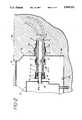
- FIG. 1is an elevational cross-section of an installed underground fuel storage tank provided with a piping system in accordance with the present invention.
- FIG. 2is an elevational cross-section of a portion of the piping system of FIG. 1 showing in greater detail the connection of the flexible pipe with the pump body.
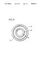
- FIG. 3is a cross-section taken along the line 3--3 of FIG. 2.
- FIG. 4is an elevational cross-section of a portion of the piping system of FIG. 1 showing in greater detail the connection of the flexible pipe with the fuel dispenser.
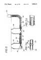
- FIG. 5is a schematic elevational cross-section of the flexible piping run/manifold connection to other underground storage tank systems.
- FIGS. 5A and 5Bare each elevational views in cross-section showing in greater detail certain elements depicted schematically in FIG. 5.
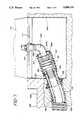
- FIG. 6is an elevational view in partial cross-section of one end of an alternative embodiment of the present invention, showing in detail the connection of the flexible pipe with the pump body, corresponding approximately to FIG. 2.
- FIG. 7is an elevational view in partial cross-section of the other end of the alternative embodiment shown in FIG. 6, showing in detail the connection of the flexible pipe with the dispenser.
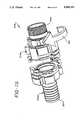
- FIG. 7Ais a perspective view of the quick-disconnect coupling used in the embodiment illustrated in FIGS. 6 and 7, disposed approximately as shown in FIG. 7, but in the disconnected condition.
- FIG. 1shows a conventional underground fuel tank 13 with a single manway 14 having a cover 14a at grade level 28, equipped with a conventional containment chamber 12, which provides access to the pump 37 and the underground piping 19,22 connected to it.
- the underground tank 13is filled with fuel by opening the manway 14 and transferring fuel to tank 13 through the fill pipe 16.
- a pump 37is provided to pump fuel through input pipe 83 from the underground tank 13 through a primary pipe 22 to a fuel dispenser coupling 39 providing input to a fuel dispenser 35.
- the fuel dispenser 35may be a conventional service station gas pump.
- a secondary pipe 19jackets the primary pipe 22 and provides containment for any fuel that might leak out of primary pipe 22.
- the compression fittings 17, 18 for the secondary pipe 19 and the primary pipe 22are now accessible from the containment chamber 12.
- the compression fitting 17 for the secondary pipe 19is disconnected.
- the male-threaded secondary pump coupling 20is next unscrewed from the female-tapped piping adaptor 15, and the secondary pump coupling 20 is forced away from the pump body and adaptor, thereby exposing the compression fitting 18 connecting the primary pipe 22 with the adaptor 23.
- the compression fitting 18can now be disconnected, thus disconnecting the primary pipe 22 and the secondary pipe 19 from the piping adaptor 23 and the pump body 37.
- the other ends of the primary pipe 22 and secondary pipe 19are similarly disconnected from the dispenser coupling 39 at or about grade level 28.
- the inner primary pipe 22can now be “fished” or pulled up and out from the outer secondary pipe 19 from grade level 28.
- the primary pipe 22 and the secondary pipe 19are accessible at both ends--below grade at the interface with the containment chamber 12, and at or about grade level 28 at the fuel dispenser coupling 39. Since the pipes 19, 22 are flexible, the pipe may be shipped to the field site where the tank is installed and cut at the job site to the desired length.
- the piping adaptor 23is a forged or cast custom fitting including two-inch outside diameter inner pipe 23a connected to the outlet port 37a of the pump body 37 below ground.
- the dispenser coupling 39is a corresponding fitting connected to the dispenser inlet port, which conventionally extends from a shear valve.
- the flexible primary pipe 22, desirably of two-inch inner diameterfits over the inner pipe 23a of the piping adaptor 23.
- the compression fitting 18clamps and firmly secures the primary pipe 22 to the piping adaptor 23.
- the length of the inner pipe 23a of the piping adaptor 23is typically two pipe diameters.
- the compression fitting 18may be substituted with a common hose clamp, strap or other fitting. PG,8
- the secondary pump coupling 20is a four-inch outside diameter steel pipe adapter with external male threads. It screws at one threaded end 25 into the outer piping adapter 15.
- the flexible secondary pipe 19is desirably of four-inch inside diameter hose piping. It slides over the free end of the secondary pump coupling 20.
- a compression fitting 17clamps and firmly secures the secondary pipe 19 to the secondary pump coupling 20.
- the secondary pipe 19is rendered inflexible as it is buried in the ground.
- the secondary 19serves as a guide for the primary pipe 22 which slides into or is retractable from it.
- the piping adaptor 23has a male thread 25 that screws into the pump body 37. (In some cases where the pump has a standard male connection, a standard pipe coupling may be necessary to connect the piping adaptor.) Once the piping adaptor 23 is screwed into the port 37a of the pump body 37, the piping adaptor 23 is fixed and is generally not removed.
- a boot 24is used to seal the entry of the secondary pipe 19, where pipe 19 enters the containment chamber 12 by connecting to a sleeve 21 which is an integral part of the containment chamber 12.
- the leakageis contained in the annular space 27 between the primary pipe 22 and secondary pipe 19, and will not escape into and flood the containment chamber 12. If a leak arises at the juncture of the pipe 22 and pump body 37, or at either of the two compression fittings 17 or 18, the presence of boot 24 ensures that the leak is contained in the piping containment chamber 12 and does not overflow into the surrounding soil. The boot 24 also prevents leakage from the fill pipe 16 from escaping from the containment chamber 12 into the soil.
- the annular space 27 between the coaxial primary pipe 22 and secondary pipe 19can be tested for leakage by locating one or more sensors 29 in the annular space 27 between the pipes 22 and 19.
- a manifold connection 67may optionally be provided to link with another storage tank (not shown).
- the linkis created by an inner, primary pipe 82, which is surrounded coaxially by a secondary, containment pipe 79 extending from the manifold connection 67 via a coupling that is equivalent to that between the pump 37 and the pipes 19,22 that extend to the dispenser 35.
- the flexible outer secondary pipe 19is installed below the ground, and then the flexible inner primary pipe 22 is inserted from the grade level 28 into the previously installed secondary pipe 19.
- the belowground ends of the two concentric pipes 19,22are mechanically connected inside the containment chamber 12, which is made accessible by removal of cover 14a.
- the above-ground ends of the two concentric pipes 19,22are mechanically connected inside the containment pan 138 below the fuel dispenser 35.
- coupling 18may be snapped open and the inner pipe 22 may be replaced with a new pipe underground without disturbing the concrete slab at grade level 28. Accordingly, the underground piping is replaceable without going underground.
- FIG. 4schematically illustrates a similar gas dispensing station with an alternate embodiment for securing the primary pipe 122 and secondary pipe 119 to the pump adapter 125 at one end and to the dispenser coupling 139 at the other end in an underground storage tank-dispenser piping system 100.
- fluid 150 leaking from the dispenser 135will drip downwards from at or approximate to grade level 128 into the containment pan 138 where it will pool at the bottom thereof and flow into the annular space 127 between the primary or product pipe 122 and the secondary or containment pipe 119, from which it will drain by gravity to the bottom 126 in the containment chamber 112.
- a leak from the primary pipe 122will similarly flow into the secondary pipe 119 and travel to the bottom 126 of the containment chamber 112.
- the coupling securing the primary pipe 122 to the secondary pipe 119 at the base of the dispenser 135is connected to the bottom of the dispenser coupling 139, which conventionally includes a shear valve.
- This couplingis substantially similar to the coupling at the other end of the double piping system in the containment chamber 112.
- the secondary or containment pipe 119is connected directly to sleeves that protrude from the containment pan 138 at one end and the containment chamber 112 at the other end.
- the method of connectionmay be stainless steel straps or bands 157 applied in the field with a strap tightening and clamping tool. Alternatively, a compression fitting may be used. Access to the containment chamber 112 is provided through the manway 114.
- monitoring systems 129can be installed at the leak collection chamber 26 or 126, and necessary repairs can be performed without an undesired release of fluid to the environment.
- the primary pipe 22 or 122can be replaced from above the ground.
- the material of the primary pipe 22 or 122, and the secondary pipe 19 and 119 in the two aforesaid embodimentsis similar to the conventional "hose" construction, i.e. reinforced rubber or plastic material suitable for gasoline service.
- life expectancy of the underground piping system shown in FIGS. 1, 2, and 4will exceed 10 years instead of the approximately 4 year average life expectancy of conventional above-ground pipe systems.
- a repeater containment chamber 312may be placed in the pipe run.
- the piping containment chamber 212, the primary and secondary piping system 222 and 219, and the fuel dispenser 235are schematically shown in FIG. 5.
- the use of repeater containment chamberswill be necessary in cases where the length of the primary and secondary piping system delivered to the jobsite is less than the distance between the piping containment chamber 312 and the fuel dispenser 235, or if multiple fuel storage tanks are utilized and interconnectors in the piping becomes necessary.
- a pump 337 having an input pipe 383 extending downwardly towards the bottom of storage tank (not shown)is within an underground containment chamber 312.
- a primary pipe 382runs from containment 312 towards a dispenser 235.
- the pipeis not long enough to run all the way to dispenser 235 and instead terminates at an in-line coupling 384.
- the in-line coupling 384communicates with the primary pipe 382 on the one side and with another primary pipe 222 on the other side, joining them to form a continuous passage for fluid.
- Clamps 357secure pipes 382 and 222 to the coupling 384. Any leakage from either of the joints between the in-line coupling and pipe 382 or pipe 222 is contained within containment chamber 212.
- pipe 382should leak and need to be replaced, it can be accomplished without having to replace the entire piping between the pump 337 and the dispenser 235, and correspondingly so for pipe 222.
- FIGS. 6 and 7illustrate an alternative embodiment of the invention which provides particularly advantageous assembly and disassembly.
- the primary pipingis connected to a stationary element such as a pump 537 or dispenser 535 by a banyonet-type quick-disconnect fitting 575 shown in greater detail in FIG. 7A.
- the secondary piping 519is secured thereto by a bellows 590 which retracts to provide access to the quick-disconnect fitting 575 when it is desired to disconnect the primary piping 522, e.g. to replace it.
- a pump 537 having an inlet pipe 583 extending downwardly into an underground storage tank 513is fitted with an adaptor 523.
- the adaptor 523could be molded or welded to the outlet port 540 of the pump 537, or it could be fitted to the port 540 by screw threads.
- the inner portion 523a of the adaptor 523is a straight tube with an outer diameter approximating that of the primary piping 522. Extending from the inner portion is a radial flange 523b, terminating at the juncture with an outer portion 523c coaxial with the inner portion 523a.
- the outer diameter of the outer portion 523cis approximately that of sleeve 580 and of the inner diameter of the secondary piping 519, inasmuch as the secondary piping 519 is clamped around sleeve 580 by compression clamp 559.
- a generally cylindrical bellows 590 having extremities with inner diameters approximating that of the outer portion 523c of adapter 523 and of the sleeve 580is clamped by bellows clamps 557 around each of these elements.
- the sleeve 580extends through an aperture 592 in the containment chamber 512 to which it is hermetically sealed as by welding or sealant 591.
- the quick-disconnect fitting 575consists of two parts, a base part 575a and a nose part 575b.
- the two partsseparate by a relative twisting motion, as illustrated by arrow 601. This is a conventional bayonet action.
- the couplingis sold by Buffalo Tank Corp., Baltimore, Md. and Jacksonville, Fla., as the Advanced Coupling.
- the base part 575bhas a screw threaded base 576 which is secured to the adaptor 523.
- the nose part 575ahas a male extension 577, onto which the end of the primary piping 522 is force fitted and secured by a clamp 558.
- the outer diameter of the nose part 575amay be less than the inner diameter of the sleeve 580, so that it is not necessary to remove the nose part 575a from the end of the primary piping 522 when retrieving it.
- the bellows clamps 557are loosened or removed, and the bellows 590 is compressed, accordion-like, to move it aside and reveal the coupling 575.
- the coupling 575is disconnected, with relative twist 601 of the parts 575a and 575b, permitting the inner piping 522 to be exposed.
- Clamp 558as aforesaid may then be operated if desired to loosen the nose part 575a from the piping 522.
- the adaptor 524may optionally have an L-shaped inner portion 524a rather than the straight inner portion 523a of the adaptor 523 previously described.
- the sleeve 582may extend diagonally as shown, or optionally downwardly, through an aperture in the dispenser pan 584 to which it is sealed as previously described.
- a dispenser 535Conventional elements of a dispenser 535, such as shear valve 510, a mounting angle 511 for the valve 510, a concrete pad 529 on which the dispenser 535 is mounted, and earthen backfill 599, are shown in FIG. 7, wherein grade level is indicated at 528.
- the secondary piping systemis most desirably open to the environment at its ends, so that fluid collecting in a dispenser pan can drain into the annular volume between the primary piping and secondary piping, and/or drain out therefrom into a containment. See FIG. 4.
- FIGS. 6 and 7Alternatively there are embodiments wherein the ends of the piping are desirably sealed by the adaptors, e.g. FIGS. 6 and 7.
- Such adaptorscan, however, have openings built therein to modify them for use in the system shown in FIG. 4, if the opposite is desired under conditions of use.
Landscapes
- Engineering & Computer Science (AREA)
- General Engineering & Computer Science (AREA)
- Mechanical Engineering (AREA)
- Loading And Unloading Of Fuel Tanks Or Ships (AREA)
- Rigid Pipes And Flexible Pipes (AREA)
- Pipeline Systems (AREA)
- Quick-Acting Or Multi-Walled Pipe Joints (AREA)
- Filling Or Discharging Of Gas Storage Vessels (AREA)
Abstract
Description
Claims (17)
Priority Applications (8)
| Application Number | Priority Date | Filing Date | Title |
|---|---|---|---|
| US07/411,385US5098221A (en) | 1988-12-20 | 1989-09-22 | Flexible double-containment piping system for underground storage tanks |
| ES90902082TES2158837T3 (en) | 1988-12-20 | 1989-12-20 | FLEXIBLE SYSTEM OF DOUBLE CONTAINER PIPES. |
| DE68929300TDE68929300T2 (en) | 1988-12-20 | 1989-12-20 | FLEXIBLE, DOUBLE SECURED TUBE SYSTEM |
| JP50243090AJP2933094B2 (en) | 1988-12-20 | 1989-12-20 | Flexible double containment piping system for underground storage tanks. |
| AU49499/90AAU651312B2 (en) | 1988-12-20 | 1989-12-20 | Flexible double containment piping system |
| EP90902082AEP0464027B1 (en) | 1988-12-20 | 1989-12-20 | Flexible double-containment piping system |
| AT90902082TATE201757T1 (en) | 1988-12-20 | 1989-12-20 | FLEXIBLE, DOUBLE SECURED PIPE SYSTEM |
| PCT/US1989/005845WO1990007674A1 (en) | 1988-12-20 | 1989-12-20 | Flexible double-containment piping system |
Applications Claiming Priority (2)
| Application Number | Priority Date | Filing Date | Title |
|---|---|---|---|
| US07/286,893US5553971A (en) | 1988-12-20 | 1988-12-20 | Double-containment underground piping system |
| US07/411,385US5098221A (en) | 1988-12-20 | 1989-09-22 | Flexible double-containment piping system for underground storage tanks |
Related Parent Applications (1)
| Application Number | Title | Priority Date | Filing Date |
|---|---|---|---|
| US07/286,893Continuation-In-PartUS5553971A (en) | 1988-12-20 | 1988-12-20 | Double-containment underground piping system |
Publications (1)
| Publication Number | Publication Date |
|---|---|
| US5098221Atrue US5098221A (en) | 1992-03-24 |
Family
ID=26964124
Family Applications (1)
| Application Number | Title | Priority Date | Filing Date |
|---|---|---|---|
| US07/411,385Expired - LifetimeUS5098221A (en) | 1988-12-20 | 1989-09-22 | Flexible double-containment piping system for underground storage tanks |
Country Status (7)
| Country | Link |
|---|---|
| US (1) | US5098221A (en) |
| EP (1) | EP0464027B1 (en) |
| AT (1) | ATE201757T1 (en) |
| AU (1) | AU651312B2 (en) |
| DE (1) | DE68929300T2 (en) |
| ES (1) | ES2158837T3 (en) |
| WO (1) | WO1990007674A1 (en) |
Cited By (58)
| Publication number | Priority date | Publication date | Assignee | Title |
|---|---|---|---|---|
| US5252000A (en)* | 1992-06-24 | 1993-10-12 | Timothy E. Mohs | Free product collector and method |
| US5263794A (en)* | 1992-02-19 | 1993-11-23 | Environ Products, Inc. | Environmentally safe underground piping system |
| US5297896A (en)* | 1992-02-19 | 1994-03-29 | Environ Products, Inc. | Environmentally safe underground piping system |
| US5343738A (en)* | 1992-10-16 | 1994-09-06 | Furon Company | Double walled containment fuel transfer hose |
| US5427474A (en)* | 1993-01-25 | 1995-06-27 | Ameron, Inc. | Double containment piping system and centralization seal therefor |
| US5429274A (en)* | 1993-02-17 | 1995-07-04 | Vlaskamp; Peter L. | Petroleum collector system |
| US5527130A (en)* | 1992-02-19 | 1996-06-18 | Environ Products, Inc. | Environmentally safe underground piping system |
| US5577862A (en)* | 1995-01-31 | 1996-11-26 | C.M.F. Corporation | Underground containment for fluid systems |
| US5722699A (en)* | 1990-07-18 | 1998-03-03 | Environ Products, Inc. | Flexible entry seal arrangement |
| US5760294A (en)* | 1990-06-02 | 1998-06-02 | Lehmann; Martin | Method of and apparatus for checking the volume of containers |
| US5775842A (en)* | 1988-12-20 | 1998-07-07 | Pisces By Opw, Inc. | Double containment under ground piping system |
| US5819975A (en)* | 1996-10-08 | 1998-10-13 | Dover Corp. | Dispenser sump |
| US5833391A (en)* | 1997-05-13 | 1998-11-10 | Daigle; Todd | Chemical pump containment and method of containing liquid spillage |
| US5865216A (en) | 1995-11-08 | 1999-02-02 | Advanced Polymer Technology, Inc. | System for housing secondarily contained flexible piping |
| US5870952A (en)* | 1995-03-03 | 1999-02-16 | Man Roland Druckmaschinen Ag | Damping unit box for a damping unit of an offset printing machine |
| US5911155A (en)* | 1992-08-03 | 1999-06-08 | Environ Products, Inc. | Connecting device for pipe assemblies |
| US5950860A (en)* | 1996-10-08 | 1999-09-14 | Dover Corp. | Adjustable length storage tank sumps |
| US5961155A (en) | 1996-07-11 | 1999-10-05 | Advanced Polymer Technology, Inc. | Flexible entry boot |
| US5967567A (en) | 1998-01-15 | 1999-10-19 | Advanced Polymer Technology, Inc. | Matingly engaged flexible entry boot |
| US5975110A (en)* | 1997-09-18 | 1999-11-02 | Sharp; Bruce R. | Adapter assembly for accessing primary pipeline of a double wall pipeline system |
| US6086117A (en) | 1998-05-05 | 2000-07-11 | Advanced Polymer Technology, Inc. | Double booted flexible entry boot |
| USD429735S (en)* | 1998-07-23 | 2000-08-22 | Advanced Polymer Technology, Inc. | Integrally formed tank sump with lid |
| US6123365A (en)* | 1996-10-08 | 2000-09-26 | Delaware Capital Formation, Inc. | Structure for protecting a bulkhead fitting |
| US6173997B1 (en) | 1996-07-11 | 2001-01-16 | Advanced Polymer Technology, Inc. | Flexible entry boot |
| US6182679B1 (en)* | 1998-10-06 | 2001-02-06 | Delaware Capital Formation, Inc. | Sump stabilizer bar |
| US6189717B1 (en) | 1998-09-14 | 2001-02-20 | Advanced Polymer Technology, Inc. | Integrally formed tank sump with water resistant lid assembly |
| USRE37114E1 (en) | 1993-11-01 | 2001-03-27 | Advanced Polymer Technology, Inc. | Secondary containment flexible underground piping system |
| US6209569B1 (en) | 1997-09-18 | 2001-04-03 | Bruce R. Sharp | Safety shut-off valve assembly for a fuel dispenser |
| US6371154B1 (en) | 1999-09-17 | 2002-04-16 | Fisces By Opw, Inc. | Apparatus and system for containment |
| US20020084402A1 (en)* | 2000-11-03 | 2002-07-04 | Schauer Ronald Vern | Facilities connection bucket for pre-facilitation of wafer fabrication equipment |
| US20030230593A1 (en)* | 2002-06-18 | 2003-12-18 | Hutchinson Ray J. | Service station leak detection and recovery system |
| US20040020271A1 (en)* | 2002-07-31 | 2004-02-05 | Hutchinson Ray J. | Contaminant containment system in a fueling environment |
| US20040045343A1 (en)* | 2002-09-10 | 2004-03-11 | Hutchinson Ray J. | Secondary containment system and method |
| US6729797B2 (en) | 2001-08-15 | 2004-05-04 | Delaware Capital Formation, Inc. | Testable sump apparatus |
| US20040149017A1 (en)* | 2002-09-10 | 2004-08-05 | Hutchinson Ray J. | Secondary containment leak prevention and detection system and method |
| US20040182136A1 (en)* | 2003-03-17 | 2004-09-23 | Don Halla | Fuel storage tank leak prevention and detection system and method |
| US20040261504A1 (en)* | 2002-09-10 | 2004-12-30 | Hutchinson Ray J | Secondary containment leak prevention and detection system and method in fuel dispenser |
| US20040261503A1 (en)* | 2002-09-10 | 2004-12-30 | Hutchinson Ray J. | Power head secondary containment leak prevention and detection system and method |
| US20050169710A1 (en)* | 2003-12-11 | 2005-08-04 | Folkers Joie L. | Containment system |
| EP1595844A1 (en)* | 2004-05-15 | 2005-11-16 | Delaware Capital Formation, Inc. | Dipenser sump with passageway for wires |
| US7032614B2 (en) | 2000-11-03 | 2006-04-25 | Applied Materials, Inc. | Facilities connection box for pre-facilitation of wafer fabrication equipment |
| US7069956B1 (en) | 2003-10-23 | 2006-07-04 | Mosier James W | Marina piping |
| US20060191568A1 (en)* | 2005-02-18 | 2006-08-31 | Veeder-Root Company | Double-walled contained shear valve, particularly for fueling environments |
| US20060191569A1 (en)* | 2005-02-18 | 2006-08-31 | Veeder-Root Company | Double-walled contained shear valve, particularly for fueling environments |
| US20060249204A1 (en)* | 2005-02-18 | 2006-11-09 | Veeder-Root Company | Shear valve employing two-stage poppet valve, particularly for use in fueling environments |
| US20060260680A1 (en)* | 2005-04-26 | 2006-11-23 | Veeder-Root Company | Vacuum-actuated shear valve device, system, and method, particularly for use in service station environments |
| US7171994B1 (en) | 2005-09-28 | 2007-02-06 | O'brien Patrick E | Spillage containment system and kit for underground storage tanks |
| WO2007024795A1 (en) | 2005-08-22 | 2007-03-01 | Parker-Hannifin Corporation | Secondarily contained annularly corrugated steel tube pipe and fitting |
| US20070053747A1 (en)* | 2005-08-23 | 2007-03-08 | O'brien Patrick E | Underground storage tank access/isolation riser assembly, method, and kit |
| US7195284B2 (en) | 2004-07-19 | 2007-03-27 | Snyder Industries, Inc. | Flexible synthetic resin coupling |
| US20070144606A1 (en)* | 2005-09-28 | 2007-06-28 | O'brien Patrick E | Manhole skirt assembly and kit |
| US20080055377A1 (en)* | 2006-08-29 | 2008-03-06 | Xerox Corporation | System and method for transporting fluid through a conduit |
| US20090223595A1 (en)* | 2008-03-04 | 2009-09-10 | Delaware Capital Formation, Inc. | Spill containment apparatus for storage tanks |
| US20100276018A1 (en)* | 2006-12-20 | 2010-11-04 | Xerox Corporation | System For Maintaining Temperature Of A Fluid In A Conduit |
| US20110205317A1 (en)* | 2006-12-22 | 2011-08-25 | Xerox Corporation | Heated Ink Delivery System |
| US8308278B2 (en) | 2010-04-02 | 2012-11-13 | Xerox Corporation | System and method for operating a conduit to transport fluid through the conduit |
| US20130327497A1 (en)* | 2010-11-08 | 2013-12-12 | Geoenergy Enterprises, Llc | Method of heating/cooling structure using geothermal system |
| CN109847446A (en)* | 2019-03-29 | 2019-06-07 | 德州翔宇黄河水利工程维修养护有限责任公司 | A kind of piping water sand separation filters pressing well |
Families Citing this family (6)
| Publication number | Priority date | Publication date | Assignee | Title |
|---|---|---|---|---|
| US4971477A (en)* | 1988-12-22 | 1990-11-20 | Total Containment, Inc. | Secondary contained fluid supply system |
| US5556679A (en)* | 1994-04-15 | 1996-09-17 | A. O. Smith Corporation | Flexible dual wall hose or pipe assembly |
| FR2735085B1 (en)* | 1995-06-12 | 1997-09-05 | Total Raffinage Distribution | PIPING SYSTEM FOR FILLING LIQUID FUEL FROM AN UNDERGROUND TANK AND FOR TRANSFERRING THIS FUEL TO A DISTRIBUTION STATION |
| CN104019374A (en)* | 2014-06-25 | 2014-09-03 | 济钢集团有限公司 | Leak-proof device for gas pipeline regulating valve |
| EP4311052A1 (en)* | 2022-07-17 | 2024-01-24 | Symalit AG | Cable protection pipe system, in particular for a hanging position, and use |
| EP4322349A1 (en)* | 2022-08-08 | 2024-02-14 | Symalit AG | Cable protection tube system, in particular for a slope, and use |
Citations (26)
| Publication number | Priority date | Publication date | Assignee | Title |
|---|---|---|---|---|
| US1188446A (en)* | 1915-04-22 | 1916-06-27 | Johnathan Haines | Gasolene-supply apparatus. |
| US2268263A (en)* | 1941-05-15 | 1941-12-30 | Dresser Mfg Company | Pipe fitting |
| US2336150A (en)* | 1940-06-24 | 1943-12-07 | Dayton Pump & Mfg Co | Airport gasoline dispensing system |
| US2546348A (en)* | 1947-08-19 | 1951-03-27 | Dresser Ind | Service head fitting |
| US2956586A (en)* | 1959-09-03 | 1960-10-18 | Gen Motors Corp | Hose arrangement |
| US3559408A (en)* | 1968-09-26 | 1971-02-02 | Mar M Earnhart | Spring development system |
| US3721270A (en)* | 1969-09-02 | 1973-03-20 | G Wittgenstein | Safety installation for preventing pollution by pipelines |
| US4009739A (en)* | 1975-09-02 | 1977-03-01 | Weatherford Danny J | Gasoline and vapor return hose system for delivery truck |
| US4062376A (en)* | 1975-09-05 | 1977-12-13 | Mcgrath Robert L | Service connection between a main and a meter in a building and method of and equipment for installing the same |
| US4094536A (en)* | 1976-12-20 | 1978-06-13 | Continental Industries, Inc. | Meter riser |
| US4110947A (en)* | 1977-12-09 | 1978-09-05 | Murgor Electric Company, Inc. | Storage tank installation |
| US4127286A (en)* | 1977-10-11 | 1978-11-28 | Corning Glass Works | Concentric pipe coupling |
| US4149568A (en)* | 1977-12-07 | 1979-04-17 | Caterpillar Tractor Co. | Double walled fuel line |
| US4449853A (en)* | 1983-04-11 | 1984-05-22 | Mennella Robert J | Flexible sleeve elbow for gas service lines |
| US4519634A (en)* | 1982-12-22 | 1985-05-28 | Hand James D | Transition pipe fitting |
| US4639164A (en)* | 1985-05-06 | 1987-01-27 | Owens-Corning Fiberglas Corporation | Underground tank sump and piping system |
| US4644780A (en)* | 1983-10-19 | 1987-02-24 | Westinghouse Electric Corp. | Self-supporting pipe rupture and whip restraint |
| US4682911A (en)* | 1984-03-06 | 1987-07-28 | Mpc Containment Systems, Ltd. | Secondary containment systems especially well suited for hydrocarbon storage and delivery systems |
| US4739648A (en)* | 1985-12-09 | 1988-04-26 | Horner John A | Methods and system for determining leaks in underground liquid storage tanks and the like |
| US4787772A (en)* | 1987-06-26 | 1988-11-29 | Eljen Corporation | Device for detecting leaks in underground fluid tanks |
| US4796676A (en)* | 1987-06-05 | 1989-01-10 | Hendershot John A | Fluid storage tank system |
| US4805444A (en)* | 1987-10-01 | 1989-02-21 | Webb Michael C | Secondary containment system |
| US4912966A (en)* | 1985-06-17 | 1990-04-03 | Sharp Bruce R | Total containment means for storage tank systems |
| WO1990004157A1 (en)* | 1988-10-06 | 1990-04-19 | Total Containment | Secondary containment system using flexible piping |
| US4932257A (en)* | 1987-10-01 | 1990-06-12 | Webb Michael C | Double wall piping system |
| US4971477A (en)* | 1988-12-22 | 1990-11-20 | Total Containment, Inc. | Secondary contained fluid supply system |
Family Cites Families (8)
| Publication number | Priority date | Publication date | Assignee | Title |
|---|---|---|---|---|
| US648128A (en)* | 1899-06-14 | 1900-04-24 | David Young Kinniburgh | System for laying supply-pipes. |
| DE638911C (en)* | 1934-05-24 | 1936-11-25 | Heinrich Roehm | Revolving core tip |
| US3841671A (en)* | 1973-10-30 | 1974-10-15 | Gen Motors Corp | Coaxial fluid lines with plug-in connector assemblies |
| US4561292A (en)* | 1984-01-19 | 1985-12-31 | Owens-Corning Fiberglas Corporation | Double-wall underground container for storing liquids and leak detecting means therefor |
| US4919305A (en)* | 1987-11-06 | 1990-04-24 | Emco Wheaton, Inc. | Fuel dispensing nozzle with built-in flow regulator |
| US5065616A (en)* | 1989-05-01 | 1991-11-19 | Peter Schuster | Hydrostatic line testing and method |
| US5213142A (en)* | 1991-03-04 | 1993-05-25 | Amoco Corporation | Stage II vapor recovery system |
| US5868175A (en)* | 1996-06-28 | 1999-02-09 | Franklin Electric Co., Inc. | Apparatus for recovery of fuel vapor |
- 1989
- 1989-09-22USUS07/411,385patent/US5098221A/ennot_activeExpired - Lifetime
- 1989-12-20AUAU49499/90Apatent/AU651312B2/ennot_activeExpired
- 1989-12-20ESES90902082Tpatent/ES2158837T3/ennot_activeExpired - Lifetime
- 1989-12-20WOPCT/US1989/005845patent/WO1990007674A1/enactiveIP Right Grant
- 1989-12-20DEDE68929300Tpatent/DE68929300T2/ennot_activeExpired - Lifetime
- 1989-12-20EPEP90902082Apatent/EP0464027B1/ennot_activeExpired - Lifetime
- 1989-12-20ATAT90902082Tpatent/ATE201757T1/ennot_activeIP Right Cessation
Patent Citations (26)
| Publication number | Priority date | Publication date | Assignee | Title |
|---|---|---|---|---|
| US1188446A (en)* | 1915-04-22 | 1916-06-27 | Johnathan Haines | Gasolene-supply apparatus. |
| US2336150A (en)* | 1940-06-24 | 1943-12-07 | Dayton Pump & Mfg Co | Airport gasoline dispensing system |
| US2268263A (en)* | 1941-05-15 | 1941-12-30 | Dresser Mfg Company | Pipe fitting |
| US2546348A (en)* | 1947-08-19 | 1951-03-27 | Dresser Ind | Service head fitting |
| US2956586A (en)* | 1959-09-03 | 1960-10-18 | Gen Motors Corp | Hose arrangement |
| US3559408A (en)* | 1968-09-26 | 1971-02-02 | Mar M Earnhart | Spring development system |
| US3721270A (en)* | 1969-09-02 | 1973-03-20 | G Wittgenstein | Safety installation for preventing pollution by pipelines |
| US4009739A (en)* | 1975-09-02 | 1977-03-01 | Weatherford Danny J | Gasoline and vapor return hose system for delivery truck |
| US4062376A (en)* | 1975-09-05 | 1977-12-13 | Mcgrath Robert L | Service connection between a main and a meter in a building and method of and equipment for installing the same |
| US4094536A (en)* | 1976-12-20 | 1978-06-13 | Continental Industries, Inc. | Meter riser |
| US4127286A (en)* | 1977-10-11 | 1978-11-28 | Corning Glass Works | Concentric pipe coupling |
| US4149568A (en)* | 1977-12-07 | 1979-04-17 | Caterpillar Tractor Co. | Double walled fuel line |
| US4110947A (en)* | 1977-12-09 | 1978-09-05 | Murgor Electric Company, Inc. | Storage tank installation |
| US4519634A (en)* | 1982-12-22 | 1985-05-28 | Hand James D | Transition pipe fitting |
| US4449853A (en)* | 1983-04-11 | 1984-05-22 | Mennella Robert J | Flexible sleeve elbow for gas service lines |
| US4644780A (en)* | 1983-10-19 | 1987-02-24 | Westinghouse Electric Corp. | Self-supporting pipe rupture and whip restraint |
| US4682911A (en)* | 1984-03-06 | 1987-07-28 | Mpc Containment Systems, Ltd. | Secondary containment systems especially well suited for hydrocarbon storage and delivery systems |
| US4639164A (en)* | 1985-05-06 | 1987-01-27 | Owens-Corning Fiberglas Corporation | Underground tank sump and piping system |
| US4912966A (en)* | 1985-06-17 | 1990-04-03 | Sharp Bruce R | Total containment means for storage tank systems |
| US4739648A (en)* | 1985-12-09 | 1988-04-26 | Horner John A | Methods and system for determining leaks in underground liquid storage tanks and the like |
| US4796676A (en)* | 1987-06-05 | 1989-01-10 | Hendershot John A | Fluid storage tank system |
| US4787772A (en)* | 1987-06-26 | 1988-11-29 | Eljen Corporation | Device for detecting leaks in underground fluid tanks |
| US4805444A (en)* | 1987-10-01 | 1989-02-21 | Webb Michael C | Secondary containment system |
| US4932257A (en)* | 1987-10-01 | 1990-06-12 | Webb Michael C | Double wall piping system |
| WO1990004157A1 (en)* | 1988-10-06 | 1990-04-19 | Total Containment | Secondary containment system using flexible piping |
| US4971477A (en)* | 1988-12-22 | 1990-11-20 | Total Containment, Inc. | Secondary contained fluid supply system |
Cited By (101)
| Publication number | Priority date | Publication date | Assignee | Title |
|---|---|---|---|---|
| US6116817A (en)* | 1988-12-20 | 2000-09-12 | Pisces By Opw, Inc. | Hydrocarbon fuel piping system with a flexible inner pipe and an outer pipe |
| US5775842A (en)* | 1988-12-20 | 1998-07-07 | Pisces By Opw, Inc. | Double containment under ground piping system |
| US5760294A (en)* | 1990-06-02 | 1998-06-02 | Lehmann; Martin | Method of and apparatus for checking the volume of containers |
| US5722699A (en)* | 1990-07-18 | 1998-03-03 | Environ Products, Inc. | Flexible entry seal arrangement |
| US5527130A (en)* | 1992-02-19 | 1996-06-18 | Environ Products, Inc. | Environmentally safe underground piping system |
| US5297896A (en)* | 1992-02-19 | 1994-03-29 | Environ Products, Inc. | Environmentally safe underground piping system |
| US5263794A (en)* | 1992-02-19 | 1993-11-23 | Environ Products, Inc. | Environmentally safe underground piping system |
| US5252000A (en)* | 1992-06-24 | 1993-10-12 | Timothy E. Mohs | Free product collector and method |
| US5911155A (en)* | 1992-08-03 | 1999-06-08 | Environ Products, Inc. | Connecting device for pipe assemblies |
| US6029505A (en)* | 1992-08-03 | 2000-02-29 | Environ Products, Inc. | Connecting device for pipe assemblies |
| US5343738A (en)* | 1992-10-16 | 1994-09-06 | Furon Company | Double walled containment fuel transfer hose |
| US5427474A (en)* | 1993-01-25 | 1995-06-27 | Ameron, Inc. | Double containment piping system and centralization seal therefor |
| US5429274A (en)* | 1993-02-17 | 1995-07-04 | Vlaskamp; Peter L. | Petroleum collector system |
| USRE37114E1 (en) | 1993-11-01 | 2001-03-27 | Advanced Polymer Technology, Inc. | Secondary containment flexible underground piping system |
| US5577862A (en)* | 1995-01-31 | 1996-11-26 | C.M.F. Corporation | Underground containment for fluid systems |
| US5870952A (en)* | 1995-03-03 | 1999-02-16 | Man Roland Druckmaschinen Ag | Damping unit box for a damping unit of an offset printing machine |
| US5865216A (en) | 1995-11-08 | 1999-02-02 | Advanced Polymer Technology, Inc. | System for housing secondarily contained flexible piping |
| US5961155A (en) | 1996-07-11 | 1999-10-05 | Advanced Polymer Technology, Inc. | Flexible entry boot |
| US6612620B1 (en) | 1996-07-11 | 2003-09-02 | Advanced Polymer Technology, Inc. | Flexible entry boot |
| US6173997B1 (en) | 1996-07-11 | 2001-01-16 | Advanced Polymer Technology, Inc. | Flexible entry boot |
| US5950860A (en)* | 1996-10-08 | 1999-09-14 | Dover Corp. | Adjustable length storage tank sumps |
| US6224115B1 (en) | 1996-10-08 | 2001-05-01 | Delaware Capital Formation, Inc. | Bulkhead fitting for underground sump |
| US5819975A (en)* | 1996-10-08 | 1998-10-13 | Dover Corp. | Dispenser sump |
| US6123365A (en)* | 1996-10-08 | 2000-09-26 | Delaware Capital Formation, Inc. | Structure for protecting a bulkhead fitting |
| US5833391A (en)* | 1997-05-13 | 1998-11-10 | Daigle; Todd | Chemical pump containment and method of containing liquid spillage |
| US5975110A (en)* | 1997-09-18 | 1999-11-02 | Sharp; Bruce R. | Adapter assembly for accessing primary pipeline of a double wall pipeline system |
| US6209569B1 (en) | 1997-09-18 | 2001-04-03 | Bruce R. Sharp | Safety shut-off valve assembly for a fuel dispenser |
| US6145891A (en) | 1997-09-29 | 2000-11-14 | Advanced Polymer Technology, Inc. | Double booted flexible entry boot |
| US5967567A (en) | 1998-01-15 | 1999-10-19 | Advanced Polymer Technology, Inc. | Matingly engaged flexible entry boot |
| US6086117A (en) | 1998-05-05 | 2000-07-11 | Advanced Polymer Technology, Inc. | Double booted flexible entry boot |
| USD429735S (en)* | 1998-07-23 | 2000-08-22 | Advanced Polymer Technology, Inc. | Integrally formed tank sump with lid |
| US6189717B1 (en) | 1998-09-14 | 2001-02-20 | Advanced Polymer Technology, Inc. | Integrally formed tank sump with water resistant lid assembly |
| US6182679B1 (en)* | 1998-10-06 | 2001-02-06 | Delaware Capital Formation, Inc. | Sump stabilizer bar |
| US6371154B1 (en) | 1999-09-17 | 2002-04-16 | Fisces By Opw, Inc. | Apparatus and system for containment |
| US20020084402A1 (en)* | 2000-11-03 | 2002-07-04 | Schauer Ronald Vern | Facilities connection bucket for pre-facilitation of wafer fabrication equipment |
| US7063301B2 (en) | 2000-11-03 | 2006-06-20 | Applied Materials, Inc. | Facilities connection bucket for pre-facilitation of wafer fabrication equipment |
| US7032614B2 (en) | 2000-11-03 | 2006-04-25 | Applied Materials, Inc. | Facilities connection box for pre-facilitation of wafer fabrication equipment |
| US6729797B2 (en) | 2001-08-15 | 2004-05-04 | Delaware Capital Formation, Inc. | Testable sump apparatus |
| US20050205157A1 (en)* | 2002-06-18 | 2005-09-22 | Gilbarco Inc. | Service station leak detection and recovery system |
| US6935161B2 (en) | 2002-06-18 | 2005-08-30 | Gilbarco Inc. | Service station leak detection and recovery system |
| US7455194B2 (en) | 2002-06-18 | 2008-11-25 | Gilbarco Inc. | Service station leak detection and recovery system |
| US20030230593A1 (en)* | 2002-06-18 | 2003-12-18 | Hutchinson Ray J. | Service station leak detection and recovery system |
| US20030230592A1 (en)* | 2002-06-18 | 2003-12-18 | Hutchinson Ray J. | Service station leak detection and recovery system |
| US6974054B2 (en)* | 2002-06-18 | 2005-12-13 | Gilbarco Inc. | Service station leak detection with recovery system |
| US6962269B2 (en) | 2002-06-18 | 2005-11-08 | Gilbarco Inc. | Service station leak detection and recovery system |
| US20050034508A1 (en)* | 2002-06-18 | 2005-02-17 | Hutchinson Ray J. | Service station leak detection and recovery system |
| US20040020271A1 (en)* | 2002-07-31 | 2004-02-05 | Hutchinson Ray J. | Contaminant containment system in a fueling environment |
| US7051576B2 (en) | 2002-09-10 | 2006-05-30 | Gilbarco Inc. | Secondary containment leak prevention and detection system and method |
| US7010961B2 (en) | 2002-09-10 | 2006-03-14 | Gilbarco Inc. | Power head secondary containment leak prevention and detection system and method |
| US7225664B2 (en) | 2002-09-10 | 2007-06-05 | Gilbarco Inc. | Secondary containment leak prevention and detection system and method |
| US20050145016A1 (en)* | 2002-09-10 | 2005-07-07 | Gilbarco Inc. | Secondary containment leak prevention and detection system and method |
| US20050039518A1 (en)* | 2002-09-10 | 2005-02-24 | Hutchinson Ray J. | Secondary containment leak prevention and detection system and method |
| US20040261503A1 (en)* | 2002-09-10 | 2004-12-30 | Hutchinson Ray J. | Power head secondary containment leak prevention and detection system and method |
| US20050247111A1 (en)* | 2002-09-10 | 2005-11-10 | Gilbarco Inc. | Secondary containment leak prevention and detection system and method |
| US20050247112A1 (en)* | 2002-09-10 | 2005-11-10 | Gilbarco Inc. | Power head secondary containment leak prevention and detection system and method |
| US7251983B2 (en)* | 2002-09-10 | 2007-08-07 | Gilbarco Inc. | Secondary containment system and method |
| US20040045343A1 (en)* | 2002-09-10 | 2004-03-11 | Hutchinson Ray J. | Secondary containment system and method |
| US20040261504A1 (en)* | 2002-09-10 | 2004-12-30 | Hutchinson Ray J | Secondary containment leak prevention and detection system and method in fuel dispenser |
| US6978660B2 (en) | 2002-09-10 | 2005-12-27 | Gilbarco Inc. | Power head secondary containment leak prevention and detection system and method |
| US6997042B2 (en) | 2002-09-10 | 2006-02-14 | Gilbarco Inc. | Secondary containment leak prevention and detection system and method |
| US20050145015A1 (en)* | 2002-09-10 | 2005-07-07 | Gilbarco Inc. | Secondary containment leak prevention and detection system and method |
| US20040149017A1 (en)* | 2002-09-10 | 2004-08-05 | Hutchinson Ray J. | Secondary containment leak prevention and detection system and method |
| US20060090547A1 (en)* | 2002-09-10 | 2006-05-04 | Gilbarco Inc. | Power head secondary containment leak prevention and detection system and method |
| US7080546B2 (en) | 2002-09-10 | 2006-07-25 | Gilbarco Inc. | Secondary containment leak prevention and detection system and method |
| US7076994B2 (en) | 2002-09-10 | 2006-07-18 | Gilbarco Inc. | Power head secondary containment leak prevention and detection system and method |
| US20040182136A1 (en)* | 2003-03-17 | 2004-09-23 | Don Halla | Fuel storage tank leak prevention and detection system and method |
| US6834534B2 (en) | 2003-03-17 | 2004-12-28 | Veeder-Root Company | Fuel storage tank leak prevention and detection system and method |
| US7069956B1 (en) | 2003-10-23 | 2006-07-04 | Mosier James W | Marina piping |
| US20050169710A1 (en)* | 2003-12-11 | 2005-08-04 | Folkers Joie L. | Containment system |
| US20050252932A1 (en)* | 2004-05-15 | 2005-11-17 | Mccann Michael T | Dispenser sump |
| US7401621B2 (en) | 2004-05-15 | 2008-07-22 | Pisces By Opw, Inc. | Dispenser sump |
| EP1595844A1 (en)* | 2004-05-15 | 2005-11-16 | Delaware Capital Formation, Inc. | Dipenser sump with passageway for wires |
| US7195284B2 (en) | 2004-07-19 | 2007-03-27 | Snyder Industries, Inc. | Flexible synthetic resin coupling |
| US20060191569A1 (en)* | 2005-02-18 | 2006-08-31 | Veeder-Root Company | Double-walled contained shear valve, particularly for fueling environments |
| US7681583B2 (en) | 2005-02-18 | 2010-03-23 | Veeder-Root Company | Double-walled contained shear valve, particularly for fueling environments |
| US8387646B2 (en) | 2005-02-18 | 2013-03-05 | Veeder-Root Company | Double-walled contained shear valve, particularly for fueling environments |
| US8096315B2 (en) | 2005-02-18 | 2012-01-17 | Veeder-Root Company | Double-walled contained shear valve, particularly for fueling environments |
| US20060249204A1 (en)* | 2005-02-18 | 2006-11-09 | Veeder-Root Company | Shear valve employing two-stage poppet valve, particularly for use in fueling environments |
| US20060191568A1 (en)* | 2005-02-18 | 2006-08-31 | Veeder-Root Company | Double-walled contained shear valve, particularly for fueling environments |
| US7753067B2 (en) | 2005-02-18 | 2010-07-13 | Veeder-Root Company | Shear valve employing two-stage poppet valve, particularly for use in fueling environments |
| US8291928B2 (en) | 2005-04-26 | 2012-10-23 | Veeder-Root Company | Vacuum-actuated shear valve device, system, and method, particularly for use in service station environments |
| US20060260680A1 (en)* | 2005-04-26 | 2006-11-23 | Veeder-Root Company | Vacuum-actuated shear valve device, system, and method, particularly for use in service station environments |
| US7946309B2 (en) | 2005-04-26 | 2011-05-24 | Veeder-Root Company | Vacuum-actuated shear valve device, system, and method, particularly for use in service station environments |
| WO2007024795A1 (en) | 2005-08-22 | 2007-03-01 | Parker-Hannifin Corporation | Secondarily contained annularly corrugated steel tube pipe and fitting |
| US7390142B2 (en) | 2005-08-23 | 2008-06-24 | O'brien Patrick E | Underground storage tank access/isolation riser assembly, method, and kit |
| US20070053747A1 (en)* | 2005-08-23 | 2007-03-08 | O'brien Patrick E | Underground storage tank access/isolation riser assembly, method, and kit |
| US20070144606A1 (en)* | 2005-09-28 | 2007-06-28 | O'brien Patrick E | Manhole skirt assembly and kit |
| US7171994B1 (en) | 2005-09-28 | 2007-02-06 | O'brien Patrick E | Spillage containment system and kit for underground storage tanks |
| EP1894732A3 (en)* | 2006-08-29 | 2009-05-06 | Xerox Corporation | System and method for transporting fluid through a conduit |
| US20080055377A1 (en)* | 2006-08-29 | 2008-03-06 | Xerox Corporation | System and method for transporting fluid through a conduit |
| US8186817B2 (en) | 2006-08-29 | 2012-05-29 | Xerox Corporation | System and method for transporting fluid through a conduit |
| US20100276018A1 (en)* | 2006-12-20 | 2010-11-04 | Xerox Corporation | System For Maintaining Temperature Of A Fluid In A Conduit |
| US8186818B2 (en) | 2006-12-20 | 2012-05-29 | Xerox Corporation | System for maintaining temperature of a fluid in a conduit |
| US20110205317A1 (en)* | 2006-12-22 | 2011-08-25 | Xerox Corporation | Heated Ink Delivery System |
| US8308281B2 (en) | 2006-12-22 | 2012-11-13 | Xerox Corporation | Heated ink delivery system |
| US20090223595A1 (en)* | 2008-03-04 | 2009-09-10 | Delaware Capital Formation, Inc. | Spill containment apparatus for storage tanks |
| US8622097B2 (en) | 2008-03-04 | 2014-01-07 | Delaware Capital Formation, Inc. | Spill containment apparatus for storage tanks |
| US8308278B2 (en) | 2010-04-02 | 2012-11-13 | Xerox Corporation | System and method for operating a conduit to transport fluid through the conduit |
| US8585195B2 (en) | 2010-04-02 | 2013-11-19 | Xerox Corporation | System and method for operating a conduit to transport fluid through the conduit |
| US20130327497A1 (en)* | 2010-11-08 | 2013-12-12 | Geoenergy Enterprises, Llc | Method of heating/cooling structure using geothermal system |
| CN109847446A (en)* | 2019-03-29 | 2019-06-07 | 德州翔宇黄河水利工程维修养护有限责任公司 | A kind of piping water sand separation filters pressing well |
Also Published As
| Publication number | Publication date |
|---|---|
| DE68929300T2 (en) | 2001-12-06 |
| WO1990007674A1 (en) | 1990-07-12 |
| ES2158837T3 (en) | 2001-09-16 |
| EP0464027B1 (en) | 2001-05-30 |
| EP0464027A4 (en) | 1992-03-25 |
| DE68929300D1 (en) | 2001-07-05 |
| AU4949990A (en) | 1990-08-01 |
| EP0464027A1 (en) | 1992-01-08 |
| ATE201757T1 (en) | 2001-06-15 |
| AU651312B2 (en) | 1994-07-21 |
Similar Documents
| Publication | Publication Date | Title |
|---|---|---|
| US5098221A (en) | Flexible double-containment piping system for underground storage tanks | |
| US5775842A (en) | Double containment under ground piping system | |
| US5911155A (en) | Connecting device for pipe assemblies | |
| US5341857A (en) | Gasoline containment systems with leak-resistant plastic fittings | |
| US4939923A (en) | Method of retrofitting a primary pipeline system with a semi-rigid pipeline | |
| EP0406380B1 (en) | Secondarily contained fluid supply system | |
| US4870856A (en) | Split fittings useful in forming a secondary semi-rigid pipeline over primary pipelines | |
| US4667505A (en) | Split fittings and pipeline systems using same | |
| EP0731893B1 (en) | Pipe coupling assembly, system and method | |
| US5713607A (en) | Pipe coupling assembly, system and method | |
| CA2047354A1 (en) | Flexible entry seal arrangement | |
| US7527065B2 (en) | Double-walled flexible dispenser sump connection system | |
| US5135324A (en) | Method of and structure for removing a flexible pipeline | |
| US6230735B1 (en) | Valve jacket | |
| US5975110A (en) | Adapter assembly for accessing primary pipeline of a double wall pipeline system | |
| US5676183A (en) | Gasoline containment systems with fire protective collar | |
| JP2933094B2 (en) | Flexible double containment piping system for underground storage tanks. |
Legal Events
| Date | Code | Title | Description |
|---|---|---|---|
| AS | Assignment | Owner name:INTELPRO CORPORATION, ILLINOIS Free format text:ASSIGNMENT OF ASSIGNORS INTEREST.;ASSIGNOR:OSBORNE, KEITH J.;REEL/FRAME:005939/0031 Effective date:19911113 | |
| STCF | Information on status: patent grant | Free format text:PATENTED CASE | |
| FEPP | Fee payment procedure | Free format text:PAT HLDR NO LONGER CLAIMS SMALL ENT STAT AS SMALL BUSINESS (ORIGINAL EVENT CODE: LSM2); ENTITY STATUS OF PATENT OWNER: LARGE ENTITY | |
| FPAY | Fee payment | Year of fee payment:4 | |
| AS | Assignment | Owner name:PISCES BY OPW, INC., OHIO Free format text:CHANGE OF NAME;ASSIGNOR:OPW/BUFFALO ACQUISITION, INC.;REEL/FRAME:008967/0342 Effective date:19970617 Owner name:OPW/BUFFALO ACQUISITION, INC. (MERGED INTO), PISCE Free format text:ASSIGNMENT OF ASSIGNORS INTEREST;ASSIGNOR:INTELPRO CORPORATION;REEL/FRAME:008967/0363 Effective date:19970522 | |
| FEPP | Fee payment procedure | Free format text:PAYOR NUMBER ASSIGNED (ORIGINAL EVENT CODE: ASPN); ENTITY STATUS OF PATENT OWNER: LARGE ENTITY | |
| FPAY | Fee payment | Year of fee payment:8 | |
| FPAY | Fee payment | Year of fee payment:12 |